

Page 1
KIT63000
Replacement Power Supply Kit for
TM
GAPAB Infinity
Air Purifier
Installation Instructions
NOTE: Read the entire instruction manual before starting the install.
SAFETY CONSIDERATIONS:
Improper installation, adjustment, alteration, service, maintenance, or use can cause explosion, fire, electrical shock, or other conditions
which may cause personal injury or property damage.
Follow all safety codes. Wear safety glasses and work gloves. Have a fire extinguisher available. Read these instructions thoroughly
and follow all warnings or cautions attached to the unit.
It is important to recognize safety information. This is the safety-alert symbol . When you see this symbol on the unit and in
instructions or manual, be alert to the potential for personal injury. Understand the signal words DANGER, WARNING, and
CAUTION. These words are used with the safety-alert symbol. DANGER identifies the most serious hazards which will result in
severe personal injury or death. WARNING signifies hazards which could result in personal injury or death. CAUTION is used to
identify unsafe practices may result in personal injury or product and property damage. NOTE is used to highlight suggestions which
will result in enhanced installation, reliability or operation.
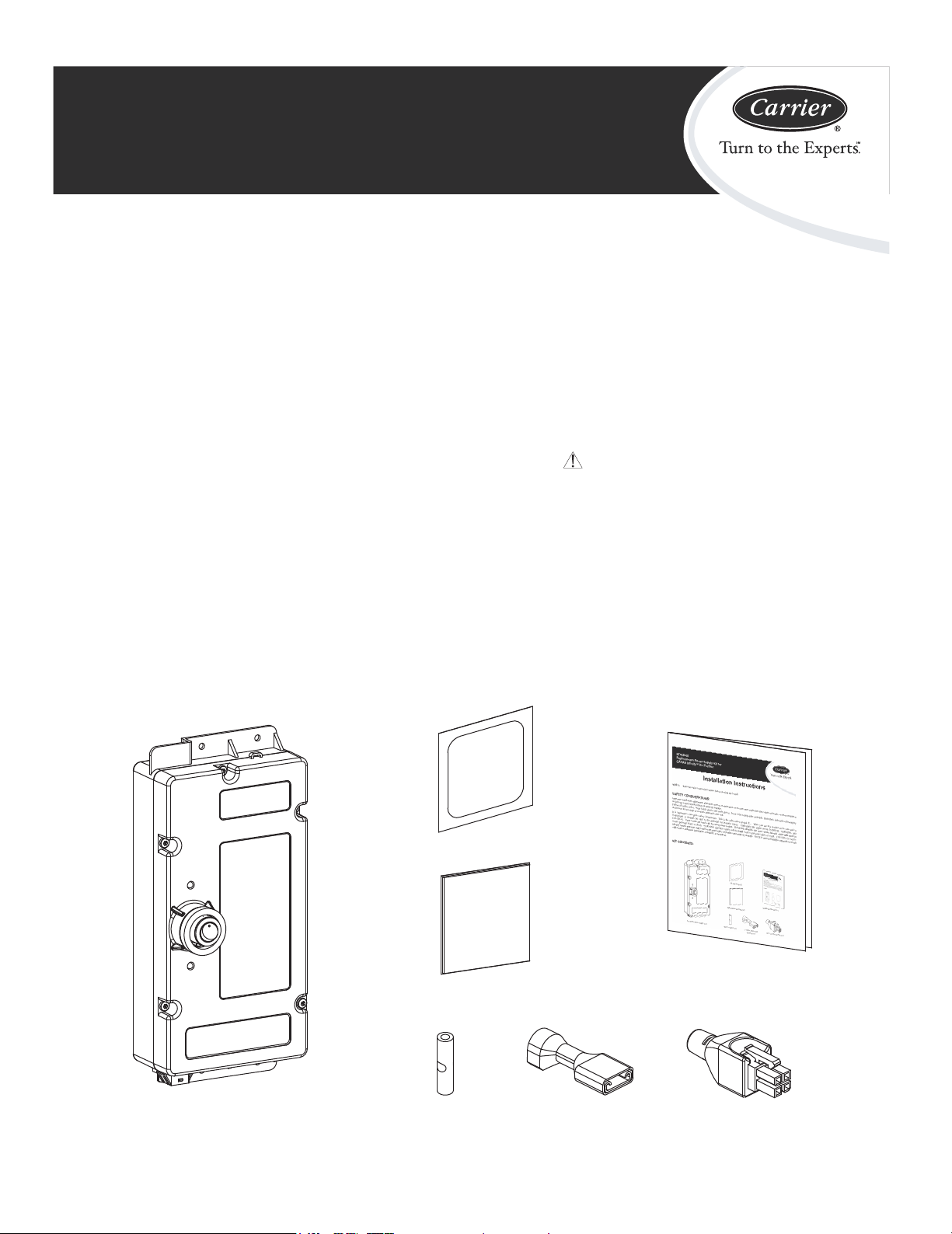
KIT CONTENTS:
Alcohol Swab (x1)
Installation Manual (x1)
Splice Insulation Tape (x2)
Power Supply Module (x1)
Butt Connector (x1) ¼” Quick Disconnect
Terminal (x1)
Air Flow Bypass Plug (x1)
Page 2
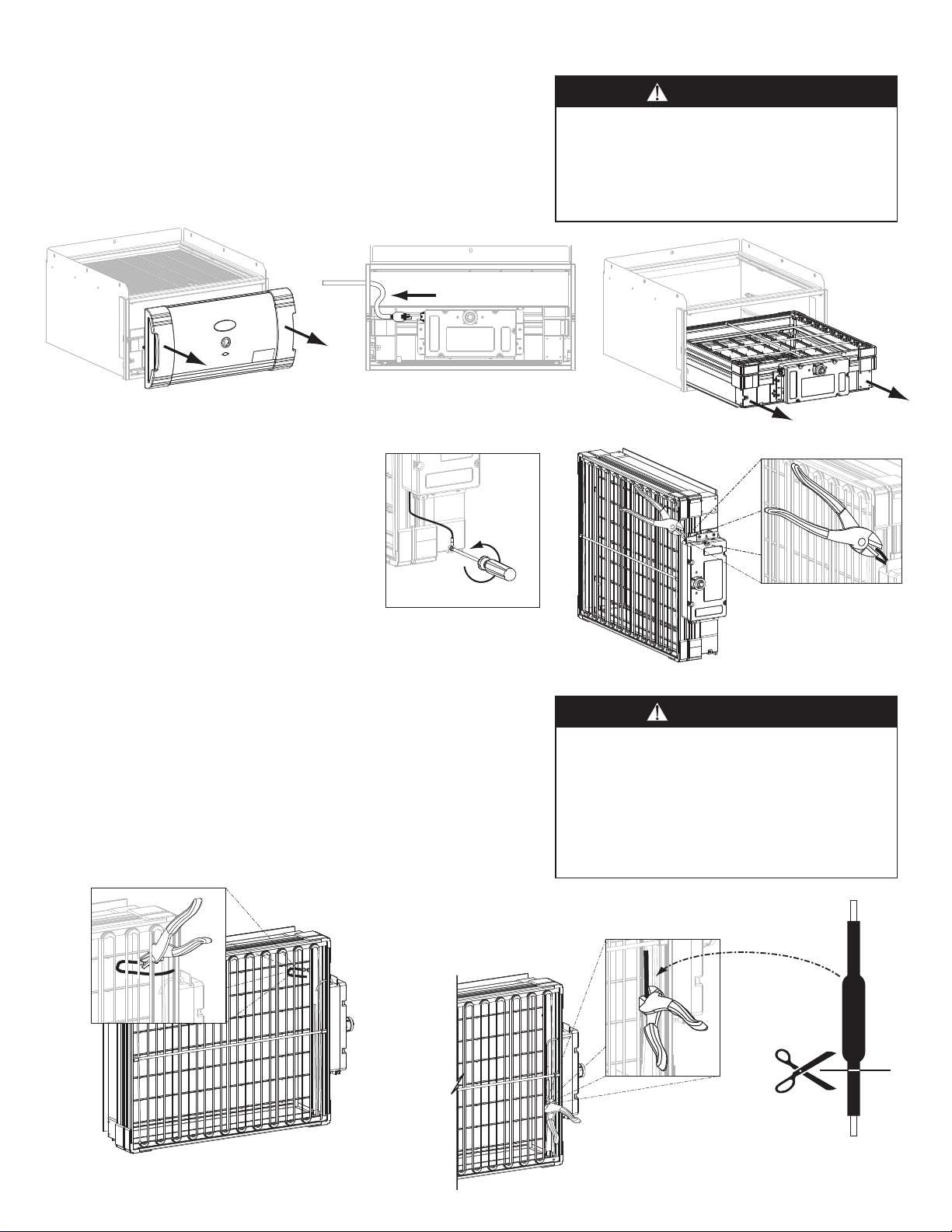
REMOVING THE OLD POWER SUPPLY:
1: Turn off power to the heating and cooling system and to the InfinityTM air
purifier.
2: Remove the air purifier door (Fig. 1). Disconnect the power cord and air
flow sensor cables from the power supply module (Fig. 2).
3: Remove the filter and enhancement module from the air purifier cabinet
(Fig. 3) and place on a flat surface in a well lit area.
Fig. 2
Fig. 1
4: Disconnect the green ground wire from the
enhancement module (Fig. 4).
5: Cut the two high voltage wires where they
exit the power supply enclosure (Fig. 5).
CAUTION
CUT HAZARD
Failure to follow this caution may result in personal
injury. Sheet metal parts may have sharp edges or
burrs. Use care and wear appropriate protective
clothing and gloves when handling parts.
Fig. 3
Fig. 4
6: Disconnect the ¼” quick disconnect terminal (with the cut wire)
from the ionization array and discard (Fig. 6) - this may require
the use of needle-nose pliers.
7: Cut the splice away from the media enhancement grid wire (Fig. 7).
Cut the media enhancement grid wire next to the wire splice under
the heat shrink tubing (Fig. 8).
Fig. 5
WARNING
ELECTRICAL SHOCK & HIGH VOLTAGE
HAZARD
Failure to follow this warning could result in
personal injury or death.
Before installing or servicing system, always turn
off main power to system. There may be more
than one (1) disconnect switch.
TO POWER SUPPLY
Fig. 6
Fig. 7
TO ENHANCEMENT GRID
Fig. 8
Page 3

8: Remove the power supply module from the enhancement
2 Screws
2 Screws
module by unscrewing the four Phillips head screws (Fig. 9).
You are now ready to install the new power supply.
INSTALLING THE NEW POWER SUPPLY:
1: Strip the red and black replacement power supply
wires ¼” from ends.
2: Insert the high voltage wires through the holes in the
enhancement face (Fig. 10-A). Make sure the wires
do not kink or have twists in them.
3: Mount the new power supply module to the
enhancement module using the four screws removed
earlier (Fig. 10-B).
NOTE: Make sure the green ground wire runs down
the groove in the enhancement module face behind
the power supply enclosure.
4: Reconnect the green ground wire to the enhancement
module (Fig. 11).
5: Crimp the new ¼” quick disconnect terminal onto the
red replacement power supply wire and connect to the
ionization array (Fig. 12). This may require the use
of needle-nose pliers.
Fig. 9
Fig. 10-B
CAUTION
UNIT OPERATION HAZARD
Failure to follow this caution may result in equipment
damage or improper operation.
Improper wiring will reduce unit performance.
Fig. 10-A
Fig. 11
Fig. 12
Page 4

6: Crimp the butt connector to the severed media cartridge enhancement grid wire (Fig. 13). Please note that the grid wires will
typically be black.
7: Crimp the opposite side of the butt connector to the black replacement power supply wire (Fig. 14).
CAUTION
UNIT OPERATION HAZARD
Failure to follow this caution may result in
equipment damage or improper operation.
Make sure the high voltage wire is routed
behind the horizontal fiberglass rod.
Fig. 13 Fig. 14
CAUTION
UNIT OPERATION HAZARD
Failure to follow this caution may result in equipment damage or
improper operation.
At this point it is critical that your hands are clean before applying the
splice insulation tape around the butt connector. Dirt and/or oil can
contaminate the insulation and cause the splice to fail.
8: Clean the butt connector and at least two (2) inches of the wires on
either side with the alcohol swab (Fig. 15).
9: Remove the backing paper from the splice insulation tape and center
on the butt connector along the length of the tape. Tightly wrap the
insulation tape around the butt connector and wires (Fig. 16).
10: Tuck the completed splice behind the media cartridge enhancement
grid (Fig. 17).
11: Insert the enhancement module back into the air purifier cabinet and
reconnect the power and air flow sensor cables.
12: Replace the door, turn the InfinityTM air purifier power switch to the
on position, and turn on the power to the heating and cooling system.
Fig. 15
Fig. 16 Fig. 17
Copyright Carrier Corp. • 7310 W. Morris St. • Indianapolis, IN 46231 Printed in China Edition Date: 2/07 Catalog No. IIK63000-C01
Manufacturer reserves the right to discontinue, or change at any time, specifications or designs without notice and without incurring obligations. Replaces: New
 Loading...