

Page 1
Number One
AirConditbning
l\Mer
Division of
Carrier Corporation
Carrier Parkway • Syracus
N Y 13221
Weathermaster III Dual-Compressor
Heat Pump
(Outdoor Coil Section; Indoor Compressor Section)
INDEX
Page
SAFETY CONSIDERATIONS
.............................
INSTALLATION.....................................................3
Step 1 — Check Equipment and Jobsite . 3
• UNPACKAGE UNITS
• INSPECT EQUIPMENT
• COMPLETE OR CONSIDER SYSTEM
REQUIREMENTS
Step 2 — Install Outdoor Coil
Section.................................................4
• ON THE GROUND
• ON THE ROOF
Step 3 — Install Indoor Compressor
Section.................................................5
Step 4 — Install Indoor Fan-Coil and
Electric Heater
Step 5 — Make Piping Connections
....................................
................
• REPLACE THE ACCURATER™
REFRIGERANT CONTROL PISTON(S)
• CONNECT REFRIGERANT LINES
Step 6 — Install Fan Control Package ... 6
Page
I
Step 7 — Install Outdoor Ambient
Switch...................................................6
Step 8 — Install Room Thermostat,
Outdoor Thermostat(s) and
Emergency Heat Relay
Step 9 — Make Electrical Connections... 8
.......................
8
• INSTALL A BRANCH CIRCUIT
DISCONNECT PER N.E.C.
• ROUTE LINE POWER LEADS INTO
COMPRESSOR SECTION
• CONNECT GROUND LEADS AND
POWER WIRES
• CONNECT POWER LEADS FROM
INDOOR COMPRESSOR SECTION
TO OUTDOOR COIL SECTION
5
5
• CONNECTCONTROL WIRING
INITIAL START-UP................................................9
SEQUENCE OF OPERATION.............................. 9
SERVICE.................................................................. II
MAINTENANCE .................................................... 15
SAFETY CONSIDERATIONS
Installation and servicing of air conditioning
equipment can be hazardous due to system pressure
and electrical components. Only trained and quali
fied service personnel should install, repair or
service air conditioning equipment.
Untrained personnel can perform basic mainten
ance functions of cleaning coils and filters and re
placing filters. All other operations should be per
formed by trained service personnel. When working
on air conditioning equipment, observe precautions
in the literature, tags and labels attached to the unit
© Carrier Corporation 1979
and other safety precautions that may apply.
Follow all safety codes. Wear safety glasses and
work gloves. Use quenching cloth for brazing opera
tions. Have fire extinguisher available for all brazing
operations.
Form 38HQ-6SI
Page 2
4 -0" OVERHEAD SPACE REQUIRED
FOR SERVICE AND AIRFLOW
VAPOR LINE CONN (ON SERVICE VALVE)
i-b*'-
liquid line
CONN. (ON
SERVICE VALVE)
5" ll“
15’ Is
MTG SLOTS
(USE ANY 2)
^ SPACE REQUIRED FOR SERVICE ^AIRFLOW
Certified dimension drawings available on request
38 HQ
OUTDOOR
COIL
SECTION
i DIAM HOLE
FOR CONTROL
WIRING
DRAINAGE HOLES
I i' DIAM
HOLE FOR
POWER
WIRING
k DIAM HOLE
VAPOR LINE CONN TO
OUTDOOR COIL
VAPOR LINE CONN.
TO INDOOR COIL ‘
38HQ
INDOOR
COMPRESSOR
SECTION
SPACE REQUIRED FOR SERVICE
FOR COMPRESSOR
SECTION LINE POWER
WIRING
Certified dimension drawings available on request
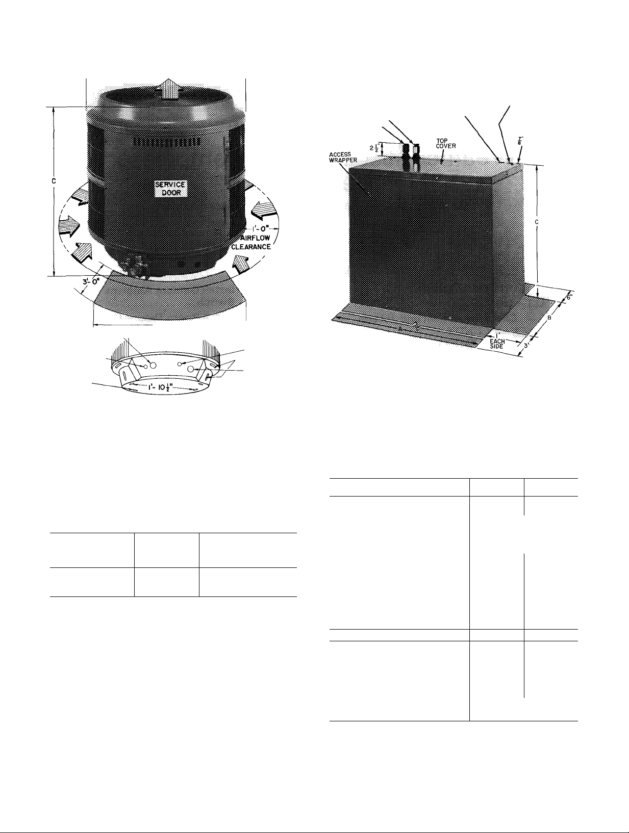
Fig. 2 — Dimensions and Connections, 38HQ
Indoor Compressor Section (Table 2)
DIAM HOLE
FOR OUTDOOR
COIL SECTION
LINE POWER WIRING
(SEE ELECTRICAL
DATA AND WIRING)
DIAM HOLE FOR
CONTROL WIRING
Fig. 1 — Dimensions and Connections, 38HQ
Outdoor Coil Section (Table 2)
Table 1 — Carrier-Approved 38HQ
Weathermaster III Dual-Compressor
Heat Pump Systems
INDOOR
COMPRESSOR
SECTION
38HQ227
38HQ234
OUTDOOR
COIL
SECTION
38HQ940
38HQ960
INDOOR
FAN/COIL
40FS160/28VQ036
40FS200/28VQ042
Table 2 — Physical Data
INDOOR COMPR SECTION
Operating Wt (lbs)
38HQ227
205
Dimensions (ft-in.)
Width
A
Depth B
Height
C
1-11-1/8 (add 3/4-in for
Refrigerant Fittings
Compressor
no. 1
MD2713GM
(46)
(Oil Recharge, oz) no. 2
MD3413GM
(46)
AccuRater Size (in.)
Indoor no 6 ( 0670) no 7(0760)
Outdoor no 3 (.0550)*
Refrig Conn (in.)
OUTDOOR COIL SECTION
Operating Wt (lb)
3/4 3/4
38HQ940 38HQ960
107
Dimensions (ft-in.)
Diameter
Unit Height B
Coil Height
A
C
2-5-1/4
2- 8 3- 8
1-11 2-11
Refrig Conn
Vapor (in., ODF)
Liquid (in., ODF)
3/4, Compatible Fitting
3/8, Flare Fitting
*Piston size shown is shipped with section Remove factory-
installed piston: replace with size shown per text
38HQ234
2-2-3/32
1-4-3/16
MD3413GM
MD3413GM
no 5 ( 0635)
2-5-1/4
225
(46)
(46)
125
©
Page 3
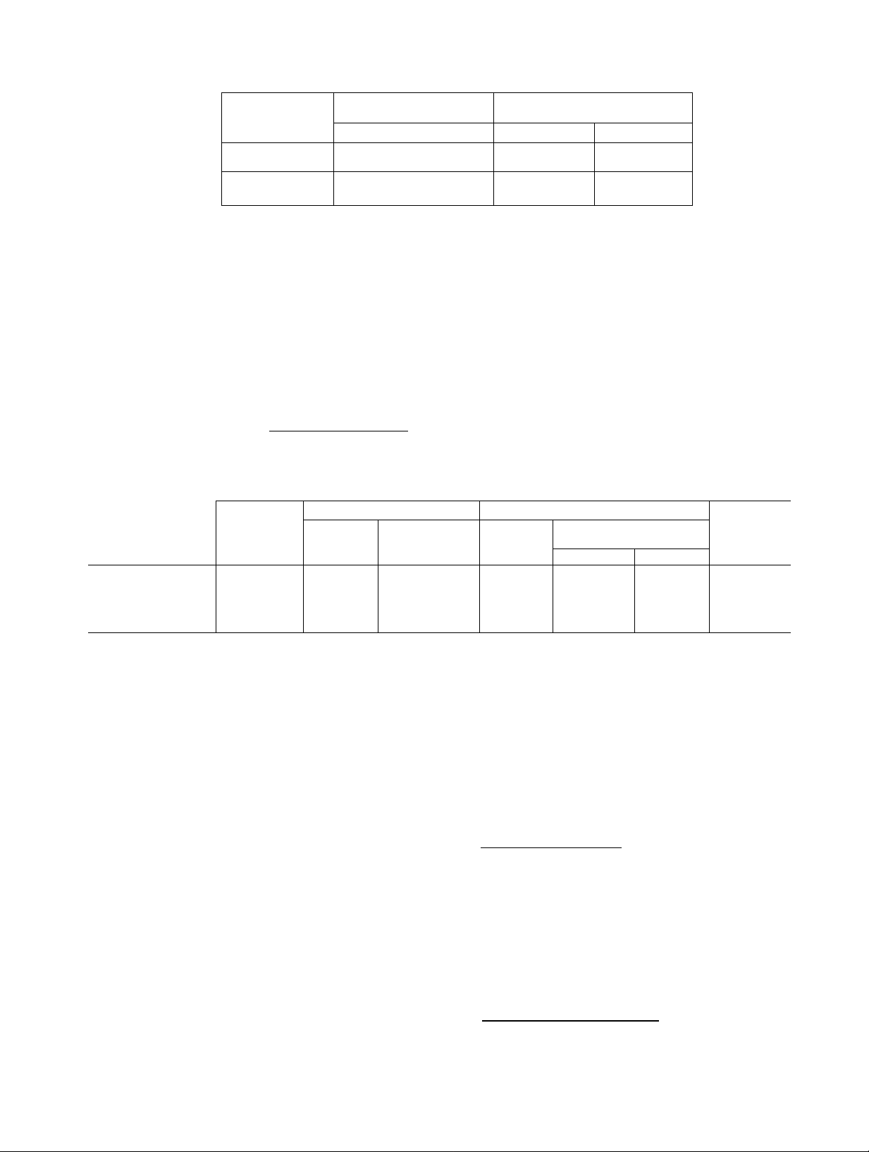
Table 3 — Heater Airflow Data
COMPRESSOR
PART NO.
38CQ900102
38CQ900122
38CQ900132
38CQ900152
38CQ900172
38HQ900011
38HQ900002
38RQ900012
38CQ900072
38RQ900072
TUBING
PACKAGE
38GC900071 10
38GC900081 18
38GC900091
38GC900101 35
38GC900111 50
_ ___ TUBING
INDOOR
SECTION
38HQ227
38HQ234
HEATER MINIMUM ALLOWABLE
SIZE
8 thru 20 kw
(40FQ91 6010 thru 090)
10 thru 25 kw
(40FQ920060 thru 1 50)
Airflow (cfm)
1150
1550
Fan Speed
Low
Low
Table 4 — Accessories
DESCRIPTION
Six 38CQ900081 Low-voltage Honeywell Thermostat (HH07AT071) and Thermostat Subbase (HH93AZ073)
with automatic changeover
Six 38CQ900111 Low-voltage Honeywell Thermostat (HH07AT071) and Thermostat Subbase (HH93AZ075)
with manual changeover
Six 38CQ900091 Liquid Line Filter-Drier
Six 38CQ900141 Solid State Time Guard (24 v)
SixHH22AG110 Optimizer Control
Hot Shot Heat Reclaim Device
Six 38HQ900001 Outdoor Thermostat
Six 38RQ900001 Emergency Heat Relay
Six 38C0900061 two-packs. Flare (3/8-in ) to compatible (3/8-in ) couplings
Six 38RQ900061 Heat Pump Stand for Outdoor Coil Section
Suction*
Tube End
Evap
3/4
3/4
O D. (in )
Cond
3/4
3/4
3/4
3/4
COMPR
SECTION
38HQ227
38HQ234
Length
(ft)
25
Liquid
O.D
(in.)
3/8
3/8
3/8
3/8
3/8 3/8
1-1/8 in OD Suction Tube, Field Supplied
Tube End
OD (in )
3/8
3/8
3/8
3/8
0 D.
(in.)
3/4 3/4 3/4
3/4 3/4
3/4 3/4
3/4
3/4
‘Suction line is insulated and has a 90° bend at one end
INSTALLATION
Step 1 — Check Equipment and Jobsite
UNPACKAGE UNITS — Move units to final loca
tion. Slide units from cartons taking special care
not to damage service valves, compatible fittings
or grilles. Check unit model numbers. Use only
Carrier-approved unit combinations in system. See
Table 1.
INSPECT EQUIPMENT — File claim with ship
ping company if shipment is damaged or incomplete.
COMPLETE OR CONSIDER SYSTEM RE
QUIREMENTS before installing the 38HQ units.
Consult local building codes and National Elec
trical Code (NEC) for special installation
requirements.
When installing units, allow sufficient space for
airflow clearance (outdoor unit), wiring, refrigerant
piping and servicing unit. Position outdoor unit so
water or ice from roof cannot drop directly on top
of unit. Maximum allowable vertical distance be
tween indoor and outdoor sections is 50 feet. It is
strongly recommended that 38HQ units be used
with only Carrier-approved indoor sections (see
Table 1).
Outdoor Coil Section — Make provision for con
densate drainage and defrost water disposal whether
unit is installed on ground, roof or off-the-wall
platform. Outdoor unit must be elevated 12 in. to
18 in. in areas of heavy snowfall. (Ensure unit base-
pan drainage holes are not blocked. See Fig. 1.) See
Step 2, Install Outdoor Coil Section for details.
Roof installation method for 38HQ depends on
building construction and special requirements of
local codes. Make sure roof can support unit weight.
Indoor Compressor Section — Locate unit in base
ment, garage or utility room. Indoor locations with
in the living space are not recommended. Basement
installations also require careful planning to avoid
areas directly under bedrooms, living rooms, etc.
Page 4
Insert felt isolation pad (factory supplied) be
tween unit and a level rigid mounting base to absorb
vibration. Isolate interconnecting tubing from
framing and ductwork or where tubing runs thru
stud spaces, enclosed ceilings or pipe chases. Use
isolation type hanger, Fig. 3, since rigid fastening
will transmit pulsation to structure creating ob
jectionable sound.
. -.-.A ■ ■
System Refrigerant Control consists of factoryinstalled bypass-type AccuRater™ devices located
as shown in Fig. 15. These metering devices include a
replaceable orifice piston that is calibrated to
regulate refrigerant flow. Piston data is given in
Table 2. In some instances, the factory-installed
piston must be replaced by a factory-supplied re
placement piston. Where required, substitute
pistons as described in Step 5 and as indicated on
tags attached to system AccuRater devices.
Step 2 — Install Outdoor Coil Section
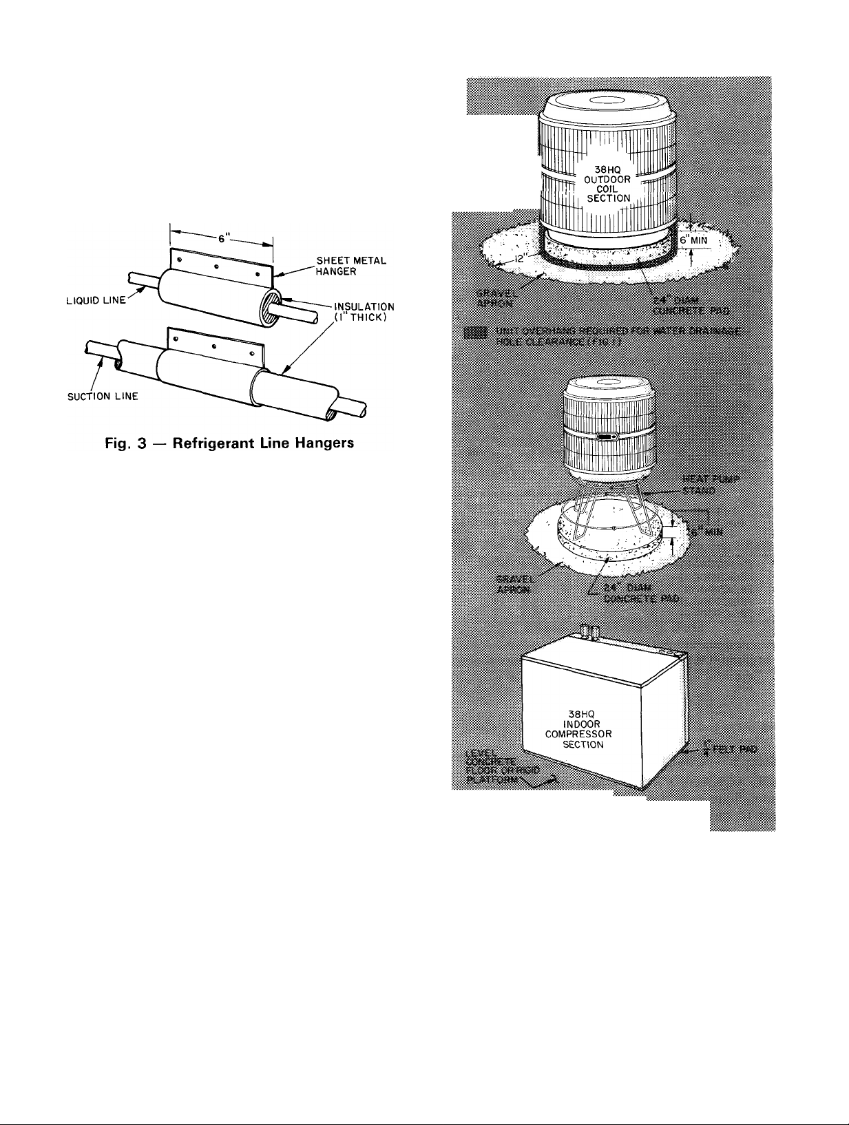
ON THE GROUND — Use a solid, level concrete
pad as shown in Fig. 4. Position unit so that coil
drainage holes in basepan overhang the pad. (See
Fig. 1 for drainage hole locations.) Be sure pad does
not obstruct drainage holes (water drains from holes
during heating and defrost cycles). Attach unit to
pad with 1 / 4-in. mounting bolts. Any 2 holes in unit
basepan may be used to fasten unit to pad.
Construct round, 24-in. diameter 6-in. thick pad a
minimum of 6 in. above grade to provide clearance
under holes for drainage and ice build-up. In areas
where prolonged subfreezing temperatures or snows
occur: increase clearance by using accessory heat
pump stand to support unit 12 to 18 in. off concrete
base. See Fig. 4. Be sure stand does not obstruct coil
drainage holes. Avoid mounting unit in prevailing
winds to minimize effect on defrost performance.
Construct wind break if necessary. Extend a 12-in.
gravel apron around pad for condensate and defrost
water drainage field.
Provide support bracket from structure or other
solid support to outdoor unit to give stability. Since
it is lightweight, the outdoor section may be
Fig. 4 — Unit Support Details
mounted on a platform attached to or built out from
structure. Construct platform using drainage and
clearance recommendations above. Locate and con
struct platform to avoid possible transfer of unit
vibration to structure. See Table 2 for unit weight.
ON THE ROOF: Install a level platform or frame to
support unit. Elevate unit for proper clearance as
previously described for on-the-ground installation.
Plan roof design and water drainage to prevent unit
from sitting in water. Flash all roof openings to
prevent leaks.
Page 5
Step 3 — Install Indoor Compressor Section on
a level, rigid, solid platform or concrete floor. Do
not install in a living area.
Insert 1/4-in. asphalt-impregnated felt pad
(supplied) between unit basepan and mounting
surface to provide full unit support and vibration
attenuation. (Do not use vibration isolators under
corners of basepan.)
Step 4 — Install Indoor Fan-Coil and Electric
Heater as described in Installation Instructions
supplied with this equipment. Install and connect
thermostats and other controls as described in the
steps that follow.
Step 5 — Make Piping Connections — The
38HQ sections may be connected to indoor fan-coil
using Carrier accessory tubing packages or fieldsupplied tubing of refrigerant grade. See Table 2 for
unit piping connection types, sizes and line size
recommendations and Table 4 for accessory tubing
sizes. Maximum allowable system liquid line length
is 100 feet. Maximum vapor line length from com
pressor section to indoor coil is 50 feet. Maximum
vapor line length from compressor section to out
door coil is 50 feet.
When other than 25 ft of interconnecting piping
is used, follow special requirements described in
Refrigerant Charging. Do not use less than 10 ft of
vapor or liquid line.
Do not use damaged or contaminated tubing.
Always evacuate or purge indoor coil, compressor
section and tubing system. When purging, use fieldsupplied refrigerant, not unit refrigerant.
When making tubing connections, be sure to
provide clearance at unit for electrical connections.
Follow tubing isolation recommendations described
previously.
REPLACE THE ACCURATER™ REFRIG
ERANT CONTROL PISTON(S) before connect
ing refrigerant lines as applicable. Refer to tags
attached to AccuRater device. Replacement pistons
are shipped with compressor section and are to be
installed as directed on tag. Replacement procedure,
briefly described below, is detailed on tag. Also, see
AccuRater Servicing for additional information.
When connecting indoor compressor section
38HQ227 to outdoor coil section 38HQ940, remove
no. 4 piston from outdoor coil AccuRater device;
replace with no. 3 piston. Attach AccuRater identi
fication sticker to unit (replacing existing sticker, if
any).
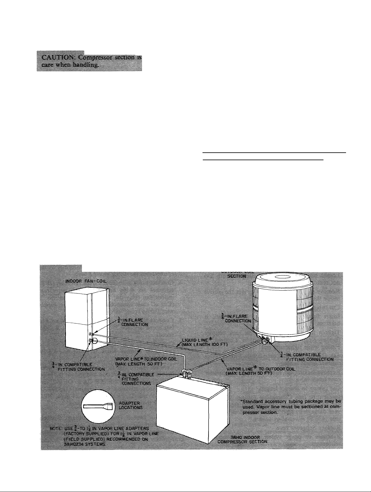
CONNECT REFRIGERANT LINES to fittings on
indoor and outdoor sections. Fig. 1, 2 and 5. Indoor
compressor section has 2 Compatible Fitting vapor
line connections. Outdoor and indoor fan-coil
sections have Compatible Fitting vapor line connec
tion and liquid line flare connection.
Flare and connect liquid line from outdoor coil
section to indoor fan-coil unit. It is not necessary
to flare system liquid line if an accessory flare-to-
Fig. 5 — Refrigerant Piping Connections
5
Page 6
Compatible Fitting coupler is used for liquid line
connection. See accessory coupler, Fig. 6.
Connect vapor line from outdoor coil section to
indoor compressor section, and from compressor
section to indoor fan-coil. Section vapor line as
required (Fig. 5). Use correct compressor section
vapor line connection to indoor and outdoor coils.
Unit Compatible Fittings permit mechanical or
sweat connection as described below.
When a 1-1/8 in. field-supplied vapor line is used
on 38HQ234, four field-supplied 3/4-in. to 1-1 / 8 in.
vapor line adapters must be provided.
Insulate Refrigerant Lines — After making tubing
connections, the compressor section fittings must be
insulated. Butt the Armaflex tubing insulation (pro
vided in tubing package) against the Compatible
Fittings. Secure the insulation with Prestito or an
equivalent material which provides both adhesion
and insulation. Also wrap the Compatible Fittings
with Prestito to prevent sweating.
Mechanical Connection-to-Compatible Fitting
(Mate one set of connections at a time.)
1. Loosen nut on Compatible Fitting one turn. Do
not remove.
2. Remove plug and be sure 0-ring is in the groove
inside the Compatible Fitting.
3. Cut tubing to correct length.
4. Insert tube into Compatible Fitting until it
bottoms.
5. Tighten nut until it bottoms on back coupler
flange. Keep tube bottomed in Compatible
Fitting while tightening nut.
Sweat Connection-to-Compatible Fitting (Use
refrigerant grade tubing.)
1. Remove locking nut, rubber O-ring and Schrader
core from valve.
2. Cut tubing to correct length.
3. Insert tube into Compatible Fitting. Wrap top
and bottom of service valves in wet cloth to pre
vent damage by heat. Solder with low tempera
ture (430 F) silver alloy solder.
4. Replace Schrader core.
5. Evaeuate or purge system with field-supplied
refrigerant.
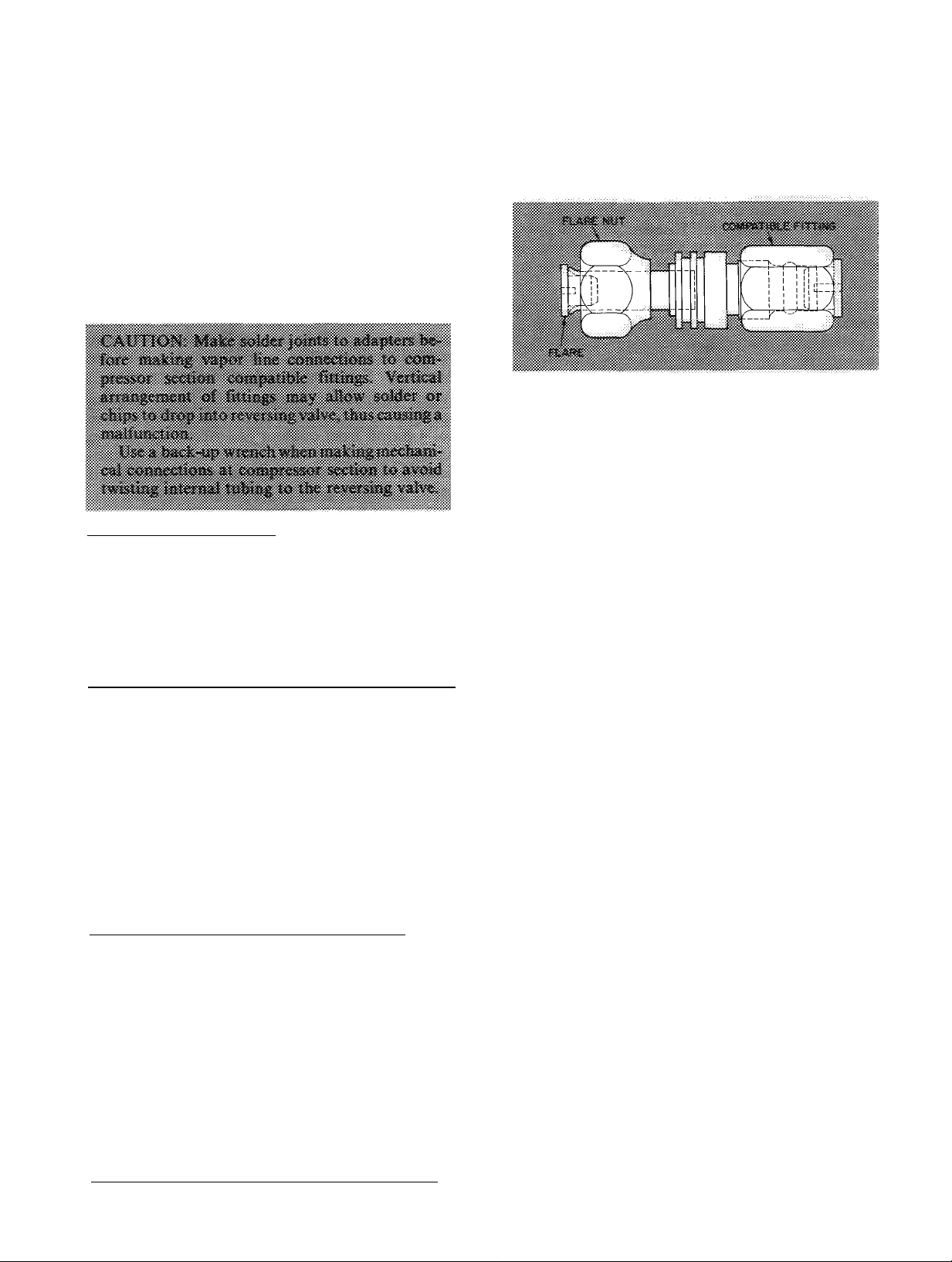
Accessory Flare-to-Compatible Fitting Coupler is
shown in Fig. 6. Attach flare nut on coupler to flare
fitting on unit liquid line connection. Connect liquid
line to Compatible Fitting using mechanical or
sweat connection. When mechanical connection is
made, use 2 wrenches to tighten Compatible Fitting
nut — one to hold coupler and one to tighten nut.
Fig. 6 — Accessory Coupler
Step 6 — Install Fan Control Package (factory
supplied; packaged separately inside indoor com
pressor section) — This control, consisting of a
transformer and a relay, provides high-speed fan
operation when both compressors are energized.
Refer to connection diagram in Fig. 7 for wiring
details. Install control as follows:
1. Remove factory-installed transformer from
indoor fan-coil unit electric heater package.
Refer to 40FS service instructions as required.
2. Install fan control package in upper right-hand
corner of the 40FS.
3. Route wires from controls to heater package thru
knockouts provided. Restore transformer wiring
connections including ground wire.
4. Connect black wire from indoor fan relay (IFR)
terminal no. 4 (or no. 6) to black wire from
indoor fan relay no. 2 (IFR-2) terminal no. 3.
(Cut off male connector from IFR wire; supply
wire nut to splice wires.)
5. Connect black wire from IFR-2 terminal no. 6 to
fan speed selector block terminal no. 1 (high
speed).
6. Connect blue wire from IFR-2 terminal no. 1 to
fan speed selector block terminal no. 3 (low
speed).
7. Connect low-voltage field control wires between
indoor compressor section and indoor fan relay
(IFR-2) orange pigtails (TB OA to OFR-2, ter
minal no. 4; contactor C-2, terminal C to IFR-2,
terminal no. 5). Field-supplied, 24-gage, NEC
Class 2 thermostat wire may be used.
Step 7 — Install Outdoor Ambient Switch
(OA) (factory-supplied; packaged separately inside
indoor compressor section) — This switch activates
compressor no. 2 when the first heating thermal
balance point is reached. The switch is installed in
the same manner as the outdoor thermostat (step 8),
except refer to Fig. 7 for correct wiring.
Page 7

LEGEND
C-2
IFR
PL
SEQ
TB
Tran
NOTES;
1
2
Contactor
Indoor Fan Relay
Plug, Fan
Sequencer
Terminal Board
Transformer
Junction
Component Connection (Marked)
o
Field Splice
Field Power Wiring
Field Ground Wiring
Field Control Wiring
Use copper conductors only.
May be terminal board or fuse block depending
on heater model used
Will be terminal no 4 on 40FQ916 models,
and terminal no 6 on 40FQ920 models
FAN CONTROL PACKAGE
THERMOSTAT 40FQ
SUBBASE ELECTRIC HEATER
HH93AZ0730R TERMINAL
HH93AZ075 BOARD
THERMOSTAT
SUBBASE
HH93AZ073 OR
HH93AZ075
40FQ
ELECTRIC HEATER
TERMINAL
BOARD
COOLING AND TWO-STAGE HEATING
(38H0 WITH 40FS/28H0.V0
EOUIPPED WITH ELECTRIC HEATER;
EMERGENCY HEAT, NO OUTDOOR THERMOSTATS)
DFT — Defrost Thermostat
EHR — Emergency Fleet Relay
OA — Outdoor Ambient Switch
ODT — Outdoor Thermostat
_______ Factory Wiring
_______
Field Wiring
38HQ
COMPRESSOR
SECTION
TERMINAL BOARD
38H0
COMPRESSOR
SECTION
TERMINAL BOARD
THERMOSTAT
SUBBASE
HH93AZ073 OR
HH93AZ075
THERMOSTAT 40FQ 38HQ
SUBBASE ELECTRIC HEATER COMPRESSOR
HH93AZ0730R TERMINAL SECTION
HH93AZ075 BOARD TERMINAL BOARD
(38HQWITH 40FS/28HQ/VQ
EQUIPPED WITH ELECTRIC HEATER;
EMERGENCY HEAT, TWO OUTDOOR THERMOSTATS)
40 FQ
ELECTRIC HEATER
TERMINAL
BOARD
EOUIPPEDWITH ELECTRIC HEATER;
EMERGENCY HEAT, ONE OUTDOOR THERMOSTAT)
38H0
COMPRESSOR
SECTION
TERMINAL BOARD
"Transformer (75 va) located in fan control package
fTerminal L is identified as terminal X on some former thermostats (Required for system
malfunction warning indicator on compressor section )
fRemove 1 or both factory-installed jumpers (connection B) when installing outdoor ther
mostats (ODT) shown in connections C and D
Fig. 7 — Control Circuit Connections
Page 8

Attach one lead to compressor terminal board
connection OA. Connect other lead to line side of
defrost thermostat.
Set switch at temperature of first thermal balance
point (heating). This balance point is provided by
CLIC load estimating program. Further adjust
ments can be made following operating experience.
Step 8 — Install Room Thermostat, Outdoor
Thermostat(s) and Emergency Heat Relay —
Follow Installation Instructions shipped with these
accessories plus the instructions in the sections that
follow. Connect as described in step 9.
INDOOR THERMOSTAT — Use only Carrier
indoor thermostat and subbase as shown in Table 4.
Set heat anticipator settings according to Table 5.
These settings may be changed slightly to provide
a greater degree of comfort for certain installations.
section of outdoor coil section junction box. Fasten
in place with sheet metal screws.
EMERGENCY HEAT RELAY — This accessory is
required when 2 or more outdoor thermostats are
used. It is automatically energized by the manuallyoperated emergency heat switch in the indoor ther
mostat subbase. The indoor thermostat locks out
the compressor and the relay bypasses the outdoor
thermostats for electric heater operation during heat
pump shutdown. When one outdoor thermostat is
used, an emergency heat relay is not required. The
emergency heat switch in the indoor thermostat
subbase bypasses the outdoor thermostat, locks out
the compressor and activates the electric heater.
Install emergency heat relay in a convenient loca
tion on indoor unit. Attach with sheet metal screw.
Connect relay as shown in Fig. 7.
Table 5 — Thermostat Heat Anticipator
Settings
INDOOR
COMPR
SECTION
38HQ227 38HQ940
38HQ234 38HQ960
OUTDOOR
COIL
SECTION
INDOOR
UNIT WITH
ELECTRIC
HTR
40FS160 with
40FQ916010
thru 090
40FS200 with
40FQ920060
thru 150
HTR
KW
8 thru
20
10 thru
25
ANTICIPATOR
SETTINGS
Second
First
Stage
Fixed 16
Fixed 49
Stage
OUTDOOR THERMOSTAT ACCESSORY pro
vides adjustable outdoor control of accessory
electric heater (used on indoor fan-coil). This ther
mostat closes on a drop in outdoor temperature.
It energizes a stage of electric heat when the out
door temperature setting is reached, provided the
room thermostat is on the second stage of heating.
One outdoor thermostat is recommended for each
stage of electric heat after the first stage. Connect
as described in Step 9. Set the outdoor thermostats
progressively lower for each stage. Refer to heat
load of building and unit capacity to determine the
correct outdoor thermostat settings. Locate maxi
mum of 2 outdoor thermostats in control voltage
Step 9 — Make Electrical Connections — In
stall field wiring in accordance with local and
national fire, safety and electrical codes. Be sure
voltage to units is within ± 10% of voltage indi
cated on nameplate. Contact local power company
for correction of improper line voltage.
When making electrical connections, provide
clearance at unit for refrigerant piping connections.
See Table 6 for recommended wire and fuse sizes.
Line power connections and control circuit connec
tions are shown in Fig. 7 and 8.
Route line and control power wiring for 38HQ
outdoor coil from connections in the 38HQ in
door compressor section. Use 14-ga (minimum) line
power wire size to outdoor coil section when total
wire length connecting compressor section to coil is
under 25 feet. If over 25 ft, use same wire size as
compressor section branch circuit.
Table 6 — Electrical Data
VOLTAGE
INDOOR
COMPR
SECTION
38HQ227 38HQ940 230
38HQ234 38HQ960
FLA — Full Load Amps
ICS — Indoor Compressor Section
LRA — Locked Rotor Amps
OCS — Outdoor Coil Section
OFM — Outdoor Fan Motor
RLA — Rated Load Amps
‘Permissible limits of the voltage range (for limited period of time)
at which the units will operate satisfactorily
fOutdoor coil section wiring — for 25 ft wire run or less, use
OUTDOOR
COIL
SECTION
Nom
1-Ph
60-Hz
230
Operating*
Max Min LRA
254
254 207
COMPR
1
RLA LRA
207 72 17 88
20
88
COMPR
2
94
BRANCH CIRCUIT
OFM
(FLA)
RLA
1 5 6
17 8
2 3 4
21 2
minimum 14 AWG size wire For longer wire run use same size
as supply to compressor section
^Required when using nonmetallic conduit
“Maximum dual element fuse size
NOTES;
1 All units have 24-v control circuit which requires external
power source
2 Copper wire size table based on 60 C Use copper or copper-clad
aluminum wire to indoor section; copper wire only to outdoor
section Use latest National Electrical Code for wire sizing
Min Size
(AWG)
ICS
Power Wire
OCS
ICS
55
14t
75
14t
Max Ft
OCS
25t
25t
Gnd Wire
Sizet
(AWG)
OCS
ICS
10 14t
10 14t
Min
Ckt
Amps
40 8 50
48 8
Max
Fuse
Amps“
60
Page 9

FACTORY WIRING
Fig. 8 — Line Power Connections
INSTALL A BRANCH CIRCUIT DISCONNECT
PER N.E.C. of adequate size to handle compressor
section starting current. Provide a separate dis
connect switch for outdoor coil section. Provide a
separate disconnect for indoor fan-coil and for each
accessory electric heater circuit as required. (See In
door Unit and Electric Heater Installation, Start-Up
and Service Instructions.) Locate disconnect(s)
within sight of and readily accessible to the units, per
section 440-14 of National Electrical Code (NEC).
ROUTE LINE POWER LEADS INTO COM
PRESSOR SECTION — Extend lead from discon
nect per N.E.C. thru 1-1/8 in. hole provided in com
pressor section top panel (Fig. 2) and into control
box. Extend line power leads for outdoor coil
section thru 7/8-in. hole provided in compressor
section top panel and into control box.
CONNECT GROUND LEADS AND POWER
WIRES — Connect ground leads to the ground lug
in control box for safety. Splice compressor section
line power leads to yellow and black pigtails, and
outdoor coil section power leads to brown and blue
pigtails. Use wire nuts and tape at each splice con
nection as shown in Fig. 8.
CONNECT POWER LEADS FROM INDOOR
COMPRESSOR SECTION TO OUTDOOR
COIL SECTION thru secondary disconnect switch.
From this disconnect switch extend leads thru
hole provided in outdoor eoil section basepan
(Fig. 1) and into line voltage seetion of junction
box. Fig. 14. Splice leads to black and blue pigtails
with wire nuts.
CONNECT CONTROL WIRING (24-v) — Extend
wiring thru 7 / 8-in. grommeted hole in compressor
section top panel (Fig. 2), and to control wiring
terminal board on side of control box. Connect
leads to terminal board as shown in Fig. 7. Extend
and connect control wiring from compressor section
to outdoor coil section as required. Make splice
connections in low-voltage section of coil junction
box.
Use indoor fan-eoil transformer as 24-v supply for
system. Be sure fan eontrol package is installed as
described in Step 6. Package contains 75-va trans
former of adequate capacity to handle system
current.
INITIAL START-UP
The compressors in the indoor compressor
section are equipped with crankcase heaters. It is
reeommended that the heaters be energized a
minimum of 24 hours before starting the system. To
energize crankcase heaters only, set the thermostat
at OFF position and turn on main power to
compressor section.
To Start System — (Be sure crankcase heaters
have been energized for 24 hours.) Adjust the ther
mostat as follows;
1. Set selector switch at OFF.
2. Turn on main disconnect switch(es) to indoor
and outdoor units.
3. Set fan switch as desired (ON or AUTO.).
4. Set thermostat dial at desired temperature.
5. Set selector switch at HEAT or COOL.
Check system refrigerant charge. See Service —
Refrigerant Charging.
SEQUENCE OF OPERATION
Fan Switch at AUTO. Position, Thermostat at
ON Position (Crankcase heater is on as soon as the
field power supply is on.)
THERMOSTAT CALLS FOR COOLING
1. First-stage cooling thermostat (Co) closes and
the reversing valve solenoid (RVS) is energized.
The RVS actuates the reversing valve and
switches the system to cooling.
2. Second-stage cooling thermostat (Cl) closes. If
the low-pressure switch (LPS) is closed, com
pressor contactor (C) is energized and compres
Page 10

sor no. 1 starts. At the same time, the outdoor fan
motor (OFM) starts and the defrost timer (DT) is
energized although it is not functional in the
cooling mode; the indoor fan relay (IFR) is
energized and the indoor fan motor (IFM) starts.
Compressor no. 2 does not run in COOL mode.
When the second stage of cooling is satisfied, Cl
opens. The compressor stops; the indoor and out
door fans stop; DT is de-energized. When the con
trolled temperature drops approximately 1 F below
the cooling set point, Co opens. RVS is de-energized
and the reversing valve switches to heating (normal
position). The unit is shut down except for the two
compressor crankcase heaters, which remain on as
long as the field power supply is on.
THERMOSTAT CALLS FOR HEATING (The
reversing valve is de-energized, in heating position.)
1. First stage heating thermostat (HI) closes. Com
pressor contactor no. 1 (Cl) is energized and
compressor starts; outdoor fan motor (OFM)
starts; defrost timer (DT) is energized. Indoor
fan relay (IFR) is energized and indoor fan
motor (IFM) starts. When the outdoor ambient
switch (OA) closes (at first thermal balance
point), compressor contactor no. 2 (C2) is ener
gized and compressor no. 2 starts. Compressor
no. 1 and compressor no. 2 operate simul
taneously as long as OA is closed. The crankcase
heaters are de-energized when both compressors
are running.
2. Second-stage heating thermostat (H2) closes and
activates the first accessory heater element
sequencer thru indoor thermostat terminal W2.
The first-stage electric heater element is energized
immediately and the other heater elements are
energized at regular intervals thru the sequencers.
Separate outdoor thermostats may be used to
energize the second sequencer and bring on addi
tional heater elements if more incremental heat
control is desired.
When the second stage of heating is satisfied, H2
opens and the electric heater(s) shuts off. When the
first stage of heating is satisfied, HI opens and the
unit shuts down, except for the compressor crank
case heater, which remains on as long as the field
power supply is on.
Unit Controls and Safety Devices
HIGH-PRESSURE RELIEF VALVE is located in
compressor. Relief valve opens at a pressure
differential of approximately 500 psi between
suction (low side) and discharge (high side) to allow
pressure equalization.
INTERNAL CURRENT AND TEMPERATURE
SENSITIVE OVERLOAD resets automatically
when internal compressor motor temperature drops
to a safe level (overloads may require up to 45 min
utes to reset). When an internal overload is suspected
of being open, check by using an ohmmeter or con
tinuity tester. If necessary, refer to Carrier Standard
Service Techniques Manual, Chapter 2, Electrical,
for complete instructions.
LOW-PRESSURE SWITCH is located in compres
sor section on suction line between reversing valve
and accumulator. Provides loss-of-charge protec
tion by shutting compressor off if suction pressure
drops below setting. Low-pressure switch settings
are: open, 5 ± 3 psig; close, 20 ± 5 psig.
CRANKCASE HEATERS are activated by a relay.
Heaters derive power from contactor no. 2 and are
energized when compressors are off or when only
one compressor is functioning.
The heater keeps the crankcase warm during the
off cycle and thus prevents dilution of the oil with
the refrigerant, assures good lubrication, and pre
vents loss of oil from crankcase during start-up.
If the electrical disconnect switch to the compres
sor section has been off for an extended period of
time, the crankcase heater should be energizedfor 24
hours before starting the compressor.
SIGNAL-LOC™ SYSTEM MALFUNCTION
WARNING INDICATOR AND LOCKOUT —
Indoor compressor section is equipped with a solid-
state warning logic circuit that protects the system.
In case of a malfunction (compressors do not oper
ate due to safety device cutout), emergency heat light
on thermostat comes on and compressors are pre
vented from restarting. Compressors can be re
started after resetting thermostat (turn thermostat
off then on). If either compressor malfunctions,
both will be locked out (prevented from restarting).
The emergency heat light goes out when com
pressors are restarted or when indoor thermostat is
satisfied. If the light does not stay out after two or
three attempts to restart, check for cause of
malfunction.
DEFROST CONTROL, consisting of a defrost
timer, defrost thermostat and defrost relay, inter
rupts normal system heating operation every 90
minutes to defrost outdoor coil, if the coil saturated
suction temperature indicates freezing tempera
tures. Defrost control simultaneously stops outdoor
fan, energizes reversing valve solenoid to return
system to cooling cycle (outdoor coil as condenser,
indoor fan-coil unit as evaporator), and activates
accessory electric heater.
For the heat pump to defrost, 2 conditions are
necessary;
1. Defrost timer contacts must be closed.
2. Refrigerant temperature from outdoor unit must
be cold enough to cause defrost thermostat
contacts to close. Contacts close at 27 (± 4) F.
Every 90 minutes of elapsed running time, the de
frost timer contacts close for 10 seconds. If the
defrost thermostat contacts are closed, the unit
defrosts. The defrost timer limits defrosting period
to 10 minutes. Normally the frost is removed and the
10
Page 11

defrost thermostat contacts will open to terminate
defrosting before 10 minutes have elapsed. The
defrost thermostat contacts open at 80 (± 6) F liquid
refrigerant temperature. When defrosting is ter
minated, the outdoor fan motor is energized and the
reversing valve solenoid is de-energized returning
unit to heating cycle.
If the defrost thermostat contacts are open, (no
need for defrost cycle), system operates for another
90-minute interval before attempting another
defrost cycle.
Table 7 — Service Data
SYSTEM
Indoor Compr Section 38HQ227
Outdoor Coil Section 38HQ940
Fan
Cfm
Rpm
Diam (in.)
Motor Hp
Factory Charge (lbs, R-22) 7 1
Total Req'd Charge (lbs, R-22)
Additional Charge Req'd (lbs) 2 1
Propeller, Direct Drive
38HQ234
38HQ960
3100
1015
20 20
1/5 1/4
9 2
3600
1080
100
11 0
1 0
SERVICE
Heat Pump Circuits shown in Fig. 9 are refrigerant
flow diagrams for heating and cooling cycles.
Refrigerant Charging — Each indoor compressor
section is shipped with a vapor holding charge; out
door coil section contains partial system charge
as shown in Table 7. Add refrigerant to system so
that total required charge is attained as described
below. Refer to Carrier Standard Service Techniques
Manual, Chapter 1, Refrigerants for additional
information.
Adjust system charge for refrigerant line lengths
and diameters that differ from 25 ft and 3 / 8-in. O.D.
(liquid line), respectively, using refrigerant weights
shown in table below. (Twenty-five feet of 3/8-in.
O.D. tubing contains 14.4 oz of R-22.) Add R-22
charge to system if liquid line is over 25 ft; remove
charge if liquid line is shorter than 25 feet.
LIQUID LINE OUNCES OF R-22/FT LENGTH
DIAM (in.) OF LIQUID LINE
3/8
5/16 36
1/4 21
58
When recharging is necessary during heating or
cooling season, weigh in total charge indicated in
Table 7. (Charge must be weighed in during heating
season.) Remove any refrigerant remaining in sys
tem before recharging. If system has lost complete
f.
Fig. 9 — Refrigerant Flow Diagrams
11
Page 12

charge, evacuate system to 500 microns (29.7 in.
vacuum) before recharging. Service port connec
tions are provided on indoor compressor unit
suction and discharge lines for evacuation and
charging. (See Fig. 14 for service port location.)
Dial-a-charge charging cylinder is an accurate de
vice used to recharge systems by weight. The
cylinders are available at refrigeration supply
firms.
TO CHECK AND/ OR ADJUST CHARGE DUR
ING COOLING SEASON — Use correct Cooling
Cycle Charging Chart (Fig. 10 and 11) and follow
charging chart usage method below.
TO CHECK SYSTEM OPERATION DURING
HEATING CYCLE — Use correct Heating Cycle
Operation Check Chart (Fig. 12 and 13). These
charts indicate whether a correct relationship
exists between system operating pressures and air
temperatures entering indoor and outdoor units. If
pressure and temperature lines do not intersect on
chart, the system refrigerant charge may not be
correct or other system abnormalities may exist.
Do not use Operation Check Charts to adjust
refrigerant charge. Weigh charge into system.
USING COOLING CYCLE CHARGING
CHARTS
1. Operate unit a minimum of 10 minutes before
checking charge, and after each charge
adjustment.
2. Measure suction pressure by attaching a gage to
indoor unit suction service port. (See Fig. 14 for
correct service port location.)
3. Measure outdoor air dry-bulb temperature enter
ing outdoor coil. Use a service thermometer.
4. Using a sling psychrometer, measure wet-bulb
temperature of air entering indoor fan-coil
unit.
5. Refer to correct Charging Chart. Locate on
curves where outdoor air dry-bulb and indoor air
wet-bulb temperature lines intersect.
6. From intersect point, project vertically down
ward to chart suction pressure line. Compare
chart suction pressure to unit suction pressure
(Step 2).
7. If unit suction pressure is lower than chart pres
sure, add refrigerant to system until chart pres
sure is reached. If unit suction pressure is
higher than chart pressure, remove refrigerant
until chart pressure is reached.
Temporary Capacitance Boost — If necessary, see
Carrier Standard Service Techniques Manual,
Chapter 2, Electrical, for details.
SUCTION PRESSURE {PSIG) AT SERVICE PORT
Fig. 10 — 38HQ227/38HQ940 with
28VQ036/40FS160 Cooling Cycle
Charging Chart
t
Fig. 11 — 38HQ234/38HQ960 with
28VQ042/40FS200 Cooling Cycle
Charging Chart
12
Page 13

if-
Fig. 12 — 38HQ227/38HQ940 with 28VQ036/40FS160 Heating Cycle
Operation Check Charts
Fig. 13 — 38HQ234/38HQ960 with 28VQ042/40FS200 Heating Cycle
Operation Check Charts
13
Page 14

Compressor Removal — See Table 2 for com
pressor information; Fig. 14 for component loca
tion. Shut off power to unit. Remove refrigerant
from system using refrigerant removal methods
described in Carrier Standard Service Techniques
Manual, Chapter 1, Refrigerants.
Follow safety codes, and wear safety glasses and
work gloves. Have quenching cloth available.
Pumpdown Procedure (Cooling Cycle) — The
38HQ units may be pumped down in order to make
repairs on low side of system without losing com
plete refrigerant charge.
SUCTION LINE
VAPOR LINE
CONNECTIONS
ACCUMULATOR
RUN, CAPACITOR
CONTROL WIRE
TERMINAL BOARD
If either compressor fails due to motor burnout,
it is necessary to replace both compressors. Since
both compressors use common oil, one compressor
burnout contaminates both compressors.
1. Remove unit top cover and front access
wrapper.
2. Remove compressor terminal box cover, dis
connect and remove compressor power leads.
3. Using a tubing cutter, cut suction and discharge
lines at convenient place near compressor for
easy reassembly to new compressor with copper
slip couplings.
4. Disconnect equalizer tube from compressor
shell.
5. Remove crankcase heater from compressor
base.
6. Remove compressor hold-down bolts. Lift out
compressor.
7. Carefully unbraze suction and discharge line
piping stubs from compressor. If oil vapor in
piping stubs ignites, use quenching cloth.
LOW
PRESSURE
SWITCH
.CONTROL
BOX
8. Braze piping stubs (removed in step 1) onto new
compressor.
9. Clean system. Add new liquid line heat pump
filter-drier as described below.
10. Install new compressor in unit. Braze suction
and discharge lines to compressor piping stubs
(at points where cut, step 3) using field-supplied
copper couplings. Reconnect equalizer tube.
Teflon O-ring in fitting is reusable. Torque
fitting to 30-40 ft-lb. Ensure compressor hold
down bolts are in place. Connect wiring.
11. Evacuate and recharge system.
Lubrication — Compressor contains factory oil
charge. Replace oil when lost. See Table 2 for oil
recharge. If necessary, refer to Carrier Standard
Service Techniques Manual, Chapter 1, Refrig
erants, pages 1-21, for oil recharging procedure.
Use Carrier PP33-1, Texaco Capella B or Suniso
3G oil.
Filter-Drier — Install accessory heat pump filter-
drier (Table 4) in system liquid line when refrig
erant system is opened for service as described under
Compressor Removal. Position drier in liquid line at
convenient location.
N0.1 N0.2
INDOOR COMPRESSOR SECTION-TOP VIEW
ACCESSORY
OUTDOOR
THERMOSTAT
LOCATION
CONTROL
VOLTAGE
SECTION
DEFROST
THERMOSTAT'
LIQUID LINE SERVICE'
VALVE(WITH SERVICE PORT)
VAPOR LINE SERVICE VALVI
(WITH SERVICE PORT) 38HQ OUTDOOR COIL SECTION
'CONTACTOR
Fig. 14 — Component Location
SIGNAL-LOG"’
N01
N0 2
14
Page 15

1. Attach pressure gage to suction service port.
2. Frontseat the liquid line valve on the outdoor
coil section.
3. Start system and run until suction pressure
reaches 5 psig (see Caution) or low-pressure
switch opens.
4. Shut off system. Frontseat vapor line valve on
outdoor coil section.
5. Vent remaining pressure.
AccuRater™ (Bypass Type) Servicing — See
Fig. 15 for bypass-type AccuRater components. The
piston has a refrigerant metering orifice thru it.
The retainer forms a stop for the piston in the
refrigerant bypass mode, and a sealing surface for
liquid line flare connection. To check, clean or
replace piston:
1. Shut off power to unit.
2. Pump unit down using Pumpdown Procedure
described previously.
3. Remove liquid line flare connection from
AccuRater.
4. Pull retainer out of body being careful not to
scratch flare sealing surface. If retainer does not
pull out easily, carefully use locking pliers to
remove retainer.
5. Slide piston out by inserting a small, soft wire
thru metering orifice (18-gage thermostat wire).
See that metering orifice, sealing surface around
piston cones and fluted portion of piston are not
damaged.
6. Clean piston refrigerant metering orifice.
Fig. 15 — AccuRater™ (Bypass Type)
Components
7. Replace retainer O-ring before reassembling
bypass-type AccuRater. Carrier O-ring part no.
is 99CC501052.
Liquid Line Strainer (protects AccuRater) made
of wire mesh is located in the liquid line inside
indoor fan-coil unit behind liquid line service
valve (Fig. 9). Liquid line is belled and sweat con
nected where strainer is located. If strainer is
plugged, unsweat belied liquid line connection and
replace strainer.
Compatible Fitting Repair
LEAKING MECHANICAL CONNECTION —
Frontseat outdoor section service valves and relieve
refrigerant pressure in tubing and compressor
section. Back off locknut from Carrier Compatible
Fitting onto tube. Cut fitting between threads and
seal ring bead as shown in Fig. 17. Remove tubing
section remaining in threaded portion of fitting.
Discard locknut.
Clean, flux and insert new tube end into remain
ing portion of Carrier Compatible Fitting. Wrap
valve base (outdoor unit) in wet cloth. Heat and
apply low-temperature solder (430 F).
LEAKING SWEAT CONNECTION — Frontseat
service valves and relieve refrigerant pressure in
tubing. Clean and flux area around leak and apply
low-temperature solder (430 F).
Evacuate or purge indoor fan-coil, compressor
section and tubing system. Add refrigerant charge
as described in Service, Refrigerant Charging.
LEAKING FLARE CONNECTION — Cut and
reflare 3/8-in. system liquid line.
MAINTENANCE
CAUTION: Eefo/® pedbrmstj^
OUTDOOR FAN MOTOR BEARINGS are pre
lubricated for 3 years heavy duty or 5 years normal
duty. When lubrication is necessary, it should be
lubricated in a motor repair shop.
Outdoor Coil Cleaning — Ensure power to unit is
shut off. Clean the outdoor unit coil with water at
the beginning of every cooling season or more often
if required. Use ordinary garden hose at a pressure
high enough to clean efficiently. For best results,
unscrew and remove unit top cover (grille).
Insert hose nozzle between fan blades and spray
coil fins from inside-to-outside the unit. If unit has
a double-row coil, loosen screws to separate coils,
carefully pull outer row of coils away slightly from
inner row. Do not strain coil tubing connections.
Flush dirt toward outside of both coils. Flush dirt
from basepan by spraying water thru top of unit.
Avoid splashing mud on coil or water on fan motor.
Make sure that water drainage holes under outdoor
coil are not obstructed.
15
Page 16

Outdoor Fan Adjustment — Required fan posi
tion is shown in Fig. 16. Adjust fan by loosening set
screws and moving fan blades up or down.
Fig. 16 — Condenser Fan Position
FAN MOTOR REMOVAL
1. Shut off power to outdoor coil.
2. Remove top cover (grille). Open or remove
service door. Remove junction box cover.
3. Disconnect fan motor leads in line-voltage sec
tion of junction box. See Fig. 14.
4. Remove fan from motor shaft by loosening
setscrews and pulling upward on fan hub.
5. Remove bolt holding fan motor to motor mount
ing bracket. Remove motor with wiring thru
top of unit.
To replace motor: place motor on motor mount
ing bracket and retighten bolt.
Before replacing metal fan, be sure rain shield
(Fig. 16) is in place on motor shaft.
Fig. 17 — Carrier Compatible Fitting
16
Page 17

TROUBLESHOOTING GUIDE — COOLING
r
/■
\
SYMPTOM AND PROBABLE CAUSE
COMPRESSOR WILL NOT RUN OR SHUTS
OFF — WILL NOT RESTART
Contactor open
1. Burned out transformer, open thermostat
circuit, open overload.
2. Power supply interrupted.
3. Power circuit is open due to loose electrical
connection, open compressor safety device.
Contactor or coil defective.
4. Signal-Loc™ malfunction.
Contactor Closed, or Closes then Opens
1. Compressor power is out, compressor motor is
burned out or internal overloads are open.
Timer circuit (clock or switch) is faulty.
2. Compressor stuck.
3. Control circuit open due to faulty low-voltage
transformer or defective control circuit
compartment.
PROBABLE REMEDY
1. Check control circuit component and wiring. Refer
to unit label diagram, check all safety devices.
Refer to Standard Service Techniques Manual,
Chapter 2, Electrical.
2. Check for blown fuses or tripped circuit breakers.
3. Check power wire connection for tightness. Check
compressor internal thermostat, overloads (see
label diagram). Check contactor, replace if
defective.
4. Check wire connections. Check continuity thru
terminals 2 and 3. Check to see if power wire has
been routed thru current loop.
1. Check main power supply and wiring. Refer to
Electrical Data table and label diagram. Check
defrost timer circuit relay. Check defrost control
contacts. Replace defective controls.
2. Check start capacitor. Check compressor motor
windings.
3. Review label diagrams. Check control power
wires, connections. Check control transformer
power output (24 v). Check remote control center
contacts and temperature settings.
COMPRESSOR RUNS BUT COOLING IS
INSUFFICIENT
1. Low suction pressure or incorrect superheat.
2. Restricted airflow due to dirty filters, duct
obstruction or indoor coil icing. Refrigerant
system obstructed. Filter-drier obstructed or
refrigerant flow is insufficient.
3. High suction pressure/low head pressure due
to open internal pressure relief, defective com
pressor valves or faulty reversing valve.
4. High suction pressure/low superheat (com
pressor may be flooding).
COMPRESSOR CYCLES ON AND OFF
1. Internal overloads are opening or refrigerant
system is dirty. High or low pressure switch is
opening.
2. Faulty timer or defrost control operation.
Run capacitor faulty.
3. Fan motors operate intermittently.
4. Reversing valve in mid-position.
1 Check Refrigerant Charging procedure, charging
charts. Check AccuRater™ for proper piston.
2. Check indoor air system for obstructions — dirty
filters, ductwork debris, improper fan speed.
Expansion valve or AccuRater improperly sized.
3. Check Carrier Compressor Service Manual for
compressor repair procedures. See Compressor
Removal. Check reversing valve solenoid opera
tion and valve seats.
4. Check refrigerant flow device Check that maxi
mum elevation between indoor and outdoor units
is not too great Check refrigerant charge
1. Check refrigerant system for noncondensables, or
improper charge. See Refrigerant Charging.
Check for airflow obstructions See Coil Cleaning.
2. Check timer or defrost control relays and con
tacts. Replace fun capacitor.
3. Check motor leads and overloads.
4. Check reversing valve solenoid. See label diagram.
Check that dirt in refrigerant system does not
cause valve to "hang up."
17
Page 18

TROUBLESHOOTING GUIDE — HEATING
SYMPTOM AND PROBABLE CAUSE
NO HEATING (Compressor Will Not Run)
1. Main power circuit open due to faulty power
supply.
2. Control power circuit open or faulty.
3. Defrost control malfunctioning.
4. Signal-Loc™ malfunction.
INSUFFICIENT HEATING (Compressor Runs or
Cycles)
1. Low suction and low head pressure due to
coil obstruction in airflow or refrigerant circuit.
2. High suction, low superheat.
PROBABLE REMEDY
Check power supply, main power wire connec
1.
tions, fuses. See Electrical Data.
2. Check low voltage transformer, remote control
center, control relay and contacts, timer relay and
motor, compressor overloads and pressurestats
for faulty operation. Review component headings
in Service section. Check unit label diagram(s).
3. Check Defrost control procedure to be sure defrost
thermostat and relay are operational.
4. Check wire connections. Check continuity thru
terminals 2 and 3 Check to see if power wire has
been routed thru current loop.
1 Check coil for obstruction (dirt, debris). Check that
outdoor air fan is correctly positioned and turns
freely. Review fan clearance requirements and
coil cleaning procedure. Check liquid line drier,
AccuRater.
2. Check refrigerant flow device Check refrigerant
charge.
3. Frozen outdoor coil.
4. Accessory electric resistance heaters not
operating.
5. High suction, low head pressures (caused by
refrigerant system or indoor fan problem).
6. Low suction, high head pressures (may be
accompanied by low airflow at air outlets).
7. Compressor no. 2 fails to start due to failure of
outdoor thermostat.
3. Check fan operation, coil cleanliness. Check
defrost control circuit. Check refrigerant charge
(use Charging Charts and/or Operational Check
Charts).
4. Check heater power supply, outdoor thermostats
and their settings Check that heater elements are
not broken.
5. Reversing valve may be leaking or "hung-up "
Check valve and its solenoid for correct operation
Replace if suspect
Indoor fan motor capacitor may be defective
Replace capacitor Fan may be cycling on over
loads. Check overloads, loose terminal connec
tions Fan motor may be burned out. Check and
replace or lubricate See Fan Adjustment. Replace
or repair motor or fan as necessary.
6. Check for restricted refrigerant system com
ponent. Check Heating Operational Check charts
to detect even charge. Check system for non
condensables. Refer to Standard Service Tech
niques Manual, Chapter 1, Refrigerants.
7 Check outdoor ambient switch. Switch should be
closed when ambient is below switch set point.
18
Page 19

For replacement items use Carrier Specified Parts.
Manufacturer reserves the right to discontinue, or change at any time, specifications or designs without notice and without incurring obligations.
Book14
Tab
5a
5a
Form 38HQ-6SI New Printed in U S A 8-79
PC 101 Catalog No 533-892
 Loading...