

Page 1
HUM
Humidifiers
HOMEOWNER’S MANUAL
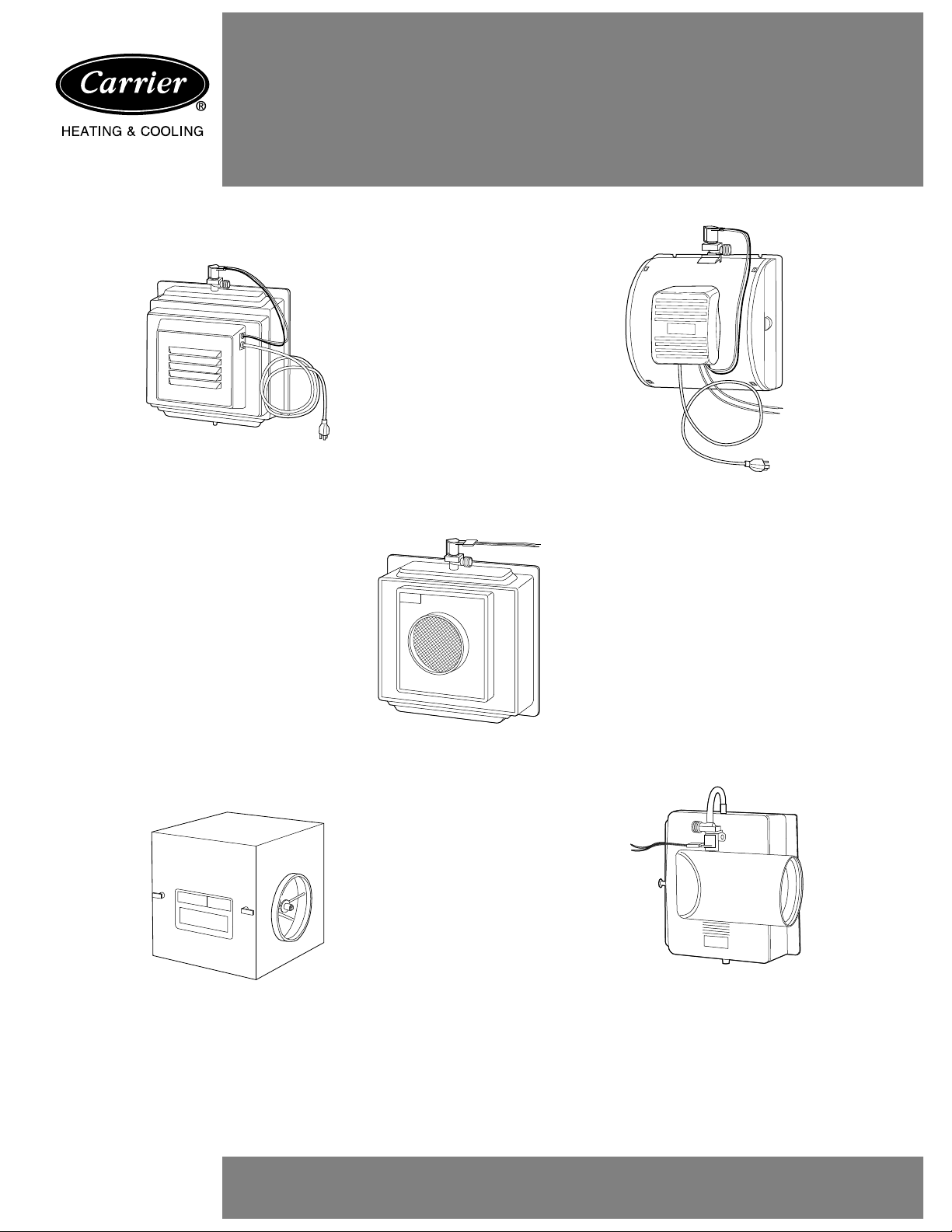
Model HUMCCLFP1025-A--
Fan-Powered Humidifier
Model HUMCCLBP2018-A--
Model HUMCCSFP1016-A--
Fan-Powered Humidifier
Bypass Humidifier
Model HUMCCWTR2019-A--
Water-Saver Bypass Humidifier
NOTE TO INSTALLER: This manual should be left with the equipment user.
Model HUMCCSBP2017-A--
Bypass Humidifier
Page 2
REFRESHING MOISTURE . . .
AS NATURE INTENDED
Congratulations on your excellent choice and sound investment
in this addition to your home comfort system.
Your humidifier represents both the latest in engineering development and the culmination of many years of experience from
one of the most reputable manufacturers of comfort systems.
Your new unit is among the most energy-efficient and reliable
home humidifiers available today. To assure its dependability,
spend a few minutes no w with this booklet. Learn about the operation of your humidifier and the small amount of maintenance
it takes to keep it operating at peak efficiency .
With minimal care, your humidifier will provide you and your
family with moist, spring-fresh air — from season to season and
year to year.
YOUR HOME HUMIDIFIER
Y OUR HOME CAN BE DRIER THAN DEATH VALLEY
During the heating season, your home can become uncomfortably dry. This is because cold winter air holds very little moisture. When outdoor air is warmed to a v erage room temperature,
its relative humidity falls to even lower levels. Refer to Table 1
for a comparison of the levels of relati ve humidity for a fe w sample environments.
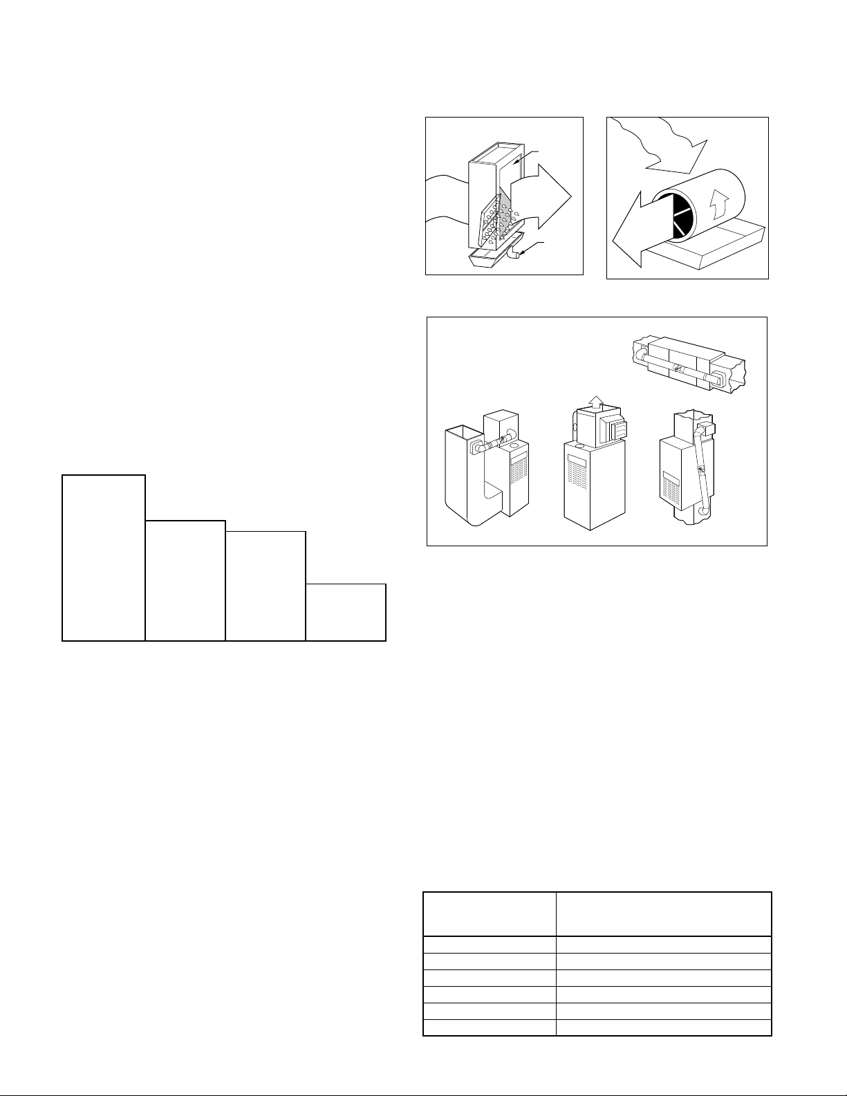
Table 1 — Relative Humidity Comparison
the large evaporator pad. Hot, dry air from the furnace passes
through the pad and absorbs the water . Then, this moisture-laden
air is distributed throughout the house via the ductw ork. See Fig.
1, 2, and 3.
HUMIDIFIED
AIR
DRY
AIR
DRY
EVAPORATOR
PAD
HUMIDIFIED
AIR
AIR
DRAIN
Fig. 1 Fig. 2
TYPICAL
INSTALLATIONS
HEATED HOME
RECOMMENDED
RELATIVE
HUMIDITY
SAHARA
DESERT
DEATH
VALLEY
HEATED HOME
AVERAGE
35% 25% 23% 5-15%
Parched air can cause the wood used in the construction of your
house and furnishings to dry , crack, and split. Draperies and upholstery may age prematurely. Annoying static electric shock
and cling are more prevalent. Your throat, nasal passages, sinuses, and skin are more susceptible to irritating dryness. You
may even have to set the thermostat higher than otherwise necessary — just to feel warm.
MOISTURE MAKES A REFRESHING DIFFERENCE
Proper humidity control can alleviate problems caused by e xcessive dryness. Furnishings and fabrics take on a more lustrous
appearance. Houseplants thrive. Static electricity is signifi cantly
reduced in a properly humidified home. Your family will breathe
more easily and find relief from the cool, drafty feeling commonly experienced in ov erly dry homes. The additional moisture
supplied by your humidifier may enable you to reduce the temperature setting on your thermostat — without any loss of indoor
comfort.
HOW Y OUR HUMIDIFIER WORKS
Your humidifier adds water molecules to the air inside your
home. Although the rate of humidification is variable, it may
exceed one-half gallon of water per hour. That’s a healthy drink
for a dry household. The typical process of humidification begins when water flows through the humidifier valve and soaks
Fig. 3
OPERA TING YOUR HUMIDIFIER
Y our ne w humidifier is designed to operate as part of your home
heating system. It will perform at maximum efficiency if these
recommendations are followed:
•
The humidifier is controlled by a humidistat. Adjust the
humidistat setting according to the outside temperature. Refer
to Table 2 as a general guide. If after several days, the air in
your home seems too moist, lower the humidistat setting. Condensation on single-pane windows indicates excessive moisture. If the air is too dry, increase the setting. Dry throat and
nasal passages indicate dry air.
•
All models come with a humidistat. Continuous blower oper ation provides for constant humidification. It may also contribute to greater personal comfort because continuous blower
operation minimizes temperature differences throughout the
home. Furthermore, a system equipped with an electronic air
cleaner offers the added benefit of full-time air filtration.
Table 2 — Humidistat Settings
OUTSIDE
TEMPERATURE
(°F)
–20 15
–10 20 (LOW)
–0 25
10 30
20 35
30 40 (MED)
RECOMMENDED
HUMIDISTAT SETTING
(% RELATIVE HUMIDITY)
2
Page 3
•
Supply- and return-air grilles should not be blocked by items
such as drapes, furniture, and toys. Restricted airflow reduces
the efficiency of the humidifier , as well as that of the whole comfort system.
•
The humidifier unit must be properly maintained on a regular
basis.
STARTUP PROCEDURES
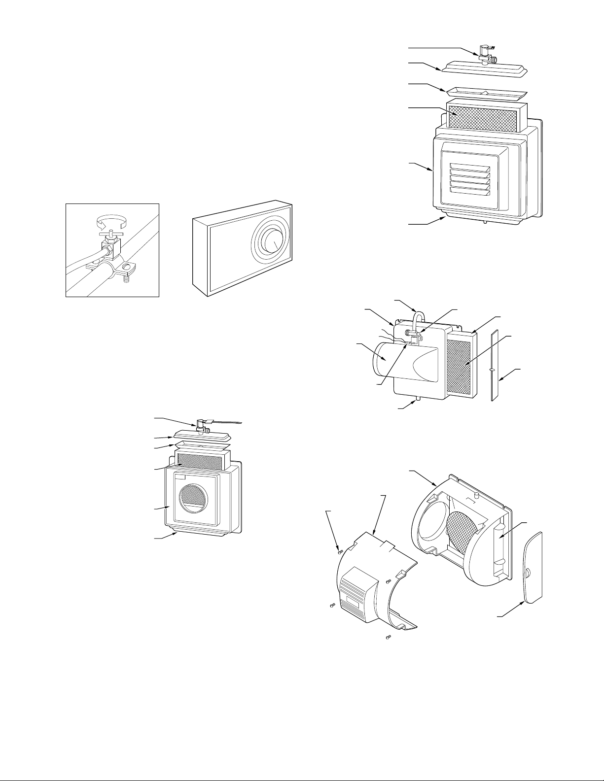
1. Open the saddle valve on the w ater supply line. (See Fig. 4.)
Set humidistat to the desired relative humidity. (See Fig. 5
and T able 2.)
2. Turn the furnace on and adjust the thermostat to a high temperature setting. Be sure that the furnace blower is operating.
3. Check to see if water is flowing into the humidifi er.
HUMIDISTAT
Fig. 4 — Saddle Valve Fig. 5
SOLENOID VALVE
DISTRIBUTOR COVER
DISTRIBUTOR PAN
EVAPORATOR PAD
CABINET
BOTTOM ACCESS PANEL
Fig. 7 — Model HUMCCLP1025-A--
CABINET
INLET
SOLENOID VALVE
DISTRIBUTOR PAN
•
On a Model HUMCCLBP or Model HUMCCLFP humidifier, loosen the thumbscre w that holds the distributor cover to the
top of the cabinet. Lift up the distributor cover slightly to make
certain that water is flowing from the solenoid valve into the
distributor pan. Do not lift the cover off the cabinet more than
1 in. when water is flowing. (See Fig. 6 or 7 according to the
model you own.)
SOLENOID VALVE
DISTRIBUTOR COVER
DISTRIBUTOR PAN
EVAPORATOR PAD
CABINET
BOTTOM ACCESS
PANEL
Fig. 6 — Model HUMCCLBP2018-A--
•
On a Model HUMCCSBP humidifier, gently pull the latch
that secures the access door. Remove the door. Check to see if
water is flowing from the solenoid v alve into the e vaporator pad.
(See Fig. 8.)
•
On a Model HUMCCSFP humidifier, open the side door or
the front cover. If the front cover is opened, hold the pad assembly in place. Check to see if water is flowing from the solenoid
valve into the distributor pan. (See Fig. 9.)
•
On a Model HUMCCWTR unit, look through the window on
front of the unit to see that the evaporator pad is rotating and
water is flowing. (See Fig. 10.)
The Model HUMCCWTR is controlled by a float valv e. T urning
off the furnace will not affect the water flow until float level is
achieved. (See Fig. 11.)
DUCT HOUSING
EVAPORATOR PAD
SIDE ACCESS DOOR
RECTIFIER
DRAIN
Fig. 8 — Model HUMCCSBP2017-A--
CABINET
FRONT COVER
SCREWS (4)
PAD ASSEMBLY
SIDE ACCESS DOOR
Fig. 9 — Model HUMCCSFP1016-A--
4. Turn off the furnace. When the blower stops, look into the
humidifier to make sure the water is not flowing into the
unit.
5. Replace the cover assembly and f asten securely.
6. Now, turn the furnace on and set the thermostat for desired
room temperature.
3
Page 4

4
SHUTDOWN PR OCEDURES
T o shut do wn your humidifier, close the saddle valve on the water line. Then turn off the humidistat. When set to the OFF position, the humidistat shuts off the electrical po wer to the solenoid
valve on the humidifier.
NOTE:
If your home comfort system includes cooling, be sure
the water supply to your humidifier is
turned off
during the cooling season. Close the damper located in the bypass duct if one
is installed. If your humidifier is a Model HUMCCWTR, drain
and clean the water pan as described in cleaning procedures.
PERFORMING ROUTINE MAINTENANCE
With the proper maintenance and care, your humidifi er will operate economically and dependably . Maintenance can be accomplished easily by referring to the following directions. Ho we ver ,
before performing any maintenance, consider these important
safety precautions:
•
DISCONNECT ALL ELECTRICAL POWER TO THE
HUMIDIFIER AND FURNACE BEFORE PERFORMING
ANY SERVICE OR MAINTENANCE TO AVOID PERSONAL INJURY.
BEARING RETAINER
CABINET
PAD
PAN
Fig. 10 — Model HUMCCWTR2019-A--
NOTE: THERE MAY BE MORE THAN 1 ELECTRICAL
DISCONNECT SWITCH.
•
ALTHOUGH SPECIAL CARE HAS BEEN TAKEN TO
MINIMIZE SHARP EDGES IN THE CONSTRUCTION OF
YOUR HUMIDIFIER, BE EXTREMELY CAREFUL WHEN
HANDLING PARTS OR REACHING INTO THE UNIT TO
AVOID PERSONAL INJURY.
Y our humidifier has been designed for easy disassembly to simplify cleaning and servicing. Your unit must be kept clean to
maintain its efficiency.
Regular inspection allows you to determine the cleaning schedule best suited to your humidifier’s operating conditions. The
frequency for required maintenance will depend most upon the
available w ater supply . In areas where hard w ater and high mineral content are prev alent, more frequent cleaning and servicing
may be required.
At minimum, the humidifier will need to be cleaned at the beginning of every heating season.
CLEANING PROCEDURES
Models HUMCCLBP, HUMCCSBP, HUMCCLFP, and
HUMCCSFP
1. Turn off all electrical power to the humidifier and furnace
or fan coil.
2. Turn off the humidifier’s w ater supply. (See Fig. 4.)
3. Disassemble the humidifier.
•
T o disassemble a Model HUMCCSBP humidifi er , gently pull
the latch that secures the access panel. Remove the door and
slide the evaporator pad assembly out of the unit. (See Fig. 8.)
•
To disassemble either a Model HUMCCLBP or Model
HUMCCLFP humidifier, first remove the water supply connection to the solenoid valve. Next, remove the screw that
holds the distributor cover to the cabinet, and lift off the cover.
Disconnect the drain line from the sump and loosen the
thumbscrew(s) holding the sump to the cabinet. Remove the
sump. Remove evaporator pad assembly. (See Fig. 6 or 7,
according to the model you own.)
•
To disassemble a Model HUMCCSFP, the pad assembly can
be removed from the side access door or the front cover. When
removing the side door , lift the pad assembly up by holding the
tabs and slide the assembly out. When remo ving the front co ve r
on Model HUMCCSFP, disconnect the quick connects to the
solenoid valve, unscrew the 4 screws to the front cover, snap
loose the top and bottom catches, and lay the front cover aside.
Once the front cover is off, lift the pad assembly up and twist it
out. The pad assembly consists of 4 parts; the distributor pan,
frame, sump, and the evaporator pad. Pull the distributor pan
apart from the frame and the ev aporator pad can be removed. Do
not force the evaporator pad in or out without removing the distributor pan as this will distort the pad.
4. Clean the humidifier’ s external components.
•
If your humidifier is a Model HUMCCSBP humidifier, wash
the access door and outlet drain portion of the cabinet. Make
sure the drain is open.
•
If your humidifier is a Model HUMCCLBP or HUMCCLFP,
wash the distributor cov er, sump cover, and cabinet. Be sure the
inlet ports are open and clean. Then, clean the sump with a solution of detergent and water.
5. Clean the internal components of your humidifier . Wash the
distributor pan with a mild detergent and warm water. Be
sure holes and slots in the pan are clean and unobstructed.
Wash the evaporator pad assembly in a detergent solution.
If there are scale deposits on the pad, soak it in ordinary
household vinegar. If the pad is covered by a hea vy deposit
of scale, or if the local water supply has high sulfate or calcium content, replace the pad with a new one. Contact your
dealer for replacement part.
6. Reassemble your humidifier.
7. Turn on the electrical power and water supplies. Refer to
the startup procedures.
Model HUMCCWTR
1. Turn off all electrical power to the humidifier and furnace
or fan coil.
2. Turn off the humidifier’s w ater supply. (See Fig. 4.)
3. Drain water from the unit. Place a pail underneath the drain
plug located on the bottom of the humidifier cabinet. Lift
the tab on the drain plug and remove the plug. Allow all
water to drain from the unit. (See Fig. 12.)
Page 5
5
4. Remove the front door from the humidifier. Rotate the
latches one-half turn, then pull the door forward.
5. Remove and inspect the evaporator pad assembly. Lift the
bearing from its retainer. (See Fig. 10.) Pull the assembly
away from the motor to disengage the assembly shaft from
the motor coupling. Remove assembly through the access
opening.
Inspect the evaporator pad. If the pad is heavily loaded with
scale, or if the local water has a high sulfate content, replace the
pad. Contact your dealer for replacement part.
NOTE: For best performance, the evaporator pad should be
replaced before each heating season.
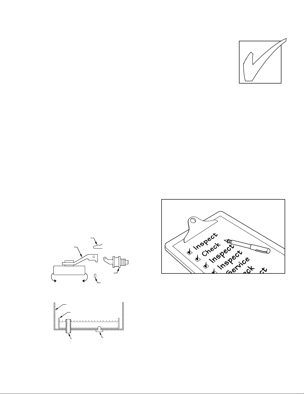
6. Inspect the float assembly. Remove the float arm from the
valve body by sliding out the pin and lifting off the float
arm. (See Fig. 11.) Inspect the rubber valv e seat located inside the float arm. If the seat appears to be nicked or worn,
invert the seat or replace it with the spare valve seat located
on the float arm. Inspect the water opening in the valve
body. If the opening is clogged, use a pin to remove the
obstruction. Remove any accumulated deposits from the
valve body and float arm.
7. Clean the water pan and unit cabinet. T ilt the w ater pan and
lift it from the unit. Wash the pan with warm, soapy water.
Flex the pan to loosen accumulated scale. Wash the unit interior, removing any accumulated deposits. Inspect the
drain line to insure that no blockage has occurred. Clean as
required. (See Fig. 12.)
8. Reassemble your Model HUMCCWTR humidifier. Reinsert the water pan and drain plug. Ensure that the overflow
tube is inserted into the hole at the bottom of the cabinet.
Attach the float arm to the valve body by aligning the holes
on both parts and reinserting the pin.
the pin.
The float arm should have free up-and-do wn mov e-
Do not force or bend
ment. Install the evaporator pad assembly. Ensure that the
square shaft engages the motor coupling and that the bearing washer is located inside the bearing retainer. Turn the
water on. Adjust float by rotating until water covers inside
of foam drum. Attach the access door and turn the latches.
PIN
BEFORE YOU REQUEST A “SERVICE CALL’’
BEFORE YOU CALL FOR SERVICE, CHECK FOR
THESE EASILY SOL VED PROBLEMS:
•
Check the main power disconnect
switch. Verify that the circuit breakers are on and that fuses have not
blown. If you must reset breakers or
replace fuses, do so only once. Contact your servicing dealer for assistance if the breakers trip or the fuses
blow a second time.
•
If the humidity level is too lo w , check the humidistat setting.
Confirm that the saddle valve is turned on. Check the evaporator pad, and clean or replace the pad as necessary . Check w ater
level in Model HUMCCWTR.
•
Check for sufficient airflow. Check the furnace filter or electronic air cleaner for excessiv e accumulations of dirt. Check for
blocked return- or supply-air grilles. Be sure grilles are open
and unobstructed.
•
If water drips from the humidifier, check the drain hose for
kinks or obstructions. If your unit is a Model HUMCCWTR,
dripping may indicate that the float valv e requires adjustment.
If your comfort system still fails to operate properly, contact
your servicing dealer for troubleshooting and repairs. Specify
your apparent problem, and state the model and serial numbers
of your equipment. (You should have them recorded where
noted in this booklet.) W ith this information, your dealer may be
able to offer helpful suggestions o ver the phone, or save v aluable
time through knowledgeable preparation for the service call.
FLOAT ARM
VALVE
BODY
HIGHER
Fig. 11 — Float Arm Removal
Fig. 12 — Cleaning Water Pan and Unit Cabinet
LOWER
HUMIDIFIER HOUSING
WATER PAN
OVERFLOW TUBE
VALVE SEAT
DRAIN PLUG
9. Turn on electrical power supplies. Refer to startup procedures listed on page 3.
REGULAR DEALER MAINTENANCE
In addition to the routine maintenance that you perform, your
humidifier should be inspected regularly by a properly trained
service technician. The inspection (preferably each year, but at
least every other year) should include the following:
•
Routine inspection of the humidifier. Cleaning, if necessary.
Cleaning or replacement of the evaporator pad as required.
•
A check of all electrical wiring and connections.
•
A check of water connections to the unit.
•
Operational check of the complete comfort system to determine actual working condition. Necessary repair and/or adjustment should be performed at this time.
Your servicing dealer may offer an economical service contract
that covers seasonal inspections. Ask for further details.
Page 6

6
Page 7

7
Page 8

Record the model and serial numbers of your new humidifi er in
the following spaces. This information, along with the other
ready-reference facts requested below, may be required if you
should ever need information or service.
Model No._________________________________________
Serial No. _________________________________________
Date Installed ______________________________________
Dealer Name_______________________________________
Address___________________________________________
City ______________________________________________
State ____________________ Zip_____________________
T elephone _________________________________________
TO OBTAIN INFORMATION ON PARTS: Consult your installing dealer or the classified section of your local telephone directory under the
“Heating Equipment’’ or “Air Conditioning Contractors & Systems’’ heading for dealer listing by brand name.
Have available the Model No., Series Letter, & Serial No. of your equipment to ensure correct replacement part
Carrier Corporation Indianapolis, IN 46231
Manufacturer reserves the right to discontinue, or change at any time, specifications or designs without notice and without incurring obligations .
Copyright 1998 Carrier Corporation Form: OMHUM-1 Replaces: OM49-9 Printed in the U.S.A. 7-98 PC 101 Catalog No. 03HU-MC0
 Loading...