

Page 1
30HR,HS070-160
HEATING & COOLING
Flotronic Plus Reciprocating Liquid Chillers
Controls Troubleshooting Guide
Alf Model E Units Have Microprocessor Controls
and Electronic Expansion Valves
CONTENTS
Page
SAFETY
FLOTRONIC PLUS CONTROL SYSTEM ..... l-4
Generat ..................................... 1
Features .....................................
. PROCESSOR MODULE ...................
l LOW-VOLTAGE RELAY MODULE .........
. EXV
VALVE) DRIVER MODULE ...............
. KEYBOARD AND DISPLAY MODULE .....
. ELECTRONIC EXPANSION VALVE ........
l THERMISTORS ...........................
. CAPAClTY CONTROL ....................
CONTROL SEQUENCE .....................
Off Cycle ....................................
Start-Up ....................................
Capacity Control ............................
l SEQUENCE ...............................
Unit Shutdown ..............................
Complete Unit Stoppage
Single-Circuit Stoppage .....................
Lag Compressor Stoppage ...................
Restart Procedure ...........................
l GENERAL POWER FAlLURE ..............
l BLOWN FUSE
DISCONNECT ............................
l LOW WATER TEMPERATURE
CUTOUT..................................
l AUXILIARY INTERLOCK .................
l OPEN CONTROL
. FREEZE PROTECTION ....................
a HIGH-PRESSURE SWITCH ................
l LOSS OF CHARGE SWITCH ...............
. COMPRESSOR DISCHARGE
TEMPERATURE SWITCH .................
. OIL SAFETY SWITCH .....................
CONTROLS OPERATION .................. .5-l I
Accessing Functions and Subfunctions. ......
Qisplay Functions ...........................
a SUMMARY DISPLAY .....................
. STATUS FUNCTION ......................
. TEST FUNCTION ........................
Programming Functions
.
SERVlCE
l SET POINT FUNCTION ..................
l SCHEDULE FUNCTION ..................
TROUBLESHOOTING .....................
Checking Display Codes ....................
l OPERATING MODE CODES ..............
. ALARM CODES
Quick Test .................................
Electronic Expansion Valves ................
l CHECKOUT PROCEDURE ...............
l EXV OPERATION ........................
Thermistors ................................
l LOCATION ..............................
l SENSOR REPLACEMENT ................
Modules ....................................
CONSlDERATlONS
(ELECTRONK
IN
POWER FEED
EXPANSION
CIRCUlT
................ 1
.....................
FUSE ..........
....................
FUNCTION ....................
.........................
4,5
10
1
11
11
11
12-26
12
12
12
14
19
19
21
22
22
22
23
SAFETY CONSIDERATIONS
Installation, start-up and servicing of this equipment
can be hazardous due to system pressures, electrical
components and equipment location.
Only trained, qualified installers and service mechanics
2
2
2
2
2
3
3
3
4
4
4
4
5
5
5
5
5
5
5
5
5
5
5
5
5
5
5
5
5
5
5
I
should install, start-up and service this equipment.
When working on the equipment, observe precautions
in the literature, tags, stickers and labels attached to the
equipment and any
l Follow all safety codes.
0
Wear safety glasses and work gloves.
l Use care in handling, rigging and setting bulky
other
safety precautions that apply.
equipment.
l Use care in handling elcetronic components.
ELECTRII~ SHOCK HAZARD.
Open all remote disconnects before
servicing this equipment.
This unit uses a micreprocessor-based electronic
control system.
190
not use jumpers or other tools
to short out components, bypass or otherwise depart
from recommcndcd procedures. Any short-to-
ground of the control board or accompanying wiring
may destroy the electronic modules or electrical
component.
FLOTRONIC PLUS CONTROL SYSTEM
General
feature microprocessor-based electronic controls and an
electronic expansion valve (EXV) in each refrigeration
circuit.
The Flotronic Plus control system cycles compressors
and compressor unloaders to maintain the selected leav-
ing water temperature set point. It automatically positions the EXV to maintain the specified refrigerant
superheat entering the cylinders of the compressor.
Safeties are continuously monitored to prevent the unit
from operating under unsafe conditions. A scheduling
function, programmed by the user, controls the unit
occupied/ unoccupied schedule. The control also operates
a Quick Test program that allows the operator to check
input and output signals to the microprocessor.
The control system consists of a processor module
(PSIO), low-voltage relay module (DSIO), electronic
expansion valve (EXV), EXV driver module (DSIO),
keyboard and display module (HSIO) and thermistors to
provide analog inputs to the microprocessor. The soft-
ware resides in the PSIO.
-
The 30HR,HS Flotronic Plus chillers
Page 2
-
Features
-
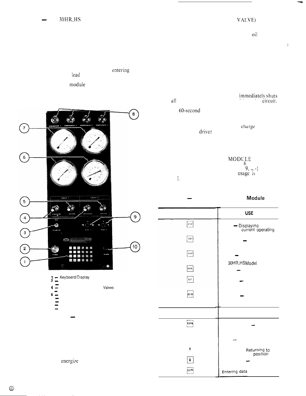
The 30HR,HS control panel is shown in
Fig. 1.
PROCESSOR MODULE - This module contains the
operating software and controls the operation of the
machine. It continuously monitors information received
from the various temperature thermistors and communicates with the relay module to increase or decrease the
active stages of capacity. The processor module also
controls the EXV driver module, commanding it to open
or close each electronic expansion valve in order to maintain approximately 20 F of superheat entering the
cylinders of each of the
Iead
compressors, Information is
transmitted between the processor module and the relay
module, EXV driver moduIe and keybuard display
module through a 3-wire communications bus.
8
0
EXV (ELECTRONIC EXPANSION VALVE) DRIVER
MODULE -- The EXV driver module operates the electronic expansion valves (based on commands from the
processor) and monitors the status of the
oi1
pressure
switches and the refrigerant Ioss of charge switches.
If the loss of charge switch opens due to a low refrigerant charge, the EXV driver module detects a zero
voltage condition in the loss of charge switch electrical
circuit and communicates this information to the processor module. The processor module immediately shuts
down all compressors in the affected refrigeration circuit.
During operation, if the EXV driver module detects
zero voltage in the oil pressure switch electrical circuit
for 45 consecutive seconds (due to an open oil pressure
switch), it communicates this information to the processor module. The processor module immediatelvshuts
down ali compressors in the affected refrigeration circuit.
At start-up, if the oil pressure switch has not closed by the
end of a 60-second time period the EXV driver module
senses this and the processor module immediately shuts
down all compressors in the affected refrigeration circuit.
If a shutdown occurs due to loss of
cftarse
or low oil
pressure, the EXV driver module communicates this to
the processor module and the processor module locks the
compressors off in the affected refrigeration circuit.
The proper fault code(s) will appear on the display
whenever a safety switch opens.
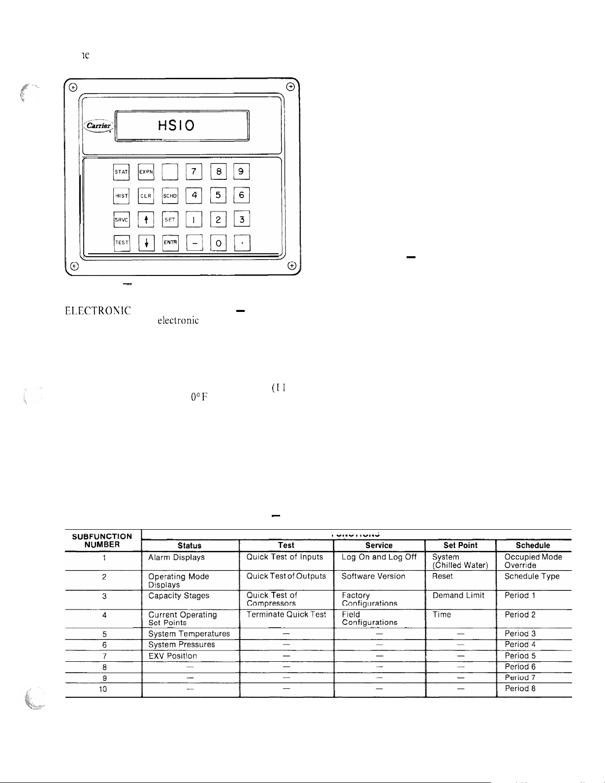
KEYBOARD AND DISPLAY MODKLE - (Fig. 2)
This device consists of a keyboard with Cr function keys,
5 operative keys, 12 numeric keys (0 to 9, 11 -) and an
alphanumeric g-character LCD. Key
in Table
1.
usage ii;
explained
.:.
9
0
IO
0
I - Keyboard/Display Module
2 -
Control Power ON Light
3 - RUN/STANDBY Switch
4 -
Discharge Pressure Gage
5 - Suction Pressure Gage Valves
6 -
Suction Pressure Gages
7 - Discharge Pressure Gages
8 - Compressor ON Lights
9 - Control Circuit Fuses
-
Alarm Light
10
Fig. 1 - Control Panel
Valves
LOW-VOLTAGE RELAY MODULE -- This module
closes contacts to energize compressors, solenoid valves
and unloaders. It also senses the condition of the com-
pressor safeties and transmits this information to the
processor module.
Table 1 - Keyboard and Display Madule
FUNCTION
KEYS
SCHD
0
OPERATIVE
KEYS
EXPN
El
CLR
q
t
q
4
El
ENTR
0
Key Usage
LOSE
Status - Displayjng diagnostic
codes and current operating
information about the machine
Quick Test - Checking inputs
and outputs for proper
operation
History - This key appears on
the keyboard, but is not used on
the 30HR,HS
Service - Entering specific
unit configuration information
Set Point - Entering operating
set points and day/time
information
Schedule - Entering occupied/
unoccupied schedules for unit
operation
Expand Display - Displaying a
non-abbreviated expansion of
the display
Clear - Clearing the screen of
all displays
Up Arrow previous display posItIon
Down Arrow - Advancing to
next display position
Modei
USE
Rtjturnipg to
E machines
-
2
Page 3
Each function has one or more subfunctions as shown At initial start-up the valve position is initialized to 0.
in Table 2. These functions are defined in greater detail After that, the microprocessor keeps accurate track of the
in t K Controls Operation section of this book.
valve position in order to use this information as input for
the other control functions.
The control monitors the superheat and the rate of
change of superheat to control the position of the valve.
The valve stroke is very large; this results in very accurate
control of the superheat.
The electronic expansion valve is also used to limit the
maximum saturated suction temperature to 55 F (12.8 C)
to keep from overloading the compressor during high
cooler water temperatures. This allows the unit to start
with very warm water temperatures.
THERMISTORS ~ The electronic control uses 7 thermistors to sense temperatures used to control the operation of the chiller. Sensors are listed in Table 3.
Fig. 2 - Keyboard and Display Module
ELECTROWIC EXPANSION VALVE ~ The micro-
processor controls the electronic expansion valve through
the EXV driver module. Inside the expansion valve is a
linear actuator stepper motor. To control the stepper
motor’s position, the thermistor in the cooler and the
thermistor in the lead compressor in each circuit are used
to maintain a 20 F (1 I C) difference. Because the compressor sensor is after the compressor motor, which adds
approximately 15 F (8.3 C) superheat, the 20 F (1 I C)
control temperature results in
U”F
to 5 F (2.8 C) superheat leaving the cooler. This improves the performance of
the cooler.
CAPACITY CONTROL ~ The control cycles compressors and alternately loads and unloads cylinders to
give capacity control steps as shown in Table 4. The unit
controls leaving chilled water temperature. Entering
water temperature is used by the microprocessor in determining the optimum time to load and unload, but is not a
control set point.
The chilled water temperature set point can be automatically reset by the return temperature reset or space
and outside air temperature reset features.
Table 2 - Function and Subfunctions
FUNCTIONS
Page 4
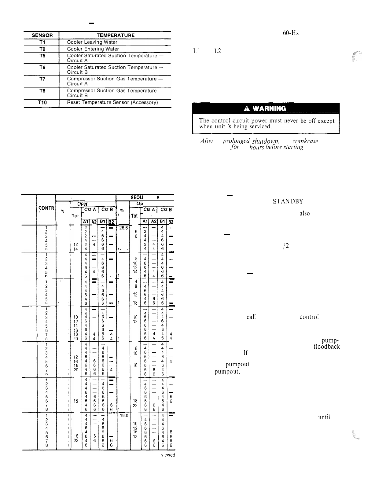
Table 4 - Capacity Control Steps
UNIT
:ONTR
30HR
STEPS
30HS
070
080
090
100
110
120,
160
140
NOTE: Circuits and
from front of unit.
Table 3 - Thermistors
SEQUENCE A
c
?r Cylinders
-
%
Cap.
EiiqTm-
Compr
42
6
a
10
E
a
10
12
14
16
4
a
10
12
16
18
8
1:
::
a
10
:;
hi
22
a
10
12
16
1%
22
24
a
10
12
16
:;
24
-
4
4
-
-
-
4
4
-
-
-
6
6
-
-
4
4
t
-
6
:
6
2
14.3
42.9
57.2
71.2
85.7
100.0
4
25.0
50.0
62.5
75.0
87.5
100.0
22.2
44.4
55.5
66.7
88.8
100.0
4
20.0
40.0
50.0
60.0
70.0
80.0
90.0
::
100.0
4
18.2
36.3
45.4
54.5
72.7
81.8
90.9
100.0
4
16.6
33.3
41.6
50.0
66.7
75.0
91.6
100.0
4
19.0
38.0
47.6
57.0
69.0
78.6
90.4
100.0
compressors designated from ieft to right when viewed
82
-
-
-
-
-
-
-
-
-
-
-
-
-
-
-
t
-
-
-
4
4
-
-
-
-
:
-
-
E
-
%
Cap.
2&.6
42.9
57.2
71.2
85.7
00.0
25.0
50.0
62.5
75.0
87.5
00.0
22.2
44.4
55.5
66.7
88.8
‘00.0
20.0
40.0
50.0
60.0
70.0
80.0
90.0
100.0
18.2
36.3
45.4
54.5
63.6
72.7
90.9
t 00.0
16.6
33.3
41.6
50.0
66.7
75.0
91.6
100.0
19.0
38.0
47.6
57.0
69.0
78.6
90.4
100.0
ENCE 3
er Cylinders
c
-
zlzqxi7
rot.
4
:
10
12
14
4
1:
13
14
16
ii
10
12
16
18
4
a
10
12
14
16
18
20
4
1:
12
14
16
20
22
4
a
10
12
16
:;
24
4
8
iif
::
22
24
Compr
B2
-
-
-
-
-
-
-
-
-
-
-
-
4
-
-
-
-
-
-
CONTROL SEQUENCE
The control power (115-l-60 for 60-Hz units; 230-l-50
for 50-Hz units) must be supplied directly from a separate
source through a code-approved fused disconnect to the
Ll
and L2 terminals of unit power teminal block.
NOTE: There is no switch or circuit breaker; only fuses. If
the control power feed is live, so is the circuit.
Crankcase heaters are wired into the control circuit.
They are always operative as long as control circuit
power is on even though unit may be off because of
safety device action. Heaters are wired so they are on only
when their respective compressors are cycled off.
A,f’tor
should be on
a prnlonged shutdoun, the
,for
24
hours hqfbre starting
crankcause
the unit.
heaters
When power is supplied to control circuit, unit is ready
for operation providing all safety devices are satisfied,
interlocks are closed and instructions on warning labels
have been followed.
If schedule function is used, refer to page 11 for details
on control operation.
Off Cycle - During unit off cycle when the RUN;
STANDBY switch is in the STANDBY position, the
crankcase heaters and the control system are energized.
The electronic expansion valves are
also
energized.
(NOTE: The control circuit power must be on at all times
even when the main unit power is off.)
Start-Up - When the RUN/STANDBY switch is
moved from the STANDBY to the RUN position and
there is a call for cooling, after l-l /2 to 3 minutes have
passed the first compressor will start unloaded, The first
circuit to start may be circuit A or B due to the automatic
lead/ lag feature.
Capacity Control - (See Table 4.) The rate at which
the compressors are turned on will depend on the leaving
water temperature difference from the set point, the rate
of change of leaving water temperature, the return water
temperature and the number of compressor stages on.
The control is primarily from leaving water temperature
and the other factors are used as compensation.
SEQUENCE -- On a
4
4
:
starts the initial compressor. The control will randomly
select either circuit A or B. The liquid line solenoid valve
remains closed for 10 seconds after the initial compressor
on that refrigeration circuit starts. This permits a pump-
caiI
for cooling, the controI system
out cycle at start-up to minimize refrigerant floodback
to the compressor. If the compressor in that refrigeration
circuit has run in the 15 minutes before the call for
4
4
4
cooling, the pumpout cycle is bypassed.
After pumpout, the liquid line solenoid valve opens and
the electronic expansion valve starts to open.
The electronic expansion valve will open gradually to
provide a controlled start-up to prevent liquid floodback
:
6
6
to the compressor. Also during this period, the oil pressure switch will be bypassed for one minute.
As additional cooling is required, the control system
will ramp up through the capacity steps available until the
load requirement is satisfied. As capacity steps are added
compressors are brought on line, alternating between the
:
E
lead and lag refrigerant circuits. As explained previously,
the speed at which capacity is increased or decreased is
controlled by the temperature deviation from the set
point and the rate of change in the chilled water
temperature.
4
Page 5
When the second or lag refrigeration circuit is started,
the circuit will go through a lo-second pumpout unless
the circuit has been operating in the 15 minutes prior to
this start.
Upon load reduction, the control system will unload
the unit in the reverse order of loading until the capacity
nearly matches the load. Each time the lead compressor is
cycled off, the liquid line solenoid valve and electronic
expansion valve will be closed for 10 seconds prior to
compressor shutdown to clear the cooler of liquid
refrigerant.
Unit Shutdown - To stop unit, move the RUN/
STANDBY switch to the STANDBY position. Any
refrigeration circuit that is operating at this time will
continue for 10 seconds to complete the pumpout cycle.
(Lag compressors stop immediately, lead compressors
run for 10 seconds.)
Complete Unit Stoppage can be caused by any of
the following conditions:
a.
general power failure
b.
blown fuse in control power feed disconnect
C.
open control circuit fuse
d.
RUN/STANDBY switch moved to STANDBY
e.
freeze protection trip
low flow protection trip
f.
open contacts in chilled water flow switch (optional)
g.
h.
open contacts in any auxiliary interlock. (Terminals
TBI-13 and TBJ-14, jumpered from factory, are in
series with the control switch. Opening the circuit
between these terminals places the unit in STANDBY
mode, just as moving the control switch to STANDBY
would. Code26 will appear as the operating mode
in the status function display. The unit cannot start
if these contacts are open, and if they open while unit
is running, it will pump down and stop.
Single Circuit Stoppage can be caused by the
following:
a. open contacts in
lead compressor discharge gas
thermostat
b. open contacts in loss of charge switch
c. open contacts in oil safety switch
d. open contacts in lead compressor high-pressure switch
Stoppage of one circuit by a safety device action does
not affect the other circuit. Besides stopping compressor(s), all devices listed will also close liquid line
solenoid valve for that circuit.
Lag Compressor Stoppage can be caused by the
following:
a. open contacts in discharge gas thermostat
b. open contacts in high-pressure switch
LOW WATER TEMPERATURE CUTOUT Move
RUN/ STANDBY switch to STANDBY, then back to
RUN. Restart is automatic.
AUXILIARY INTERLOCK ~- Automatic restart after
condition is corrected.
OPEN CONTROL CIRCUIT FUSE
“--
Replace fuse.
Unit will restart automatically.
FREEZE PROTECTION - Unit will automatically
restart when leaving water temperature is 6 degrees F
above the leaving water set point.
HIGH-PRESSURE SWITCH, LOSS OF CHARGE
SWITCH, COMPRESSOR DISCHARGE TEMPERATURE SWITCH AND OIL SAFETY SWITCH
-- Move the RUN;‘STANDBY switch to STANDBY,
then back to RUN. Unit will restart automatically.
CONTROLS OPERATION
Accessing Functions and Subfunctions
-
Table 5. Refer also to Table 2, which shows the 5 functions (identified by name) and the subfunctions(identified
by number). Table 6 shows the sequence of all the elements in a subfunction.
Display Functions
SUMMARY DISPLAY ~ Whenever the keyboard has
not been used for 10 minutes, the display will auto-
matically switch to an alternating summary display. This
display has 4 parts, shown below, which alternate in
continuous rotating sequence.
Display
TUE
12:45
MODE 26
Expansion
TODAY IS TUE, TIME IS
UNIT STANDBY
12:45
1 STAGES NUMBER OF STAGES IS 1
2 ALARMS
2 ALARMS DETECTED
STATUS FUNCTION ~ The status function shows the
current status of alarm (diagnostic) codes. capacity
stages, operating modes,
chilled water set point. all
measured system temperatures, superheat values, pressure switch positions and expansion valve positions.
These subfunctions are defined below. Refer to Table 6
for additional information.
[r-r-j
pq
(Alarms) Alarms are messages that one or
more faults have been detected. Each fault is assigned a
code number which is reported with the alarm. (See
Table 7 for code definitions.) The codes indicate failures
that cause the unit to shut down, terminate an option
(such as reset) or result in the use of a default value
as set point.
Up to 3 alarm codes can be stored at once. To view
If stoppage occurs more than once as a result of any
of the above safety devices, determine and correct the
cause before attempting another restart.
Restart Procedure, after cause for stoppage is
corrected.
GENERAL POWER FAILURE ~ Unit will restart
automatically when power is restored.
BLOWN FUSE IN POWER FEED DISCONNECT
Replace fuse. Restart is automatic.
them in sequence, press
m m
to enter the alarm
displays and then press key to move to the individ-
ual alarm displays. Press
EXPN)
after a code has been
I
dis-
played and the meaning of code will scroll across the
screen.
When a diagnostic (alarm) code is stored in the display
and the machine automatically resets, the code will be
deleted. Codes for safeties which do not automatically
reset will not be deleted until the problem is corrected
~
and the machine is switched to STANDBY, then back
to RUN.
5
confinued on page IO
Page 6
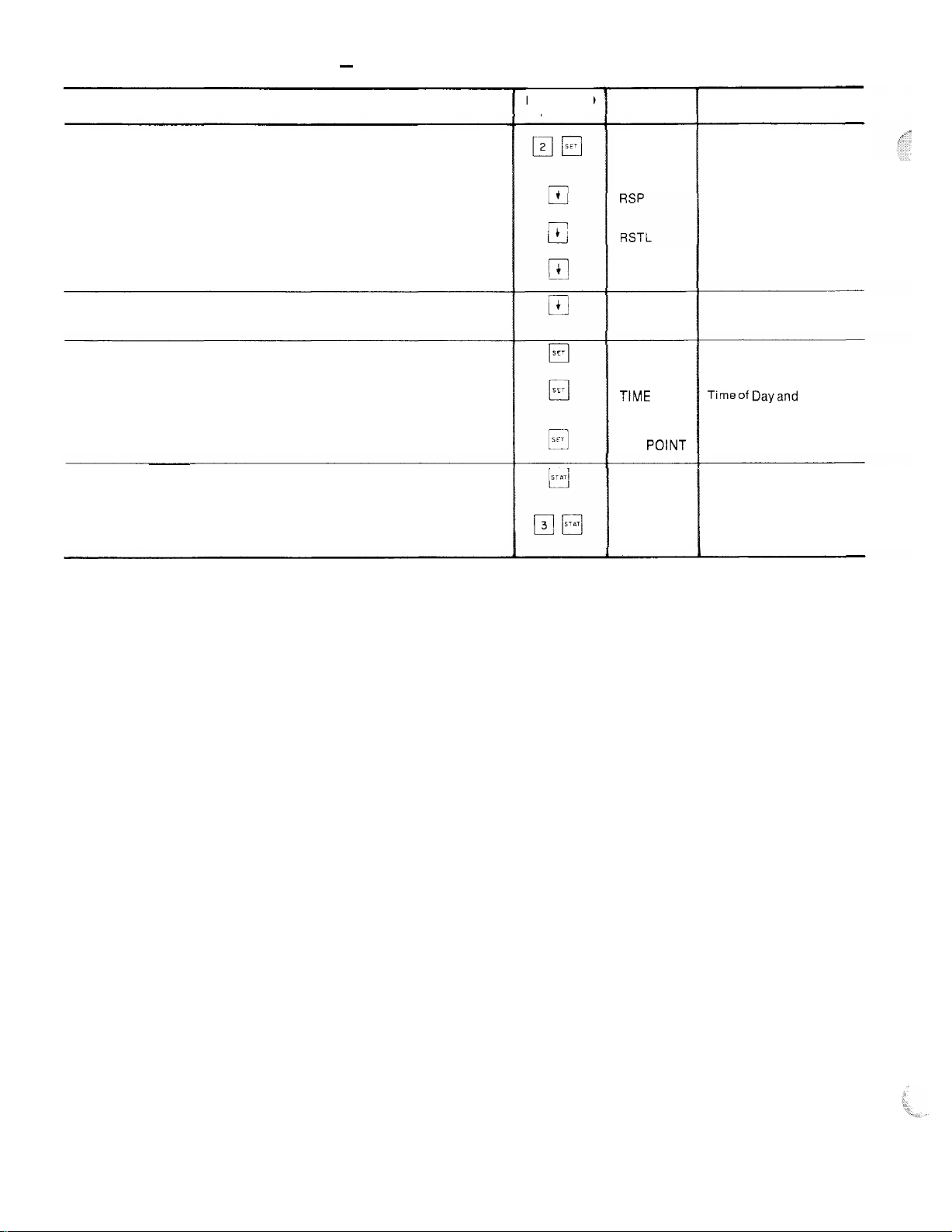
Table 5 - Accessing Functions and Subfunctions
OPERATION
To access a function, press the subfunction number and the
function name key. The display will show the subfunction group
To move to the other elements, scroll up or down using the arrow
keys
When the last element in a subfunction has been displayed, the first
element wilt be repeated
To move to the next subfunction, it is not necessary to use the
subfunction number; pressing the function name key will advance
the display through all subfunctions within a function and then back
to the first
To move to another function, either depress the function name key
for the desired function (display will show the first subfunction)
or
Access a particular subfunction by using the subfunction number
and the function name key
KEYBOARD
ENTRY
DISPLAY
RESET
RSTR
RSP
DEMAND
TtME
SET
POINT
X ALARMS
STAGES
DESCRIPTION
Reset Set Points
Reset Set Point
Reset Limit
Reset Ratio
Reset Set Point
Demand Limit Set Points
Timeof Dayand Day
of Week Display
System Set Points
X Alarms Detected
Capacity Stages
Page 7
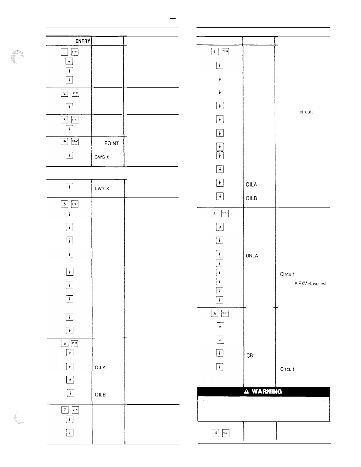
Table 6 - Keyboard Directory
STATUS
KEYBOARD ENTI DISPLAY KEYBOARD ENTRY
X ALARMS
ALARM X
ALARM X
ALARM X
MODE
MODE X
STAG ES
X STAGE
SET POlNT
If unit is in dual set point mode the set point currently in effect
is displayed. ’
TEMPS
LWT X
i
0
i
G
4
17
+
c
$
Cl
EWT X
SSTA X
CGTA X
SHA X
SSTB X
CGTB X
SHB X
RST X
PRESS
LCSA X
OILA X
LCSB X
OILB X
ANALOG
EXVA X
EXVB X
COMMENT
Current alarm displays
Alarm 1
Alarm 2
Alarm 3
Current operating
mode displays
Mode 1
Capacity stages
Stage number
Current operating
set point
Leaving chilled water
set point
Leaving water
temperature
System temperatures
Cooler leaving water
temp
Cooler entering water
temp
Saturated suction temp
circuit A
Compressor suction
gas temperature
circuit A
Superheat temp
circuit A
Saturated suction temp
circuit B
Compressor suction
gas temperature
circuit B
Superheat temp
circuit B
Reset temperature
Systems pressures
Circuit A loss of charge
switch
Circuit A oil pressure
switch
Circuit B loss of charge
switch
Circuit B oil pressure
switch
System analog values
Circuit A EXV valve
position
Circuit B EXV valve
position
4
q
+
El
c
r=
c
0
+
0
c
0
4
cl
c
ill
t
0
4
El
4
cl
4
0
4
c
During test of compressors, each compressor will start and
run for 10 seconds. Compressor servicevalves and the liquid
line valve must be open. Energize compressor crankcase
heaters for 24 hours prior to performing compressor tests.
p-Jm
QUICK TEST
DISPLAY COMMENT
INPUTS
LWT X
EWT X
SSTA X
CGTA X
SSTB X
CGTB X
RST X
LCSA X
LCSB X
OILA X
OILB X
OUTPUTS
SLDA X
SLDB X
UNLA X
UNLB X
EXVAO X
EXVAC X
EXVBO X
EXVBC X
COMP
CA1 X
CA2 X
CBI X
CB2 X
END TEST
Factory/field test of
inputs
Leaving water
temperature
Entering water
temperature
Saturated suction temp
circuit A
Compressor suction
gas temp circuit A
Saturated suction temp
circuit B
Compressor suction
gas temp circuit B
Reset temperature
Loss of charge switch
circuit A
Loss of charge switch
circuit B
Oil pressure switch
circuit A
Oil pressure switch
Circuit B
Factory/field test of
outputs
Circuit A liquid line
solenoid test
Circuit B liquid line
solenoid test
Unloader A test
Unloader B test
Circurt A EXV open test
Circuit AEXVclosetest
Circuit B EXV open test
Circuit B EXV close test
Factory/field test of
compressors
Circuit A compressor 1
test
Circuit A compressor 2
test
Circuit B compressor 1
test
Circuit B compressor 2
test
Leave quick test
I
7
Page 8
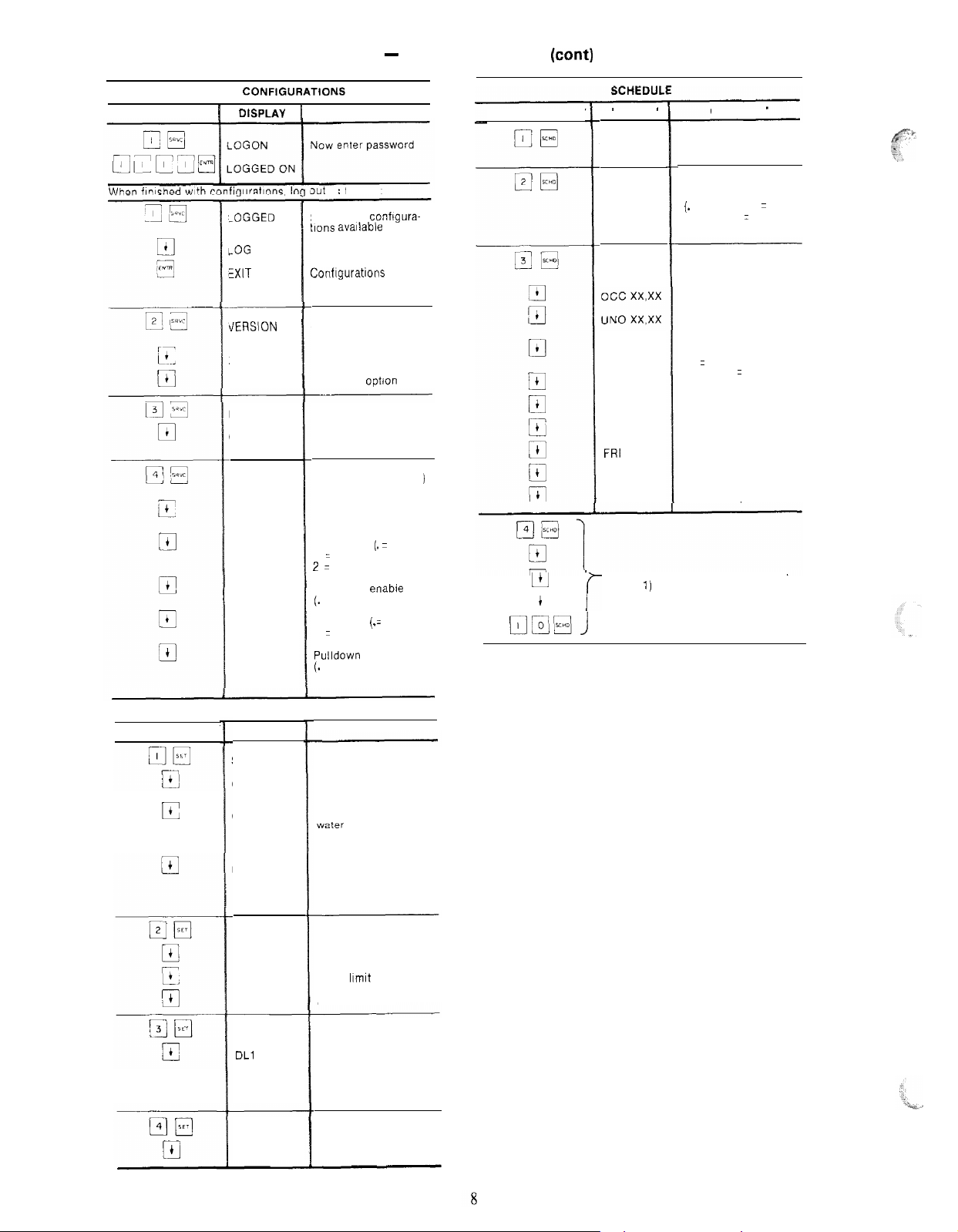
SERVICE CONFIGURATtONS
KEYBOARD ENTRY 1 DtSPLAY
Table 6 - Keyboard Directory (cant)
i
COMMENT
KEYBOARD ENTRY
DISPLAY
COMMENT
-0GGED ON \
-0G OFF
KXIT
LOG /
tiERSION
xxx
xxx
FACT CFG
COMP X
FFD CFG
UNLS X
RSTP X
LDSH X
FLD X
PLDN X
3ut
as
follows.
Shows that confrgura-
tlons
avaIlable
Conflgurations now
again password
protected
Software version
number
Software version
Language
Factory configuration
Number of unloaders
(enter number, or. for
zero)
Field configuration (
= entry codes
Number of unloaders
(enter number)
Reset type (. = none
1 = return water,
2 = space or outside air)
Load shed enable
(.
= disable, 1 = enable)
Ftuid type
1 = brine)
Pulldown enable
(.
= disable, 1 = enable)
optJon
(.=
water,
)
’
OVRD X
SCHTYP X
PERIOD 1
MON X
TUE X
WED X
THU X
FRI
SAT x
SUN X
LL
4
q
r
Entering number of
hours to extend
Schedule Type
( ) = entry codes
(.
= inactive, 1 = single
set point, 2 = dual set
point)
Define time schedule
period 1
Start of occupied time
Return to unoccupied
time
Monday flag
( ) = entry codes
(1 = yes, . = no)
X
Sunday flag
Time periods 2-8 (same elements as
period I)
KEYBOARD ENTRY
E
q
SET POINT
COMMENTDISPLAY
SET POINT
cwso x
cwsu x
MSP X
RESET
RSP X
RSTL X
RSTR X
DEMAND
DLl X
DL2 X
TIME
DAY 00.00 Current setting
System set points
Occupied chilled water
set point
Unoccupied chilled
water set point appears
only when unit is in
dual set point mode
Modified chilled water
set point (read only).
Set point determined
by reset function
Reset set points
Reset set point
Reset limit
Reset ratio
Demand limit set points
Demand limit set
point
Demand limit set
point 2
Page 9
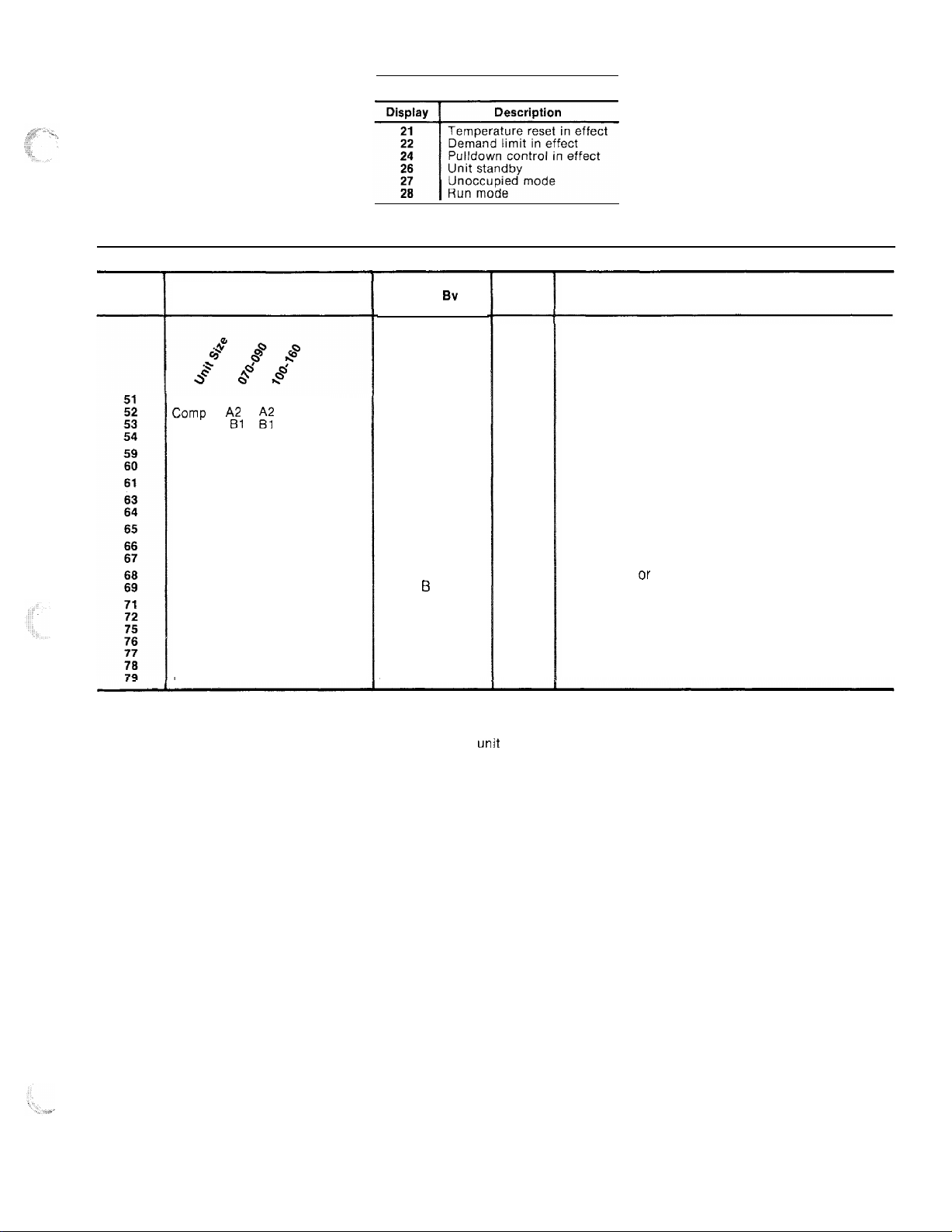
Display
Description
Table 7 - Display Codes
OPERATING MODES
ALARMS
Action
Taken
Control
Sv
Reset
Method
Probable Cause
Comp Al Al
Camp
Comp Bl
Comp
Loss of charge circuit A
Loss of charge circuit B
Low cooler flow
Low oil pressure circuit A
low oil pressure circuit B
Freeze protection
High suction superheat circuit A
High suction superheat circuit B
Low suction suoerheat circuit A
Low suction superheat circuit B
Leaving water thermistor failure
Entering water thermistor failure
Cooler thermistor failure circuit A
Cooler thermostor failure circuit B
Comp thermistor failure circuit A
Comp thermistor failure circuit B
Reset thermistor failure
NOTES:
1. Freeze protection trips at 35 F (1.7 C) for water and 6 degrees F (3.3 degrees C) below set point
for brine units. Resets at 6 degrees above set point.
2. All auto. reset failures that cause the unit to stop will restart the
corrected.
3. All manual reset errors must be reset by moving the control switch to STANDBY then to RUN.
4. Valid resistance range for thermistors is 363,000 ohms to 216 ohms.
A2
ii:
Failure
Failure
Failure
B2 Failure
Circuit A shut off
Comp shut off
Circuit B shut off
Comp shut off
Circuit A shut off
Circuit B shut off
Unit shut off
Circuit A shut off
Circuit B shut off
Unit shut off
Circuit A shut off
Circuit B shut off
Circuit A shut off
Circuit 6 shut off
Unit shut off
Use default value
Circuit A shut off
Circuit B shut off
Circuit A shut off
Circuit B shut off
Stop reset
Manual
Manual
Manual
Manual
Manual
Manual
Manual
Manual
manual
Auto.
Manual
Manual
Manual
Manual
Auto.
Auto.
Auto.
Auto.
Auto.
Auto.
Auto.
unit
when the error has been
High pressure switch trip or high discharge gas temp
switch trip, on when it is not supposed to be on. Wiring
error between electronic control and compressor relay.
Low refrigerant charge, or loss of charge pressure switch
failure.
No cooler flow or reverse cooler flow
Oil pump failure or low oil level, or switch failure.
Low cooler flow
Low charge or EXV failure, or plugged filter drier.
EXV failure ar cooler thermistor error.
Thermistor failure, or wiring error, or thermistor not
connected to input terminals.
9
Page 10

p-JB
(Modes) The operating mode codes are dis-
(Position) The position subfunction displays
played to indicate the operating status of the unit at a
given time. (See Table 7).
The modes are explained in the Troubleshooting sec-
tion on page 12.
[3-i
F]
ity stage number, from 1 to 8. See Table 4 for compressor
loading sequence to enter the STAGES subfunction,
depress
stage number.
leaving water temperature and the Leaving chilled water
set point. If the unit is programmed for dual set point,
the chilled water set point currently in effect (either
occupied or unoccupied) will be displayed. If reset is in
effect, the unit will be operating to the modified chilled
water set point. This means that the leaving water temperature may not equal the chilled water set point. The
modified
the status function. To read the modified chilled water
set point, refer to the Set Point Function section, page 1
To enter the set point subfunction, depress
then use the
water set point followed by the leaving water temperature.
EKI
displays the readings at temperature sensing thermistors.
To read a temperature, enter then scroll to
the desired temperature using
the order of the readouts.
(Stages) This subfunction displays the capac-
m F]
chrlled
STAT
(Temperature) The temperature subfunction
and use the
(Set Point) This subfunction displays the
water set point will not be displayed in
$
key to display the leaving chilled
III
m
key to display the
i
key. Table 6 shows
cl
pqz-],
the current position of the electronic expansion
in steps:
Fully Open (760)
Operating Position ( 160 Minimum)
Fully Closed, Circuit Shut Down (0)
TEST FLJNCTlOh’ - The test operates the Quick Test
diagnostic program.
mode, the test subfunctions will energize the solenoid
valves, unloaders, electronic expansion valves and compressors. The solenoids and unloaders will energize for 3
minutes. The expansion valve will travel to fully open in
one test and to fully closed in the next. The compressors
will energize for 10 seconds. The subfunctions are ex-
plained below. Refer to Table6 for all the elements in
the subfunctions.
p-j
i;;;;i ~-
1-q m -
except for compressors.
[-Y-j
T;;;;i
k1 I:ESTI ~
uu
1.
NOTE: The Quick Test energizes the alarm light and
alarm relay. They will remain energized as long as the
unit is in Quick Test.
To reach a particular test, enter its subfunction number
and then scroll to the desired test with the
test can be terminated by pressing
after a test has started will advance the system to the next
test, whether the current one is operating or has timed
out. Once in the next step, you may start the test by
pressing
While the unit is in Quick Test, you may access another
display or function by depressing the appropriate keys;
however, the unit will remain in the Quick Test function
until
for 10 minutes, the unit will automatically leave the
Quick Test function.
-
Tests the compressors.
ENTR
El
TEST
q cl
When the unit is in STANDBY
Displays the status of all inputs.
Tests the outputs from the processor,
Takes the unit out of Quick Test.
) . Pressing
cl
or advance past it by pressing h .
is entered, or, if the keyboard is not used
valves
4
key. A
G
cl
El
4
17-l
m
status of the oil pressure and loss of charge switches. The
display will show LOW or KRM for the oil pressure
switch and LOW or SAFE for loss of charge switch.
(Pressure) This subfunction displays the
IO
Page 11

Programming Functions
SERVICE FUNCTION - The service function allows
the operator to verify factory configurations and read
or change field configurations. The service subfunctions
are listed below. (See Table 6 for details.)
The operator must use this subfunction to
log on before performing
to log off after completing
pJ@-
language option.
(number of compressors).
pq m .-..
for number of unloaders and reset type and to enable the
machine for load shed, pulldown, or brine operation.
NOTE: Thenf
Used to verify software version and
Used to verify factory configurations
Usrd to read or change field configuration
key is used to enable or turn on certain
any other subfunction,
service subfunctions.
and
If single
in the schedule function,
the display
set point.
c. The modified chilled water set point is determined by
the microprocessor as a result of the reset function,
and is displayed for reference only; it cannot be set
or changed by the operator. If reset is not in effect, the
modified set point will be the same as either the occupied or unoccupied chilled water set point, according
to how the schedule function has been programmed.
ratio
reset
funct
3
cl
4
0
set point or inactive
show the
will
Displays the reset, reset Limits, and reset
set points, These set points are not accessible when
type has been configured for NONE in the service
ion.
SET
il
Displays the demand limit set points.
--Displays time of day and day of week.
sched ule has been
when + is depressed
then
ii
modified chilled water
selected
functions; the
SET POINT FUNCTION -- Set points are entered
through the keyboard. Set points can be changed within
the upper and lower limits, which are fixed. The ranges
are listed below.
Chilled
Water Set Point
Water:
40
to 70 F (4.4 to 21 C)
Brine (Special Order Units):
15
to 70 F (-9.4 to 21 C)
Rc~set
Set Point
0 to
95 F (-17.8 to 35 C)
Reset Limit
0to80 F (-17.8 to 26.7 C)
Reset Ratio
0 to 100%
Ilemand Limit Set
Step I Capacity Reduction:
0% to
Step 2 Capacity Reduction:
0% to
Set points aregrouped in subfunctions as follows:
a.
The first
set point.
b. The next value to
schedule function h
If dual set point-has been selected, the next set point
after
L-J
chilled water set point; this will be followed by the
modified chilled water set point.
I
key is used to disablethesefunctions.
cl
key is pressed the display will show 00.00.
Poiot5
100%
100%
Displays chilled water set points.
value shown is the occupied chilled water
be
displayed depends on
.as
been programmed. (See
+
has been pressed will be the unoccupied
how the
below.)
SCHEDULE FUNCTION ~ This function provides a
means to automaticafly switch the chiller from an
occupied mode to an unoccupied mode. When using the
schedule function, the chilled water pump relay, located
in the unit control box, must be used to switch the chilled
water pump on and off. The chilled water pump relay will
start the chilled water pump but the compressors will not
run until the remote chilled water pump interlock contacts are closed and the leaving chilled water temperature
is above set point. If a remote chilled water pump interlock is not used. the first compressor will start (upon a
call
for cooling) approximately one minute after the
chilled water pump is turned on.
The schedule
ngle
set point. or
si
When the schedule is configured for inactive, the
chilled water pump relay remains energized continuously
but is not used since the chiller is usually controlled by
remote chilled water pump interlock contacts.
When the schedule is set for single set point operation,
the
chilled
the chiller is in the occupied mode regardless of whether
the chiller is running. When the chiller is in unoccupied
mode, the chilled water pump relay will not be energized.
When the schedule is set for dual set point, the chilled
water pump relay will be energized continuously, in both
occupied and unoccupied modes. The occupied mode
places the occupied chilled water set point into effect; the
unoccupied mode places the unoccupied chiller water set
point into effect.
The schedule consists of from one to 8 occupied time
periods, set by the operator. These time periods can be
flagged to be in effect or not in effect on each day of the
week. The day begins at 00.00 and ends at 24.00. The
machine will be in unoccupied mode unless a scheduled
time period is in effect. If an occupied period is to extend
past midnight, it must be programmed in the following
manner: Occupied period must end at 24:00 hours
(midnight); a new occupied period must be programmed
to begin at
The time schedule can be overridden to keep the unit
in the occupied mode for one, 2, 3 or 4 hours on a onetime basis.
function can be programmed
dual
set
pntnt
operation.
water pump relay will be energized whenever
0O:OO
hours.
for
inactive,
I1
Page 12

TROUBLESHOOTING
If necessary, review the Flotronic Plus Control System,
Control Sequence, and Controls Operation sections
found in this book. Tables 5 and 6 show how to use the
keyboard/display module to access functions and subfunctions. (These procedures are also explained in the
3OHR,HS Installation, Start-Upand Service Instructions
along with examples and details on using the control
features. A copy of the installation instructions should be
kept handy while troubleshooting.)
Checking Display Codes - To determine how the
machine has been programmed to operate, check the
diagnostic information ( and operating
If the schedule is holding the machine off when it is
needed, set the schedule for inactive mode until the
schedule can be properly reprogrammed. (See the Schedule Function section of the Installation, Start-Up and
Service Instructions.) The override feature can also
-be
used to temporarily place the unit in occupied mode.
Enter
(1 to 4), then press
then the number of hours to override
SCHD
,
cl
EWR
.0If the unit is in override and
you wish to cancel it, enter zero hours in the same manner.
Run Mode (28)
To enter the MODES subfunction, depress
and use the
4
key to determine if more than one
p-j Fj
mode displays
(
If no display appears,
follow the procedures in Troubleshooting, Modules,
page 23. If the display is working, continue as follows:
1. Note all the alarm codes displayed
(
2. Note all the operating mode codes displayed
(ppq).
3. Note the leaving chilled water temperature set point
in effect and the current leaving water temperature
If the machine is running, compare the “in effect”
leaving water temperature set point with the current
water temperature. Remember that if reset is in effect,
they may be different because the machine is operating
to the modified chilled water set point. If the current
temperature is equal to the set point but the set point
is not the one desired, recall that if dual set point has
been selected in the schedule function, there are 2 set
points to which the machine can be operating. Check
the programming of the schedule function to see if the
occupied or unoccupied set point should be in effect.
OPERATING MODE CODES - Following is an
explanation of the operating mode codes:
Temperature Reset (21) ~ In this mode, the unit is using
temperature reset to adjust the set point, and the unit is
controlling to the modified set point. This means that the
leaving water temperature may not equal the chilled water
set point. The set point can be modified based on return
water, outside air temperature or space temperature.
Demand Limit (22) - This indicates that the capacity of
the unit is being limited by the demand limit control
option. The unit may not be able to produce the desired
leaving water temperature because the unit may not load
to full capacity.
Pulldown Control (24) -- If this option is in effect and
the cooler water temperature is warm, extra stages will
not be added if the water temperature leaving the cooler is
decreasing faster than I0 F (0.6 C) per minute.
Standby (26) ~ The unit is being held in the standby
mode either because the RUN /STANDBY switch is
onen
or a set of relay contacts in series with the KUN/
STANDBY switch is open (contacts wired between
terminals TBl-13 and TBI-14).
Unoccupied Mode (27) - In dual set point schedule, this
mode means the machine is operating to the unoccupied
set point. In single set point schedule, this mode shuts
down the unit in the same manner as “Unit Standby.”
mode applies.
Do not attempt to bypass, short or modify the
control circuit or electronic boards in any way to
correct a problem. This could result in component
failures or a hazardous operating condition.
ALARM CODES - The following is a detailed description of each alarm code error and the possible cause.
Manual reset of an alarm is accomplished by moving the
RUN/STANDBY switch to STANDBY, then back
to RUN.
Codes 5 l-54, Compressor Failure - If the DSIO relay
module relay or control relay feedback switch opens
during operation of a compressor, the microprocessor
will detect this and will stop the compressor, energize
the alarm light, and display a code of 5 1 to 54, depending
on the compressor. The compressor will be locked off;
to reset, use the manual reset method.
If the lead compressor in a circuit is shut down, all the
other compressors in the circuit will be stopped and
locked off. Only the alarm code for the lead compressor
will be displayed,
The microprocessor has also been programmed to
indicate a compressor failure if the feedback terminal on
the 253 terminal strip receives voltage when the com-
pressor is not supposed to be on.
Following are possible causes for this failure:
High-Pressure Switch Open - The high-pressure switch
for each compressor is wired in series with the 24-volt
power that energizes the compressor control relay. If the
high-pressure switch opens during operation the com-
pressor will stop and this will be detected by the micro-
processor through the feedback terminals.
Discharge
Gas Thermostat ~ The discharge gas thermo-
stat switch in each compressor is also wired in series with
the 24-volt power that energizes the control relay (CR).
If the switch opens during operation of the compressor,
the compressor will be stopped and the failure will be
detected through the feedback terminals.
DSIO Module Failure ~ If a DSIO relay module relay
fails open or closed, the microprocessor will detect this
and lock the compressor off and indicate an error.
Wiring Errors - If a wiring error exists causing the CR
or feedback switch not to function properly, the micro-
nrocessor
1
Processor
will indicate an error.
(PSIO)
Failure -
If the hardware that
monitors the feedback switch fails or the processor fails
to energize the relay module relay to ON, an error may
be indicated.
: I
t.,
12
Page 13

NOTE: The control does not detect circuit breaker
failures. If a circuit breaker trips on the lead compressor
in a circuit, a
low oil
pressure failure will be indicated;
on the other compressors, no failure will be indicated.
Checkout P~-o~etiur~
(Codes 51-54) - Shut off the main
power to the unit. Turn on control power, then step
through the Quick Test to the proper compressor number
(i.e., failure code S3 is
step
CBT). Next, energize the
step. If the step works correctly, then the failure code
is due to:
. HPS
l
l
l
open
Ix-r open
Mj~placcd fu&
back wire from 2H5 strip to 293 strip
Ground wire and 24-volt feeds reversed on one or more
points on
2.t.3.
The 24-volt ground wire (brown)jumps
terminals 2, 4, 6 and 8. Feeds from compressors Al,
A2, Bl and 82 connect to pins I, 3, 5 and 7.
The processor closes the contacts between 255 ter-
minals 12 and 1 I to start the
cc3mprwsor.
(See Fig. 3.) The
safeties shown to the right of 2.15 must be closed for
power to reach the compressor
the feedback input (terminal t
Failure of power to terminal t
255 1 I and I2 should be
closed
c<)ntroX
relay (CR 1) and
~I”I 2,13).
OLI
2J3 when contacts
wilt
cause
a code 5 1 alarm.
Terminal 2 on 293 is the other leg of the compressor Al
feedback channel. It is connected to the 24-volt ground.
Code 59 and 60, Loss of Refrigerant Charge ~ A loss-of-
charge switch is connected to the high-pressure side of
the refrigerant system. The microprocessor monitors this
switch directly; if it opens, all the compressors in the
circuit will be locked off, the alarm will be energized and
the display code will appear when the alarm display is
accessed. To reset, use the manual reset method (move
the RUN/STANDBY switch to STANDBY, then back
to RUN).
Following are some possible causes for this alarm:
f,n\a> RejPigerant
Charge - If the system refrigerant
charge is very low, the microprocessor will detect this
through the switch and indicate the error.
StzYtch
Failure - If the switch f&s open, the micro-
processor will detect this and indicate an error.
Wiring Error - If there is a wiring error that causes an
open circuit, the microprocessor
wikk
treat this as an open
switch and indicate an error.
Proc~esssr
Board Failure - If the hardware in the processor module fails in a manner that the switch cannot
be read properly, an error may be indicated.
Code 61, No Cooler
Flow
-
The microprocessor contains logic that prutects the cooler against loss of cooler
flow.The cooler entering and leaving water temperature
sensors are used for this purpose. The leaving thermistor
is located in the leaving water nozzle and the entering
sensor is located in the first cooler baffle space in close
proximity to the cooler tubes as shown in Fig. 4. When
there is no cooler water flow and the compressors are
operating, the leaving water temperature thermistor will
indicate no temperature change. But the temperature of
the entering water will drop rapidly and the entering
water thermistor will detect this. When the entering water
temperature drops to 5 F (2.8 C) below the leaving water
temperature,
alf
the compressors will stop and code
no. 61 will be displayed. To correct, use manual reset
method (after cooler water Row is resumed).
The error will be caused either by no cooler flow or
if the water is flowing in the wrong direction through the
cooler or if the thermistors have been interchanged.
Fig. 3 - Compressor Al Control Wiring (Typical)
Code 63 and 64, Low Oil Pressure ~~ A low oil pressure
switch is installed on the lead compressor in each circuit.
If the switch opens during operation of the compressor,
all the compressors in the circuit will be shut off, the alarm
light will be energized and the appropriate display code
shown. The switch will be bypassed for one minute during
start-up and for 45 seconds during normal operation. The
manual reset method must be used to reset this safety.
Possible causes for failure are:
Loss of’ Oil
Pres.sute -
If the oil pressure is below 5 &
psig (34.5 & 6.9 kpa), the switch will open.
.S\i’itch Failure -
If the switch fails open, a failure will be
indicated.
Compwssor is
wiring
Errur -
not
running.
If a wiring error exists that causes an
open circuit, an error will occur.
Pm~essov
Mod&
Faifure ~
If the hardware on the
processor module fails in a manner that the switch cannot
be read properly, an error may be indicated.
Code 65, Cooler Freeze Protection ~ If the leaving water
temperature is below 35 F (1.7 C) for a water chiller or
is 6’F (3.3 C)
below
the set point for brine applications,
all compressors wiil be stopped. This safety will auto-
matically reset when the water temperature is 6 F (3.3 C)
above the set point.
The causes for this failure are usually due to low cooler
flow, or extremely rapid load changes.
Code 66 and 67, High Suction Superheat - The micro-
processor contains the following logrc and
ifit
is satisfied,
all the compressors in the circuit will be stopped:
Suction superheat is greater than 75 F (4f.7 C), and
saturated cooler suction is
iess
than 55 F (12.8 C) and
these 2 conditions have been true for more than5 minutes.
To reset this, use the manual reset method.
Causes for this failure are:
IL);%’ R<fkigeranf C’hwge ~
A low refrigerant charge
will.
not allow the correct amount of refrigerant to be fed to
the evaporator, which will result in a high superheat.
Pbuggcd
Filter Drier
If the liquid line filter drier
-
becomes plugged, it can result in not enough refrigerant
being fed to the evaporator, which results in a high superheat failure.
EXY Failure - If the EXV fails to open enough to feed
the proper amount of refrigerant, the error will occur.
EXV
Dviveu
hardware that controls the EXVs fails, the
Moduk Failure ~ Xf the DSIO module
valve
will
not move.
1
13
Page 14

COOLER TUBE
LEAVING WATER
THERMISTOR..
Fig. 4 - Cooler Sensor Locations
SUCTION
,----CONNECTION
\
INLET
CONNECTION
ENTERING COOLER
WATER SENSOR
(T21
(T58T6)
Bau’
The~~isfor ~ Thermistors mis-located or out of
calibration.
Code 68 and 69, Low Suction Superheat
~‘--
if the following logic is satisfied, then all the compressors on the
circuit will be stopped.
Suction superheat is equal to 0°F
(OOC)
or the saturated suction is greater than 58 F (14.4 C) and either
condition has been true for more than 5 minutes.
Possible causes for this failure are a stuck electronic
expansion valve or thermistors mis-located or out of
calibration.
To reset, use the manual reset method.
Code 71 to 81, Thermistor Failure
~~~
If the measured
temperature of a thermistor is less than -60 F (-51 C)
(363,000 ohms) or greater than 240 F (116 C) (2 16 ohms),
the appropriate sensor error code will be displayed and
the unit will be stopped. The thermistor failures will
automatically reset. The following is a summary of
possible causes.
Thermistor Failure - A shorted or open circuit ther-
mistor will cause the failure.
Wiving Failure - A shorted or open circuit will cause
the failure.
P~oc~essnr
Module
Fczilure ~
If the circuitry in the pro-
cessor module fails, the error could occur.
NOTE: The reset thermistor is an optional thermistor
and is only used with outside or space temperature reset.
It will only be read by the processor if the unit is con-
figured for outside or space temperature reset.
The absence of a thermistor failure does not necessarily
mean that a thermistor is accurate. To determine
accuracy, the reading must be compared with a measure-
ment of the actual temperature to which the thermistor
probe is exposed.
Quick Test - The Quick Test feature allows the service
technician to individually test all the inputs and outputs
of the control system.
The test function operates the Quick Test diagnostic
program. When the unit is in STANDBY mode, the test
subfunctions will energize the solenoid valves, unloaders,
electronic expansion valves and compressors. The
solenoids and unloaders will energize for 3 minutes. The
electronic expansion valve will travel to fully open in one
test and to fully closed in the next. The compressors will
energize for 10 seconds. The subfunctions are explained
below. Refer to Table 6 for all the elements in the
subfunctions.
NOTE: The Quick Test energizes the alarm light and
alarm relay. They will remain energized as long as the unit
is in Quick Test.
To reach a particular test, enter its subfunction number
and then scroll to the desired test with the0+
test can be terminated by pressing
+
. Pressing
cl
key. A
+
El
after a test has started will advance the system to the
next test, whether the current one is operating or has
timed out. Once in the next step, you may start the test
by pressing
ENm
or advance past it by pressing h .
cl cl
While the unit is in Quick Test, you may access another
display or function by depressing the appropriate keys;
however, the unit will remain in the Quick Test function until
T;;i
H
is entered, or, if the keyboard is
not used for 10 minutes, the unit will automatically leave
the Quick Test function. See the following example:
14
Page 15

y$.
KEYBOARD
ENTRY RESPONSE
TEST
3
I
COMP
DISPLAY
q u
CAM
OFF
ENTR
q
CA1 ON
CAM
OFF
I
+
q
CA2 OFF
END TEST
COMMENTS
Factory field test of compressors
subfunction of test function
Circuit A, compressor 1 test
Pressing ENTR starts the test; when the
compressor should be running the
display shows CA1 on
If the test is allowed to time out, the
display will show
Pressing the down arrow key advances
the system to circuit A, compressor 2 test
If no other test is desired, exit quick test
CA1
off
Loss of charge and oil pressure switch tests show LOW
if the switch is
closed. The input channel can be tested by disconnecting
the switch and using a jumper to simulate a closed or open
circuit. (See Fig. 5.)
Note that the switch is read by the processor period-
ically, not continuously. When the switch position is
changed, it may take a few seconds before the display
changes.
The [q
outputs except for the compressor control outputs. (See
Fig. 6.)
The liquid line solenoid and unloader solenoid tests
will energize the output when
open
and NRM or SAFE if the switch is
Fi
subfunction will energize the control
ENTR
is pressed. It will
cl
Refer to Fig.
module in a panel is numbered ( I,
strip is labeled (52, 53, J4...). The terminal strip on the
machine schematic combines the module and strip
numbers.
module 2. The module numbers can be found on the com-
ponent arrangement label.
The
switch inputs. The thermistor tests display the temperature that the thermistor is reading. If the display and the
actual temperature do not match, the thermistor and the
input channel can each be checked.
To check the thermistor, disconnect its leads from the
PSI0
terminal (the entire connector can be pulled from
the
PSI0
resistance of the thermistor, then find the corresponding
temperature in Table 8.
This temperature should match the actual temperature
to which the thermistor is exposed.
The thermistor can be checked while connected to the
processor by measuring the voltage across its terminals
and finding the corresponding temperature in Table 8.
This method can only be used if it is certain that the
processor circuits are putting out the correct voltage. If
there is any doubt, the thermistor should be checked by
the resistance method.
The input channel can be tested by removing the
thermistor from the terminals and attaching a fixed
resistor with a value between 40,000 ohms and 400 ohms.
Refer to Table 8 and find the temperature that corresponds to that resistance; this temperature should
appear in the Quick Test display.
5,6
and 7 for specific control wiring. Each
For example, 2JJ is terminal strip 53 on
m
(;;;;I subfunction checks the thermistor and
by pulling the connector to the left). Read the
2,3,4...).
Each terminal
remain energized until either the
10 minutes have elapsed. When the processor energizes
the output reiay it will display the word ON on the right
side of the display.
The EXV open and close tests drive the EXV fully open
or fully closed. See The EXV Checkout Procedure for
more information. The display will read either zero steps
open or 760 steps open.
The 14 I;;;;]
control relays for 10 seconds and displays the compressor
status feedback.
The liquid line solenoid in the same circuit will energize for 10 seconds and the EXV will open 180 steps,
then close.
When control power reaches the compressor control
relay it also reaches the feedback terminal on terminal
strip 233 (see Fig. 7). When this occurs the display will
switch from OFF to UN. If the display changes but the
compressor does not start, check the control relay,
tactor, compressor circuit breaker, interconnecting
wiring, and the compressor motor.
If the display does not change, check the discharge gas
thermostat, high-pressure switch, condenser fan overload
(on 30HS, if used), continuity across the DSIO terminals
and interconnecting wiring.
To protect the compressors from repeated cycling, a
delay of one minute is required before the same compressor is retested.
The 4
Quick Test mode. Press
show EKD TEST; press
then shows END TEST again.
q
subfunction energizes the compressor
TEST
subfunctions take the unit out of the
a
14 H
ENS
cl
J key is pressed or
0
con-
and the display will
and the display blinks and
15
Page 16

THE PROCESSOR OPERATES
THESE CONTACTS
LC%%R&F
CIRCUIT
LOSS OF
CHARGE
CiRCUtT
A
B
24v
FEED
1
/
Fig. 5 - Compressor 24-V Control Circuit Wiring
(Simplified)
24v
DSlO
TERM ?$I.- STRIP
NEUTRAL
UNLOADER CKT. A
UNLOADER CKT.
LIQUID
LINE
SOLENOID CKT. A
LIQUID
LINE
SOLENOID CKT.
24V FEED 24V NEUTRAL
B
B
Fig. 6 - Pressure Feedback Circuit Wiring
(Simplified)
Fig. 7 - Auxiliary Components 24-V Control
Circuit Wiring (Simplified)
16
Page 17

Table 8a - Thermistsr Temperature
vs
Resistance and Voltage (English)
TEMPERATURE
VI
-25.0
-24.0
-23.0
-22.0
-21.0
-20.0
-19.0
-18.0
-17.0
-16.0
-15.0
-14.0
-13.0
-12.0
-11.0
-10.0
-9.0
-8.0
-7.0
-6.0
-5.0
-4.0
-3.0
-2.0
-1.0
0.0
1.0
2.0
3.0
4.0
5.0
6.0
7.0
8.0
9.0
10.0
11.0
12.0
13.0
14.0
15.0
16.0
17.0
18.0
19.0
20.0
21.0
22.0
23.0
24.0
25.0
26.0
27.0
28.0
29.0
30.0
31.0
32.0
33.0
34.0
35.0
36.0
37.0
38.0
39.0
40.0
41.0
42.0
43.0
44.0
45.0
46.0
47.0
48.0
49.0
50.0
51.0
52.0
53.0
54.0
55.0
56.0
57.0
VOLTAGE
DROP
(Y)
4.821
4.818
4.814
4.806
4.800
4.793
4.786
4.779
4.772
4.764
4.757
4.749
4.740
4.734
4.724
4.715
4.705
4.696
4.688
4.676
4.666
4.657
4.648
4.636
4.624
4.613
4.602
4.592
4.579
4.567
4.554
4.540
4.527
4.514
4.501
4.487
4.472
4.457
4.442
4.427
4.413
4.397
4.381
4.366
4.348
4.330
4.313
4.295
4.278
4.258
4.241
4.223
4.202
4.184
4.165
4.145
4.125
4.103
4.082
4.059
4.037
4.017
3.994
3.968
3.948
3.927
3.902
3.878
3.854
3.828
3.805
3.781
3.757
3.729
3.705
3.679
3.653
3.627
3.600
3.575
3.547
3.520
3.493
RESISTANCE
(OHIWS)
98009,6
94707.1
9152'8,5
88448.9
85485.5
82627.2
79870.6
77212.0
74647.9
72175.1
69790.3
67490.4
6,5272.4
63133.3
61070.3
59080.6
57161.7
55310.9
53525.8
51804.0
50143.2
48541.1
46995.6
45504.7
44066.3
42678.5
41339.3
40047.1
38800.0
37596.4
36434.7
35313.3
34230.7
33185.4
32176.2
31201.5
30260.1
29350.9
28472.5
27623.8
26803.7
26011.2
25245.1
24504.6
23788.7
23096.4
22426.9
21779.3
21152.8
20546.7
19960.2
19392.5
18843.0
18311.0
17795.8
17297.0
16813.8
16345.7
15892.2
15452.7
15026.7
14613.9
14213.6
13825.5
13449.2
13084.2
12730.1
12386.6
120533
11730.0
11416.l
11111.5
10815.8
10528.7
10250.0
9979.3
9716.5
9461.3
9213.4
8972.6
8738.6
8511.4
8290.6
rEMPERATURE
(Ff
58.0
59.0
661.0
61.0
620
63.0
644.0
65.0
66.0
67.0
68.0
69.0
70.0
71.0
T2.0
73.13
74.0
75.0
76.0
77.0
76.0
79.0
80.0
87.0
82.0
83.0
84.0
85.0
E6.0
87.0
88,O
89.0
90.0
91.0
92.0
93.0
94.0
95.0
96.0
97.0
98.0
99.0
100.0
101.0
102.0
103.0
104.0
105.0
106.0
107.0
108.0
109.0
110.0
111.0
112.0
113.0
114.0
115.0
116.0
117.0
118.0
119.0
120.0
121.0
122.0
123.0
124.0
125.0
126.0
127.0
128.0
129.0
130.0
131.0
132.0
133.0
134.0
135.0
136.0
137.0
138.0
139.0
140.0
VOLTAGE
DROP(V)
3.464
3.437
3.409
3.382
3.353
3.323
3.295
3,267
3.238
3.210
3.184
3,152
3.123
3.093
3.064
3.034
3.005
2.977
2.947
2.917
2.884
2.857
2.827
2.797
2.766
2.738
2.708
2.679
2.650
2.622
2.593
2.563
2.533
2.505
2.476
2.447
2.417
2.388
2.360
2.332
2.305
2.277
2.251
2.217
2.189
2.162
2.136
2.107
2.080
2.053
2.028
2.001
1.973
1.946
1.919
1.897
1.870
1.846
1.822
1.792
1.771
1.748
1.724
1.702
1.676
1.653
1.630
1.607
I.585
1.562
I.538
1.517
1.496
1.474
1.453
1.431
1.408
1.389
1.369
1.348
1.327
1.308
1.291
RESISTANCE
(OHMS)
8076.1
7867.7
7665.1
7468.3
7277.1
7091.2
69106
6735.1
6564.4
6398.6
6237.5
6080.8
5928.6
5780.6
5636.8
5497.0
5361.2
5229.1
5100.8
4976.0
4854.8
4736.9
4622.4
4511.1
4402.9
4297.7
4195.5
4096.:
3999.6
3905.7
3814.4
3725.8
3639.5
3555.7
3474.2
3395.0
3318.0
3243.1
3170.3
3099.4
3030.5
2963.5
2898.4
2834.9
2773.2
2713.1
2654.7
2597.8
2542.3
2488.3
2435.8
2384.5
2334.6
2285.9
2238.5
2192.2
2147.0
2103.0
2060.0
2018.0
1977.0
1936.9
1897.8
1859.5
1822.1
1785.5
1749.7
1714.7
1680.4
1646.8
1613.8
1581.6
1550.0
1519.0
1488.6
1458.8
1429.6
1400.9
1372.7
1345.1
1318.0
1291.3
1265.2
17
Page 18

Table 8b - Thermistor Temperature vs Resistance and Voltage
(Sk)
TEMPERATURE
62
-39
-38
-37
-36
-35
-34
-33
-32
-31
-30
-29
-28
-27
-26
-25
-24
-23
-22
-21
-20
-19
-la
-17
-16
-15
-14
-63
-12
-17
-10
-9
-a
-7
-6
-5
-4
-3
-2
-3
0
1
2
3
4
r
;
7
a
9
10
11
12
I3
14
15
VOLTAGE
4.8961
4.8892 4
4.88177
4.874
4.86577
4.85709
4.84793
4.83a39
4.82808
4.81736
4.80608
4.79421
4.78151
4.76863
4.75488
4.74046
4.72534
4.7095
4.6929
4.67557
4.65743
4.6365
4.61873
4.59811
4.57663
4.55426
4.53099
4.50678
4.48165
4.45556
4.42794
4.40044
4.37141
4.34138
4.31036
4.27829
4.24521
4.21115
4.f7605
4.73993
4.7
0279
4.06471
4.0256
3.98557
3.94454
3.90262
3.85979
3.816
3.77142
3.726
3.67969
3.63271
3.58496
3.53653
3.48742
3.43771
RESISTANCE
(KOhtTlS)
166,23
157.44
147.41
138.09
129.41
121.33
I i
3.81
106.88
100.26
94.165
88.48
83.17
78.125
73.58
69.25
65.205
61.42
57.875
54.555
51.45
48.536
45.807
43.247
40.845
38.592
36.476
34.489
32.621
30.866
29.216
27.633
26.202
24.827
23.532
22.313
21.163
20.079
19.058
I
a.094
17.184
16.325
15.515
14.749
14.026
13.342
12.696
12.085
11.506
10.959
10.441
9.9495
9.485
9.0445
8.627
a.237
7.8555
TEMPERATURE
(C)
16
17
la
19
20
21
22
23
24
25
26
27
28
29
30
31
32
33
34
35
36
37
38
39
40
41
42
43
44
45
46
47
48
49
50
57
52
53
54
55
56
57
58
59
60
61
62
63
64
65
66
67
68
69
70
VOLTAGE
3.38739
3.3366
3.2853
3.23369
3.18154
3.12913
3.07641
3.02348
2.97044
2,91715
2.86384
2.81049
2.75717
2.70394
2.65082
2.59787
2.54514
2.4927
2.44053
2.38871
2.33733
2.2&633
2.23582
ma579
2.7363
2.08738
203907
1,99135
1.94433
I
,a9792
1 .a5224
1>80726
1.76302
1.71947
1.67672
1.63474
1,59351
1.55306
1.51333
1.47449
la43642
1.39911
1.36264
1,32693
I,29199
1.25786
1.22454
1.192
I,16014
1.12916
1.09887
1.06889
1.04046
I.01238
.984975
RESfSTANCE
(KL3hll-S)
7.499
7.161
6.84
6.5358
6.246
5.971
5.7095
5.461
5.225
4.7861
4.5825
4.3887
4.2042
4.0284
3.8609
3.7013
3.5492
3.4041
3.2657
3.1338
3.0078
2.8876
2.7728
2.6632
2.5585
2.4585
2.3629
2.2716
2.1842
2.1007
2.0208
1.9444
1.8712
1.8012
1.7342
1.67
1.6085
1.5495
1.4931
7.439
1.3871
1.3374
1.2897
1.2439
1.2
1.1579
1.1175
1.0786
1.0414
1.0056
.9707
.93a1
.90635
.8758
Page 19

Electronic Expansion Valves
CHECKOUT PRCKEDCRE ~
1-<11low steps below
to
diagnose and correct EXV problems, For an explanarjon
of EXV operation, see
Step 1 - Check EXV Driver Outputs ~
output signals at appropriate terminals on
module (Fig. 8) as
Connect positive test
Set meter for approximately 20
paye
folIows:
lcad
2
1.
Chcuk l_XV
the E.YV
driver
to terminal 1 on EXV driver.
vdc.
Enter outputs sub-
12.
function of test function by pressing
m ‘4
advance to EXVA Open Quick Test by pressing
times. Press
ENm
. The driver should drive the EXV fully
iRmIl
, then
h 5
El
open. During the next several seconds connect the negative test lead to pins 2. 3, 4 and 5 in succession. Voltage
should rise and fall at each pin. If it remains constant at a
voltage or at zero volts, remove the connector to the valve
and recheck. Press to reach the EXV A
Test. If a problem still exists, replace the EXV
Close
driv’er.
Quick
If
the voltage reading is correct, the expansion valve should
be checked. Next, text EXVB. Connect the positive test
lead to pin 7 and the negative to pin
8,9, IO,
1 l in succes-
sion during the EXVB Quick Test.
Step 2
-
Check EXV Wiring
~
Check wiring to elec-
tronic expansion valves from terminal strip on EXV
driver (Fig.
1.
Check color coding and wire connections. Make sure
8).
they are connected to correct terminals at driver and
EXV plug
connections.
EXV A
Fig. 8 - EXV Cable Connections to
EXV Driver Module
2. Check for continuity and tight connection at all pin
terminals.
3.
Check plug connections at driver and at EXVs. He sure
EXV connections are not crossed.
Step 3 ~ Check Resistance of EXV Motor Windings
Remove
between
rnBug
at
c’ommon
137
terminal strip and check resistance
lead (red wire, terminal
Uj
and remain-
ing leads A, B, C. and E (see Fig. 8). Resistance should
be 25 ohms
-t-i’
-2 ohms.
~
19
Page 20

-MUFFLERS MUFFLERS
COMPRESSORS COMPRESSORS
Fig. 9 - Thermistor Locations
-
Step 4
Check thermistors that control processor output voltage
pulses to EXVs. Circuit A thermistors are T5 and T7.
Circuit B thermistors are T6 and T8. Refer to Fig. 9 for
location.
1.
2. Check thermistor calibration at known temperature
3. Make sure that thermistor leads are connected to
operation of EXV can be checked by using procedures
outlined in Step 5.
Step 5 ~ Check Operation of the EXV ~ Use following
procedure to check actual operation ofelectronic expansion valves.
I.
NOTE: Be sure to allow compressors to run full
seconds at each step.
2. Turn OFF compressor circuit breaker(s). Close com-
-
Check Thermistors That Control EXV
lJse
the temperature subfunction of the status function
(pp=])
correctly.
by measuring actual resistance and comparing value
measured with
proper pin terminals at 157 terminal strip on processor
module and that thermistor probes are located in
proper position in refrigerant circuit (Fig. 9).
When above checks have been completed, actual
Close liquid line service valve for circut to be checked
and run through the Quick Test step (in subfunction
3 of test function) for the lead compressor in that
circuit to pump down the
Repeat test step 3 times to ensure that all refrigerant
has been pumped from low side.
pressor service valves and vent any remaining refrigerant from low side of system.
to determine if thermistors are reading
values
listed in Table 8.
low
side of the system.
-
10
3. Remove screws holding top cover of EXV. Carefully
remove top cover, using caution to avoid damage to
the motor leads. If EXV plug was disconnected during
this process, reconnect it after the cover is removed.
4. Enter appropriate EXV Quick Test step for EVXA or
EXVB in the outputs subfunction of the test function
Press
ENTR
(p-p-j,.
q
lifted off the EXV valve body, observe operation of
valve motor and lead screw. The motor should turn
in the clockwise direction and the lead screw should
move down into the motor hub until the valve is fully
closed or fully open depending on whether you initiate
the open or close test step for that valve. Lead screw
movement should be smooth and uniform from fully
open to fully closed position, or from fully closed to
fully open.
If valve is properly connected to processor and receiv-
ing correct signals, yet does not operate as described
above, the valve
The operation of the EXV valve can also be checked
without removing the top cover. This method depends on
the operator’s skill in determining whether or not the
valve is moving, To use this method, initiate the Quick
Test to open the valve. Immediately grasp the EXV valve
body with the hand. As the valve drives open, a soft,
smooth pulse will be felt for approximately 26 seconds
as the valve travels from fully closed to fully open. When
the valve reaches the end of its opening stroke, a hard
pulse will be felt momentarily. Drive the valve closed and
a soft, smooth pulse will be felt for the 26 seconds necessary
for the valve to travel from fully open to fully closed.
When the valve reaches the end of its stroke, a hard pulse
will again be
valve should be driven through at least 2 complete cycles
to be sure it is operating properly. If a hard pulse is felt
for the 26 second duration, the valve is not moving and
should be replaced.
shouId
feelt
as the valve overdrives by 50 steps. The
to initiate test. With cover
be replaced.
,:’
‘:
20
Page 21

The EXV test can be repeated
r-rs
required by pressing
may be due to out-of-calibration thcrmistorfs), or intermittent connections between processor board tcrn?inals
and EXV plug. Recheck all wiring connections
;tnd
voltage signals.
Other possible causes of improper refrigerant flow
control could be restrictions in liquid line. Check
plugged filter drier(s), stuck liquid line solenoid
i‘or
valve(s)
or restricted metering slots in the EXV. Formation of ice
or frost on lower body of electronic expansion valve is
one symptom of restricted metering slots. Clean or
replace valve if necessary.
NOTE: Frosting of valve is normal during compressor
Quick Test steps and at initial start-up. Frost should
dissipate after 5 to 10 minutes operation of a system that is
operating properly. If valve is to be replaced, wrap valve
with a wet cloth to prevent excessive heat from damaging
internal components.
EXV OPERATION - These valves control the flow of
liquid refrigerant into the cooler. They are operated by
the
processor
to maintain 20 degrees F of superheat
between the cooler entering refrigerant thermistor and the
lead compressor entering gas thermistor (located between
the compressor motor and the cylinders). There is one
EXV per circuit. A cutaway drawing of valve is shown
in Fig.
IO.
phase condition (liquid and vapor). To control refrlg-
erant flow for different operating conditions, piston
moves up and down over orifice, thereby changing orifice
size. Piston is moved by a linear stepper motor. Stepper
motor moves in increments and is controlled directly by
processor module. As stepper motor rotates, motion is
transferred into linear movement by lead screw. Through
stepper
st~‘cdkt’ r*csults
module, it is possible to track
initial start-up, EXV is fully
position is tracked by processor by constantly
motor and
n~otjc‘rn
arc obtained. The large number of steps and long
lead
screws, 760 discrete steps of
in very itccurate control of refrigerant flow.
Because
tht:
EXVs
art:
wntmEItd hy rtw
vaIvc pr>sition.
cloxcd. After
processor
During
start-up,
thsct-ving
v;rIkc
amount of valve movement.
The processor keeps track of the EXV position by
counting the number of open and closed
to each valve. II has no direct
phvsical
steps
it has
sent
feedback of valve
position. Whenever the unit is switched from STANDBY
to
RUIN,
processor will send enough closing pulses to the
both valves will be initialized. This
means
\,alve
the
to
move it from fully open to fully closed and then reset the
position counter to zero.
The EXV open Quick Tests will send enough pulses to
the valve to drive it from fully closed to fully open. The
position of the
on the number of
valve
at the start of the test has no effect
puI$cs
sent.
In the same manner, the EXV close Quick Tests will
send
enough pulses tr, rhe
valve to drive it from fully
open to fully closed,
When the EXV opens, the metering slots are not
uncovered until step
when
the
760
circuit is operating. The fully open position is
steps.
160.
This is fully closed position
4 -STEPPER MOTOR
3 -LEAD SCREW
2 -PISTON
1 -ORIFICE ASSEMBLY
Fig. 10 - Electronic Expansion Valve
High-pressure liquid refrigerant enters valve through
bottom. A series of calibrated
slots
have been machined
in side of orifice assembly. As refrigerant passes through
orifice, pressure drops and refrigerant changes to a 2-
The m r]STAT
positions. They should
operates. If a
subfunction shows the EXV valve
ch,ange
constantly while the unit
vrxlve
should stop moving for any reason
(mechanical or electrical) other than a processor or
thermistor failure. the processor will continue to attempt
to open
the calculated valve position reaches
<)r
close the valve to correct the superheat. Once
160
(fully closed)
or 760 (fully open) it will remain there. If the EXV position reading remains at 160 or 760 and the cooler and
compressor refrigerant thermistor displays are reading
the measured temperature correctly, the EXV is not
moving. Follow the EXV checkout procedure to determine the cause.
The EXV is also used to limit cooler suction tem-
perature to 55 F (13 C). This makes it possible for the
chiller to start at higher cooler water temperatures without overloading compressor. This is commonly referred
to as MOP (maximum operating pressure).
21
Page 22

Thermistors
-
All thermistors are identical in their
temperature vs resistance performance. Resistance at
various temperatures are listed in Table 8.
SENSOR REPLACEMENT -
(Compressor and Cooler)
TI,
T2, T5, T6, T7,
T8
LOCATION -- General location of thermistor sensors
are shown in Fig. 9.
Cooler Leaving Water Sensor, TL, is located in the leaving water nozzle. The probe is immersed directly in the
water. All thermistor connections are made through a
1,/4-in.
coupling (Fig. I I). Actual location is shown in
Fig. 4.
Cooler Entering Water Sensor, T2, is located in the cooler
shell in first baffle space, near to tube bundle. Actual
location is shown in Fig. 4.
Cooler Saturated Suction Temperature Sensors, T5 and
T6, are located next to refrigerant inlet in cooler head.
Thermistors are immersed directly into refrigerant.
Typical location is shown in Fig. 4.
Compressor Suction Gas Temperature Sensors, T7 and
T8, are located in lead compressor in each circuit in a
suction passage between motor and cylinders, above
oil pump.
Sensors are installed directly in refrigerant or water
circuit. Relieve all refrigerant pressure or drain water
before removing.
Proceed as follows (refer to Fig. I I):
I.
Remove and discard original sensor and coupling.
IMPORTANT: Do not disassemble new
install as received.
I
couphng;
2. Apply pipe sealant to I /4-in. NPT threads on replacement coupling and install in place of original. Do not
use packing nut to tighten coupling; this would
damage ferrules (see Fig. I I
).
3. Insert new sensor in coupling body to its full depth.
Hand tighten packing nut to position ferrules, then
finish tightening I-1/4 turns with a suitable tool.
Ferrules are now attached to sensor, which can be
withdrawn from coupling for unit servicing.
FERRULES
INSIDE
\
COUPLING
/ASSEMBLY
I
CABLE ASSEMBLY
FERRULES SENSOR
2$70mm)
Fig. 11- Thermistor (Compressor and Cooler)
‘f
. II
\
COUPLING
BODY
,,
22
Page 23

Modules
Turn controller power off before servicing
tha
controls. This is to ensure safety and prevent damage
to the controller.
PROCESSOR MODULE (PSIO), LOW-VOLTAGE
RELAY MODULE (DSIO) AKD EXV DRIVER
MODULE (DSlO) - The
PSI0
and DSIO modules all
perform continuous diagnostic evaluations of the condition of the hardware. Proper operation of these modules
is indicated by LEDs (light emitting diodes) on the front
surface of the DSlOs and on the top horizontal surface
of the PSIO.
Red LED:
B/inking
c.ontinuous1.i.
at a 3 to 5 second rate indicates
proper operation
Lit
covzlinrrous/~r~
indicates a problem requiring replace-
ment of the module
Qf~corttinuous(~~
indicates the power
shouId
be checked.
If there is no input power, check fuses. If fuse is bad, check
for shorted secondary of transformer, or for bad module.
Green LED: (On a PSIO, this is the green LED closest to
the COMM connectors. The other green LED on the
module indicates external communications, when used.)
The green LED should always be blinking
when patvcr
is on; it indicates that the modules are communicating
properly. If a green LED is not blinking, check
the red
LED. If the red LED is normal, check the module address
switches. See Fig. 9. The proper addresses are:
PSI0
(Processor Module) ~ 00
DSIC) (Relay Module) ~ 32
I”~610
[IiXV Driver Module) -- 50
If
a]]
the COM hq
sists, replacr the
modules indicate a communication failure, check
lf^ :r good
Xf
only a
~)l~tg on
the
connection is
PSI0
ITS;;10
module indicates a communication
PSI0
module for proper seating.
assured
and the condition per-
module.
failure, check the COhlM plug on that module for proper
seating. If a good connection is assured and the condition
persists.
module (processor
the unit. This
All
rcpIace
the
DSl0
module.
system
operating inteiligcnce rests in the
mod&
moddej,
the modttlc that controls
monitors conditions through input
PSI0
and output ports and through tire DSlO modules (low-
voltage relay module and I:XV
driv!er
module).
The machine operator communicates with the micro-
processor through
module). Communication between
other modules is accomplished by a
These 3 wires run in
the IIS
p~trallel
module (keyboard;!dinplay
the PSI0
3-vvire ~tn~or
and the
bus.
from module to module.
Each module in a panel is numbered (1. 2, 3,..). Each
terminal strip on a module is labeled (J2, J3,
.J4...).‘I’he
terminal strip number on the machine schematic combines the module and strip numbers. For example, 253 is
terminal strip 53 on module 2. The module numbers can
be found on the component arrangement label.
Fig.
‘l2 -
Module Address Selector Switch
Locations
23
PSlO
ADDRESS
SELECTOR
Page 24

On the sensor bus terminal strips, terminal 1 of the
PSI0
module is connected to terminal 1 of each of the
other modules; terminals 2 and 3 are connected in the
same manner. (See Fig. 13.) If a terminal 2 wire is connected to terminal 1, the system will not work.
in the 30HK,HS units, the processor module, low-
voltage relay module, and keyboard! display module are
all powered from a common 21 vat power source which
connects to terminals 1 and 2 on the power input strip of
each module. A separate source of 12.5 vat power is used
to power the EXV driver module through terminals 1 and
2 on the power input strip.
PSI0
DSIO
(RELAY)
DSIO
(EXV DRIVER)
Fig. 13 - Sensor Bus Wiring
HSIO
Processor Module (PSIO) (Fig. 14.)
Inputs
-
Each input channel has 3 terminals; only 2 of
the 3 terminals are used. The application of the machine
determines which terminals are used. Always refer to the
individual unit wiring for terminal numbers.
Outputs ~
Output is 24 vdc. Again, there are 3 terminals,
only 2 of which are used; which 2 depends on the application. Refer to unit wiring diagram.
NOTE: Both address switches must be set at zero.
b
CHASS IS
GROUND
mm*
-r-awe4
0
-
(REAR1
NETWORK
sfNNECTOR
Low-Voltage Relay Module (DSIO) (Fig. 15.)
r#2j?2rt.s
OFF).
Inputs on strip
--
When
24 vat are applied
a channel it is
read
as an ON signal, Zero
.J3
arc discrcti: inputs (ON-
itcross the
2 tcrminah in
vnl$s
is read
as an OFF signal.
0ulput.s -
Terminal strips 54 and
.J5
are internal relays
whose coils are powered-up and powered-off by a signal
from the microprocessor. The relays switch the circuit to
which they are connected. No power is supplied to these
connections by the DSIO module.
SENSOR BUS CONNECTOR
/
INPUTS : 24 VAC
CHANNEL I - J3 PINS
2,4,6 88
I
+
COMMON
Is
%fMoN
,%~MON
&MON
1:
23- I
4-
ARE GROUND (C1
CHANNEL
18 2
384
586
788
+
C%MoN
C&MON
K
COMMON
NO
C&MON
3
I
Fig, 15 - Low-Voltage Relay Module (DSIO)
ADDRESS ADJUSTMENT
(NOT SHOWNI ON UNDERSIDE.
‘(FORWARD)
ADDRESS
SW trcnEs
PSI0
0
’
--l
0
SENSOR BUS
58” NECToR
Fig. 14 - Processor Module (PSiO)
24
Page 25

EXV Driver Module (Fig. 16.)
Inputs
~
When 24 vat are applied
channel it is read as an ON signal. Zero
Input on strip 32 am-c discrcre inputs (O?;-OFF).
across thy
2 terminals in a
voIts
is read as
an OFF signal.
Outputs ~
Two stepper motor driver outputs
;tre
used to
drive the electronic expansion valves, Terminals I and 7
supply voltage to the valves. Terminals 2 through 5 and
through 1 I connect the individual coils (4 per valve) to
neutral in a repeating sequence to drive the valves in
incremental steps.
SENSOR BUS CONNECTOR
Keyboard! Display Module (HSIO) (Fig.
function of the HSIO is to allow the operator
municate with the processor. It is used to enter
tions
and set points and to read data, perform tests and
set
schedules.-
17) ‘~‘he
I(.) cr)&*
confiyt~ra-
onlv
8
RED STATUS LIGHT
;iREEN COMMUNICATION
LtGHT
STEPPER
MOTOR 2
STEPPER
MOTOR I
\
ADDRESS ADJUSTMENT
~
-I=
J4
-
(NOT SHOWN~
2,4,6EiBARE
COIL 4
COIL 4
3
2
I
I
COMMON
ON UNDERSIDE
GROUND(C)
Fig. 16 - EXV Driver Module (DSIO)
Fig. 17 - Keyboard/Display Module (I-ISIO)
25
Page 26

TROUBLESHOOTING
SYMPTOMS
Compressor does
not run
cycles off on toss
of charge
Compressor
shuts down on
high-pressure
control
CAUSE REMEDY
Power
line open
Control fuse
open
Safety thermostat
tripped (DGT)
Tripped power
breaker
lating
pump not
Improperly wired
controls
Low line voltage
Compressor motor
defective
Seized compressor
Loss of charge control 1 Repair leak;Compressor
erratic in action
Low refrigerant charge Add refrigerant.
High-pressure control Replace control.
erratic in action
Compressor discharge
valve partially closed
Air in system
Condenser scaled
Receiver not properly
vented - refrigerant
backs up into evap
condenser
Condenser water pump
or fans not operating replace if defective.
Reset circuit breaker.
Check control circuit
for ground or short.
Replace fuse.
Move RUN/STANDBY
switch to STANDBY,
then back to RUN.
Check the controls.
Find cause of trip
and reset breaker.
Check wiring and
rewire.
Check line voltage
determine location of
voltage drop and
remedy deficiency.
Check motor winding
for open or short.
Replace compressor,
if
necessary.
Reolace
comPressor.
I-
Open valve, or
place
if defective.
1 Purge.
Clean condenser.
Repipe as required,
providing adequate
venting.
Start pump- repairor
re-
SYMPTOMS CAUSE
Unit operates
long or
continuously
Service load
System Noises
Compressor noisy 1 Check valve plates
-
Compressor
loses
oil
Frosted
suction line
Hot
liquid
line
Frosted liquid
line
Compressor will
not unload
Expansion valve
restricted
Restricted
filter
drier
control
valve
I
REMEDY
for valve noise.
ReDlace
comDressor
(w&n bearings)
Check for loose
compressor
down bolts.
relay contacts.
Check cooler and
Remove restriction
hold-
Compressor will
not load
26
control valve
Plugged strainer
(high side)
Clean or replace
strainer.
Page 27

Page 28

Manufacturer reserves the right to discontinue, or change at any time, specifications or designs without notice and without incurring obligations.
Book 2
Tab 5c
--I-
PC111
Catalog No. 533-030 Printed in U.S.A. Form30HR,HS-1T Pg 28 l-89 Replaces: New
 Loading...