

Page 1

Rev. (0) - 2013
220-240V ~ 50Hz 1Ph
R
2
2
Quality
Management System
ISO 9001 : 2008
Certicate No.: QS-5519HH
Enviromental
Management System
ISO 14001 : 2004
Certicate No : 12 104 30334 TMS
Safety
Management System
BS OHSAS 18001 : 2007
Certicate No : 12 116 30334 TMS
OWNER’S MANUAL
Carrier is committed to continuously improving its products according to national and international standards
to ensure the highest quality and reliability standards, and to meet market regulations and requirements.
All specications subject to change without prior notice according to Carrier policy of continuous development.
03502826
Harmony
Floor / Under Ceiling Split Air Conditioners
53VMCT 18C-24C-30C-36C Cool Only
53VMCT 18H-24H-30H-36H Heat Pump
Page 2

R
2
2
Floor / Under-Ceiling Split Systems
Harmony
220-240V ~ 50Hz 1Ph
Harmony
Design
Efficient
Operation
Efficient
Anti-dust Filters
LED
Display
LE
Super
Quiet
Smart LCD
Wireless Control
Auto Restart
Function
Defrost
Protection
Smart
Airow
Independent Dehumidication
Horizontal Air Flow
Manual Direction
Auto
Fan Speed
Vertical Air Flow
Auto Swing
Auto
Mode
Efficient
AMS
Efficient
Fans
Efficient
Coils
Inner Groove
Copper Tubing
Tropical
Compressor
IAQ
AMS
Auto
3 Minutes
Time Delay
Anti-Freezing
Protection
High Temp.
Protection
Cold Draft
Protection
3
Min.
High
Temp.
Protect
Anti
Freezing
Self diagnostic
function
Easy Flexible
Installation
Easy Fast Service
& Maintenance
Refrigerant
Leak Detection
Sleep Function
Timer
Functions
Washable
Air Filters
Page 3

Thank you for selecting Carrier
Air Conditioner
Harmony
split system is the optimum air conditioning solution for places
which require floor or under-ceiling installations, elegant appearance and
ultimate comfort combined with efficient and quiet operation, optimum air
distribution, and efficient Indoor Air Quality (IAQ).
Harmony is the very latest in slim line technology.
CONTENTS
PAGE NO.
1.
GENERAL INFORMATION
1
2.
SYSTEM SAFETY PROTECTIONS
2
3.
TIPS OF ENERGY SAVING AND OPTIMUM COMFORT
3
4.
SPLIT SYSTEM DESCRIPTION
5
5.
CONSIDERATIONS FOR REMOTE CONTROL
6
6.
DESCRIPTION OF LEDS & EMERGENCY BUTTON
7
7.
USE OF REMOTE CONTROL
9
8.
AIR FILTERS CLEANING
22
9.
INDOOR COIL CLEANING
23
10.
PERIODICAL CHECKS
24
11.
CONSIDERATIONS BEFORE A LONG SHUTDOWN PERIOD OF AIR CONDITIONER
24
12.
OPERATION TIPS
25
13.
TROUBLE SHOOTING TIPS
26
Page 4
( 1 )
1. GENERAL INFORMATION
PRECAUTIONS
Installing and servicing of air conditioning equipment can be hazardous due to system
pressure and electrical components. Only trained and qualified service personnel should
install or service this equipment.
Untrained personnel can perform basic maintenance function such as cleaning coil and
filters. Trained service personnel should perform all other operations.
When working on air conditioning equipment, observe precautions in the literature, tags
and labels attached to the unit.
WARNINGS
• The operating voltage of electrical power supply should be within the voltage mentioned on unit
nameplate data.
• The capacity of electrical kWh counter should be larger than the operating currents required for
air conditioner(s) and any other electrical domestic appliances in use simultaneously from the
same supply.
• The installation of electrical distribution box after the electrical KWH counter is necessary to
properly distribute the electrical loads. The electrical distribution box should be equipped with
circuit breakers according to the electrical loads. For each installed air conditioner, a separate
circuit breaker with its own overload should be installed on the electrical distribution box.
• The installation of two-pole automatic circuit breaker is necessary to operate the air conditioner.
The circuit breaker must be installed to be far away from any flammable materials (curtains…etc.).
The circuit breaker size must be suitable for air conditioner.
• Disconnect the electrical mains supply prior to any maintenance operations or prior to handling
any internal unit parts.
• The manufacturer declines any liability for damage resulting from modifications or errors in the
electrical or refrigerant connections, made during the installation, or from the improper use of this
equipment. This will void the unit warranty immediately.
• Failure to observe electrical safety codes may cause a fire hazard in case of short circuits.
• This system will only work safety and correctly, if installed and tested by qualified personnel.
• Do not open the electronic remote controller to avoid possible damage. In case of malfunction
contact a qualified service engineer.
• The unit contains rotating equipment (fan). Ensure that this is out of reach for children.
• Be conscious of the room temperature and general comfort, particularly when this is used near
children, senior or handicapped people.
• For correct use, the air conditioner must operate within the temperature limits indicated in the
table “Operating Limits” included in the installation manual. Incorrect use of the system outside
these limits may cause malfunction and dripping water.
• Controller batteries contain polluting elements. When exhausted, they must be disposed of in
accordance with local requirements.
• Do not switch off the split system by disconnecting the electric power supply.
The system must always be switched off using the remote control.
Page 5
( 2 )
2. SYSTEM SAFETY PROTECTIONS
The air conditioner is equipped with complete safety protections to ensure safe
operation of air conditioner at different operating conditions :
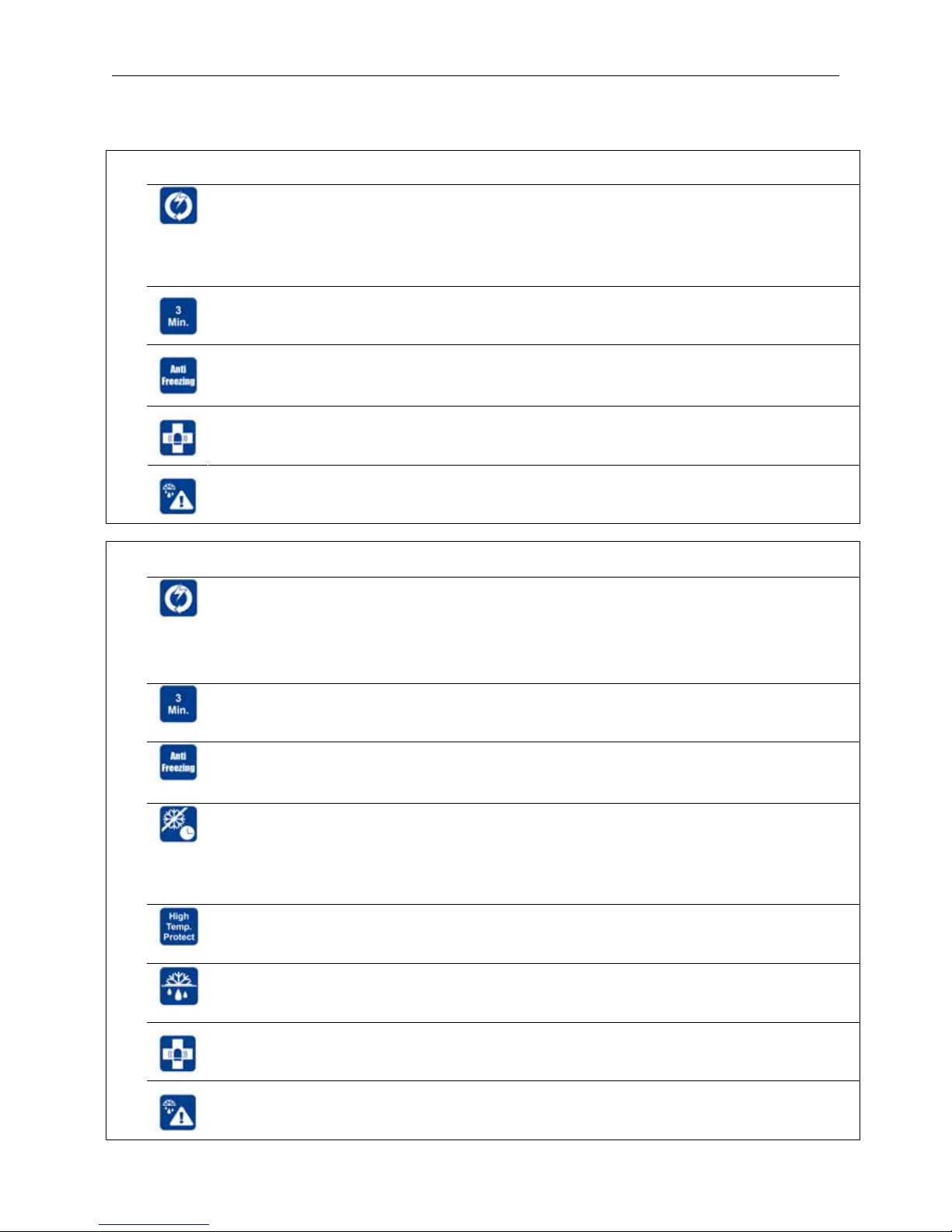
2.1 Safety protections for Cool Only System
Auto Restart Feature with backup memory.
When the power failure is happened during the air conditioner operation, the microprocessor
of printed circuit board will memorize the operation setting. After the power is recovered, the
air conditioner operates automatically ( without remote control after elapse of compressor
time delay ), according to the previous operation settings.
3 (Three) minutes time delay between compressor turning off and turning on for compressor
protection against cycling.
Anti-freezing protection of indoor coil when the system is operating in cool mode with
excessive dirt on the indoor coil and / or clogged air filters and when the air conditioner is
operating in cool mode at low ambient temperature.
Smart self-diagnostic function for malfunctions detection for fast easy service and
maintenance.
Smart refrigerant leak detection by sensitive sensors mounted on the indoor and outdoor
coils for fast easy service and maintenance.
2.2 Safety protections for Heat Pump System
Auto Restart Feature with backup memory.
When the power failure is happened during the air conditioner operation, the microprocessor
of printed circuit board will memorize the operation setting. After the power is recovered, the
air conditioner operates automatically ( without remote control after elapse of compressor
time delay ), according to the previous operation settings.
3 (Three) minutes time delay between compressor turning off and turning on for compressor
protection against cycling.
Anti-freezing protection of indoor coil when the system is operating in cool mode with
excessive dirt on the indoor coil and / or clogged air filters and when the air conditioner is
operating in cool mode at low ambient temperature.
Cold draft protection when the system is operating in heat mode.
When starting heat mode, the fan speed is regulated automatically from the lowest grade to
the preset level, according to the temperature rise of indoor coil. This function can prevent
cold air blowing out at the beginning of heat modem which avoids the discomfort to the
user.
High temperature protection of indoor coil when the air conditioner is operating in heat
mode.
Defrost protection of outdoor coil when the air conditioner is operating in heat mode
at very low ambient temperature.
Smart self-diagnostic function for malfunctions detection for fast easy service and
maintenance.
Smart refrigerant leak detection by sensitive sensors mounted on the indoor and outdoor
coils for fast easy service and maintenance.
Page 6
( 3 )
3. TIPS OF ENERGY SAVING AND OPTIMUM COMFORT
In Summer
• Keep room temperature to comfort levels.
• Don’t remain in direct contact
with cold air for a long period.
This is harmful to health.
• Don’t wait until it is too hot.
Turn the air conditioner for cooling before that.
• Don’t exaggerate on the temperature intensity, too cold.
Extreme temperatures are harmful to your health and
waste energy.
COOL mode HEAT mode
In Winter
• Keep room temperature to comfort levels.
• Don’t remain in direct contact
with warm air for a long period.
This is harmful to health.
• Don’t wait until it is too cold.
Turn the air conditioner for heating before that.
• Don’t exaggerate on the temperature intensity, too hot.
Extreme temperatures are harmful to your health and
waste energy.
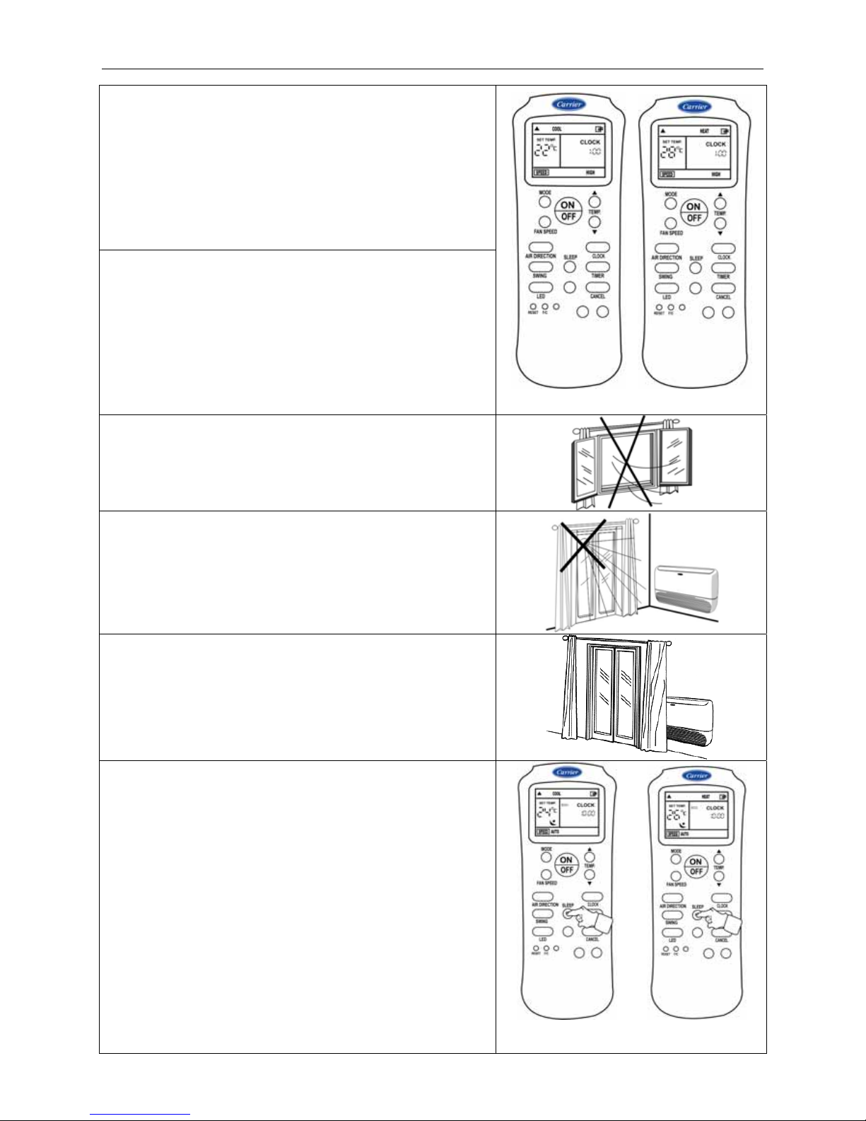
Keep doors, windows and any other openings closed to
prevent the conditioned air from escaping and to prevent
un conditioned air from entering the space to be air
conditioned.
When in cooling, avoid direct sun in the room to be air-
conditioned, if possible shut curtains or shades.
Keep doors, furniture or any other obstructions away from
blocking return air and / or supply air of the indoor unit to
assure maximum efficiency and adequate air circulation.
Use SLEEP function during sleep for energy
saving, comfortable and healthy sleep during cool
mode or heat mode.
COOL mode HEAT mode
With SLEEP function With SLEEP function
Page 7

( 4 )
TIPS OF ENERGY SAVING AND OPTIMUM COMFORT (Cont.)
Ensure a uniform air circulation in the
room to be air conditioned
Clean periodically air filter of indoor unit
every two weeks to assure adequate air
circulation and maximum cooling or
heating efficiency.
Periodic service and maintenance of the
air conditioner or upon customer request
through carrier or carrier authorized
dealer service center.
Air Filter
Return grille
Page 8
( 5 )
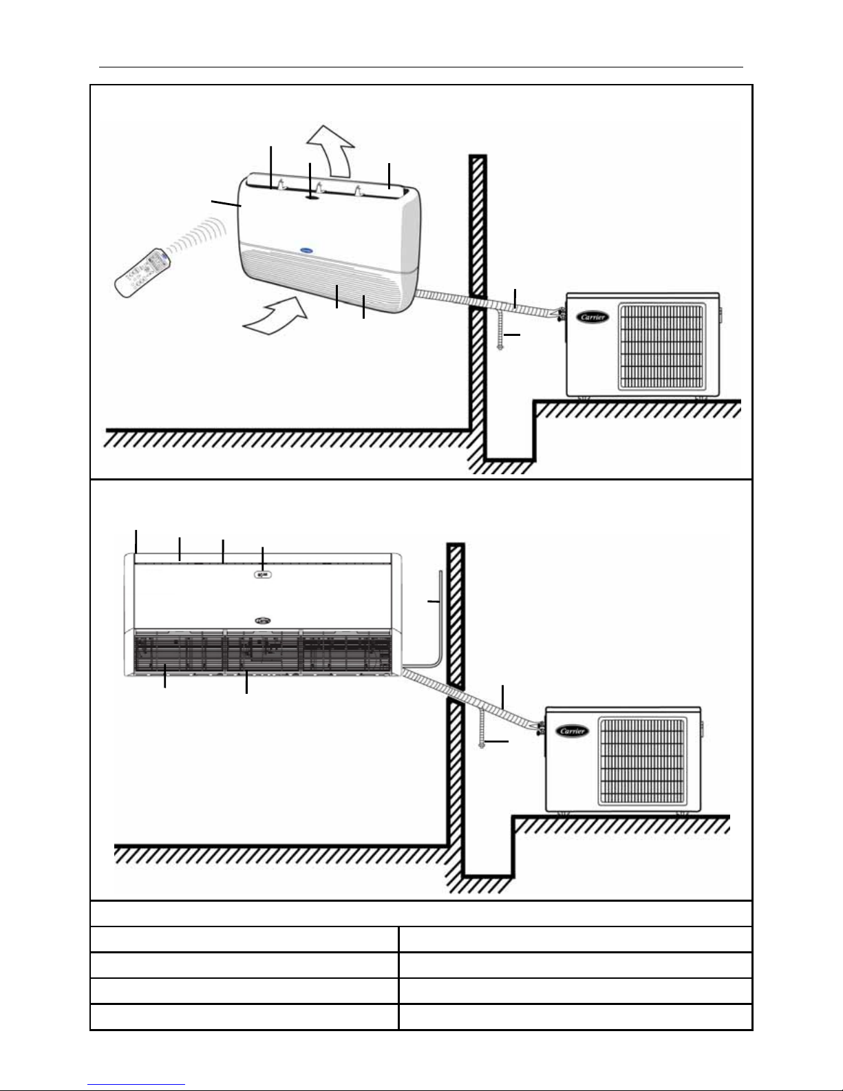
4. SPLIT SYSTEM DESCRIPTION
Sizes 18 - 24
Sizes 30 - 36
1: Remote control signal receiver.
2: Operating status leds. 6: Supply air outlet.
3: Supply air flap. 7: Characteristics nameplate.
4: Air return grille. 8: Refrigerant piping lines and electrical cables.
5: Air filter ( behind return grille ). 9: Condensate drain line.
Indoor Unit
Outdoor Unit
4
8
7
2
6
5
1
9
3
4
5
6
3
1
Outdoor Unit
Indoor Unit
7
8
9
10
Page 9

( 6 )
5. CONSIDERATIONS FOR REMOTE CONTROL
5-1 HOW TO INSERT BATTERIES :
(a) Remove the cover of battery
compartment at the back of the
remote control by pressing the
tab toward outside, in the direction
of the arrow.
(c) Press the button (at the front of remote
control) with an object not sharp to operate
the remote control.
(b) Mount two batteries size AAA 1.5 Volt supplied
with the remote control. Then close the cover
of the battery component.
Note:
During mounting of batteries
check battery symbols (+, -)
indicated in batteries
compartment.
NOTES
1. The remote control uses two alkaline batteries (1.5 Volts) .
2. Do not use old batteries or batteries of different types, as this may cause the remote control to malfunction.
3. If you do not use the remote control for more than a few weeks, please remove the batteries.
Other wise battery leakage may damage the remote control.
4. The average battery life during normal use is approximately half a year.
5. Replace the batteries when there is no receiving beep coming from the indoor unit or transmission
indicator on the remote control fails to light.
6. Batteries should only be replaced after turning OFF the air conditioner.
5-2 INSTRUCTIONS OF USING WIRELESS REMOTE CONTROL
1- The remote control must be directed toward the receiver of indoor unit when pressing the buttons
of the desired functions. An acoustical acknowledgement sound (beep) will indicate that signal has
been received.
2- Avoid direct sunlight on the receiver of indoor unit, which may interfere with good signal reception
and the air conditioner may not work properly. Draw the curtains to avoid direct sunlight.
3- Avoid obstacles obstructions such as curtains, doors or other materials between the remote control
and the receiver of indoor unit to avoid blocking the signals from the remote control to the indoor unit.
4- The maximum operating distance for the remote control is approximately 8 meters.
5- Keep the remote control away from water. Do not let the remote control fall down.
6- Never use objects with sharp point to press the button on the remote control.
7- Prevent any liquid from falling into the remote control.
8- If other electric applications react to the remote control, move these applications.
5m maximum
Page 10
( 7 )
6. DESCRIPTION OF LEDS DISPLAY AND EMERGENCY BUTTON
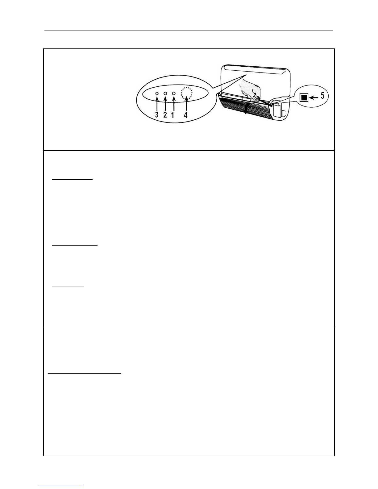
INDOOR UNITS 18 - 24
Indoor unit LED’s
• GREEN LED (1) shows the following conditions:
- Fault codes (diagnostic);
- During normal operation, the LED is lit.
Once a failure occurs, the LED flashes at intervals of 0.5 seconds. The fault code is deduced from the
number of times the LED flashes. Between one flash cycle and the next a pause of 5 seconds elapses.
If the timer mode is active and the unit is immediately restarted after a stop, this LED flashes until a
new signal is sent to the indoor unit.
• YELLOW LED (2) shows the operation in timer mode.
During this operation in this operating mode, the LED is lit.
If the time mode is active and the unit is immediately restarted after a stop, this LED flashes until a new
signal is sent to the indoor unit.
• RED LED (3) gives the following information:
- During normal operation, the LED is OFF;
- During defrost the LED is lit;
- During the test for wired connection, the LED
flashes at 1- second intervals.
Button (5) : “EMERGENCY”
Can be used when the remote control is lost or inoperative.
Use a screwdriver to press the push-button.
Emergency operation:
When the unit is in the OFF mode and the emergency is pressed for 5 seconds, the system will operate
as follows:
- Automatic mode.
- Temperature preset to 22ºC.
- Automatic fan speed.
- Louvers set automatically according to operating mode.
- Timer Functions are inactive.
When a signal is received by the remote control, system operates accordingly.
1 : Green Led
2 : Yellow Led
3 : Red Led
4 : Remote control
signal receiver
5 : “Emergency” button
Page 11
( 8 )
DESCRIPTION OF LEDS DISPLAY AND EMERGENCY BUTTON (Cont.)
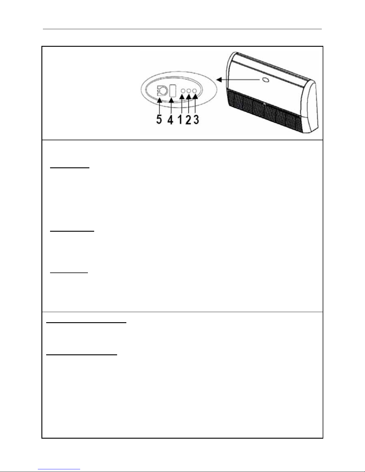
INDOOR UNITS 30 - 36
Indoor unit leds
• GREEN LED (1) shows the following conditions :
- Fault codes (diagnostic);
- During normal operation, the LED is lit.
Once a failure occurs, the LED flashes at intervals of 0.5 seconds. The fault code is deduced from the
number of times the LED flashes. Between one flash cycle and the next a pause of 5 seconds elapses.
If the timer mode is active and the unit is immediately restarted after a stop, this LED flashes until a
new signal is sent to the indoor unit.
• YELLOW LED (2) shows the operation in timer mode.
During this operation in this operating mode, the LED is lit .
If the time mode is active and the unit is immediately restarted after a stop, this LED flashes until a new
signal is sent to the indoor unit.
• RED LED (3) gives the following information:
- During normal operation, the LED is OFF;
- During defrost the LED is lit;
- During the test for wired connection, the LED
flashes at 1- second intervals.
EMEGENCY OPERATION (5)
Can be used when the remote control is lost or inoperative.
Use a screwdriver to press the push-button.
Emergency operation:
When the unit is in the OFF mode and the emergency is pressed for 5 seconds, the system will operate
as follows:
- Automatic mode.
- Temperature preset to 22ºC.
- Automatic fan speed.
- Louvers set automatically according to operating mode.
- Timer Functions are inactive.
When a signal is received by the remote control, system operates accordingly.
1 : Green Led
2 : Yellow Led
3 : Red Led
4 : Remote control
signal receiver
5 : “Emergency” button
Page 12
( 9 )
7. USE OF REMOTE CONTROL
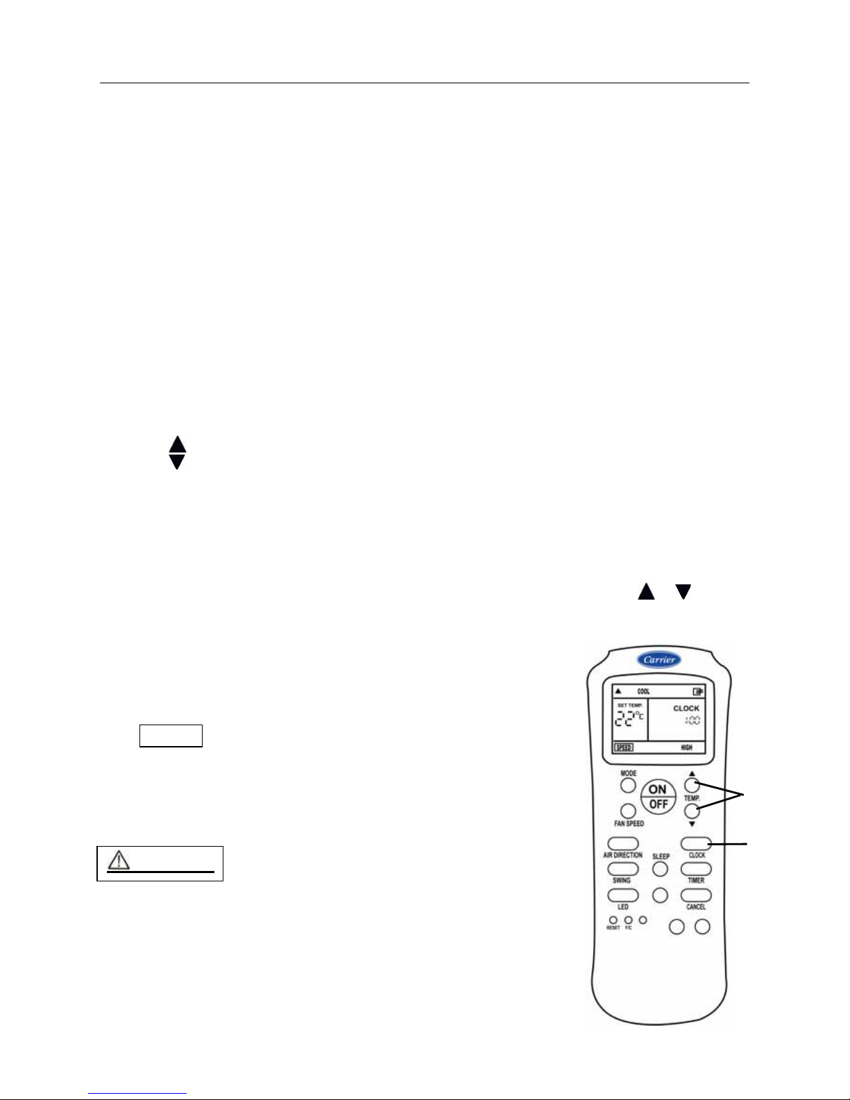
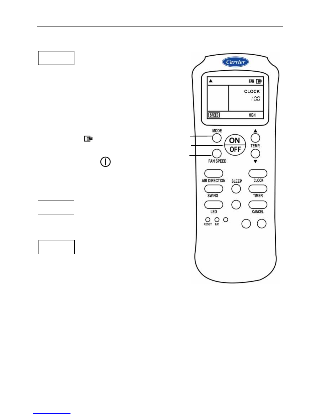
CLOCK ADJUSTING FUNCTION
Initial Setting or the Clock
When batteries are inserted in the remote control, the clock panel will display ‘’12:00’’
and being to flash.
Setting the clock
Before you start operating the air conditioner, set the clock of the remote control
using the procedures given in this section.
The clock display on the remote controller will show the time regardless of whether
the air conditioner is in use or not.
1.
With the remote control ON or OFF,
Press
CLOCK for about 3 seconds, the clock time display will start to flash.
2.
TEMP. button
• Press this button to set time.
Forward
Backward
• Each time you press the button, the time moves forward or backward by one minute
depending on which side you press.
The time alters as quickly as you press the button.
• Keep pressing the button without releasing, the time moves forward or backward by
10 minutes depending on which side you press.
3.
CLOCK button
When the right time is achieved, press the CLOCK button or release the
or
and wait for 3 seconds, the clock time stops flashing and the clock starts
4.
Readjusting the Clock
Press the CLOCK button on the remote controller
for about 3 seconds, the time of the clock display
will start to flash. To set the new time, follow 1 and 2
of "Initial Setting of the Clock".
NOTES
* The clock time must be set before operating TIME functions.
* The clock time cannot be adjusted during TIME operation.
* Clock accuracy is within 15 seconds per day.
CAUTIONS
Static electricity or other factors (voltage transients )
can cause remote controller clock initialise.
If your remote controller is initialised
readjust the clock before you start operation.
2
1
3
Page 13

( 10 )
USE OF REMOTE CONTROL (Cont.)
COOL MODE
START
1. Press MODE button to select COOL mode
on the remote control display.
2. Press TEMP buttons or to select the
set temperature on the remote control display.
Set desired temp. between 17°C and 30°C.
3. Press FAN SPEED button to select
the desired fan speed on the remote
control display.
4. Press ON/OFF button to start
the air conditioner.
ON symbol appears on the
remote control display.
OPERATION led will illuminate
on the display panel of indoor unit.
COOL mode starts after approximately 3 minutes
STOP
If you want to stop the air conditioner,
Press ON/OFF button again.
NOTES
• If the room temperature is higher than
the selected temperature, the system will start COOL mode.
• If the room temperature is equal to or less than
the selected temperature, the system will stop COOL mode.
• If you use AUTO fan speed with COOL mode, the fan speed
changes automatically to low or medium or high speed
based on the temperature difference between setting
temperature and room temperature.
4
2
2
1
3
Page 14

( 11 )
USE OF REMOTE CONTROL (Cont.)
HEAT MODE
START
1. Press MODE button to select HEAT mode
on the remote control display.
2. Press TEMP buttons or to select the set
temperature on the remote control display.
Set desired temp. between 17°C and 30°C.
3. Press FAN SPEED button to select
the desired fan speed appears
on the remote control display.
4. Press ON/OFF button to start
the air conditioner.
ON symbol appears on the
remote control display.
OPERATION led will illuminate
on the display panel of indoor unit.
HEAT mode starts after approximately 3 minutes
STOP
If you want to stop the air conditioner,
Press ON/OFF button again.
NOTES
• If the room temperature is lower than
the selected temperature, the system will start HEAT mode.
• If the room temperature is equal to or higher than
the selected temperature, the system will stop HEAT mode.
• If you use AUTO fan speed with HEAT mode, the fan speed
changes automatically to low or medium or high speed
based on the temperature difference between setting
temperature and room temperature.
4
2
2
1
3
Page 15

( 12 )
USE OF REMOTE CONTROL (Cont.)
AUTO MODE
START
1. Press MODE button to select AUTO mode
on the remote control display.
2. Press TEMP buttons or to select the
set temperature on the remote control display.
Set desired temp. between 17°C to 30°C .
3. Press FAN SPEED button to select
the desired fan speed appears
on the remote control display.
4. Press ON/OFF button to start
the air conditioner.
ON symbol appears on the
remote control display.
OPERATION led will illuminate
on the display panel of indoor unit.
AUTO mode starts after approximately 3 minutes
STOP
If you want to stop the air conditioner,
Press ON/OFF button again.
NOTES
1. For Heat Pump System
When Auto mode is activated, the air conditioner changes the operation mode automatically to cool
or heat or fan only mode and also changes fan speed to auto speed by sensing the temperature
difference between room temperature and set temperature.
2. For Cool Only System
When Auto mode is activated, the air conditioner changes the operation mode automatically to cool
or fan only mode and also changes fan speed to auto speed by sensing the temperature difference
between room temperature and set temperature.
3. In the Auto mode, you cannot switch the fan speed. It has already been automatically controlled.
4. If the Auto mode is not comfortable for you, the desired mode can be selected manually.
5. If the Eco function is activated when the unit is operating in Auto mode, the fan speed will change
into Low speed mode immediately.
4
2
2
1
3
Page 16
( 13 )
USE OF REMOTE CONTROL (Cont.)
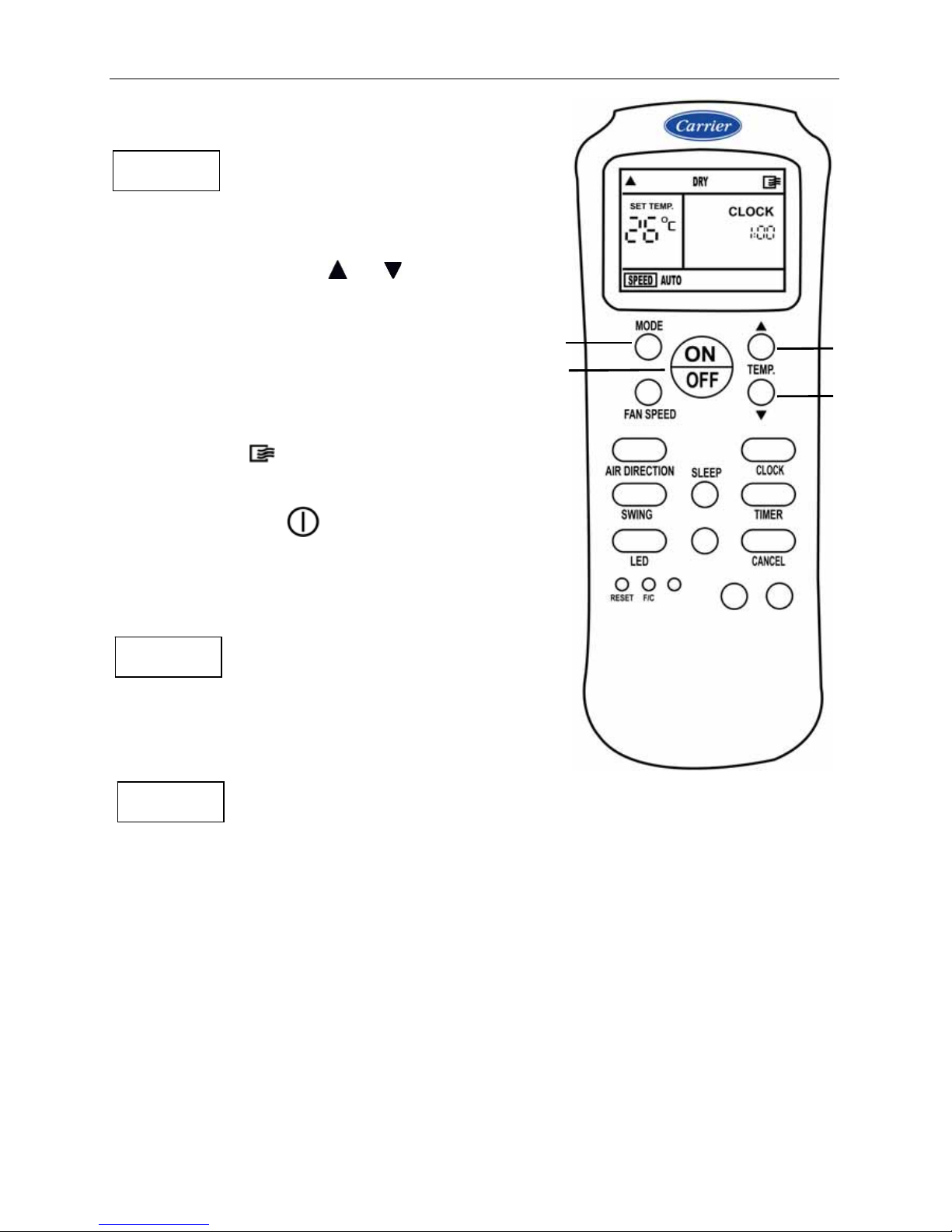
DRY MODE
START
1. Press MODE button to select DRY mode
on the remote control display.
2. Press TEMP buttons or , to select the
set temperature the remote control display.
Set desired temp. between 17°C to 30°C .
3. Press ON/OFF button to start
the air conditioner.
ON symbol
appears on the
remote control display.
OPERATION led
will illuminate
on the display panel of indoor unit.
DRY mode starts after approximately 3 minutes
STOP
If you want to stop the air conditioner,
Press ON/OFF button again.
NOTES
• In DRY mode, you can not switch the indoor indoor fan speed.
The indoor fan speed will be automatically selected AUTO.
• The DRY mode will automatically select the drying operation based on the
difference between the set temperature and the actual room temperature.
• The temperature is regulated while dehumidifying by repeating turning on
and off of the cooling operation or fan only.
3
2
2
1
Page 17
( 14 )
USE OF REMOTE CONTROL (Cont.)
FAN ONLY MODE
START
1. Press MODE button to select FAN mode
on the remote control display.
2. Press FAN SPEED button to select
the desired fan speed on the remote
control display.
3. Press ON/OFF button to start
the air conditioner.
ON symbol appears
on the remote control display.
OPERATION led will illuminate
on the display panel of indoor unit.
FAN ONLY mode starts immediately.
STOP
If you want to stop the air conditioner,
Press ON/OFF button again.
NOTES
• In FAN mode, the unit will start immediately.
• FAN mode does not control temperature.
The setting temperature is not displayed on
the remote control display.
3
1
2
Page 18

( 15 )
USE OF REMOTE CONTROL (Cont.)
SWING FUNCTION
Press button SWING repeatedly to choose the following flap :
The louver will continuously swing up and down.
“Swing” always assures optimal even air distribution in the room.
• In Cool or Dry or Fan mode, the louver will swing in cooling range.
• In Heat mode, the louver will swing in heating range.
Note:
If you want to cancel swing function
Press button
SWING at the desired flap position
AIR DIRECTION FUNCTION
The air conditioner automatically adjusts the vertical supply air
direction in accordance with the operating mode.
To set the vertical supply air direction (Up- Down)
• Perform this function while the unit is in operation.
• Keep pressing the AIR DIRECTION button on the remote
control to move the louver to the desired.
• In subsequent operations, the vertical air flow is automatically
set in the direction to which you adjusted the louver
by pressing the AIR DIRECTION button.
Left and Right Control
If you want to adjust the direction of the discharge air to left or right,
adjust the vertical louver with the handle after opening the flap.
NOTES:
• Please do not fix the flap for a long time, as this position minimizes
air circulation resulting in uneven room temperature.
• Please avoid the discharge air being directed towards the occupants for a long period of time.
• Do not adjust the flap by the hand during SWING operation because it may damage the air swing
function.
COOL
HEAT
Swing Range
Page 19

( 16 )
USE OF REMOTE CONTROL (Cont.)
SLEEP Function
HEALTHY SLEEP TIMER FUNCTION
Sleep function is useful when you go to sleep.
When Sleep function is activated, the air conditioner automatically controls the selected temperature
and consequently controls the room temperature to avoid overcooling or overheating and to have
comfortable and healthy sleep.
SLEEP function with COOL Mode
If you want to operate SLEEP function with Cool mode to save energy
and maintain the most comfortable temperature during COOL mode,
apply the following steps :
Start:
Press SLEEP button to activate SLEEP function
Then the logo of function show on display of remote control.
• The fan speed will automatically change to low speed.
• The set temperature will be automatically increased by 1°C
after 1 hour after COOL mode is selected.
• Then the set temperature will be automatically increased by
another 1°C after additional 1 hour.
• This new temperature will be maintained.
Stop:
If you want to cancel SLEEP function, press any other button.
SLEEP function with HEAT Mode
If you want to operate SLEEP function with Cool mode to save energy
and maintain the most comfortable temperature during HEAT mode,
apply the following steps :
Start:
Press SLEEP button to activate SLEEP function
Then the logo of
function show on display of remote control.
• The fan speed will automatically change to low speed.
• The set temperature will be automatically decreased by 1°C
after 1 hour after HEAT mode is selected.
• Then the set temperature will be automatically decreased by
another 1°C after additional 1 hour.
• This new temperature will be maintained.
Stop:
If you want to cancel SLEEP function, press any other button.
NOTE
SLEEP function is only available with COOL, HEAT
and AUTO mode.
SLEEP function with COOL mode
SLEEP function with HEAT mode
Page 20

( 17 )
USE OF REMOTE CONTROL (Cont.)
TIMER ON FUNCTION ( Off → Start Operation )
TIMER ON function is useful when you want to start automatically the air conditioner at a desired setting time
when you wake up in the morning or when you return home.
Example:
To automatically start the air conditioner at 6:00 in the morning
Proceed with following steps :
(1) Press TIMER button until the remote control display shows.
TIMER ON indicator and the last setting time which is flashing.
Now it is ready to reset the setting time of TIMER ON function.
(2) To set the desired time, Press TEMP. button (Forward)
or (Backward) unit the time 6:00 is displayed.
Each time you press there the button, the time moves forward
or backward by 10 minutes depending on which one you
press. The time alters as quickly as you press the button.
(3)
After setting the time for TIMER ON function,
the TIMER led
will illuminate
on the display panel of the indoor unit.
TO CANCEL TIMER ON FUNCTION
Press CANCEL button if you want to cancel
TIMER ON setting.
TO CHANGE TIMER ON SETTING
Perform steps 1, 2 and 3 to change TIMER ON setting.
CAUTION
When you select the timer operation, the remote control
automatically transmits the timer signal to the indoor
unit at the specified time. Therefore, keep the remote
control in a location from which it can transmit the
signal to the indoor unit properly.
The effective operation time set by remote control is
limited in 24 hours.
Start
Off
Set
Page 21

( 18 )
USE OF REMOTE CONTROL (Cont.)
TIMER OFF FUNCTION ( On → Stop Operation )
TIMER OFF function is useful when you want to stop automatically the air conditioner at a desired setting time
after you go to bed.
Example :
To automatically stop the air conditioner at 23:00 in the evening
proceed with the following steps :
(1) Press TIMER button until the remote control display shows.
TIMER OFF indicator and the least setting time which is flashing
Now it is ready to reset the setting time of TIMER OFF function
(2) To set the desired time, Press TEMP. button (Forward)
(Backward) unit the time 23:00 is displayed.
• Each time you press the button the time moves forward or
backward by 10 minutes depending on which one you
push. The time alters as quickly as you press the button.
(3) After setting the time for TIMER ON function,
the TIMER led
will illuminate
on the display panel of the indoor unit is illuminated.
TO CANCEL TIMER ON FUNCTION
If you want to cancel TIMER OFF setting,
Press CANCEL button.
TO CHANGE TIMER ON SETTING
Perform steps 1, 2 and 3 to change TIMER OFF setting.
CAUTION
When you select the timer operation, the remote control
automatically transmits the timer signal to the indoor
unit at the specified time. Therefore, keep the remote
control in a location from which it can transmit the
signal to the indoor unit properly.
The effective operation time set by remote control is
limited in 24 hours.
Stop
On
Set
Page 22

( 19 )
USE OF REMOTE CONTROL (Cont.)
COMBINED TIMER ON → TIMER OFF FUNCTION
( Off → Start Operation → Stop Operation )
You can use this setting to automatically start operation of the air conditioner before you wake up and
automatically stop it after you leave the home.
Example:
If you want to start operation of the air conditioner at 6:00 AM
the next morning, and stop at 8:00 AM proceed as follows:
1. Press TIMER button until TIMER ON indicator is displayed and setting time is flashing.
2. Use TEMP/TIME button to display "6:00" beside the TIMER ON indicator.
Wait 3 seconds, the TIMER ON time will be registered.
3. Press TIMER button again until TIMER OFF indicator is displayed and setting time is flashing.
4. Use TEMP/TIME button to display "8:00" on the TIMER OFF indicator.
5. Wait 3 seconds until the setting time stops flashing and this function is activated.
NOTES
If you want to cancel ON or OFF timer setting, press CANCEL button.
The timer function (ON or OFF ) which in time is closest to the actual time will be activated first.
If the same time is set for both ON and OFF timers, no timer operation is performed.
Also, the air conditioner may stop operating.
6:00
Set
Start
Stop
Off
8:00
Page 23
( 20 )
USE OF REMOTE CONTROL (Cont.)
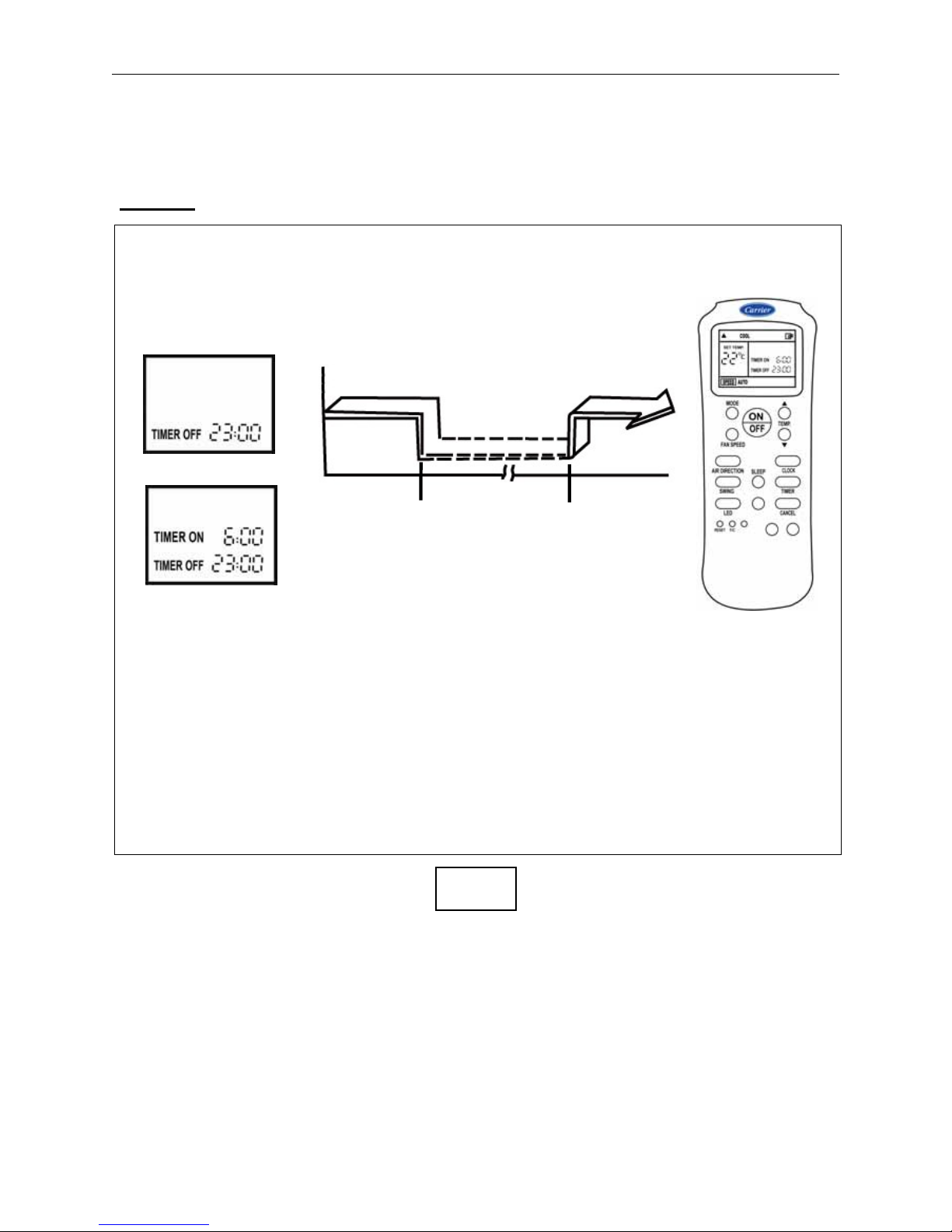
COMBINED TIMER OFF → TIMER ON FUNCTION
( On → Stop Operation → Start Operation )
You can use this setting to automatically stop the air conditioner after you go to sleep and start it
automatically again in the morning when you wake up or you return home.
Example:
Now it is 20: o’clock in the evening
If you want to automatically stop operation at 23:00 PM and automatically start
again at 6:00 AM in the next morning with the same operating mode, proceed as
follows:
To start the air conditioner at 6:00 the next morning, and stop it at 8:00.
1. Press TIMER button, until TIMER OFF indicator is displayed and the setting time is flashing.
2. Use the TEMP/TIME button to display "23:00" beside the TIMER OFF indicator of the remote control.
Wait 3 seconds, the TIMER OFF time will be registered.
3. Press TIMER button again until TIMER ON indicator is displayed and setting time is flashing.
4. Use TEMP/TIME button to display "6:00" beside the TIMER ON indicator.
5. Wait 3 seconds until the setting time stops flashing and this function is activated.
NOTES
If you want to cancel ON or OFF timer setting, press CANCEL button.
The timer function (ON or OFF ) which in time is closest to the actual time will be activated first.
If the same time is set for both ON and OFF timers, no timer operation is performed.
Also, the air conditioner may stop operating.
23:00
Set
Start
Stop
On
6:00
Page 24

( 21 )
USE OF REMOTE CONTROL (Cont.)
RESET Function F/C Function
When you press the recessed RESET button, all current
settings are cancelled and return to original factory settings.
• The clock time “12:00” will flash
• The mode displays “AUTO”
• The fan speed displays “AUTO”
• The temperature displays “24”
Note : You will need to reprogram the clock setting after
Pressing RESET button
LOCK Function
1. Use LOCK function when you want to prevent settings
from being changed accidentally.
2. When you press TEMP. ▲and ▼ buttons as the same
time, all current settings are locked in and the remote
control does not accept any operation except that of the
LOCK.
3. A LOCK symbol will appear on the bottom right
hand sides of the remote control display when the LOCK
function is activated.
4. If you want to cancel LOCK function,
Press again TEMP. ▲and ▼ buttons as the same time.
Used to select / display temperature
settings in either “ Celsius ” or
Fahrenheit. Press this button to select
either the Celsius or Fahrenheit scale.
Page 25

( 22 )
8. AIR FILTERS CLEANING
WARNING:
It is necessary to stop the air conditioner and disconnect the power supply before
cleaning air filters.
- The air filters supplied with the unit are high-efficiency washable and recyclable filters.
- To establish, how frequently these should be cleaned, the operating conditions must
be taken in to account.
- REMOVAL OF AIR FILTERS FOR CLEANING:
Indoor Units 18 - 24 Indoor Units 30 - 36
To remove air filters
1. Open the return grille without
removing the two screws and the
central clamp from their position.
To remove air filters
1. Open the return grille without
removing the two screws and the
central clamp from their position
2. Remove filters
2. Remove air filters for cleaning.
- CLEANING OF STANDARD AIR FILTERS:
3. First clean the filter with a vacuum
cleaner every month.
And Rinse filter under running water,
and dry it.
3. First clean the filter with a vacuum
cleaner every month.
And Rinse filter under running water,
and dry it.
4. After cleaning, put the filters back in
the correct positions.
4. After cleaning, put the filters back in
the correct positions.
Notes:
(1) After cleaning, put the filters back in the correct positions.
(2) Before operating the air conditioner, check that air filters are in their places inside unit.
Page 26

( 23 )
9. INDOOR UNIT CLEANING
Turn the unit off and switch the mains supply off.
Use only a clean, damp and soapy cloth.
Do not pour any liquids on the unit.
Do not use flammable liquid, solvents or
abrasive powders: these can damage the
casing.
Avoid any contact with sources of heat, as
hot air can damage the unit casing.
Clean the infrared control using a damp
cloth.
9-2 INDOOR COIL CLEANING
It is recommended to clean the coil at least at the beginning of each cooling season or when necessary;
turn the unit off first.
• Use a vacuum cleaner or a long-bristle brush to avoid damage to the coil fins.
• Watch the fin edges to avoid injury.
• Damage to the fins may cause reduced coil efficiency resulting in increased running costs. Use
of flames, liquid or aerosol solvents must be avoided. Use of these substances will cause serious
damage to the panels and electric parts.
Page 27

( 24 )
10. PERIODICAL CHECKS
WARNING:
It is necessary to stop the air conditioner and disconnect the power supply before
performing service and maintenance operations.
For a good operation of the air conditioner it is recommended to carry out periodic service and
maintenance of the air conditioner or upon customer request through Carrier or Carrier authorized dealer.
Recommended service and maintenance works and intervals may vary depending on the installation
environment, e.g. dusty zones, etc. see below table :
Indoor Unit
Every Month Every Year
Clean air filters
(3)
●
(1)
Clean drain pipe
(2)
●
Change remote control batteries
(4)
●
Outdoor Unit
Every Month Every Year
Clean outdoor coil
(2)
●
Blow air over electric parts
(2)
●
Check electric connection tightening
(2)
●
Clean fan wheel
(2)
●
Check fan tightening
(2)
●
Clean drain pan
(2)
●
NOTES
(1) Increase frequency in dusty zones.
(2) Service and maintenance works to be carried out by qualified service personnel.
(3) Cleaning air filters can be done by customer every month.
(4) Changing batteries of remote control can be done by customer every year.
11. CONSIDERATIONS BEFORE A LONG SHUTDOWN
PERIOD OF AIR CONDITIONER
Keep the indoor unit in operation for half
a day in the ventilation (fan only) mode
in order to dry all internal parts.
Switch electric mains supply off.
Take batteries out of the remote control.
Clean indoor and outdoor units.
Clean the air filters and reposition them
in the unit.
12h
Page 28

( 25 )
12. OPERATION TIPS
The following events may occur during normal operation of the air conditioner:
1. A slight white mist (water vapor)coming out from the indoor unit during cooling
A white mist may generate due to a large temperature difference between air inlet and air outlet on
COOL mode in an indoor environment that has a high relative humidity.
The cool air from the indoor unit is coming into contact with the room air.
A white mist may generate due to moisture generated from defrosting process when the air
conditioner restarts in HEAT mode operation after defrosting.
2. Low noise of the air conditioner
You may hear a low hissing sound when the air conditioner is running or has just stopped
running.
This sound is the sound of the refrigerant beginning to circulate or an adjustment of the
refrigerant pressures after stopping.
You can also hear a low short "squeak" when the indoor unit is in operation or when it has
stopped.
These are generally due to the temperature changes on the plastic parts ( expansion or
contraction ).
A noise may be heard due to louver restoring to its original position when power is first turned on.
3. Dust is blown out from the indoor unit.
This is a normal condition when the air conditioner has not been used for a long time or during first
use of the unit.
4. Unpleasant smells coming out from the indoor unit.
Unpleasant smells can be caused by substances accumulated in the air filters of indoor unit.
In this case, you must switch the system off and air filters must be cleaned.
Restart the unit in ventilation ( fan only ) mode and open windows to change the room air,
5. The air conditioner turns to FAN only mode from COOL or HEAT.
When indoor temperature reaches the temperature setting on air conditioner compressor will stop
automatically the ,and the ,air conditioner turns to FAN only mode.
The compressor will start again when the indoor temperature rises on COOL mode or falls on HEAT
mode (only for heat pump system) to the set point.
6. Dripping water may generate on the surface of the indoor unit
(when cooling in a high relatively humidity higher than 80%).
Adjust the horizontal louver to the maximum air outlet position and select HIGH fan speed.
7. Heating mode For.
The air conditioner draws in heat from the outdoor unit and releases it via the indoor unit during
heating operation. When the outdoor temperature falls, heat drawn in by the air conditioner
decreases accordingly.
At the same time, heat loading of the air conditioner increases due to larger difference between
indoor and outdoor temperature. If a comfortable temperature can't be achieved by the air
conditioner, we suggest you use a supplementary heating device.
8. Mist (water vapor) coming out from the outdoor unit during heating
It is normal in heat pump operation when defrost is automatically activated during heating operation
at very low ambient.
9. Lightning or a car wireless telephone operating nearby may cause the unit
to malfunction.
Disconnect the unit with power and then re-connect the unit with power again.
Push the ON/OFF button on the remote controller to restart operation.
Page 29

( 26 )
13. TROUBLE SHOOTING
TROUBLE REASON ACTION
After batteries have been placed
into the remote control, the
display is not lit.
Batteries are exhausted or have
the wrong polarity.
Replace batteries or check
polarity.
When pressing the recessed
clock adjustment button, hour
figures on display do not flash.
Recessed button has not been
pressed correctly.
Press with a round point, avoid
exerting strong pressure
When pressing any button, all
symbols appear on display.
Recessed button for time setting
is blocked due to excessive
pressure during use.
Check and repair.
Remote control has been
irreversibly damaged.
Replace with a new one.
When pressing start button, unit
does not acknowledge signal
with a beep.
OR
When pressing stop button, unit
does not acknowledge signal
with a beep.
OR
When pressing any function
button, the remote control shows
the function requested on the
display, but unit does not
acknowledge signal receipt with
a beep and does not carry out
the function.
Main switch is OFF. Switch it to ON position.
Remote control batteries are
exhausted.
Replace batteries.
Remote control has not been
pointed correctly to the receiver
of indoor unit.
Turn remote control OFF and
repeat the operation in the
correct direction.
There are obstacles (curtains,
walls, etc.) between the remote
control and the indoor unit
Repeat the operation after having
removed the obstacles.
Receiver on the indoor unit or the
remote control is under intense
sun radiation.
Avoid direct sun on the unit, shut
curtains or shades.
Signal transmission is
obstructed by severe
interference from an
electromagnetic field.
Avoid sending signals when
computers or household
appliances (Food processors,
coffee makers, etc.) are operating
close by cellular or cordless
telephones may also interfere
with the control.
Page 30
( 27 )
TROUBLE SHOOTING (Cont.)
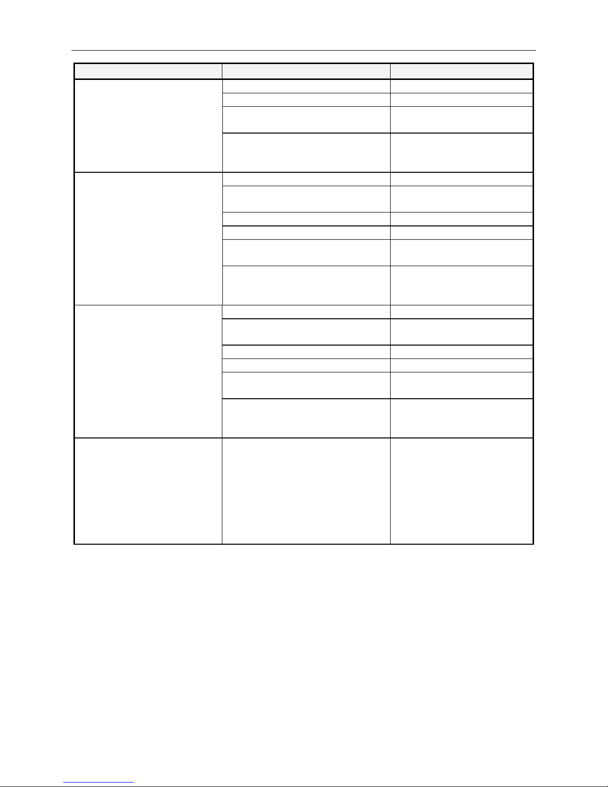
TROUBLE REASON ACTION
Air conditioner will not start. Main supply switch is OFF Switch to ON
Fuses or main switch are blown Replace fuses
Protection against frequent
compressor cycling is ON
Wait for 3 minutes.
Selected temperature is higher than
the room temperature in the cooling
mode (or lower in the heating mode).
Correct selected temperature.
Air conditioner is not supplying
enough cooling.
Air flow cannot circulate freely Remove obstructions.
Dirty filters reduce air quantity
circulating.
Clean air filters
Doors and/or windows are open. Close doors and windows
Fan speed has been set to “Low” Set fan speed at high speed.
Air flow direction is not correct Adjust airflow direction as per
the mode chosen.
Selected temperature is higher than
the room temperature in the cooling
mode.
Correct selected temperature.
Air conditioner is not supplying
enough heating.
Air flow cannot circulate freely Remove obstructions.
Dirty filters reduce air quantity
circulating.
Clean air filters
Doors and/or windows are open. Close doors and windows
Fan speed has been set to “Low” Set fan speed at high speed.
Air flow direction is not correct Adjust airflow direction as per
the mode chosen.
Selected temperature is Lower than
the room temperature in the heating
mode.
Correct selected temperature.
Green led on the display panel
of indoor unit is showing a
malfunction
System malfunction. Contact service
center after having made the
following checks:
• Air filters are clean.
• Air circulation is not obstructed.
• Outdoor unit coil is not
obstructed with a severe
reduction of air circulation.
Refer to the installation
manual for fault code reading
to be notified to service center.
Restart air conditioner after
having corrected the faults.
Page 31

Harmony
Floor / Under-Ceiling Split Systems
Wireless Remote Control
Display of Indoor Unit
OPERATION green led
TIMER function yellow led
Cold Draft or Defrost red led
Remote control signal receiver
Cold Draft or Defrost red led
TIMER function yellow led
OPERATION green led
Remote control signal receiver
Emergency switch
SPEED
LOW MED HIGHAUTO
SET TEMP.
TIMER ON
TIMER OFF
CLOCK
o
DRY
FAN
HEAT
COOL
AUTO
2
4
5
9
1
8
10
6
3
7
Signal transmission indicator
1
Operating mode indicator
2
Automatic (heat pump model only)
AUTO
Cooling and dehumidication
COOL
Dehumidication only
DRY
Heating (heat pump models only)
HEAT
Ventilation (fan only)
FAN
ON/OFF indicator
3
SET TEMP. indicator
4
Temperature unit of measurement
(ºC or ºF)
5
Current time
6
ON TIMER or OFF TIMER
7
FAN SPEED indicator
8
FAN SPEED indicator AUTO
AUTO
FAN SPEED indicator LOW
LOW
FAN SPEED indicator MED
MED
FAN SPEED indicator HIGH
HIGH
SLEEP function indicator
9
LOCK function indicator
10
Display of Remote Control
18K - 24K 30K - 36K
18K - 24K
30K - 36K
Page 32

Harmony
Floor / Under-Ceiling Split Systems
Wireless Remote Control
18K - 24K 30K - 36K
MODE selection button
1
Decrease temperature button
2
Increase temperature button
3
FAN SPEED selection button
4
ON/OFF button
5
SWING horizontal ap button
6
AIR DIRECTION horizontal ap button
7
SLEEP function button
8
CLOCK adjusting button
9
TIMER ON or TIMER OFF function button
10
CANCEL TIME function button
11
LED DISPLAY function button
12
RESET function button
13
F/C function button
14
DISPLAY
2
9
10
11
3
1
5
4
7
6
13
12
8
14
Control Buttons
 Loading...