

Carrier GZ024, GZ048, GZ060, GZ036, GZ072 Installation Instructions Manual
GZ Series
Geothermal System
Sizes 024, 036, 048, 060, 072
Installation Instructions
NOTE: Read the entire instruction manual before starting the installation.
TABLE OF CONTENTS
PAGE N O.
SAFETY CONSIDERATIONS 1.....................
INSTALLATION RECOMMENDATIONS 2...........
APPLICATION CONSIDERATIONS 3................
Geothermal Systems 3............................
Open Loop Well Water Systems 4...................
MATCHED SYSTEM 7.............................
REFRIGERANT LINES 7...........................
WATER PIPING 9..................................
Loop Pump Connections 9........................
Water Solenoid Valves 9..........................
Flow Regulator Valves 9..........................
Typical Open Loop Piping 10.......................
HRP Water Piping 11..............................
ELECTRONIC THERMOSTAT INSTALLATION 12.....
Field Connections 12..............................
ELECTRICAL 13...................................
FACTORY INSTALLED FEATURES 15................
Heat Recovery Package (HRP) 15....................
FIELD INSTALLED ACCESSORIES 15................
Liquid Line Solenoid (LLS) Accessory 15.............
Outdoor Air Temperature Sensor (OAT) 16.............
Compressor Start Accessories 16.....................
PRE START--UP CHECKLIST 17.....................
UNIT START--UP 17.................................
USER INTERFACE QUICK SET--UP 17................
UI SYSTEM INITIAL POWER UP AND CHECKOUT 18.
SYSTEM VERIFICATION 18.........................
UPM SEQUENCE OF OPERATION FLOW CHART 18...
SYSTEM FUNCTION & SEQUENCE OF OPERATION 20
Communication and Status Function Lights 20..........
Time Delays 20..................................
Compressor Operation 20..........................
Safety Devices and UPM Board 20...................
TIMER SPEEDUP/TEST MODE 22....................
AUXILIARY HEAT LOCKOUT 22....................
BLOWER PERFORMANCE DATA TABLE 23..........
WATER SIDE PRESSURE DROP (PSIG) TABLE 24......
OPERATING TEMP. AND PRESSURES TABLES 25.....
TROUBLESHOOTING 30
Fault Code Table 30...............................
Troubleshooting Units for Proper Switching
Between Low & High Stages 31.....................
Systems Communication Failure 31..................
MODEL PLUG 31...................................
SERVICE TOOL 32.................................
HRP TROUBLESHOOTING 32.......................
10K TEMPERATURE SENSOR RESISTANCE TABLE 33
MAINTENANCE 34.................................
............................
Information in these installation instructions pertains only to GZ
series units.
SAFETY CONSIDERATIONS
Improper installation, adjustment, alteration, service, maintenance,
or use can cause explosion, fire, electrical shock, or other
conditions which may cause death, personal injury, or property
damage. Consult a qualified installer, service agency, or your
distributor or branch for information or assistance. The qualified
installer or agency must use factory--authorized kits or accessories
when modifying this product. Refer to the individual instructions
packaged with the kits or accessories when installing.
Follow all safety codes. Wear safety glasses, protective clothing,
and work gloves. Use quenching cloth for brazing operations.
Have fire extinguisher available. Read these instructions
thoroughly and follow all warnings or cautions included in
literature and attached to the unit. Consult local building codes and
current editions of the National Electrical Code (NEC) NFPA 70.
In Canada, refer to current editions of the Canadian electrical code
CSA 22.1.
Recognize safety information. This is the safety--alert symbol
When you see this symbol on the unit and in instructions or
manuals, be alert to the potential for personal injury. Understand
these signal words; DANGER, WARNING, and CAUTION. These
words are used with the safety--alert symbol. DANGER identifies
the most serious hazards which will result in severe personal injury
or death. WARNING signifies hazards which could result in
personal injury or death. CAUTION is used to identify unsafe
practices which would result in minor personal injury or product
and property damage. NOTE is used to highlight suggestions
which will result in enhanced installation, reliability, or operation.
!
ELECTRICAL SHOCK HAZARD
Failure to follow this warning could result in personal injury
or death.
Before installing, modifying, or servicing system, main
electrical disconnect switch must be in the OFF position.
There may be more than 1 disconnect switch. Lock out and
tag switch with a suitable warning label.
UNIT OPERATION AND SAFETY HAZARD
Failure to follow this warning could result in personal injury
or equipment damage.
PuronR refrigerant systems operate at higher pressures than
standard R --22 systems. Do not use R--22 service equipment
or components on PuronR refrigerant equipment.
WARNING
!
WARNING
!
!

!
WARNING
EXPLOSION HAZARD
Failure to follow this warning could
result in death, serious personal injury,
and/or property damage.
Never use air or gases containing
oxygen for leak testing or operating
refrigerant compressors. Pressurized
mixtures of air or gases containing
oxygen can lead to an explosion.
!
CAUTION
CUT HAZARD
Failure to follow this caution may result in personal injury.
Sheet metal parts may have sharp edges or burrs. Use care and
wear appropriate protective clothing and gloves when
handling parts.
1
2
1. GZ Series Water--To Air Split System
2. Packet containing: Installation, Owner’s Manual, Warranty
Certificate and badges
Fig. 1 -- Standard Package
A14176
INSTALLATION RECOMMENDATIONS
The Water--to--Air Heat Pumps are designed to operate with
entering fluid temperature between 20_Fto90_F in the heating
mode and between 30_F to 120_F in the cooling mode.
NOTE:50_F minimum Entering Water Temperature (EWT) is
recommended for well water applications with sufficient water
flow to prevent freezing. Antifreeze solution is required for all
closed loop applications. Geothermal applications should have
sufficient antifreeze solution to protect against extreme conditions
and equipment failure. Frozen water coils are not covered under
warranty. Other equivalent methods of temperature control are
acceptable.
Check Equipment and Job Site
Moving and Storage
If the equipment is not needed for immediate installation upon its
arrival at the job site, it should be left in its shipping carton and
stored in a clean, dry area. Units must only be stored or moved in
the normal upright position as indicated by the “UP” arrows on
each carton at all times.
!
CAUTION
EQUIPMENT DAMAGE HAZARD
Failure to follow this caution may result in equipment damage.
If unit stacking is required for storage, stack units as follows:
Do not stack units larger than 6 tons!
Vertical units: less than 6 tons, no more than two high.
Horizontals units: less than 6 tons, no more than three high.
Inspect Equipment
Be certain to inspect all cartons or crates on each unit as received at
the job site before signing the freight bill. Verify that all items have
been received and that there are no visible damages; note any
shortages or damages on all copies of the freight bill. In the event
of damage or shortage, remember that the purchaser is responsible
for filing the necessary claims with the carrier. Concealed damages
not discovered until after removing the units from the packaging
must be reported to the carrier within 24 hours of receipt.
Location / Clearance
To maximize system performance, efficiency and reliability, and to
minimize installation costs, it is always best to keep the refrigerant
lines as short as possible. Every effort should be made to locate the
air handler and the condensing section as close as possible to each
other.
Serviceability should be a consideration and units should be placed
so that installer and service technicians can access the service side
of the unit with ease. The electrical box side of unit should
maintain a clearance of 24” (609.6mm) minimum.
NOTE: Consider access to service parts before setting in place.
Condensing Section Location
Locate the condensing section in an area that provides sufficient
room to make water and electrical connections and allows easy
removal of the access panels in order for service personnel to
perform maintenance or repair.
The condensing section is designed primarily for Indoor use.
However, if installed in outside location where it could be
subjected to freezing conditions the following conditions should be
implemented:
S Freeze protection should be employed.
S Freeze stat -- To monitor water temp and start the loop
pump if there is danger of freezing, even if there is no
heating call.
S Pump timer/starter or similar device
S Water lines entering and leaving the unit should be properly
insulated prior to ground contact.
The GZ unit should be mounted level on a vibration absorbing pad
slightly larger than the base to minimize vibration transmission to
the building structure. It is not necessary to anchor the unit to the
floor (see Fig. 2).
A14177
Fig. 2 -- Vibration Pad Location
The vast majority of geothermal units are installed indoors and the
condenser pads on the market are typically not designed for indoor
equipment. Table 1 lists recommended pads (sold separately)
designed for indoor packaged equipment. ACMP pads are made
of 3/4” thick high density SBR recycled rubber, which provides a
high degree of vibration and sound absorption for compressor
bearing units installed indoors. These pads may be trimmed as
needed.
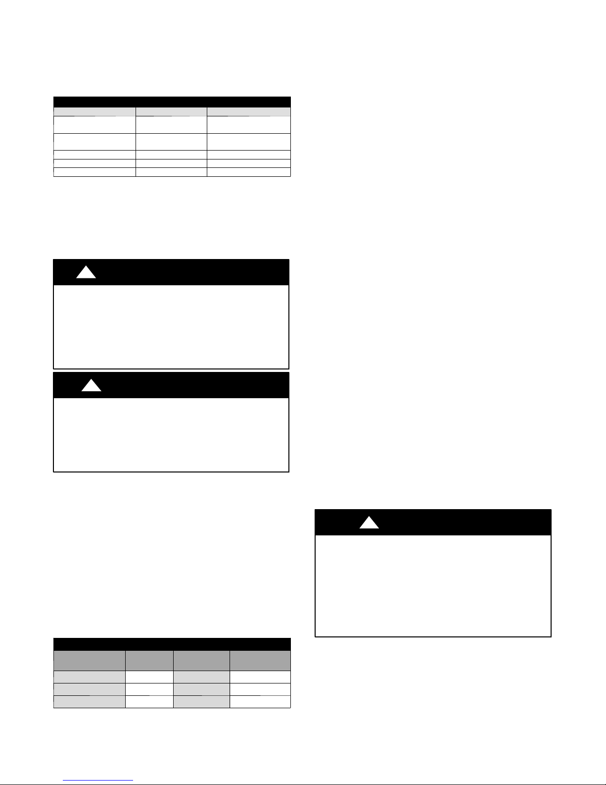
Table 1 – Recommended Mounting Pads
Unit Size Mounting Pad Pad Dime ns ions
GZ024 ACMP2436 24” x 36”
GZ036 ACMP2436 24” x 36”
GZ048 ACMP2436 24” x 36”
GZ060 ACMP2836 28” x 36”
GZ072 ACMP2836 28” x 36”
Fan Coil or Furnace Location
Refer to the Fan Coil or Furnace Installation Manual for complete
Details on indoor locations and clearances.
2
APPLICATION CONSIDERATIONS
Geothermal Systems
Closed loop and pond applications require specialized design
knowledge. No attempt at these installations should be made unless
the dealer has received specialized training.
Anti--freeze solutions are utilized when low evaporating conditions
are expected to occur. Refer to the Flow Center installation
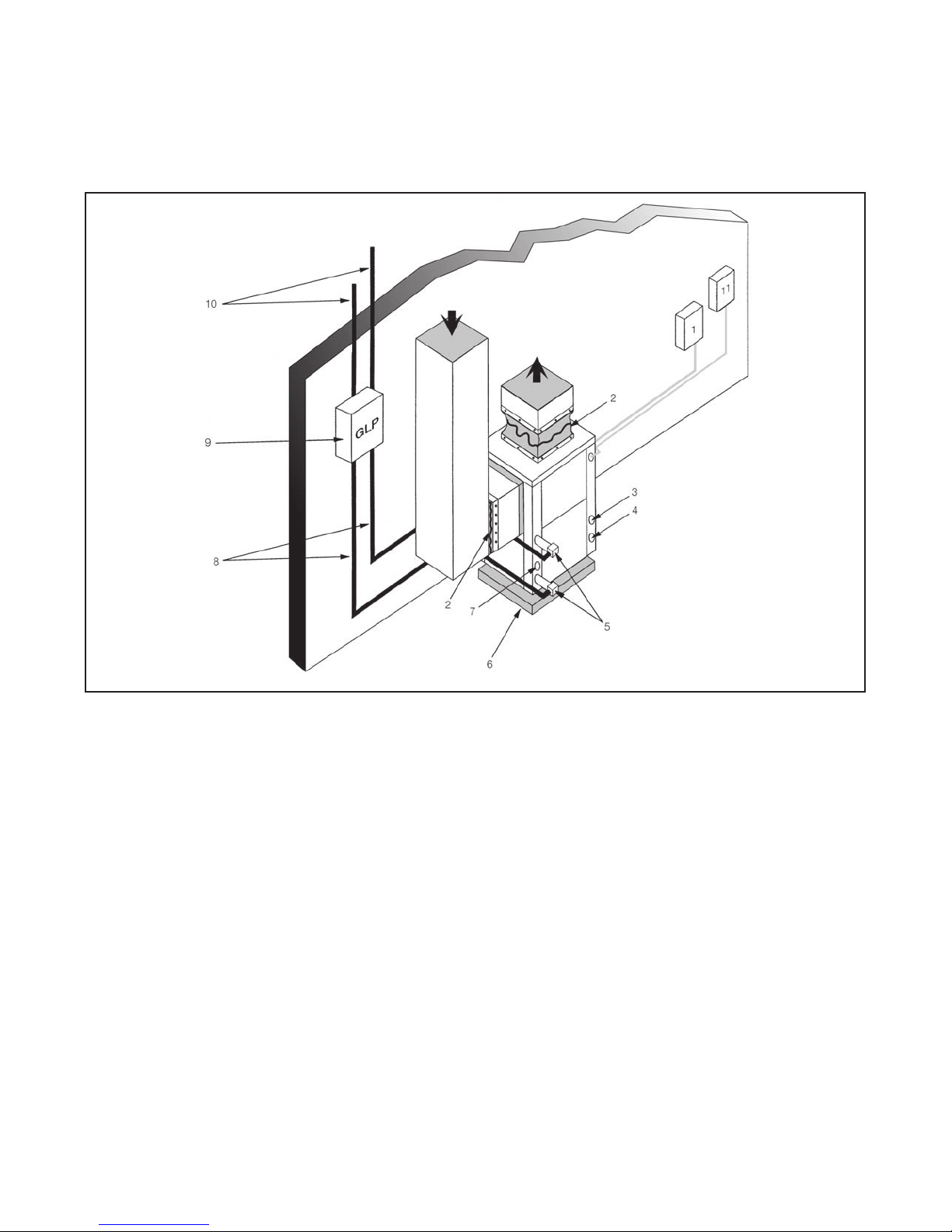
manuals for more specific instructions. (See Fig. 3)
Note: Package unit shown. GZ unit is connected to furnace or fan coil (see page 6).
(1) Line Voltage Disconnect (unit) (8) Ground Loop Connection Kit
(2) Flex Duct Connection (9) Ground Loop Pumping Package
(3) Low Voltage Control Connection (10) Polyethylene with Insulation
(4) Line Voltage Connection (11) Line Voltage Disconnect (electric heater)
(5) P/T Ports
(6) Vibration Pad
(7) Condensate Drain Connection
Fig. 3 -- Example Geothermal System Setup
Diagram shows typical vertical
package unit installation and is
for illustration purposes only.
Ensure access to Heat Pump is
not restricted.
A14132
3
Open Loop Well Water Systems
IMPORTANT: Table 2 must be consulted for water quality
requirements when using open loop systems. A water sample must
be obtained and tested, with the results compared to the table.
Scaling potential should be assessed using the pH/Calcium
hardness method. If the pH is <7.5 and the calcium hardness is
<100 ppm, the potential for scaling is low. For numbers out of the
range listed, a monitoring plan must be implemented due to
probable scaling.
Other potential issues such as iron fouling, corrosion, erosion and
clogging must be considered. Careful attention to water conditions
must be exercised when considering a well water application.
Failure to perform water testing and/or applying a geothermal heat
pump to a water supply that does not fall within the accepted
quality parameters will be considered a mis--application of the unit
and resulting heat exchanger failures will not be covered under
warranty. Where a geothermal system will be used with adverse
water conditions, a suitable plate--frame heat exchanger MUST be
used to isolate the well water from the geothermal unit.
Proper testing is required to assure the well water quality is suitable
for use with water source equipment.
In conditions anticipating moderate scale formation or in brackish
water, a cupronickel heat exchanger is recommended. Copper is
adequate for ground water that is not high in mineral content.
In well water applications, water pressure must always be
maintained in the heat exchanger. This is accomplished by
installing the water solenoid valve in the leaving / outlet water line.
When using a single water well to supply both domestic water and
the heat pump, care must be taken to insure that the well can
provide sufficient flow for both.
In well water applications, a slow closing solenoid valve must be
used to prevent water hammer (hammering or stuttering sound in
the pipeline). Solenoid valve should be connected across Y1 and
COND on the interface board for all. Make sure that the VA draw
of the valve does not exceed the contact rating of the thermostat.
(See Fig. 4)
The water solenoid valve should be installed in the leaving water
line. A flow regulator valve should be located after the solenoid to
set the flow rate. The suggested flow rate is 1.5 GPM per ton if the
Entering Water Temperature (EWT) is 50_F or above. If below
50_F EWT use 2 GPM per ton. Example, a 4 ton unit with 50_F
EWT would require a 6 GPM flow regulator. This would be part #
FR6 (Flow Regulator) and the 6 is the GPM. If example was with
48_F EWT part. Refer to the Open Loop Accessories section in the
Geothermal System Components Catalog for more part numbers.
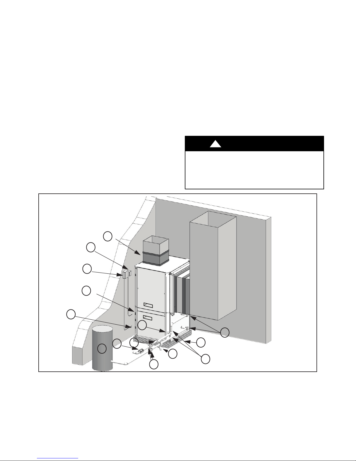
!
UNIT OPERATION HAZARD
Failure to follow this caution may result in equipment
damage or improper operation.
Discharge air configuration change is not possible on Heat
Pumps equipped with Electric Heat Option.
CAUTION
1
13
12
2
11
6
14
5
9
7
4
Note: Package unit shown. GZ unit is connected to furnace or fan coil (see page 6).
(1) Flex Duct Connection (8) Hose Kits (optional)
(2) Low Voltage Control Connection (9) Pressure Tank (optional)
(3) Vibration Pad (10) P/T Ports
(4) Ball Valves (11) Line Voltage Connection
(5) Solenoid Valve Slow Closing (12) Electric Heater Line Voltage Disconnect
(6) Condensate Drain Connection (13) Unit Line Voltage Disconnect
(7) Drain Valves (14) Flow Regulator
Fig. 4 -- Example Well Water System Setup
10
3
Typical Installation shown for
8
Illustrion purposes only.
Split unit not shown
A150775
4
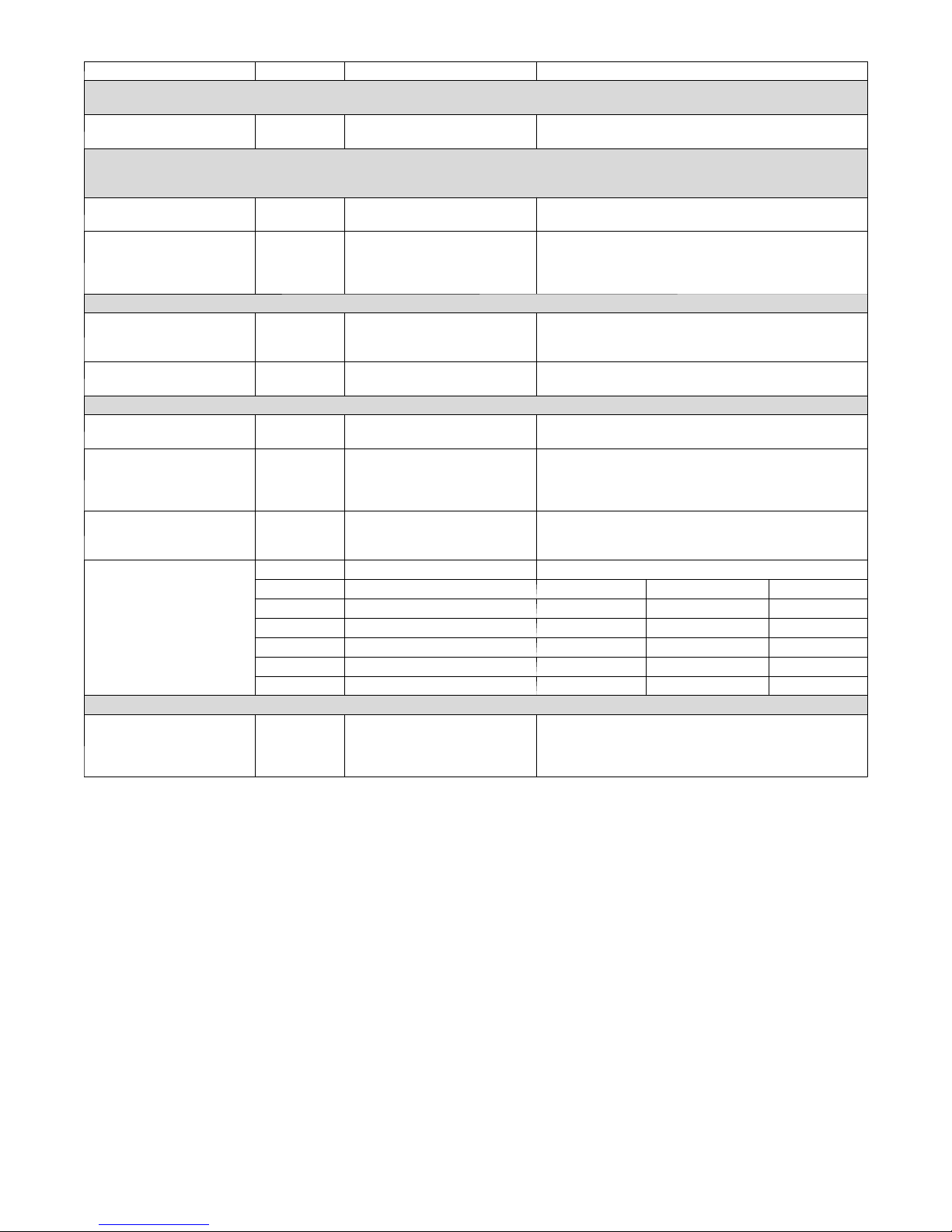
Table 2 – Water Quality Requirements for Open--Loop Geothermal Heat Pump System
Water Quality Parameter HX Material Closed Recirculating Open Loop and Recirculating Well
Scaling Potential - Primary Measurement
Above the given limits, scaling is likely to occur. Scaling indexes should be calculated using the limits below:
pH/Calcium Hardness
Method
Index Limits for Probable Scaling Situations - (Operation outside these limits is not recommended)
Scaling indexes should be calculated at 150°F for direct use and HWG applications, and at 90°F for indirect HX use.
A monitoring plan should be implemented.
Ryznar Stability Index All --
Langelier Saturation Index All --
Iron Fouling
Iron Fe² (Ferrous)
(Bacterial Iron Potential)
Iron Fouling All --
Corrosion Prevention
pH All
Hydrogen Sulfide (H2S) All --
Ammonia ion as hydroxide,
chloride, nitrate and sulfate
compounds
Maximum Chloride Levels
Erosion and Clogging
Particulate Size and
Erosion
NOTES:
S Closed recirculating system is identified by a closed pressurized piping system.
S Recirculating open wells should observe the open recirculating design considerations.
S NR - application not recommended
S "—" No design Maximum
All -- pH <7.5 and Ca Hardness <100ppm
6.0 - 7.5
If > 7.5 minimize steel pipe use
-0.5 to +0.5
If <-0.5 minimize steel pipe use.
Based upon 150°F HWG and Direct well,
84°F Indirect Well HX
<0.2 ppm (Ferrous)
All --
If Fe²* (ferrous) >0.2 ppm with pH 6-8, O2<5 ppm check
for iron bacteria
<0.5 ppm of Oxygen
Above this level deposition will occur
6-8.5
Monitor/treat as needed
Minimize steel pipe below 7 and no open tanks with pH <8
6-8.5
At H S>0.2 ppm, avoid use of copper and copper nickel
piping or HXs. Rotten egg smell appears at 0.5 ppm level.
Copper alloy (bronze or brass) cast components are OK
to <0.5 ppm
All -- <0.5 ppm
Maximum Allowable at Maximum Water Temperature
50°F 75°F 100°F
Copper -- <20 ppm NR NR
cupronickel -- <150 ppm NR NR
304 SS -- <400 ppm <250 ppm <150 ppm
316 SS -- <1000 ppm <550 ppm <375 ppm
Titanium -- >1000 ppm >550 ppm >375 ppm
All
<10 ppm of particles and a
maximum velocity of 1.8 m/s.
Filtered for maximum 841 micron [0.84 mm 20 mesh] size
<10 ppm (<1 ppm "sandfree" for reinjection) of particles
and a maximum velocity of 1.8 m/s. Filtered for maximum
841 micron [0.84 mm. 20 mesh] size. Any particulate that
is not removed can potentially clog components
5

TYPICAL INSTALLATIONS
Power
Disconnects
Air Handler
Vibration Isolator Pad
Fig. 5 -- Typical Split with Air Handler Installation
Power
Disconnects
Vibration Isolator Pad
Fig. 6 -- Typical Split with A--coil & Furnace Installation
6
MATCHED SYSTEM
The GZ geothermal splits have been tested and rated with Carrier
& Bryant air handlers (fan coils) and evaporator coils (for use with
furnaces).
Use air handler or cased coil from the list below and follow the
Installation Instructions for those components.
Geothermal and Air Handler or Cased Coil Match---Up
Geothermal Split Air Handler Cased Coil
GZ024
GZ036
GZ048 F(E/V)4***005 C(A/N)P(V/M)P4821
GZ060 F(E/V)4***006 C(A/N)P(V/M)P6024
GZ072 F(E/V)4***006 C(A/N)P(V/M)P6024
When using the GZ unit with a furnace, it is important to match the
CFM output of the furnace to the requirements of the GHP. For the
GZ072, the selected furnace must achieve at least 2200 CFM.
NOTE: The Infinity/Evolution Control may not prevent the
system from accepting a furnace with less airflow than required for
the GZ072. This is the responsibility of the installer.
F(E/V)4***003,
FB*024
F(E/V)4***003,
F(E/V)4***005
C(A/N)P(V/M)P2417
C(A/N)P(V/M)P3617
REFRIGERANT LINES
!
PERSONAL INJURY / ENVIRONMENTAL HAZARD
Failure to follow this warning could result in personal injury
or death.
Relieve pressure and recover all refrigerant before system
repair or final unit disposal.
Use all service ports and open all flow–control devices,
including solenoid valves.
!
ENVIRONMENTAL HAZARD
Failure to follow this caution may result in environmental
damage.
Federal regulations require that you do not vent refrigerant to
the atmosphere. Recover during system repair or final unit
disposal.
The installation of the copper refrigerant tubing must be done with
care to obtain reliable, trouble free operation. This installation
should only be performed by qualified refrigeration service and
installation personnel.
Refrigerant lines should be routed and supported so as to prevent
the transmission of vibrations into the building structure. 75 feet as
the maximum length of interconnecting refrigerant lines in split
system heat pumps. Beyond 75 feet, system losses become
substantial and the total refrigerant charge required can
compromise the reliability and design life of the equipment.
Refrigerant lines should be sized in accordance with those listed in
Table 3. Copper tubing must be clean and free of moisture and dirt
or debris. The suction and liquid lines should be insulated with at
least 3/8” wall, closed--cell foam rubber insulation or equivalent.
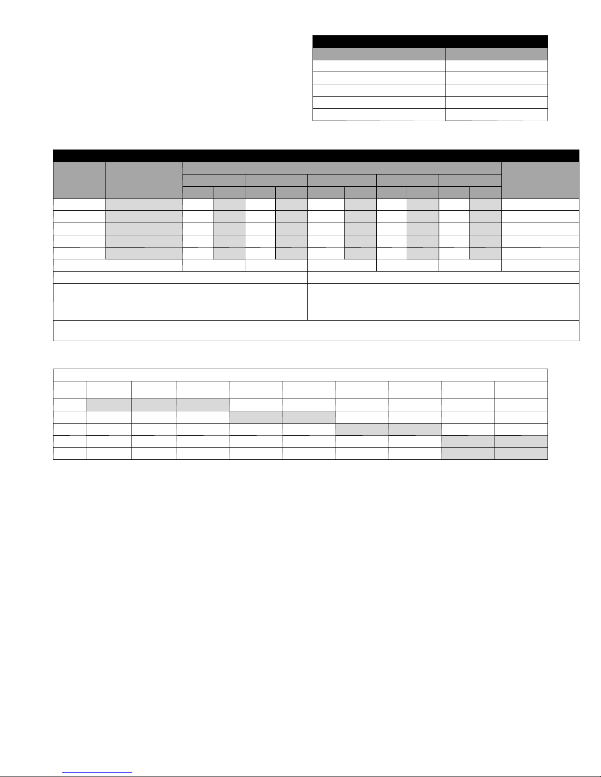
Unit Size Line Type
GZ024, 036 Suction 3/4 5/16
GZ048, 060, 072 Suction 7/8 5/16
All Valves Liquid 3/8 5/16
WARNING
CAUTION
Table 3 – Valve Sizing Chart
Valve Sizing Chart
Valve Conn.
Size
Allen Wrench
Size
Some points to consider are:
S Pressure drop (friction losses) in refrigerant suction lines reduces
system capacity and increases power consumption by as much as
2% or more, depending on the line length, number of bends, etc.
Pressure drop in liquid lines affects system performance to a lesser
degree, provided that a solid column of liquid (no flash gas) is
being delivered to the refrigerant metering device, and that the
liquid pressure at the refrigerant metering device is sufficient to
produce the required refrigerant flow.
S Oil is contin u ally bein g circulated with the refrigerant so , oil
return to the compressor is always a consideration in line sizing.
Suction lines on split system heat pumps are also hot gas lines in
the heating mode, but are treated as suction lin es for sizing
purposes. If the recommended suction lines sizes are used, there
should be no problem with oil return.
S Vertical lines should be kept to a minimum. Vertical liquid lines
will have a vertical liquid lift in either heating or cooling, and the
weight of the liquid head is added to the friction loss to arrive at
the total line pressure drop.
S Wherever possible, the air handler should be installed at a higher
elevation than the condensing section to aid with oil return to the
compressor.
Linear vs Equivalent Line Length
Linear Line Length -- is the actual measured length of the line
including bends. This is used to calculate the additional refrigerant
charge that must be added to the system.
Equivalent Line Length -- is the combination of the actual length
of all the straight runs and the equivalent length of all bends valves
and fittings in a particular line. The equivalent length of a bend,
valve or fitting is equal to the length of a straight tube of the same
diameter having the same pressure drop as the particular valve or
fitting. The ASHRAE Fundamentals Handbook provides tables for
determining the equivalent length of various bends, valves and
fittings.
Connecting Refrigerant Lines
S Use only ACR grade copper tubing and keep ends sealed until
joints are made.
S For b est performan ce, select routing of refrigerant lines for
minimum distance and least number of bends.
S Size lines in accordance with Table 5.
S Cut crimped ends off the air handler suction and liquid lines.
Connect and braze lines to the air handler.
NOTE: The air handler is factory supplied with a holding charge
of dry nitrogen.
S Connect and braze lines to service valves on the condensing
section.
!
UNIT DAMAGE HAZARD
Failure to follow this caution may result in equipment
damage or improper operation.
S Use a brazing shield
S Wrap service valves with wet cloth or heat sink material.
S Direct flame away from the valve body.
S Valve body temperature must remain below 250_Fto
protect the internal rubber “O” rings and seals.
S Use nitrogen purge while brazing.
Pressurize the refrigerant lineset and air handler to 150 lbs with dry
nitrogen through the ports provided on the self service valves.
Check lineset and unit connections for leaks. Once system integrity
is verified, evacuate lineset and air handler with a good vacuum
pump to 500 microns and hold for half hour.
IMPORTANT: Pumpdown must never be used with heat
pumps.
CAUTION
7
After verifying system integrity, slowly open service valve to allow
refrigerant to flow through system. Unit is pre--charged for 25’ of
line set. Refer to Tables 4, 5 and 6 to adjust and verify system
charge accordingly.
Table 4 – Liquid Line Charge per Linear Ft.
Liquid Line Charge pe r Linear Ft.
Liquid Line Size O.D. R410A oz per ft.
1/4 .25
5/16 .44
3/8 .60
1/2 1.15
5/8 1.95
Table 5 – Refrigerant Charge, Line Sizing & Capacity Multipliers
Refrigerant Charge, Line Sizing and Capacity Multiplier Chart
Model
GZ024 80 3/8 3/4 3/8 3/4 3/8 3/4 3/8 3/4 3/8 7/8 3/4
GZ036 86 3/8 3/4 3/8 3/4 3/8 3/4 3/8 7/8 3/8 7/8 3/4
GZ048 88 3/8 7/8 3/8 7/8 3/8 7/8 3/8 7/8 3/8 7/8 7/8
GZ060 115 3/8 1 --- 1 / 8 3/8 1 --- 1 / 8 3/8 1 --- 1 / 8 3/8 1 --- 1 / 8 3/8 1 --- 1 / 8 7/8
GZ072 127 3/8 1 --- 1 / 8 3/8 1 --- 1 / 8 3/8 1 --- 1 / 8 3/8 1 --- 1 / 8 3/8 1 --- 1 / 8 7/8
CAPACITY MULTIPLIER 1.00 .995 .990 .990 .980
Example 1: Example 2:
Model GZ036 with 45 ft. of equivalent length of 3//8” O.D. Liquid Lin e.
Total system charge = Factory charge + (45 ft --- 25 ft) X .60 oz/ft.
Total system charge = 86 oz + (20 ft x .60 oz/ft) = 98 oz.
Additional 12 oz of R410A refrigerant required.
Line Set Limitations: A 20 ft. Differential is the recommended limit without special considerations. For installations with 20 ---40 ft. Differential, it is recommended to add a
liquid lin e solen oid and, if the fan coil or furnace is above the GZ unit, add an inverted trap before line drop.
Factory R410A
Charge (oz)*
25 Ft. 35 Ft. 45 Ft. 50 Ft. 75 Ft.
LIQ. SUC LIQ. SUC LIQ. SUC LIQ. SUC LIQ. SUC
Refrigerant Line O.D. Size (Based on Equivalent Line Length)
Model GZ060 with 10 ft. of equivalent length of 3//8” O.D. Liquid Lin e.
Total system charge = Factory charge + (10 ft --- 25 ft) X .60 oz/ft.
Total system ch a rge =115 oz --- (15 ft x .60 oz/ft) = 106 oz.
Reduce charge 9 oz of R410A refrigerant is required.
Suction/Discharge
Vapo r Li ne
Table 6 – Charge Adjustments When Paired with Air Handlers
Charge Adjustments for GZ condensing section whe n paired with air handlers (oz)
Unit
GZ024 --- 1 1 --- 7 --- 8 --- --- --- --- ---
GZ036 --- --- --- 0 0 --- --- ---
GZ048 --- --- --- --- --- 5 5 ---
GZ060 --- --- --- --- --- --- --- --- 1 3 0
GZ070 --- --- --- --- --- --- --- --- 1 3 --- 6
Example: Model GZ048 condensing section paired with FV4CNF005L air handler with 45ft o f equivalent length of 3/8” O.D liquid Line.
Total system charge = factory charge + (charge adjustments for air handler)+ (45ft --- 25 ft) x .60 oz/ft.
Total system ch a rge = 88 oz + (5 oz ) + (20ft x .60 oz/ft) = 105 oz.
Additional 17 oz of R410A refrigerant required.
CNPV2417
FV4CNF003
FE4CNF003
FB4CMF024 CNPVP3617
FV4CNF003
FE4CNF003
CNPVP4821
FV4CNF005L
FE4CNF00FL
CNPVP6024
FV4CNF006
FE4CNF006
8
WATER PIPING
Supply and return piping must be as large as the unit connections
on the heat pump (larger on long runs).
!
UNIT OPERATION HAZARD
Failure to follow this caution may result in improper
equipment operation.
Never use flexible hoses of a smaller inside diameter than
that of the fluid connections on the unit.
GZ units are supplied with either a copper or optional cupronickel
water coax coil. Copper is adequate for ground water that is not
high in mineral content.
NOTE: Proper testing is recommended to assure the well water
quality is suitable for use with water source equipment. When in
doubt, use cupronickel. See Application Considerations notes on
page 4.
In conditions anticipating moderate scale formation or in brackish
water, a cupronickel heat exchanger is recommended.
Both the supply and discharge water lines will sweat if subjected to
low water temperature. These lines should be insulated to prevent
damage from condensation. All manual flow valves used in the
system must be ball valves. Globe and gate valves must not be
used due to high pressure drop and poor throttling characteristics.
CAUTION
Water Solenoid Valves
Open loop well water applications require a water solenoid valve.
The purpose of the valve is to allow water to flow through the
GHP only during operation.
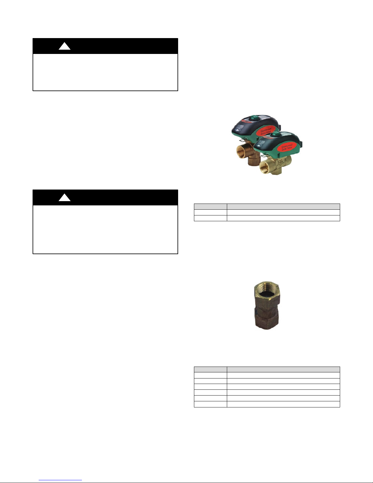
For ground water/open loop installations, solenoid valves
MVBR3F and MVBR4F are recommended due to its fast
opening/slow closing timing feature (see Fig. 7). This valve will
open in approximately 5 seconds. Solenoid valves that are slow
opening are not recommended as water in the unit’s coax may
freeze during start--up of a heating call. A frozen coax is not
covered under warranty. MVBR3 and MVBR4F valves are also
slow closing to eliminate potential water hammer.
Information on the MVBR3F and MVBR4F valves is shown
below.
A150629
Fig. 7 -- Solenoid Valves
!
EQUIPMENT DAMAGE AND/OR UNIT
OPERATION HAZARD
Failure to follow this caution may result in equipment
damage and/or improper operation.
Never exceed the recommended water flow rates as serious
damage or erosion of the water--to-- refrigerant heat
exchanger could occur.
Always check carefully for water leaks and repair appropriately.
Units are equipped with female pipe thread fittings.
NOTE: Teflon tape sealer should be used when connecting water
piping connections to the units to insure against leaks and possible
heat exchanger fouling.
NOTE: The unit is shipped with water connection O-- rings. A 10
pack of O-- rings (part #4026) can be ordered through Replacement
Components Division (RCD).
IMPORTANT: Do not over--tighten connections.
Flexible hoses should be used between the unit and the rigid
system to avoid possible vibration. Ball valves should be installed
in the supply and return lines for unit isolation and unit water flow
balancing (on open--loop systems).
CAUTION
Loop Pump Connections
Refer to the flow center installation manual for piping and wiring
instructions.
When using a flow center containing a variable speed pump, kit
#4129 is required.
Part Numb er Description
Table 7 – Water Solenoid Valves
MVBR3F Valve, motorized solenoid, forged brass ¾“ FPT, 24V
MVBR3F Valve, motorized solenoid, forged brass 1” FPT, 24V
Flow Regulator Valves
A flow regulator valve should be used in open loop / well water
applications to set the flow rate through the heat pump. The lowest
entering fluid temperature (EWT) expected should be used to
determine the flow rate per ton. 1.5 GPM per ton is acceptable for
50_F(10_C) EWT or higher. 2 GPM per ton should be used if
EWT is below 50_F(10_C).(SeeFig.8andTable8)
A150630
Fig. 8 -- Flow Regulator
Table 8 – Flow Regulators
Part Numb er Flow Regulator Valves
FR2 Valve, flow regulator, 3/4” FPT x 3/4” FPT, 2 GPM
FR3 Valve, flow regulator, 3/4” FPT x 3/4” FPT, 3 GPM
FR4 Valve, flow regulator, 3/4” FPT x 3/4” FPT, 4 GPM
FR5 Valve, flow regulator, 3/4” FPT x 3/4” FPT, 5 GPM
FR6 Valve, flow regulator, 3/4” FPT x 3/4” FPT, 6 GPM
FR7 Valve, flow regulator, 3/4” FPT x 3/4” FPT, 7 GPM
9

Typical Open Loop Piping
Open loop systems require a water solenoid valve to turn on the
water when the heat pump compressor is energized, and to turn off
the water when the compressor is off.
A slow--closing motorized valve (MVBR3F or MVBR4F) is
recommended to help reduce water hammer. A flow regulator
limits water flow to avoid using more water than the heat pump
requires, which wastes water and increases pumping costs. A hose
kit provides vibration isolation, as well as convenient fittings to
install P/T (pressure/temperature) plugs for checking water
Heat Pump
MVBR4F solenoid valve
1” rubber hose*
P/T Plug*
Heat Pump
Elbow*
LW T
1” hose barb
x 1” MPT*
1” MPT x 3/4” MPT
temperature and pressure drop at start--up and during
troubleshooting.
Fig. 9 shows the typical piping arrangement for a single solenoid
valve. For single speed heat pumps and smaller two--stage heat
pumps (3 tons and smaller), one valve is typical. For larger
two--stage heat pumps, there is an opportunity to save a significant
amount of energy (and avoid wasting water) with the use of two
solenoid valves, one for first stage, and both for second stage (Fig.
10).
MVBR Solenoid Valve Flow Regulator
1” ball valve
Pressure Tank
Piping to discharge***
†
EWT
1” hose barb
x 1” MPT*
*
Part of HK4MM hose kit
**
***
Consult local regulations for discharge requirements
†
††
Consider variable speed pump in place of pressure tank and pressure switch
1” ball valve
(optional)
Fig. 9 -- Single Solenoid Valve
Solenoid Valve
Stage One
Flow Regulator
Stage One
Ball Valve
From Heat Pump
Flow Regulator
Stage Two
Solenoid Valve
Stage Two
NOTE: Refer to Fig. 18. Wiring kit #4129 is recommended for easy 24 volt connection staging solenoids with compressor.
Fig. 10 -- Two Solenoid Valves
Submersible
††
Pump
10

HRP Water Piping
All hot water piping MUST be a minimum of 5/8” O.D. copper
tube to a maximum distance of 15 feet. For distances beyond 15
feet, but not exceeding 60 feet, use 1/2” copper tube. Separately
insulate all exposed surface of both connecting water lines with
3/8” wall closed cell insulation. Install isolation valves on supply
and return to the heat recovery. (See Fig. 11)
Water Tank Preparation
1. Turn off electrical or fuel supply to the water heater.
2. Attach garden hose to water tank drain connection and run
other end of hose out doors or to an open drain.
3. Close cold water inlet valve to water heater tank.
4. Drain tank by opening drain valve on the bottom of the
tank, then open pressure relief valve or hot water faucet.
5. Once drained the tank should be flushed with cold water
until the water leaving the drain hose is clear and free of
sediment.
6. Close all valves and remove the drain hose.
7. Install HR water piping.
Water Tank Refill
1. Open the cold water supply to the tank.
2. Open a hot water faucet to vent air from the system until
water flows from the faucet, then close.
3. Depress the hot water tank pressure relief valve handle to
ensure there is no air remaining in the tank.
4. Carefully inspect all plumbing for water leaks. Correct as
required.
5. Using the air bleed valve, purge all air from water piping,
allowing all air to bleed out until water appears at valve.
6. Before restoring the power or fuel supply to the water
heater, adjust the temperature setting on the tank
thermostat(s) to ensure maximum utilization of heat
available from the refrigeration system and to conserve the
most energy.
On tanks with thermostats and both upper and lower elements, the lower element should be turned down to 100_F,
while the upper element should be adjusted to 120_F. Depending upon the specific needs of the customer, you may
need to adjust the upper element differently.
On tanks with a single thermostat, lower the thermostat
setting to 120_F or the “LOW” position. After thermostat
adjustments are completed, replace access cover and restore
electrical or fuel supply to water heater.
IMPORTANT: Copper should be used for piping from HRP to
domestic water tank(s). Use 5/8” (16mm) O.D. copper or
larger. Refer to local codes for hot water piping. Insulate the
water lines between the GHP and the water heater with a
minimum of 3/8” (10mm) closed cell insulation.
Hot Water Out
Domestic Hot Water Supply
Domestic Cold Water Supply
Water Heater
(w/active elements)
Two Tank System (preferred)
Domestic Cold Water Supply
Hot Water Out
Cold Water In
One Tank System
Air Bleed Valve
Shut-off Ball Valve
HP
Air Bleed Valve
Shut-off Ball Valve
Water Heater
(w/active elements)
Package unit shown. GZ split unit arrangement similar with different water locations on unit .
Water Heater
(no active elements
pre-heat tank)
Fig. 11 -- HRP Water Piping
HP
A150174
11
 Loading...