

Carrier BT50RG-4.1, BT30RF-EXPR, BT50RGCH-4.1, BT50RS-4.1, BT50RSFMS-4.1 Service & Installation Manual
...
SERVICE &
INSTALLATION
MANUAL
MEDIUM
TEMPERATURE
VERTICAL
REFRIGERATORS
51-1337-02
01/03
CARRIER COMMERCIAL REFRIGERATION, INC.
Providing BEVERAGE-AIR • FRIGIDAIRE • KELVINATOR • UNIVERSAL NOLIN Products/Services
If additional information is necessary, call the factory.
Our toll free number is 1-800-684-1199.Technical assis-
tance engineers are willing to assist you in any way possible. Office hours are from 8:00 a.m. to 5:30 p.m., Eastern
Standard Time.
Important information is contained in this manual which should
be retained in a convenient location for future reference.
All data and information in this manual is subject to change without notice.
Manual effective for models produced January, 2003.
Starting serial number .
MODEL DESIGNATION INFORMATION
PART NO. MODELS STYLE CONDENSER SPECIAL USE
52-1923-01 BT30RF- EXPR SOLID ONE DOOR TOP MOUNT EXPLOSION PROOF
52-1958-02 BT30RF-FMS SOLID ONE DOOR TOP MOUNT FLAMMABLE MAT'L STORAGE
52-1993-33 BT30RG-4.1 GLASS ONE DOOR TOP MOUNT SCIENTIFIC GENERAL PURPOSE
52-1993-34 BT30RGCH-4.1 GLASS ONE DOOR TOP MOUNT CHROMATOGRAPHY
52-1993-35 BT30RS-4.1 SOLID ONE DOOR TOP MOUNT SCIENTIFIC GENERAL PURPOSE
52-1993-29 BT30RSFMS-4.1 SOLID ONE DOOR TOP MOUNT FLAMMABLE MAT'L STORAGE
52-1993-36 BT50RG-4.1 GLASS TWO DOOR TOP MOUNT SCIENTIFIC GENERAL PURPOSE
52-1993-37 BT50RGCH-4.1 GLASS TWO DOOR TOP MOUNT CHROMATOGRAPHY
52-1993-38 BT50RS-4.1 SOLID TWO DOOR TOP MOUNT SCIENTIFIC GENERAL PURPOSE
52-1993-30 BT50RSFMS-4.1 SOLID TWO DOOR TOP MOUNT FLAMMABLE MAT'L STORAGE
52-1993-39 BT80RG-4.1 GLASS THREE DOOR TOP MOUNT SCIENTIFIC GENERAL PURPOSE
52-1993-32 ST260RIR-4.1 SOLID ONE DOOR TOP MOUNT INCUBATOR
52-1993-41 ST30RGBB-4.1 GLASS ONE DOOR TOP MOUNT BLOOD STORAGE
52-1993-42 ST50RGBB-4.1 GLASS TWO DOOR TOP MOUNT BLOOD STORAGE
52-1991-64 T30MGP-4.1 GLASS ONE DOOR TOP MOUNT
52-1991-65 T30MSP-4.1 SOLID ONE DOOR TOP MOUNT
52-1991-66 T50MGP-4.1 GLASS TWO DOOR TOP MOUNT
52-1997-36 T50MGPR-4.1 GLASS TWO DOOR TOP MOUNT
52-1991-67 T50MSP-4.1 SOLID TWO DOOR TOP MOUNT
52-1991-68 T80MGP-4.1 GLASS THREE DOOR TOP MOUNT
52-1997-37 T80MGPR-4.1 GLASS THREE DOOR TOP MOUNT
52-1992-32 UMG30BS-4.1 GLASS ONE DOOR BOTTOM MOUNT
52-1992-33 UMG50BS-4.1 GLASS TWO DOOR BOTTOM MOUNT
52-1997-34 UMG50RS-4.1 GLASS TWO DOOR BOTTOM MOUNT
52-1992-34 UMG80BS-4.1 GLASS THREE DOOR BOTTOM MOUNT
52-1997-35 UMG80RS-4.1 GLASS THREE DOOR BOTTOM MOUNT
52-1992-35 UMH30BS-4.1 GLASS ONE DOOR BOTTOM MOUNT HEATED DOORS
52-1992-36 UMH50BS-4.1 GLASS TWO DOOR BOTTOM MOUNT HEATED DOORS
52-1992-37 UMH80BS-4.1 GLASS THREE DOOR BOTTOM MOUNT HEATED DOORS

TABLE OF CONTENTS-MED. TEMP. VERTICAL
MODEL CODES EXAMPLES..................................................2
HANDLING & INSTALLATION ..............................................4
TOP MOUNT, GLASS PULL DOOR (1-,2-,& 3-DR MODELS)
Dimensional Drawings..........................................................6
Refrigerator Specifications....................................................7
BOTTOM MOUNT, GLASS PULL DOOR (1-, 2-, 3-DR MODELS)
Dimensional Drawings..........................................................8
Refrigerator Specifications....................................................9
TOP MOUNT, SOLID PULL DOOR (1 & 2-DR MODELS)
Dimensional Drawings & Specifications ............................10
MAINTENANCE & REPAIR ......................................37
ELECTRICAL & REFRIGERATION INFORMATION
Medium Temperature Glass & Solid 1 Door ......................15
Medium Temperature Glass & Solid 2 Door ......................16
Medium Temperature Glass 3 Door ....................................17
Medium Temperature Solid 1 & 2 Door FMS......................17
ELECTRICAL & REFRIGERATION INFORMATION
BT30RF-FMS
Medium Temperature Solid 1 Door ....................................65
ELECTRICAL & REFRIGERATION INFORMATION
BT30RF-EXPR
Medium Temperature Solid 1 Door Refrigerator/Freezer ....69
ELECTRICAL & REFRIGERATION INFORMATION
ST260RI, ST260RIR
Incubator ............................................................................81
TROUBLESHOOTING ................................................93
COMPONENT IDENTIFICATION ........................100
PA RT S LIST ....................................................................109
TABLE OF CONTENTS 1

Medium Temperature Vertical Refrigerators
Introduction
These refrigerators have been designed to maintain a medium temperature environment. These multi-purpose refrigerators are available in one, two, and three-door solid or glass
door models.
Except for routine cleaning, these medium temperature cabinets will require little maintenance. In the unusual event that
repair should be necessary, this manual presents information
that is helpful in maintaining, diagnosing, and repairing these
cabinets.
2 INTRODUCTION
MODEL CODES – KELVINATOR & KELVINATOR SCIENTIFIC 3
MODEL CODES
Kelvinator Model Example: T30LGPR-4
T30LGP R-4
T = Top Mount
B = Bottom Mount
FS = Food Service
30, 50, 80 - Cubic Feet
L = Low Temp
M - Medium Temp
H = Hardening Cabinet
G= Glass Door
S = Solid Door
P = Pull Door
S = Sliding Door
Q = Quadrant Pull Door
R = Remote
E = Export
ET = Export Transformer
Customer Variations:
BR = Baskin Robbins
DQ = Dairy Queen
DQL = Dairy Queen Light Duty
4 = Revision Level
Kelvinator Scientific Model Example: ESTL50RSFMS-4
ESTL50RSFMS -4
E = Export
ET = Export (Transformer)
S = Scientific
B = Base Scientific
T = Top Mount
B = Bottom Mount
C = Chest
L = Hardening Cabinet
30, 50, 80 =
Cubic Feet
F = Freezer
R = Refrigerator
G = Glass Door
S = Solid Door
I = Incubator (Solid Door)
FMS = Flammable Material Storage
CH = Chromatography
BB = Blood Bank
EXPR = Explosion Proof
R = Recorder on Incubator
Customer Variations:
XXX
4 = Revision Level
4 MODEL CODES – UN
MODEL CODES
Universal Nolin Model Example: UMG50BS-4
UMG50B S-4
U = Upright
S = Scientific (upright)
L = Low Temp.
M = Med Temp.
H = Heated Glass (medium temp.)
G = Glass
S = Solid
O = Open
T = Sliding Glass Door (track)
30, 50, 80 =
Cubic Feet
R = Remote on Bottom Mounted Upright
U - Remote on Top Mounted Upright
T = Top Mounted Compressor
B = Bottom Mounted Compressor
S = Single Facing (sliders)
D = Double Facing
S = 115V / 60 Hz.
D = 208/230V / 60 Hz. / 1 Ph.
P = 208V / 60 Hz. / 3 Ph.
T = Transformer
F = 220V / 50 Hz.
4 = Revision Level
SECTION I – HANDLING & INSTALLATION
HANDLING & INSTALLATION 5
FREIGHT DAMAGES & SHORTAGES
The cabinet was inspected and
packaged at the factory, and should
arrive in excellent condition.The transportation company or other parties involv ed in the shipment are responsible for loss and/or damage.Always make an inspection before and after uncrating. Inspect the crated
unit(s) before locating (preferably at the point of
unloading by the transportation company).
INSPECTING FOR DAMAGES
Always use care when removing shipping
tape, blocks, pads, hardware or other material until you are satisfied that the unit is completely
operational.Contact the factory if technical assistance
is required.
Check the cartons or containers.If these are damaged
in any way, open them and inspect the contents in the
driver’s presence. If damage is detected:
1. Have the driver note the nature and extent of the
damage on the freight bill.
2. Notify the transpor tation company at once to request
an inspection. Carrier claim policies usually require
inspections to be made within 15 days of delivery.
3. If damage is noticed, file a claim with the transpor ta-
tion company.
FILING A CLAIM
File a claim for loss at once with the transportation company for:
A. A cash adjustment; B.Repairs; or C. Replacement.
When filing your claim, retain all packaging materials
and receipts.
HANDLING THE CABINET
The refrigeration system of the cabinet is
designed to operate with the cabinet located
on a level surface. Do not tilt the cabinet more than
10° to any side. If the cabinet must be tilted on an
angle for handling or moving purposes, allow it to sit in
an upright position 30 minutes prior to starting.
CHOOSING A LOCATION
This model cabinet should be situated to allow proper air
circulation. These cabinets require a 2" minimum clearance behind for proper air circulation.
The cabinet must be installed on sturdy, solid, level floor.
The cabinet must be located so it can be plugged into a
properly grounded three-prong electrical outlet of 115
volt, 60 hz.The electrical outlet should not be controlled
by a wall switch which might be turned off accidentally.
UNCRATING THE CABINET
The cabinet should be moved as close as possible to the
operating location before removing crate base. Be sure
to follow the steps in the “INSPECTING FOR DAM-
AGES ”instructions.
INSTALLING THE CABINET
(Models with Top Mounted Compressor)
Whenever possible leave the crate base on the cabinet
until it is moved close to the final position.When it is necessary to move the cabinet through a doorway, it may be
necessary to remove the crate base.
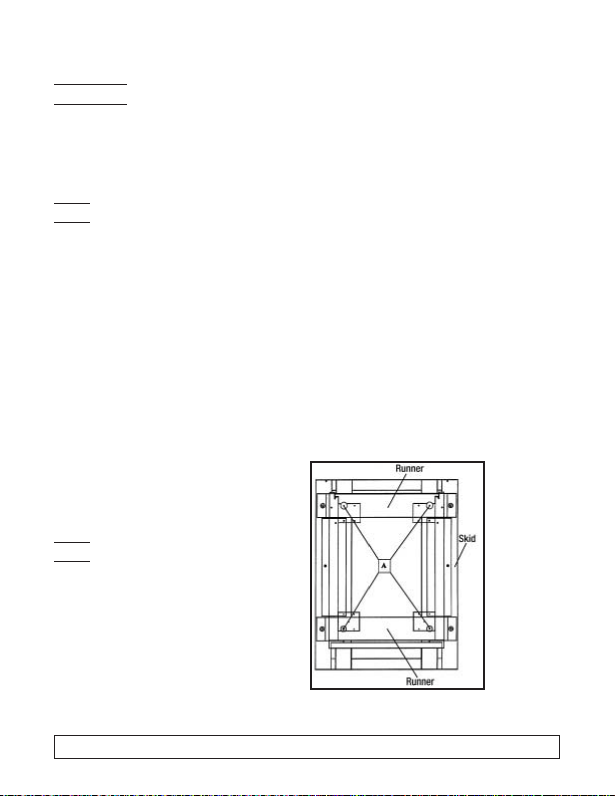
Wood runners are provided on the underside of the cabinet for ease in sliding. These runners should be left
attached to the cabinet when the crate base is removed
and should remain attached until after the legs are
installed.The cabinet can then be pushed around more
easily without scratching the floor.The runners also prevent damage to the electrical receptacle and condensate pan hardware on the cabinet bottom.
After the cabinet has been moved to the approximate
final location, remove the package containing the legs
from the cabinet interior. Tape the doors to prevent
accidental opening when handling. Raise the sides of
the cabinet high enough to mount the legs at the locations provided on the bottom of the cabinet.
IMPORTANT:
AFTER REMOVAL
OF WOOD RUNNER, REPLACE
BOLT “A” INTO
LEG MOUNTING
BRACKETS. THIS
IS EXTREMELY
IMPORTANT TO
THE SECURE
ATTACHMENT OF
THE CABINET
LEG. THERE
MUST BE FOUR
(4) BOLTS
SECURING EACH
LEG.
Level the cabinet by means of the leg adjustments.
Cabinet doors are self-closing, and the cabinet must be
level to operate properly.
NOTE:
IMPORTANT:
NOTE:
6 HANDLING & INSTALLATION
CONDENSATE PAN
INSTALLATION INSTRUCTIONS
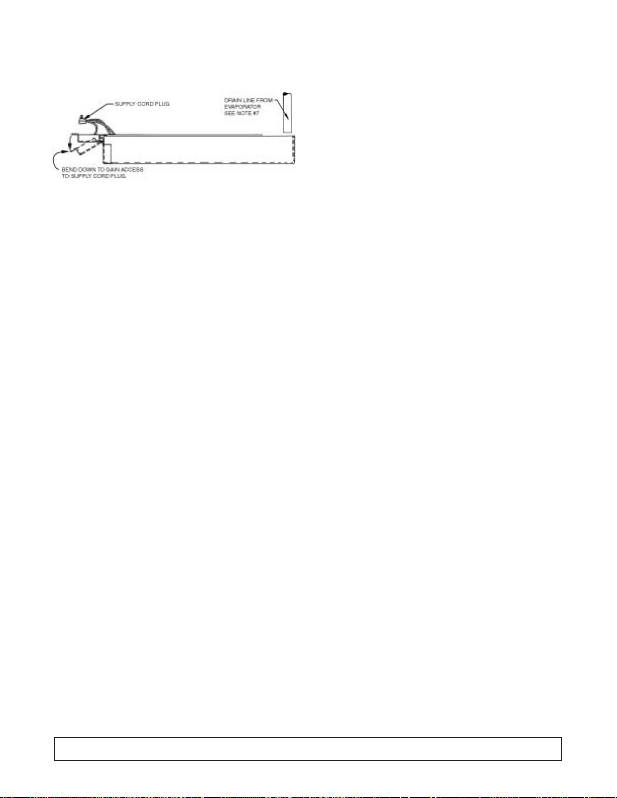
MAKE SURE THE CABINET IS DISCONNECTED
FROM ITS POWER SOURCE
1. Remove and discard protective cover over electrical
receptacle on bottom of cabinet
2. Bend down front part of housing. (See above.)
3. Insert condensate evaporator pan assembly into the slide
supports on the underside of the cabinet by pushing
toward back of cabinet until it stops.
4. Plug supply cord into receptacle in underside of cabinet.
5. Bend up front part of housing. Line up slot with rivnut in
cabinet bottom and insert thumbscrew through slot onto
rivnut in cabinet bottom. Insert thumb screw through slot
onto rivnut and tighten.
6. The assembly will now operate when power is supplied to
the cabinet.
7. Inspect rear of cabinet to ensure that the drain line from
the evaporator is properly positioned over the condensate pan.
On top mount models, allow a minimum of twelve (12) inches between the top of the cabinet and ceiling and two (2)
inches from the back of the cabinet to the wall.
(Models with Bottom Mounted Compressor)
Remove the crate base mounting clips located behind the
front grill.Slide the cabinet forward on the crate base to clear
the rear mounting clips.
After removing the crate base, move the cabinet into location.Make sure the cabinet is lev el to ensure operation of the
“self-closing” doors.
Allow a minimum of two (2) inches between the back of the
cabinet and the wall for proper air circulation through the
condensing unit.
CABINET STARTUP
Once the cabinet has been located in its permanent location
and the proper power and grounding have been provided,
the following items must be checked or completed:
1. Cut and remove the compressor hold-down band (if
applicable) so the compressor “floats” freely.
2. Check for traces of oil on the compressor pan which could
mean a broken or leaking refrigeration line.
2. UNDER NO CIRCUMSTANCE SHOULD THE COM-
PRESSOR BE STARTED WHEN OIL IS PRESENT
UNTIL INSPECTED BY A SERVICE TECHNICIAN.
3. INSPECT THE FACTORY WIRING FOR TERMINALS
THAT MIGHT HAVE VIBRATED LOOSE IN SHIPPING.
TIGHTEN ALL SCREW-TYPE TERMINALS.
4. Check the refrigeration lines to see that they are “free”
and no damage was done during shipping.
5. Check fan blade(s) for “free” operation.
6. Turn on the main power switch. Once the compressor
starts, the voltage should be checked at the compressor
terminals to determine if there is proper voltage to the
compressor.The voltage should not exceed 10% abov e or
below the rated compressor voltage.
EXAMPLE: If the voltage reads 115 volts with no load and it
drops below 103 volts when the compressor starts, it
may indicate that the supply wiring is too small or that
the wire run is too long.
7. Make sure that the drain line has not been dislodged or
broken during shipping and that the drain trap terminates properly in the condensate pan or floor drain.
(See Condensate Pan on top mounted compressor.)
8. Listen for any unusual noise such as lines vibrating, etc.
Correct problem by tightening screws, slightly bending
tubing, etc.
9. Check proper tension on doors. (See Door Torque
Adjustment.)
10. Cabinet should not be loaded with product until cabinet
has operated for 24 hours and reached desirable storage temperature.
THERMOSTAT SETTINGS
The refrigerator is shipped from the factory with a thermostat
setting of approximately the mid-point of the operating
range. Final thermostat setting must be made in the field.
Allow the cabinet to operate until the compressor cycles on
the thermostat. The normal operating temperature range for
the refrigerator is:
32°F to 55°F (0°C to 13°C)
NOTE:DO NOT OPERATE THE CABINET WITH THERMO-
STAT SETTINGS BELOW 32°F (0°C).
The thermostat is easily adjusted with a standard screwdriv-
er. The thermostat has settings 1 through 7, tur n the thermostat to a higher number to lower the cabinet temperature.
The thermostat is located behind the evaporator front grill
and can be adjusted through the grill. On some models the
thermostat is located in the electrical box at the top of the
cabinet.
SCIENTIFIC CONTROL AND
ANNUNCIATOR PANELS
Cabinets for Scientific use may be equipped with a v ariety of
optional control, alarm, and recorder devices. Each cabinet
is shipped with the appropriate operators manual for the
device installed on the cabinet.These operator manuals pertain to the set-up and basic operation of the control panel
devices. For more comprehensive operation, repair, and
maintenance information refer to the control panel service
manual part number 51-0170-01.
FIGURE 2
GROUNDING INSTRUCTIONS/SERIAL RATING PLATES 7
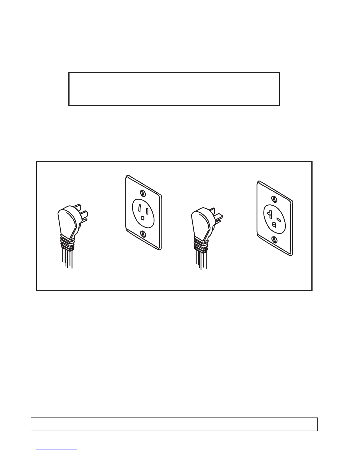
GROUNDING INSTRUCTIONS
This appliance is equipped with a three-prong
(grounding) plug for your protection against shock
hazards.The appliance should be plugged directly into
a properly grounded three-prong receptacle.
Where a two-prong wall receptacle is encountered, it
must be replaced with a properly grounded three
prong receptacle in accordance with the National
Electrical Code and local codes and ordinances. The
work must be done by a licensed electrician.
IMPORTANT
Do not under any circumstances cut or remove
the round grounding prong from the equipment plug.
WARNING
Consult a licensed electrician if you have any doubt about the grounding
of your wall receptacle. Only a licensed electrician can determine the
polarization of your wall receptacle. Only a properly installed three-pronged
wall receptacle assures the proper polarization with the equipment plug.
SERIAL RATING PLATES
Serial Number Rating Plates on each vertical cabinet
are located on the inside upper left hand corner.This
plate contains all technical data necessary to the oper-
ation of the cabinet. Warranty administration is based
on the serial number as printed on the rating plate.
15 Amp
20 Amp
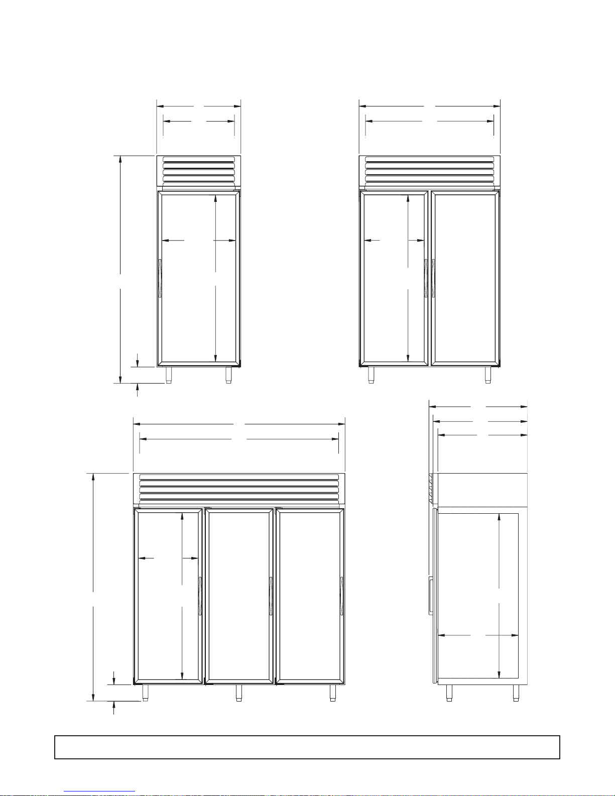
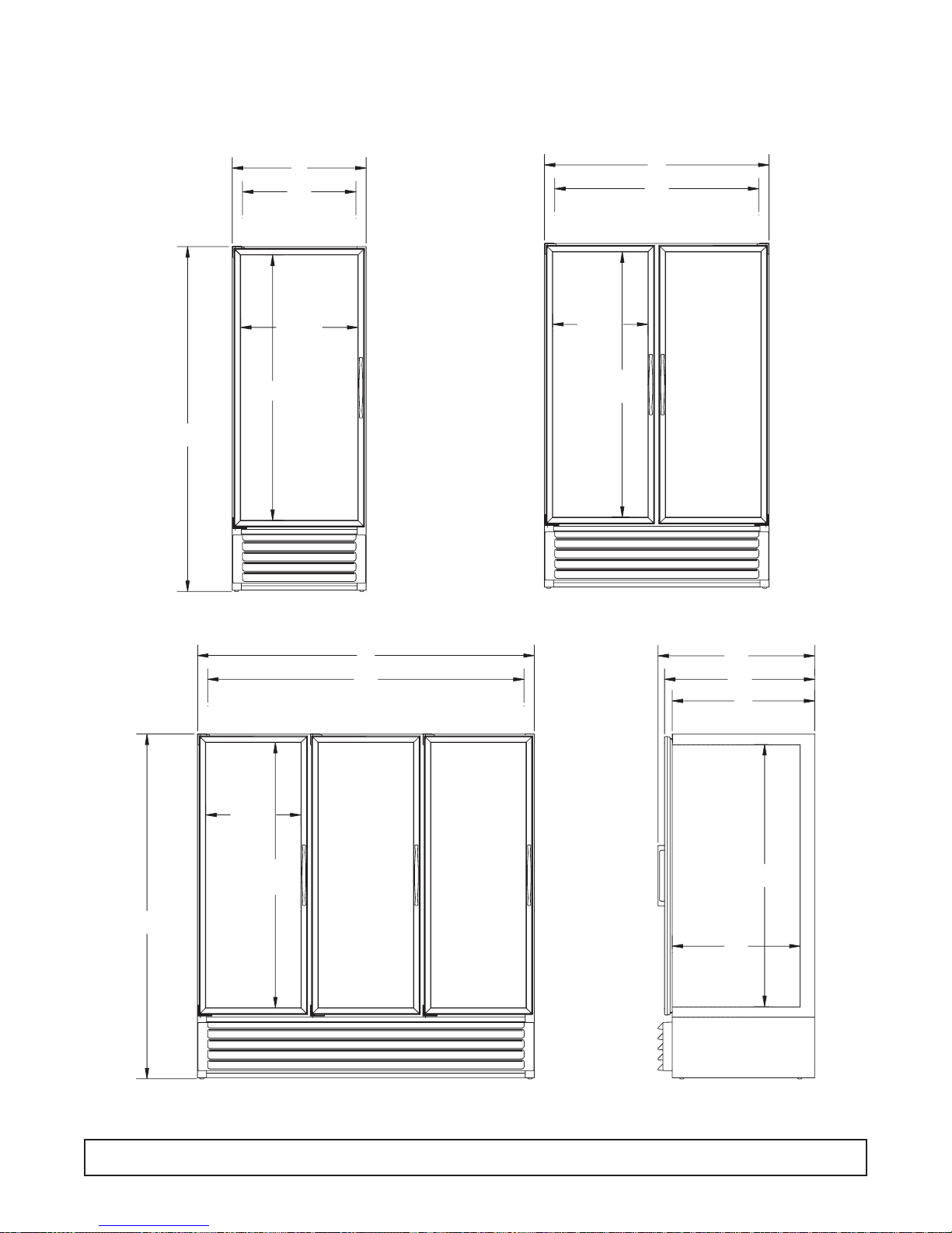
Medium Temperature, Top Mount, Glass Pull Door
Refrigerators Dimensional Drawings
8TOP MOUNT GLASS PULL DOOR DIMENSIONAL DRAWINGS
833/4
61
GLASS
TYP.
52
1
/4
47
INTERIOR
31
261/4
INTERIOR
3
/4
26
GLASS
61
GLASS
6
5
21
GLASS
TYP.
/8
1
/4
36
78
1
/4
73
INTERIOR
5
21
/8
GLASS
TYP.
61
3
83
/4
6
GLASS
TYP.
343/4
33
INTERIOR
295/8
INTERIOR
605/8
SIDE VIEW
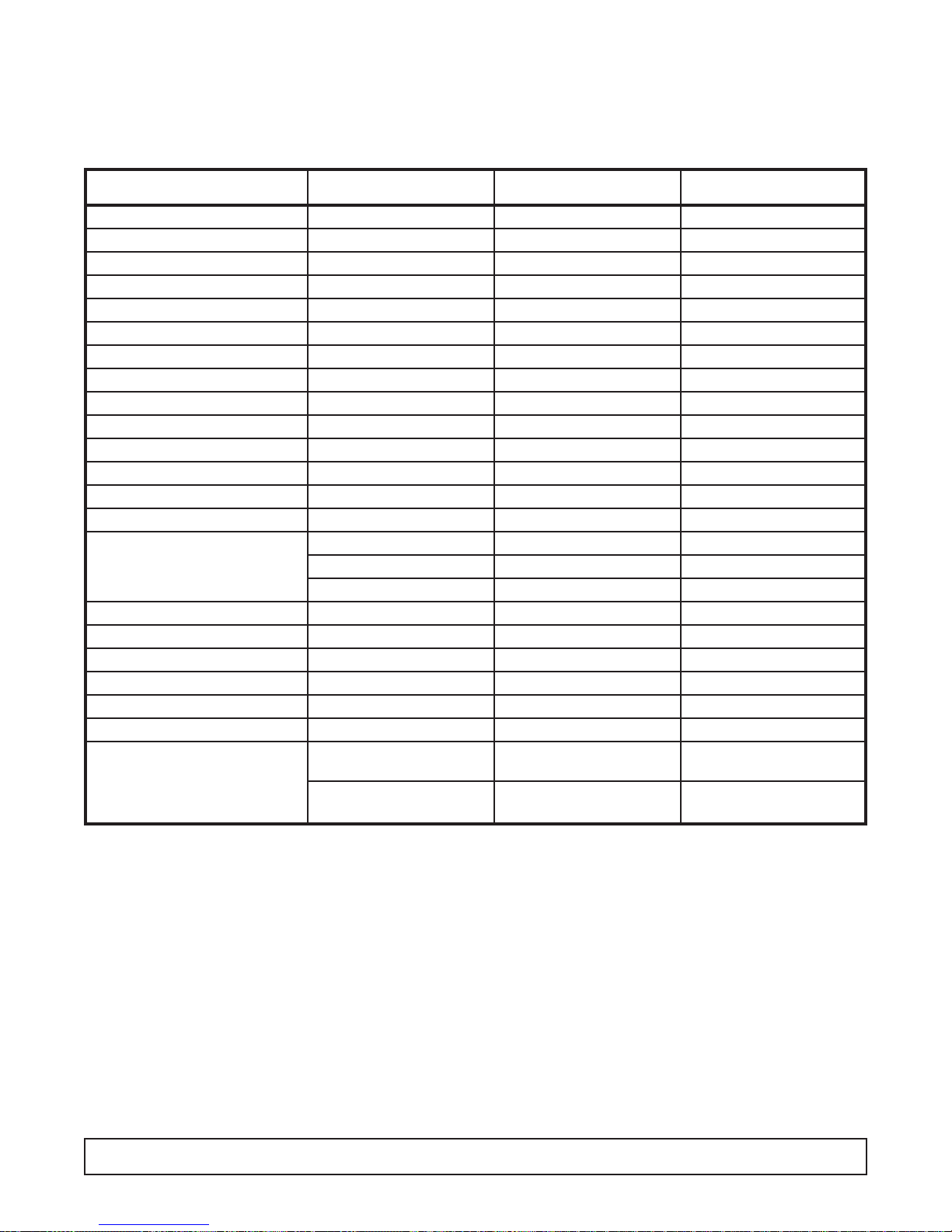
Medium Temperature, Top Mount, Glass Pull Door
Refrigerators Specifications
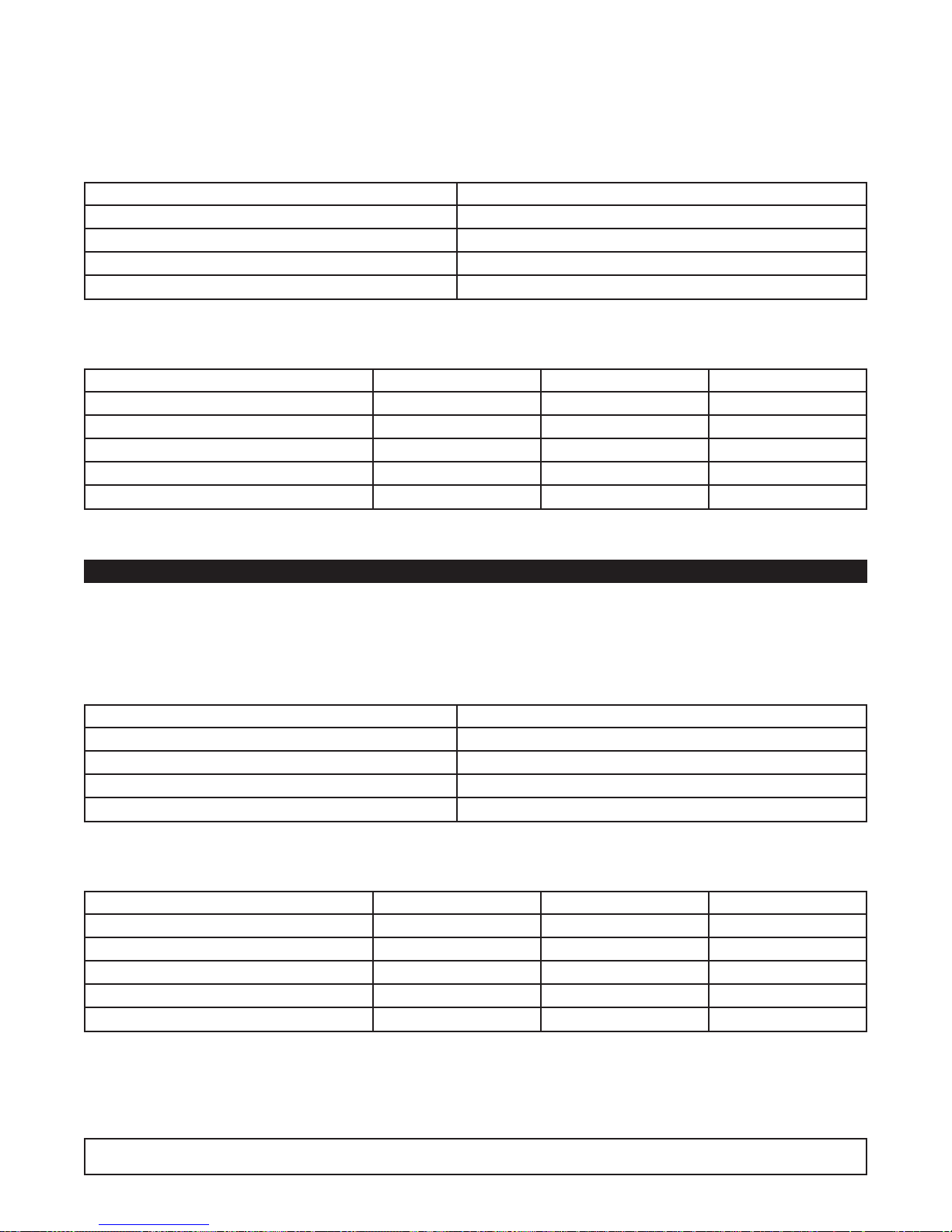
TOP MOUNT GLASS DOOR REFRIGERATOR SPECIFICATIONS 9
Specification 1-Door 2-Door 3-Door
Compressor Mount Top Top Top
Temperature Range 32° to 55° (0° to 13°C) 32° to 55° (0° to 13°C) 32° to 55° (0° to 13°C)
Number of Doors 1 2 3
Door Construction Double Pane Double Pane Double Pane
Hinge Type Torsion Bar Torsion Bar Torsion Bar
Insulation - CFC-Free Foam-in-Place Urethane Foam-in-Place Urethane Foam-in-Place Urethane
Wall Thickness 2 3/8" 2 3/8" 2 3/8"
Capacity - Gross 27.3 ft.
3
49.1 ft.
3
76.2 ft.
3
Shipping Weight (Approx.) 470 lbs. 640 lbs. 870 lbs.
Compressor BTUH/-10°F Evap. 2400 5400 5400
Condenser Type Fin & Tube Forced Air Fin & Tube Forced Air Fin & Tube Forced Air
Evaporator Type Fin & Tube Forced Air Fin & Tube Forced Air Fin & Tube Forced Air
Refrigerant Type R-404A R-404A R-404A
Refrigerant Control Expansion Valv e Expansion Valve Expansion Valv e
Amp Rating 9.5 12.1 14.5
11.2 BT30RG & ST30RGBB 13.8 BT50RG & ST50RGBB 16.0BG80RG
13.2 BT30RGCH 15.8 BT50RGCH
Electrical Specs. (V / Hz / Ph) 115 / 60 / 1 115 / 60 / 1 115 / 60 / 1
NSF NSF7 NSF7 NSF7
UL & CSA Listed Yes Yes Yes
Interior Finish Baked Enamel, Coved Corners Baked Enamel, Coved Corners Baked Enamel, Coved Corners
Exterior Finish Baked Enamel Baked Enamel Baked Enamel
Lighting
2 Insul. 1500 Milliamp Fluor. Lamps 3 Insul. 1500 Milliamp Fluor. Lamps 4 Insul. 1500 Milliamp Fluor. Lamps
Electrical Information 15 Amp Service Cord 20 Amp Ser vice Cord 20 Amp Ser vice Cord
w/NEMA 5-15P Plug w/NEMA 5-20 Plug w/NEMA 5-20P Plug
20 Amp Cord BT30RGCH
w/NEMA 5-20P Plug
Medium Temperature, Bottom Mount, Glass
Pull Door Refrigerators Dimensional Drawings
10 BOTTOM MOUNT DIMENSIONAL DRAWINGS
61
GLASS
TYP.
52
1
47
/4
INTERIOR
31
1
26
/4
INTERIOR
5
21
263/4
GLASS
61
GLASS
3
/4
79
GLASS
TYP.
/8
78
1
/4
73
INTERIOR
5
/8
21
GLASS
TYP.
61
GLASS
TYP.
3
/4
79
1
36
/4
343/4
33
295/8
INTERIOR
SIDE VIEW
5
/8
60
INTERIOR
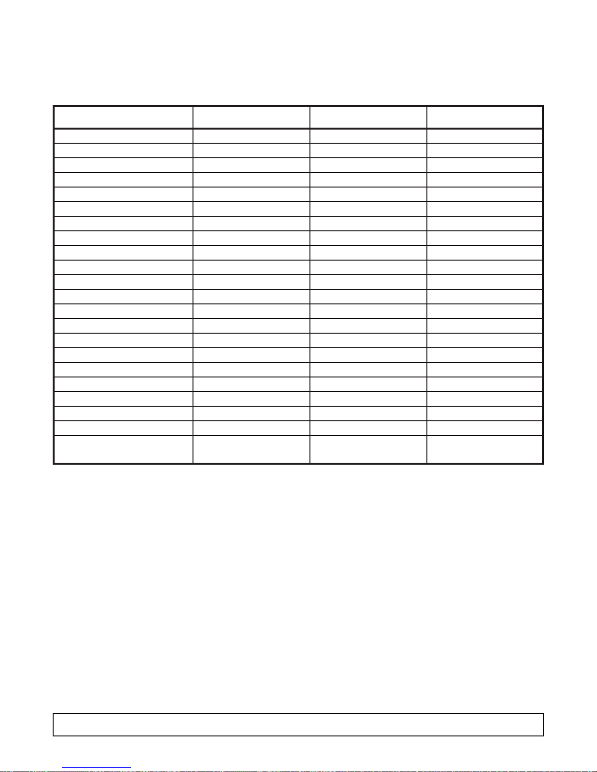
Medium Temperature, Bottom Mount, Glass
Pull Door Refrigerators Specifications
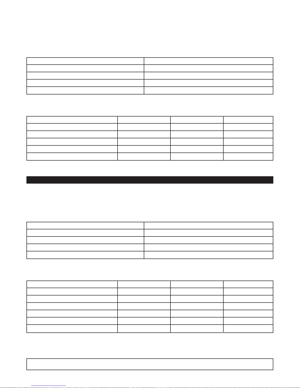
BOTTOM MOUNT REFRIGERATOR SPECIFICATIONS 11
Specification 1-Door 2-Door 3-Door
Compressor Mount Bottom Bottom Bottom
Temperature Range 32° to 55° (0° to 13°C) 32° to 55° (0° to 13°C) 32° to 55° (0° to 13°C)
Number of Doors 1 2 3
Door Construction Double Pane Double Pane Double Pane
Hinge Type Torsion Bar Torsion Bar Torsion Bar
Insulation - CFC-Free Foam-in-Place Urethane Foam-in-Place Urethane Foam-in-Place Urethane
Wall Thickness 2 3/8" 2 3/8" 2 3/8"
Capacity - Gross 27.3 ft.
3
49.1 ft.
3
76.2 ft.
3
Shipping Weight (Approx.) 488 lbs. 640 lbs. 724 lbs.
Compressor BTUH/-10°F Evap. 2400 5400 5400
Condenser Type Fin & Tube Forced Air Fin & Tube Forced Air Fin & Tube Forced Air
Evaporator Type Fin & Tube Forced Air Fin & Tube Forced Air Fin & Tube Forced Air
Refrigerant Type R-404A R-404A R-404A
Refrigerant Control Expansion Valv e Expansion Valve Expansion Valv e
Amp Rating 9.5 12.1 14.5
Electrical Specs. (V / Hz / Ph) 115 / 60 / 1 115 / 60 / 1 115 / 60 / 1
NSF NSF7 NSF7 NSF7
UL & CSA Listed Yes Yes Yes
Interior Finish Baked Enamel, Coved Corners Baked Enamel, Coved Corners Baked Enamel, Coved Corners
Exterior Finish Baked Enamel Baked Enamel Baked Enamel
Lighting
2 Insul. 1500 Milliamp Fluor. Lamps 3 Insul. 1500 Milliamp Fluor. Lamps 4 Insul. 1500 Milliamp Fluor. Lamps
Electrical Information 15 Amp Service Cord 20 Amp Ser vice Cord 20 Amp Ser vice Cord
w/NEMA 5-15P Plug w/NEMA 5-20P Plug w/NEMA 5-20P Plug
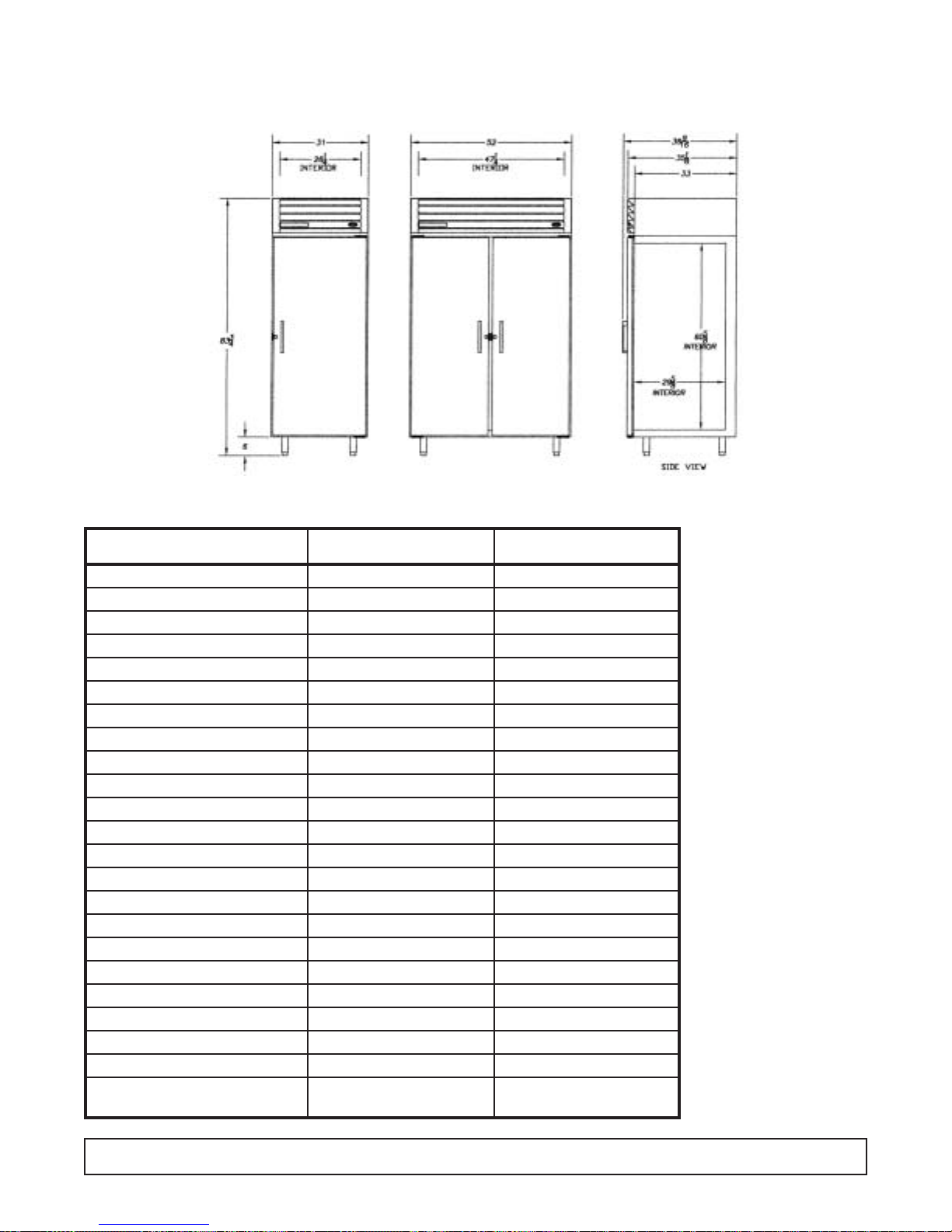
12 TOP MOUNT SOLID DOOR DRAWINGS & SPECIFICATIONS
Medium Temperature, Top Mount, Solid Pull Door
Dimensional Drawings
Specification 1-Door 2-Door
Compressor Mount Top Top
Temperature Range 32° to 55° (0° to 13°C) 32° to 55° (0° to 13°C)
Number of Doors 1 2
Door Construction Foam-In-Place Foam-In-Place
Hinge Type Camlift Camlift
Insulation Foam-in-Place Urethane Foam-in-Place Urethane
Wall Thickness 2 3/8" 2 3/8"
Capacity - Gross 27.3 ft.
3
49.1 ft.
3
Shipping Weight (Approx.) 440 lbs. 604 lbs.
Compressor BTUH/-10°F Evap. 2126 2126
Condenser Type Fin & Tube Forced Air Fin & Tube Forced Air
Evaporator Type Fin & Tube Forced Air Fin & Tube Forced Air
Refrigerant Type R-404A R-404A
Refrigerant Control Expansion Valv e Expansion Valvee
Amp Rating (80° Running) 8.7 8.7
8.9 BT30RS 8.9 BT50RS
Electrical Specs. (V / Hz / Ph) 115 / 60 / 1 115 / 60 / 1
NSF NSF7 NSF7
UL Listed Yes Yes
Interior Finish Baked Enamel, Coved Corners Baked Enamel, Coved Cornerss
Exterior Finish Baked Enamel Baked Enamel
Compressor Make Tecumseh Tecumseh
Electrical Information 15 Amp Service Cord 15 Amp Ser vice Cord
w/NEMA 5-15P Plug w/NEMA 5-15P Plug
Refrigerator Specifications

SECTION II
Compressor Model Number Copeland ASE24C3E-IAA
Recommended Operating Temp. Range 32°F to 55°F (0°C to 13°C)
Cabinet V olts 115
Expansion Device Sporlan FBS 1/4C BP40
Charge Refrig.Type / Oz. / Grams R404A / 23 / 652.0
ELECTRICAL & REFRIGERATION SPECIFICATIONS
Medium Temp., Glass, 1-Door Refrigerators
SYSTEM COMPONENTS
AMBIENT 70°F / 21.1°C 80°F / 27°C 90°F / 32.5°C
Cavity Temp. (F/C) 40 / 4 40 / 4 41 / 5
Suction Pressure (PSIG / Kpa) 44 / 303 45 / 317 49 / 338
Discharge Pressure (PSIG / Kpa) 211 / 1455 237 / 1634 269 / 1855
Compressor Amps 6.3 6.3 6.5
Total Refrigeration Amps 8.7 8.8 9.0
SYSTEM PERFORMANCE
NOTE: REFER TO SERIAL DATA PLATE FOR REFRIGERANT TYPE & CHARGE.
Compressor Model Number Americold HP121-1-3087
Recommended Operating Temp. Range (F/C) 32°F to 55°F (0°C to 13°C)
Cabinet V olts 115
Expansion Device Capillary .054 x 7"
Charge Refrig.Type / Oz. / Grams R404A / 15 / 425.2
SYSTEM COMPONENTS
AMBIENT 70°F / 21.1°C 80°F / 27°C 90°F / 32.5°C
Cavity Temp. (F/C) 38 / 3 38 / 3 37 / 3
Suction Pressure (PSIG / Kpa) 39 / 268 41 / 283 45 / 310
Discharge Pressure (PSIG / Kpa) 192 / 1324 217 / 1496 247 / 1703
Compressor Amps 3.9 4.0 4.2
Total Refrigeration Amps 5.7 5.8 6.0
SYSTEM PERFORMANCE
Medium Temp., Solid, 1-Door Refrigerators
1 DOOR (GLASS & SOLID) ELECTRICAL / REFRIGERATION SPECS 15
ELECTRICAL & REFRIGERATION SPECIFICATIONS
Medium Temp., Glass, 2-Door Refrigerators
Compressor Model Number Copeland AST54CIE-CAA
Recommended Operating Temp. Range 32°F to 55°F (0°C to 13°C)
Cabinet V olts 115
Expansion Device Sporlan FBS 1/4C BP405
Charge Refrig.Type / Oz. / Grams R404A / 23 / 652.0
SYSTEM COMPONENTS
AMBIENT 70°F / 21.1°C 80°F / 27°C 90°F / 32.5°C
Cavity Temp. (F/C) 49 / 9 50 / 10 50 / 10
Suction Pressure (PSIG / Kpa) 48 / 331 49 / 332 50 / 345
Discharge Pressure (PSIG / Kpa) 238 / 1641 271 / 1868 306 / 2110
Compressor Amps 11.0 11.4 11.2
Total Refrigeration Amps 14.2 14.7 14.6
SYSTEM PERFORMANCE
NOTE: REFER TO SERIAL DATA PLATE FOR REFRIGERANT TYPE & CHARGE.
Compressor Model Number Americold HP121-1-3087
Recommended Operating Temp. Range (F/C) 32°F to 55°F (0°C to 13°C)
Cabinet V olts 115
Expansion Device Capillary .054 x 7"
Charge Refrig.Type / Oz. / Grams R404A / 15 / 425.2
SYSTEM COMPONENTS
AMBIENT 70°F / 21.1°C 80°F / 27°C 90°F / 32.5°C
Cavity Temp. (F/C) 40 / 4 40 / 4 39 / 4
Suction Pressure (PSIG / Kpa) 38 / 262 42 / 289 45 / 310
Discharge Pressure (PSIG / Kpa) 196 / 1351 231 / 1593 264 / 1820
Compressor Amps 3.9 4.2 4.4
Total Refrigeration Amps 5.8 6.0 6.2
Center Mullion Heater 2.5 watt / foot 529 OHMS 115V
SYSTEM PERFORMANCE
Medium Temp., Solid, 2-Door Refrigerators
16 2 DOOR (GLASS & SOLID) ELECTRICAL / REFRIGERATION SPECS

ELECTRICAL & REFRIGERATION SPECIFICATIONS
Medium Temp., Glass, 3-Door Refrigerators
Compressor Model Number Copeland AST54CIE-CAA
Recommended Operating Temp. Range 32°F to 55°F (0°C to 13°C)
Cabinet V olts 115
Expansion Device Sporlan FBS 1/2CP BP40
Charge Refrig.Type / Oz. / Grams R404A / 24 / 680.4
SYSTEM COMPONENTS
AMBIENT 70°F / 21.1°C 80°F / 27°C 90°F / 32.5°C
Cavity Temp. (F/C) 36 / 2 37 / 3 35 / 2
Suction Pressure (PSIG / Kpa) 43 / 296 42 / 289 43 / 296
Discharge Pressure (PSIG / Kpa) 205 / 1413 234 / 1648 271 / 1868
Compressor Amps 10.0 9.6 9.8
Total Refrigeration Amps 14.4 14.1 14.2
SYSTEM PERFORMANCE
NOTE: REFER TO SERIAL DATA PLATE FOR REFRIGERANT TYPE & CHARGE.
Compressor Model Number Americold HP110-1-3083
Recommended Operating Temp. Range (F/C) 32°F to 55°F (0°C to 13°C)
Cabinet V olts 115
Expansion Device Capillary .049 x 5"
Charge Refrig.Type / Oz. / Grams R404A / 15 / 425.2
SYSTEM COMPONENTS
AMBIENT 70°F / 21.1°C 80°F / 27°C 90°F / 32.5°C
Cavity Temp. (F/C) 41 / 5 40 / 4 38 / 3
Suction Pressure (PSIG / Kpa) 39 / 268 42 / 290 46 / 317
Discharge Pressure (PSIG / Kpa) 172 / 1186 196 / 1351 229 / 1579
Compressor Amps 1.8 1.9 2.1
Total Refrigeration Amps 3.3 3.4 3.5
SYSTEM PERFORMANCE
Medium Temp., Solid, 1 & 2 Door FMS
3 DOOR (GLASS) & FMS ELECTRICAL / REFRIGERATION SPECS 17
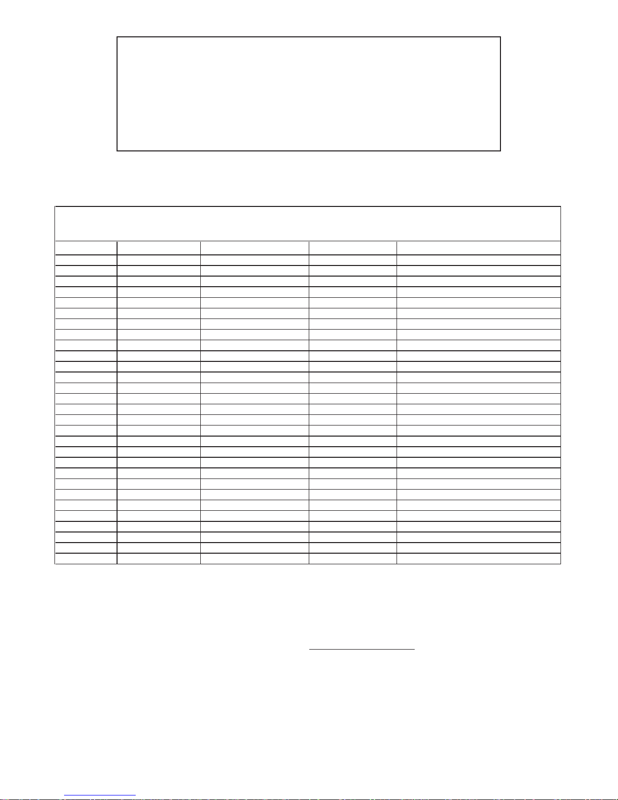
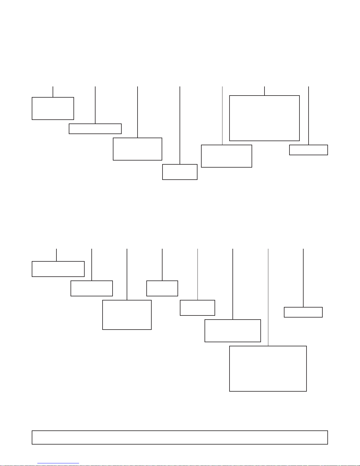
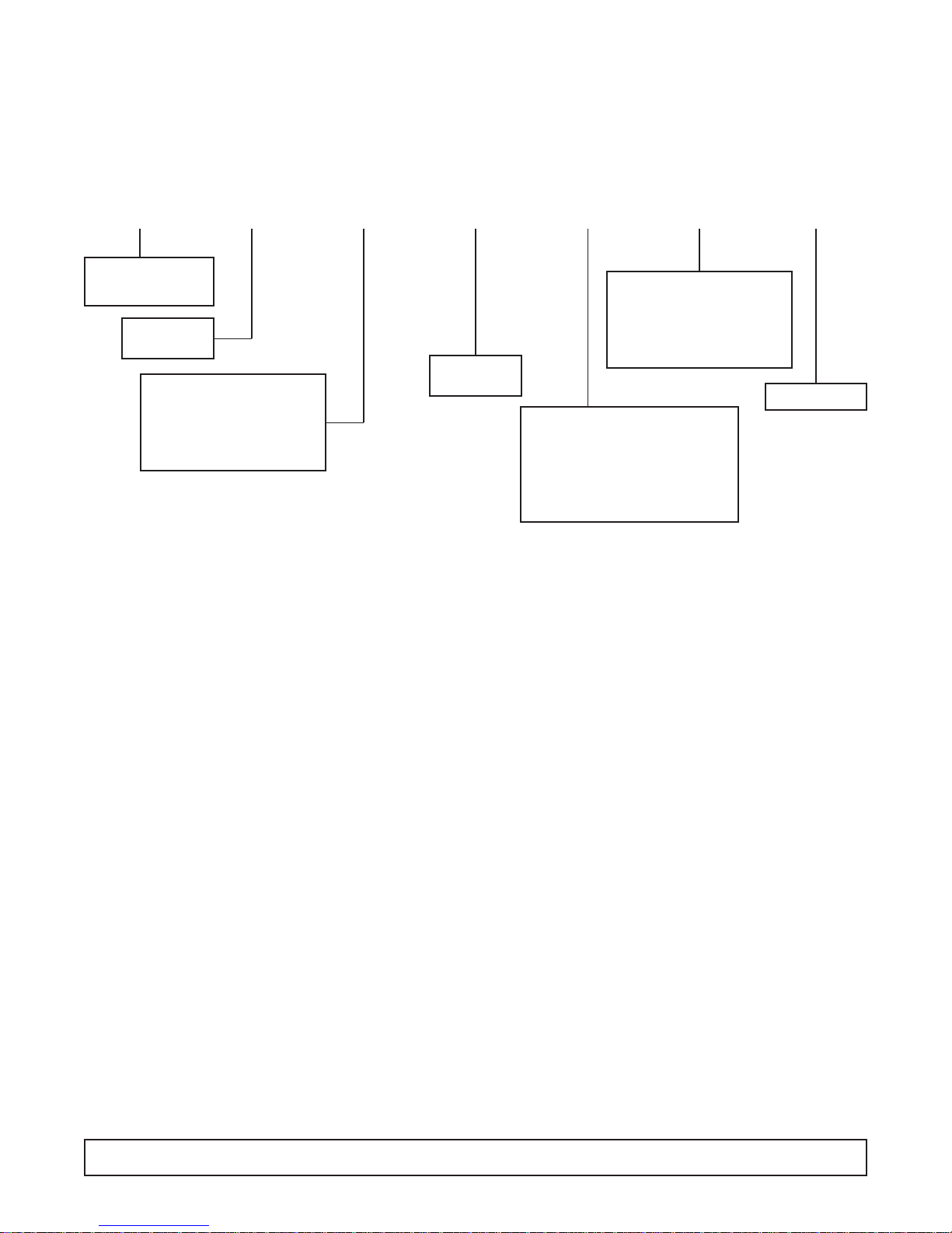
WIRING DIAGRAM REFERENCE
18 WIRING DIAGRAM REFERENCE
CONTROL
PANEL
LIGHTS,
FLUORESCENT SOLENOID
RECEPTACLE
BOX / LIGHT EVAPORATOR
INCAND LIGHT,
RACEWAY
ANTI-SWEAT
HTR, RACEWAY
WIRING DIAGRAM REFERENCE
DOOR SWITCH,
RACEWAY
MODELS LADDER COMPRESSOR ELECT BOX
BT30RF- EXPR 26-0983-00
BT30RF-FMS 00-0428-00
BT30RG-4.1 00-0052-00 00-0137-00 00-0056-00 00-0050-01 00-0067-01 00-0058-01/02
BT30RGCH-4.1 00-0052-00 00-0137-00 00-0056-00 00-0059-00 00-0050-01 00-0067-01 00-0058-01/02
BT30RS-4.1 00-0052-00 00-0071-00 00-0056-00 00-0061-01 00-0061-05 00-0050-01 00-0058-01
BT30RSFMS-4.1 00-0055-00 00-0071-00 00-0057-00 00-0050-04 00-0058-01
BT50RG-4.1 00-0052-00 00-0084-00 00-0056-00 00-0061-04 00-0050-01 00-0067-02 00-0058-01/02
BT50RGCH-4.1 00-0052-00 00-0084-00 00-0056-00 00-0061-04 00-0059-00 00-0050-01 00-0067-02 00-0058-01/02
BT50RS-4.1 00-0052-00 00-0071-00 00-0056-00 00-0061-02 00-0061-04 00-0061-05 00-0050-01 00-0058-01
BT50RSFMS-4.1 00-0055-00 00-0071-00 00-0057-00 00-0050-04 00-0058-01
BT80RG-4.1 00-0052-00 00-0084-00 00-0056-00 00-0061-04 00-0050-01 00-0067-03 00-0058-01/02
ST260RIR-4.1 00-0053-00 00-0071-00 00-0064-00 00-0061-01 00-0061-04 00-0065-00 00-0050-03 00-0065-00 00-0017-12
ST30RGBB-4.1 00-0052-00 00-0137-00 00-0056-00 00-0061-01 00-0050-01 00-0067-01 00-0017-10
ST50RGBB-4.1 00-0052-00 00-0084-00 00-0056-00 00-0061-04 00-0050-01 00-0067-02 00-0017-10
T30MGP-4.1 00-0052-00 00-0137-00 00-0056-00 00-0050-01 00-0067-01
T30MSP-4.1 00-0052-00 00-0071-00 00-0056-00 00-0050-01
T50MGP-4.1 00-0052-00 00-0084-00 00-0056-00 00-0061-04 00-0050-01 00-0067-02
T50MGPR-4.1 00-0052-00 00-0056-00 00-0061-04 00-0050-01 00-0067-02 00-0060-00
T50MSP-4.1 00-0052-00 00-0071-00 00-0056-00 00-0061-04 00-0050-01
T80MGP-4.1 00-0052-00 00-0084-00 00-0056-00 00-0061-04 00-0050-01 00-0067-03
T80MGPR-4.1 00-0052-00 00-0056-00 00-0061-04 00-0050-01 00-0067-03 00-0060-00
UMG30BS-4.1 00-0052-00 00-0137-00 00-0056-00 00-0050-01 00-0067-01
UMG50BS-4.1 00-0052-00 00-0084-00 00-0056-00 00-0061-04 00-0050-01 00-0067-02
UMG50RS-4.1 00-0052-00 00-0056-00 00-0061-04 00-0050-01 00-0067-02 00-0060-00
UMG80BS-4.1 00-0052-00 00-0084-00 00-0056-00 00-0061-04 00-0050-01 00-0067-03
UMG80RS-4.1 00-0052-00 00-0056-00 00-0061-04 00-0050-01 00-0067-03 00-0060-00
UMH30BS-4.1 00-0052-00 00-0137-00 00-0056-00 00-0050-01 00-0067-01
UMH50BS-4.1 00-0052-00 00-0084-00 00-0056-00 00-0061-04 00-0050-01 00-0067-02
UMH80BS-4.1 00-0052-00 00-0084-00 00-0056-00 00-0061-04 00-0050-01 00-0067-03
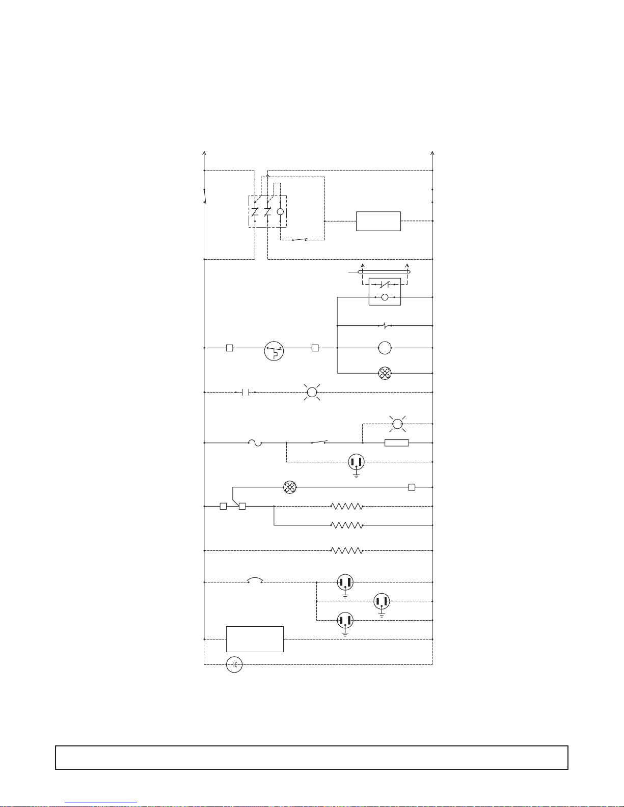
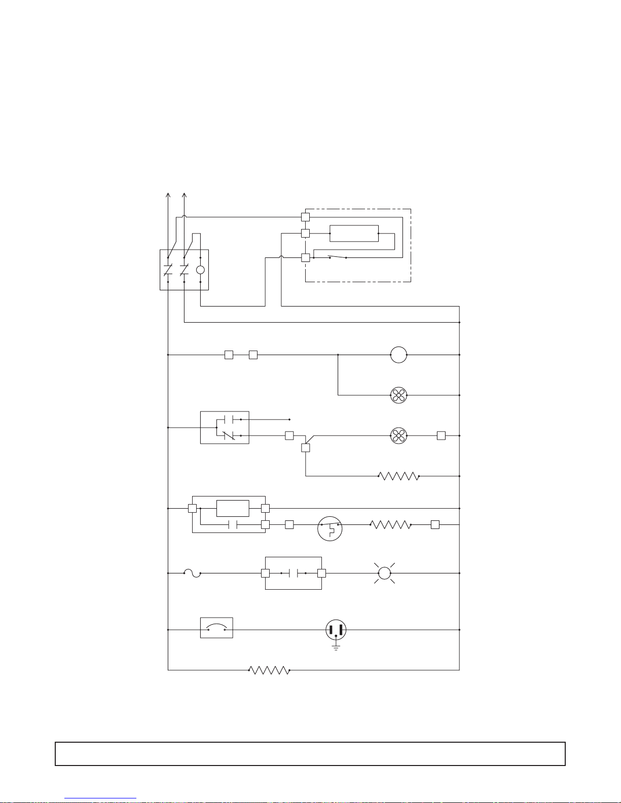
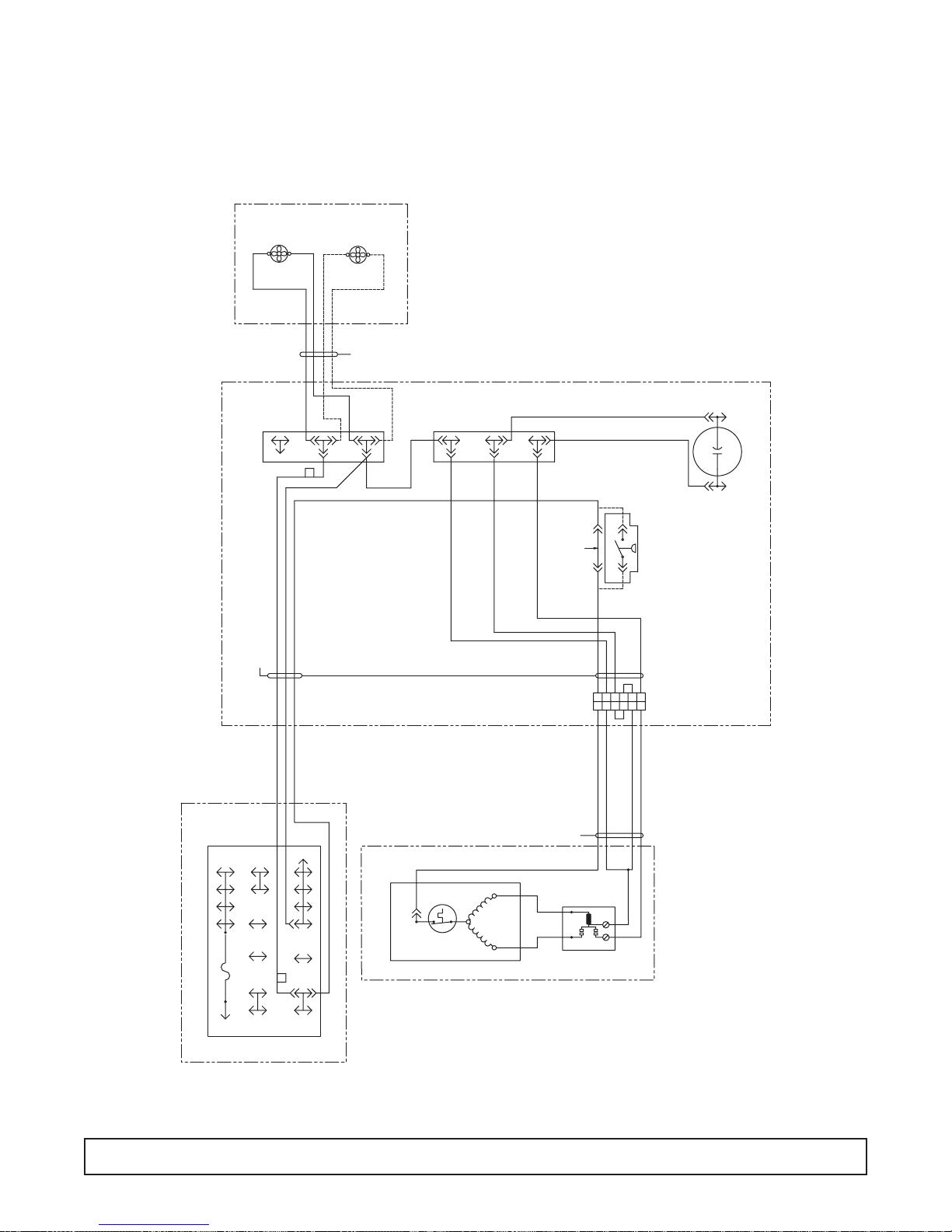
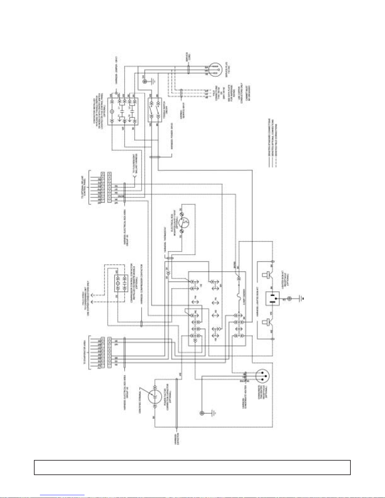
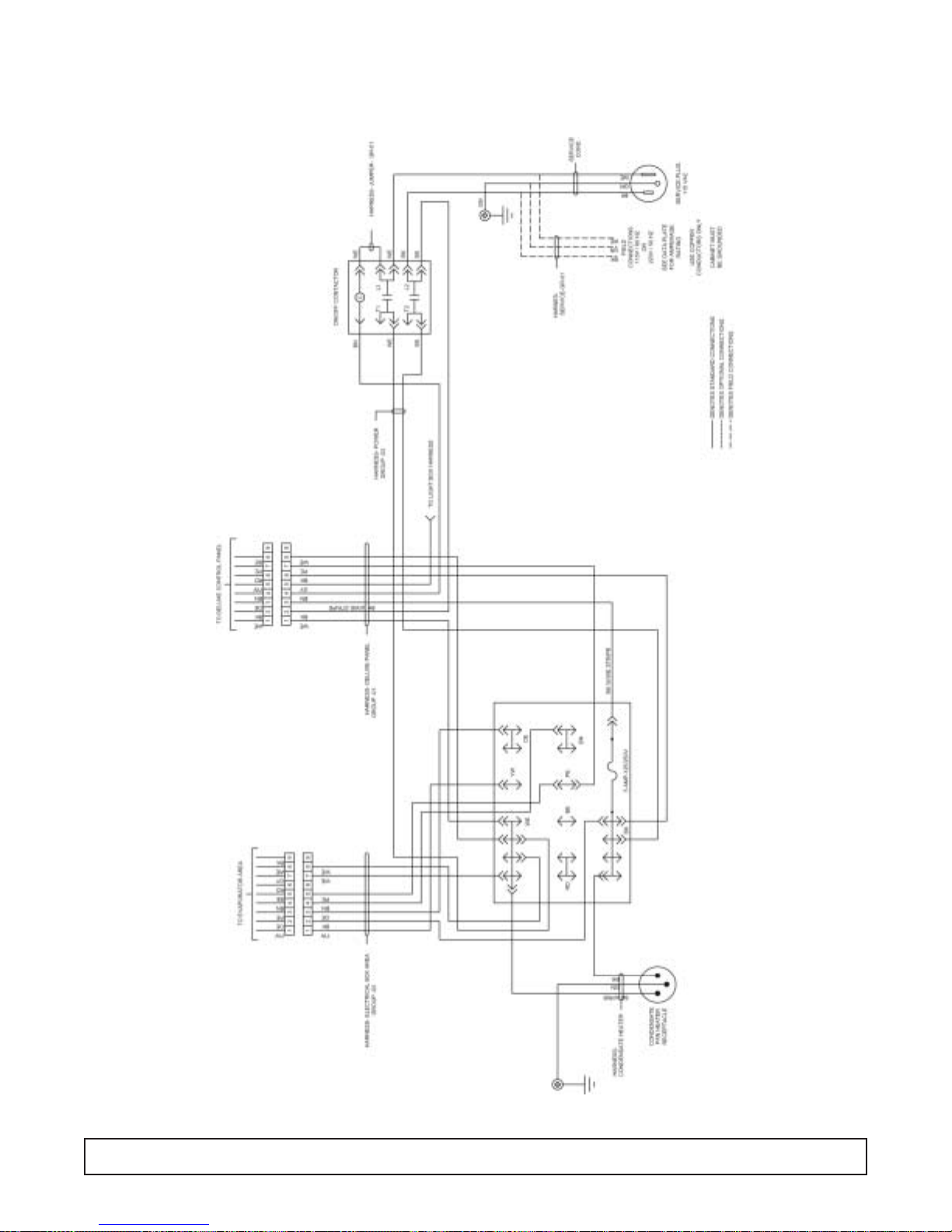
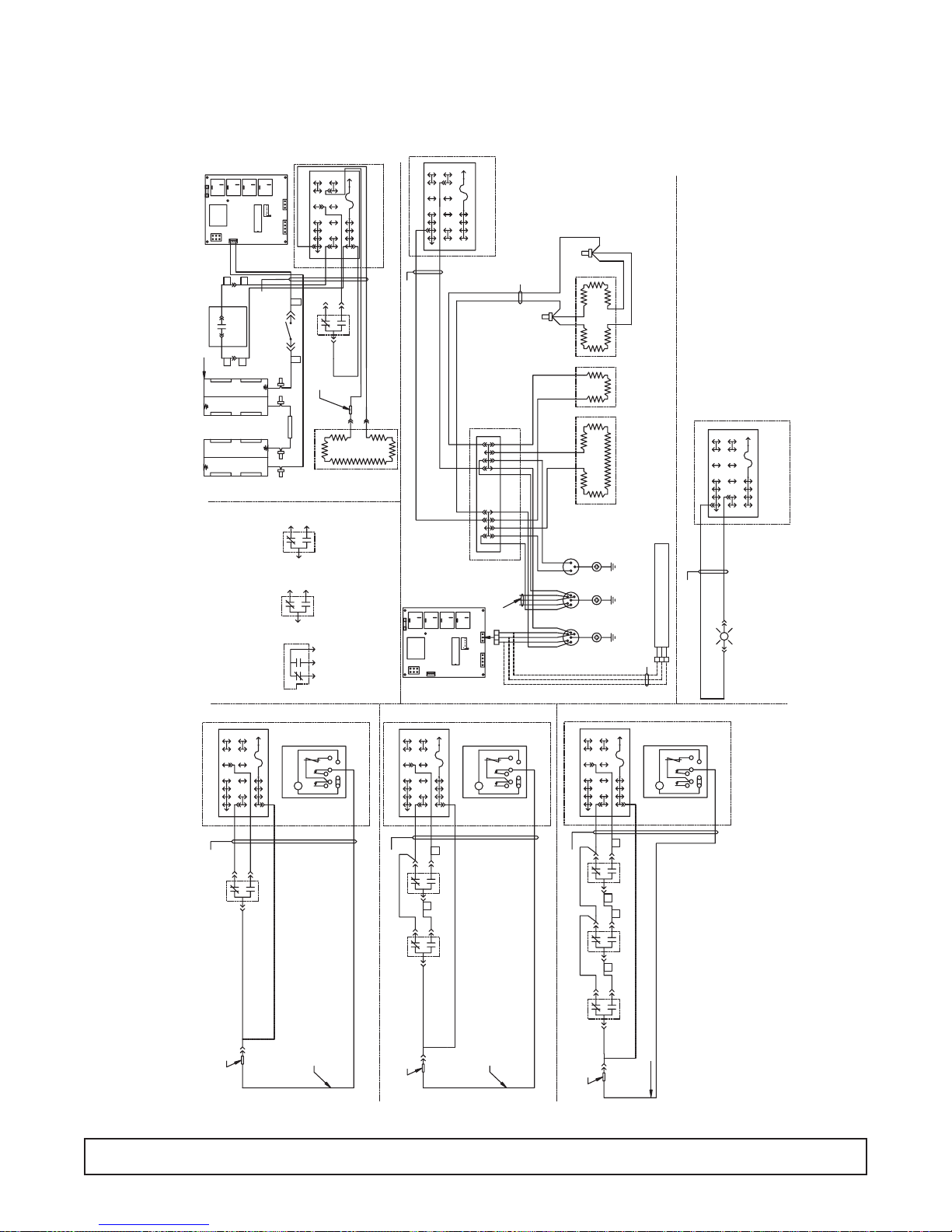
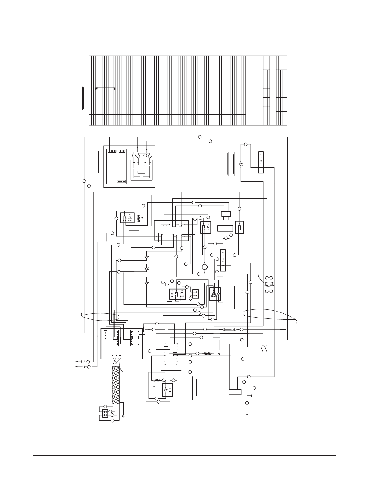
LADDER WIRING DIAGRAM – 00-0052-00
WIRING DIAGRAM 19
MED TEMP
115V, 60 HZ
220V, 50 HZ
ALL CONTROLS SHOWN IN OPERATING MODE
L1 N
CABINET MUST BE GROUNDED
DENOTES PIN NUMBER OF 9 PIN CONNECTOR
*
BK
SEE DATA PLATE FOR AMPERAGE RATING
USE COPPER CONDUCTORS ONLY
WE
C
M
OPTIONAL
INDICATOR
BALLAST/SLIGHT SWITCH
WE
L
DPSTDPST
ON/OFF
SWITCH
WE
POWER POWER
ON/OFF
SWITCH
BK OE
BK RD WE
OPTIONAL DOOR
(MODELS WITH FLUORESCENT LIGHTING SYSTEM)
BK
BK
WE
WE
OPTIONAL
ON/OFF
SWITCH
C
AND
CONTACTOR
BK
BN
WE
FIELD WIRED TO CONDENSING UNIT
USE COPPER CONDUCTORS ONLY
CAVITY T'STAT
OE OE OE WE
2
CNC
SWITCH/S
OPTIONAL INCANDESCENT
FUSE
INTERIOR LIGHT
OR DOOR AJAR
INDICATOR
BK/WE
BK
BK
COMP. CONTROL CONTACTOR
LIQUID LINE SOLENOID VALVE
3
(SELF CONTAINED MODELS)
L
(SELF CONTAINED MODELS)
BK WE
OPTIONAL DELUXE
CONTROL PANEL
BLOOD BANK MODELS
OE
(REMOTE MODELS)
OE
(REMOTE MODELS)
COMPRESSOR
OE WE
COND FAN/S
GY
RECEPTACLEOPTIONAL LIGHTED SIGN KIT
GY
WE
WE
WE
BK
94
BK
OPTIONAL CIRCUIT BREAKER
BK WE
OPTIONAL POWER
FACTOR CORRECTION
CAPACITOR 55 MFD
BN WE WE
BN
BK BK WE
EVAP FAN/S
BN
OPTIONAL RECEPTACLES
OPTIONAL
CHART RECORDER
WEBK
BN
OPTIONAL HEATED GLASS DOOR/S
BN WE
MULLION HEATERS/S
(SOLID 2 & 3 DOOR MODELS)
BK BK W/RIB
CONDENSATE PAN HEATER
OPTIONAL
BK
BK
WE
WE
WE
WE
BK
P/N 00-0052-00 Rev A
8
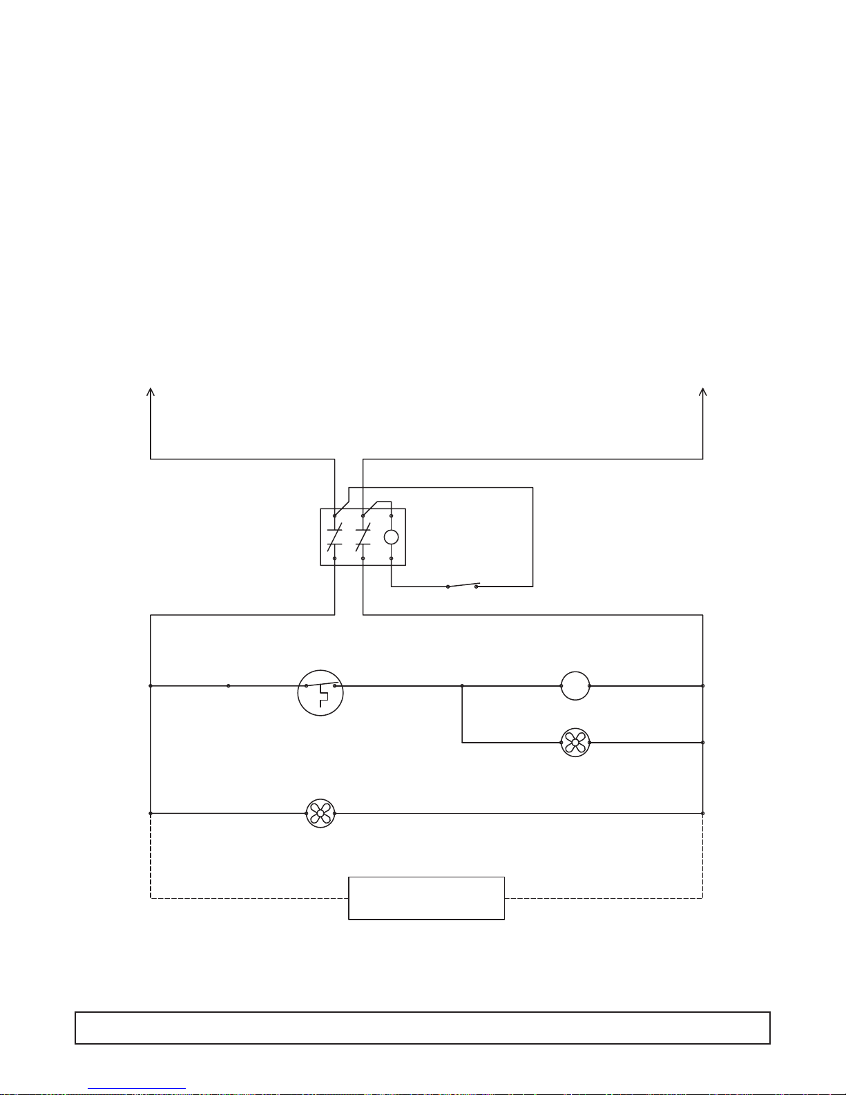
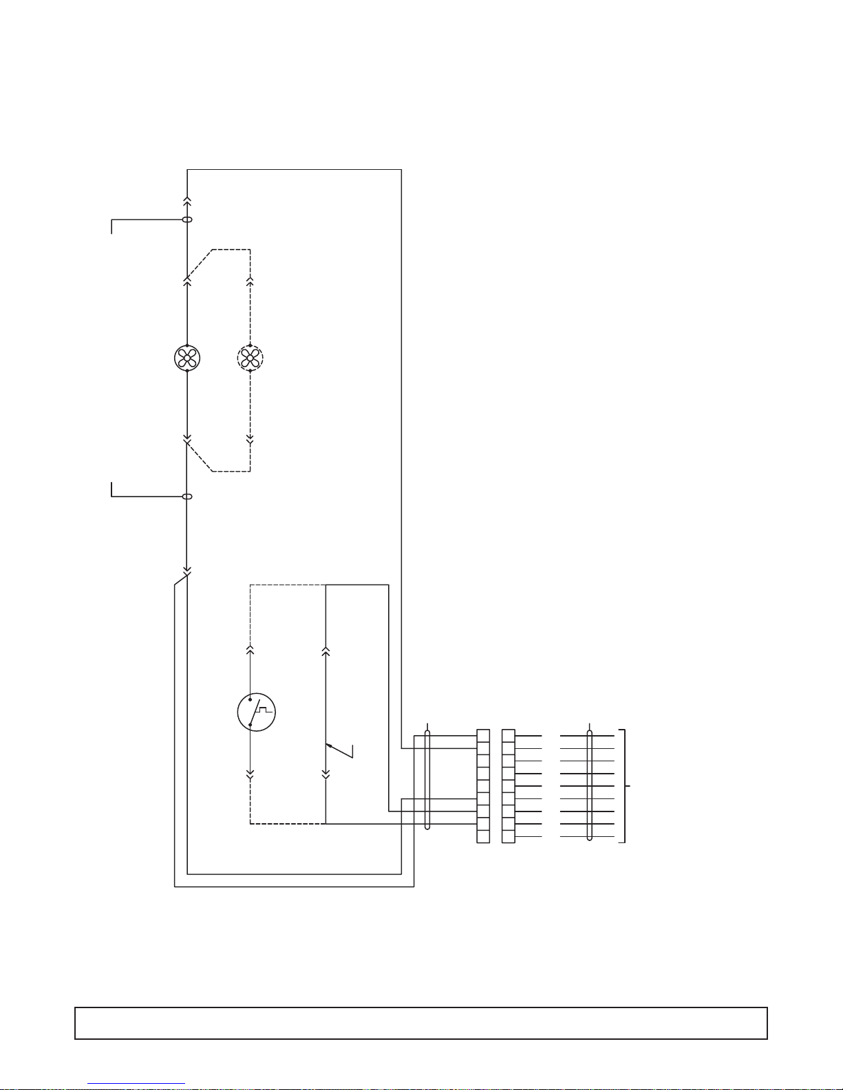
LADDER WIRING DIAGRAM – 00-0053-00
20 WIRING DIAGRAM
INCUBATOR
115V, 60 HZ
220V, 50 HZ
ALL CONTROLS SHOWN IN OPERATING MODE
CABINET MUST BE GROUNDED
*
DENOTES PIN NUMBER OF 9 PIN CONNECTOR
L1 N
BK
WE
BK
WE
WE
ON/OFF
C
CONTACTOR
BK
BN
WE
BK
DOOR SWITCH
BK OE
OE
23
NC
NO
SEE DATA PLATE FOR AMPERAGE RATING
USE COPPER CONDUCTORS ONLY
BK
2
WEBKWE
1
BN
4
RD
YW
YW BN
1
4EVAP FAN
BN
BN
ON/OFF
SWITCH
CONTROL PANEL
TEMPERATURE
MONITOR
BK
DELUXE
PERIMETER HEATER
BN
OE WE
M
COMPRESSOR
CONDENSOR FAN
BN WE
BN WE
WEOE
8
BK WE
RD
DELUXE
CONTROL PANEL
FUSE
BK
CIRCUIT BREAKER
CONDENSATE PAN HEATER
BE
TEMP
CONTROL
BK/WE OE
86
PE
PE
7
LIGHT SWITCH
CONTROL PANEL
BK
BK BK W/RIB
RD BK
5
HIGH TEMP SAFETY
DELUXE
RECEPTACLE
T'STAT
GYYW
53
INTERIOR LIGHT
BK WE
CAL-ROD
INCANDESCENT
P/N 00-0053-00
GY WE
7
L
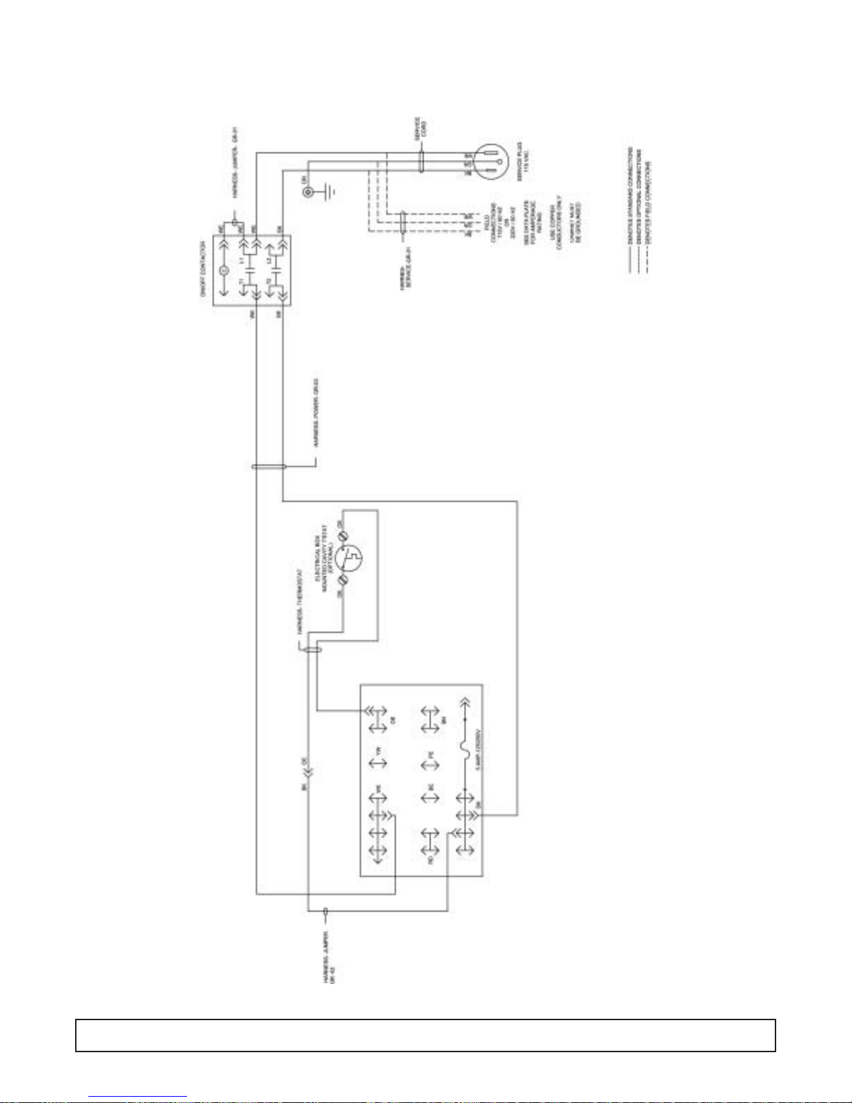
LADDER WIRING DIAGRAM – 00-0055-00
WIRING DIAGRAM 21
MEDIUM TEMP SCIENTIFIC
115V, 60 HZ
220V, 50 HZ
ALL CONTROLS SHOWN IN OPERATING MODE.
SEE DATA PLATE FOR AMPERAGE RATING
USE COPPER CONDUCTORS ONLY
CABINET MUST BE GROUNDED
L1 N
BK
BK
OE
BK WE
CAVITY
T'STAT
BK
BK W/RIB
OE
BK
WE
ON/OFF
C
& CONTACTOR
BN
SWITCH
BK
COMPRESSOR
CONDENSOR FAN/S
WEOE
M
OE WE
WE
EVAPORATOR FAN/S
OPTIONAL
CHART RECORDER
WEBK
P/N 00-0055-00
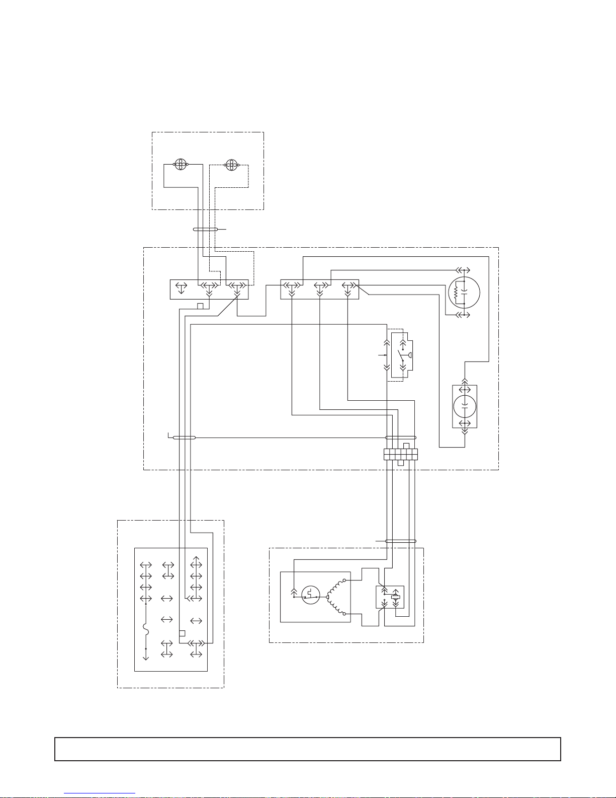
COMPRESSOR WIRING DIAGRAM – 00-0071-00
22 WIRING DIAGRAM
FAN #1
CONDENSOR
F
D
NAL BOAR
I
TERM
START BOX ASSY
220V, 50 HZ
115V, 60 HZ
GR-01
HARNESS- START
FAN #2
(OPTIONAL)
CONDENSOR
F
CONDENSOR FAN ASSY
OPTIONAL CONNECTIONS SHOWN WITH DASHED LINES.
1) STANDARD CONNECTIONS SHOWN WITH SOLID LINES;
(NORMAL OPERATION)
2) F FORWARD ROTATION CONDENSOR FAN
NOTES-
FAN LEADS
CONDENSOR
E
W
WE
R
O
OR
K
K
K
B
BK
F
E
O
W
E
OE
B
B
WE
K
B
K
B
K
B
K
BE
RD
WE
B
JUMPER (REMOVE WHEN
INSTALLING PRESSURE SWITCH)
OE
6
(OPTIONAL)
PRESSURE SWITCH
11223344556
START CAP
K
B
RUN CAP
K
B
RD
BK
BEPE
ELECTRICAL BOX ASSY
5 AMP-125/250V
BN
WEYW
F
OE
TERMINAL BLOCK
COMPRESSOR
C
O.L.
AMERICOLD COMPRESSOR ASSY
HARNESS- COMPRESSOR GR-01
OE
RELAY
PIN
WE
2
1
3
4
RD
BE
PIN
R
S
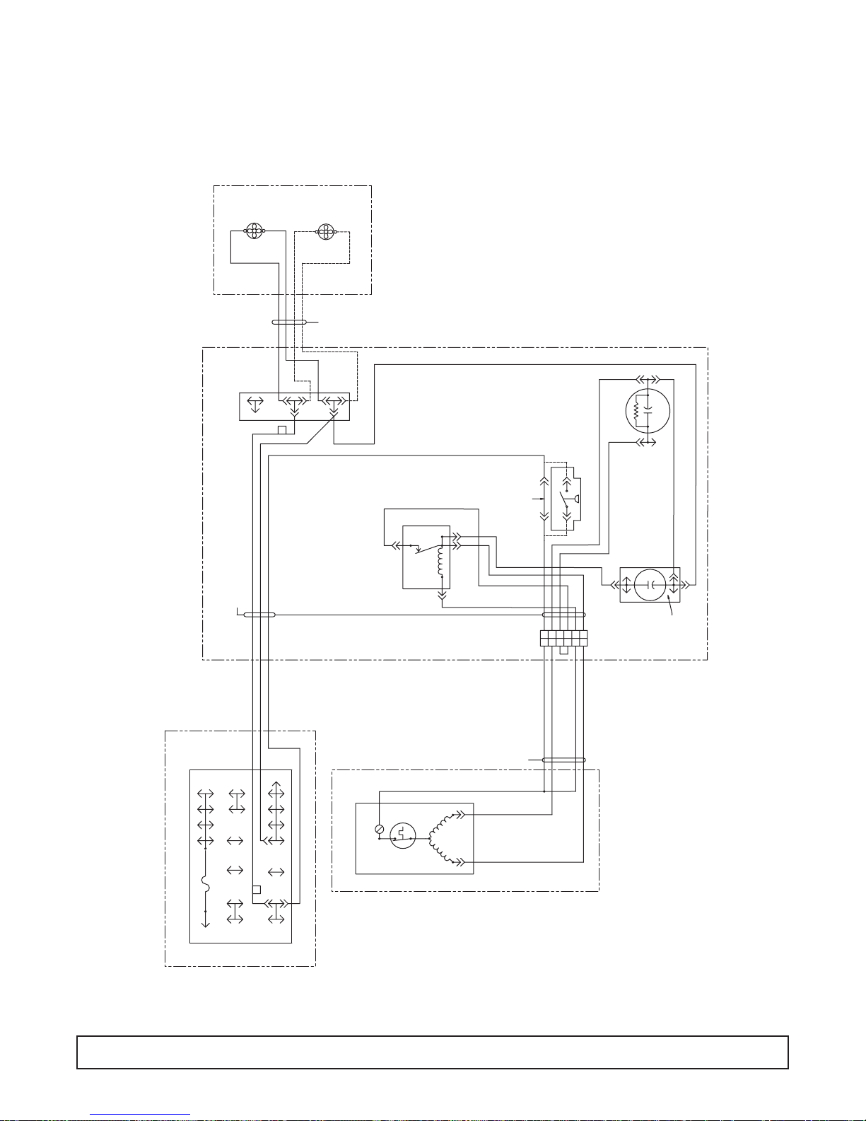
COMPRESSOR WIRING DIAGRAM – 00-0084-00
WIRING DIAGRAM 23
FAN #1
CONDENSOR
F
D
R
TERMINAL BOA
START BOX ASSY
220V, 50 HZ
115V, 60 HZ
GR-02
HARNESS- START
FAN #2
(OPTIONAL)
CONDENSOR
F
CONDENSOR FAN ASSY
FAN LEADS
CONDENSOR
E
WE
W
R
OR
O
K
K
K
B
BK
F
E
O
E
W
OE
B
B
WE
Z
1
RELAY
5
OPTIONAL CONNECTIONS SHOWN WITH DASHED LINES.
1) STANDARD CONNECTIONS SHOWN WITH SOLID LINES;
(NORMAL OPERATION)
2) F FORWARD ROTATION CONDENSOR FAN
NOTES-
JUMPER (REMOVE WHEN
INSTALLING PRESSURE SWITCH)
OE
BN
OE
YW
WE
6
(OPTIONAL)
PRESSURE SWITCH
BE
RD
11223344556
WE
START CAP
BN
WE
WE
BE
AL
IED
RUN CAP
TERMIN
IDENTIF
RD
BK
BEPE
WEYW
ELECTRICAL BOX ASSY
5 AMP-125/250V
F
OE
BN
TERMINAL BLOCK
COMPRESSOR
COPELAND AST54
COMPRESSOR ASSY
115V, 60 HZ
220V, 50 HZ
HARNESS- COMPRESSOR GR-05
OE
R
C
O.L.
S
WE
BE
COMPRESSOR WIRING DIAGRAM – 00-0137-00
24 WIRING DIAGRAM
FAN #1
CONDENSOR
F
D
TERMINAL BOAR
START BOX ASSY
220V, 50 HZ
115V, 60 HZ
GR-01
HARNESS- START
FAN #2
(OPTIONAL)
CONDENSOR
F
CONDENSOR FAN ASSY
OPTIONAL CONNECTIONS SHOWN WITH DASHED LINES.
1) STANDARD CONNECTIONS SHOWN WITH SOLID LINES;
(NORMAL OPERATION)
2) F FORWARD ROTATION CONDENSOR FAN
NOTES-
FAN LEADS
CONDENSOR
E
W
WE
R
R
O
O
K
K
K
B
BK
F
E
O
W
E
OE
B
B
WE
WE
K
B
K
B
BE
RD
(OPTIONAL)
PRESSURE SWITCH
JUMPER (REMOVE WHEN
INSTALLING PRESSURE SWITCH)
OE
START CAP
RD
BK
BEPE
ELECTRICAL BOX ASSY
5 AMP-125/250V
BN
6
11223344556
115V, 60 HZ
220V, 50 HZ
RD
WE
HARNESS- COMPRESSOR GR-01
OE
R
2
WEYW
F
TERMINAL BLOCK
OE
COMPRESSOR
COPELAND ASE24
COMPRESSOR ASSY
C
O.L.
S
M
S
1
RELAY
WE
BE
ELECTRICAL BOX WIRING DIAGRAM – 00-0056-00
WIRING DIAGRAM 25
ELECTRICAL BOX WIRING DIAGRAM – 00-0057-00
26 WIRING DIAGRAM
ELECTRICAL BOX WIRING DIAGRAM – 00-0064-00
WIRING DIAGRAM 27
RACEWAY WIRING DIAGRAM – 00-0061-*
28 WIRING DIAGRAM
OE
(OPTIONAL)
34
1
2
6
5
BN
YW
5 AMP-125/250V
PE
WE
BE
BK
RD
ELECTRICAL BOX ASSY
HARNESS- SHORT MULLION HEATER
WE
WE
WE
BN
BK
BK
BN
BN
BN
BN
BN
BN
RACEWAY
TERMINAL BLOCK
WE
WE
WE
WE
WE
WE
CUT
WIRES
RD
3
GN
BK
DISPLAY
12
1 2 3 4 5 6 7 8
N
O
1 324 213
BN
RD
GN
BK
WE
BN
WE
(OPTIONAL)
GLASS HEAT
DOOR RECEPTACLE
GN
GN
GN
3
2
1
564
03
RD
PUSHBUTTON
BK
BATTERY BACKUP
02
03
SWITCH
02
DISPLAY
1 2 3 4 5 6 7 8
O
N
1423 123
TERMINAL BLOCK
01
GROUP- 04
01
HARNESS- DOOR SWITCH
BK
-
+
RD
RD
RECTIFIER
-
-
BK
BK
+
+
RD
3
1
2
CARLINGSWITCH
1
3
2
DOOR SWITCH TERMINAL NUMBERS
McGILL
12
3
ARCOELECTRIC
OE
YW
WE
RD
BK
BLACK TAPE
C
NO
NC
(RED)
BE
RD
BNPE
5 AMP-125/250V
BK
YW
DOOR SWITCH
BN
BK
ELECTRICAL BOX ASSY
HARNESS- ANTI-SWEAT HEATER
UNDER COUNTER MODELS
WE
*GR-06
WE
PERIMETER HEATER
"PULSE"
ALL VERTICAL MODELS
OPTIONAL HEATED DOOR
OPTIONAL ANTI-SWEAT HTRS
CABINETS ONLY)
SHORT MULLION HEATER
(QUAD-DOOR HARDENING
(OPTIONAL)
MULLION HEATER
2 & 3 DOOR MODELS
(OPTIONAL)
PERIMETER HEATER
MODELS
NON-PULSE
PULSE
MODELS
W/0 DISPLAY
PULSE DISPLAY IN SOLID DR FRT PANEL
PULSE
DOOR DOOR
MODELS
W/DISPLAY
321
HARNESS- DISPLAY
*GR-04
OE
YW
TERMINAL BLOCK
WE
OR
L
WE RD
HARNESS- INCANDESCENT LIGHT
HARNESS- HARDENING CABINET LIGHT
BN
5 AMP-125/250V
PE
BE
BK
RD
ELECTRICAL BOX ASSY
*GR-05
(OPTIONAL)
INCANDESCENT LIGHT
ALL SOLID DOOR VERTICAL MODELS
OPTIONAL INCANDESCENT INTERIOR LIGHT
BN
OE
YW
5 AMP-125/250V
PE BN
TIME CLOCK
BE
TERMINAL BLOCK
BK
WE
RD
RD
YW
DOOR 1
BK
HARNESS- DOOR SWITCH GROUP -01
LOW TEMP "PULSE" MODELS
MED. TEMP & INCUBATOR MODELS
BLACK TAPE
OE
X34
OE
12 N
T
YW
TERMINAL BLOCK
ELECTRICAL BOX ASSY
RD
RD
HARNESS- DOOR SWITCH GROUP -02
VERTICAL MODELS
LOW TEMP MODELS
1 DOOR
OPTIONAL DOOR SWITCH
REMOVE "OE" WIRE ON MED. TEMP & INCUBATOR MODELS
BLACK TAPE
*GR-01
OE
WE
BK
OE
BN
PE
BE
RD
NO
YW
C
YW
5 AMP-125/250V
TIME CLOCK
T
BK
DOOR 2
DOOR 1
MED. TEMP MODELS
LOW TEMP "PULSE" MODELS
REMOVE "OE" WIRE ON MED. TEMP MODELS
X
N
43
2
1
OE
LOW TEMP MODELS
ELECTRICAL BOX ASSY
VERTICAL MODELS
2 DOOR
*GR-02
OE
YW
5 AMP-125/250V
PE
BE
TERMINAL BLOCK
BK
WE
RD
NO
RD
YW
DOOR 3
C
RD
YW
NO
HARNESS- DOOR SWITCH GROUP -03
DOOR 2
C
RD
YW
DOOR 1
OPTIONAL DOOR SWITCHES
BK
BLACK TAPE
OE
X
N
34
TIME CLOCK
12
T
OPTIONAL DOOR SWITCHES
LOW TEMP MODELS
VERTICAL MODELS
LOW TEMP "PULSE" MODELS
MED. TEMP MODELS
3 DOOR
REMOVE "OE" WIRE ON MED. TEMP MODELS
*GR-03
OE
ELECTRICAL BOX ASSY
EVAPORATOR WIRING DIAGRAM – 00-0050-*
WIRING DIAGRAM 29
WEWE
BKBK
1 FAN
EVAP FAN/S
GROUP -01; 1 DOOR
GROUP -02; 2 DOOR/3 DOOR
HARNESS- EVAPORATOR FAN EXTENSION
BN
BN
BN
BK
MOUNTED
CAVITY T'STAT
EVAPORATOR AREA
BN BK BK WE
OE
SPADESPADE
OE
2 FANS
USE WITH
CAVITY
T' STAT
REMOTE
MOUNTED
OE
(REMOVE JUMPER WHEN
INSTALLING THERMOSTAT)
OE OE
GROUP -02
HARNESS- EVAPORATOR AREA
BK
WE
BN
OE
OE
HARNESS- MAIN CABINET
98
123456789
1432765
BK
WE
GY
RD
BE
BN
PE
OE
YW
(EXIT EVAPORATOR AREA)
TO ELECTRICAL BOX
*GR.-01
MED. TEMP MODELS
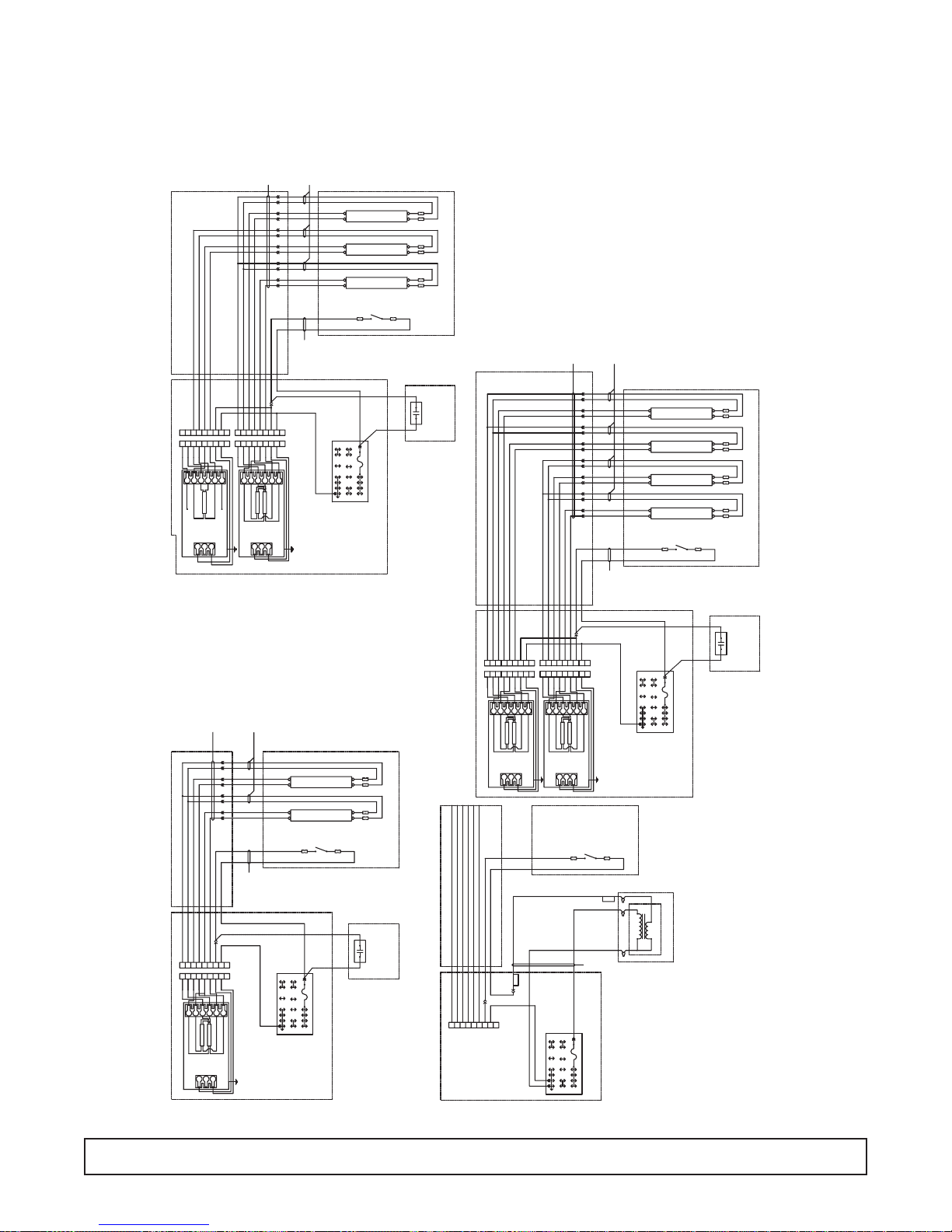
FLUORESCENT LIGHT WIRING DIAGRAM – 00-0067-*
30 WIRING DIAGRAM
LAMP FIXTURE EXTENSION
FLOURESCENT LIGHT, GR-02
HARNESS-
HARNESS-
YW
YW
YW
RACEWAY
BE
BE
BE
BE
RD
RD
RD
YW
YW
YWYW
WE
WE
YW
YW
WE
WE
YW
WEWERD
BKBK GY
HARNESS-
LIGHT SWITCH
(OPTIONAL)
LIGHT SWITCH
WE
WE
WE
CAVITY SIDEWALL
BK/WE
YWYWWE
BEBEWE
YWYWWE
CAVITY LIGHT CHANNELS
LAMP FIXTURE EXTENSION
FLOURESCENT LIGHT, GR-03
HARNESS-
HARNESS-
BE
BE
YW
YW
RD
ONE LAMP WIRING
CAP
BALLAST
RACEWAY
BE
YW
YW
BE
YW
YW
L2
BALLAST
GY
BE
GY
RD
BK
RD
L1BEC
RD
WHT
HARNESS-
WE
WE
L2
YW
CAP
FLOURESCENT LIGHT, GR-01
YW
YW
BE
BE
YW
YWYW
RD
BE
RD
GY
RDRD
WE
YW
YW
BK
BE
BE
RD
WE
YW
YW
L2
L1YWC
C
L1BEL2
RD
BE
RD
YW
TWO LAMP WIRING
LAMP 2
LAMP 1
LINE
BALLAST
WHT
BLK
HARNESS-
LAMP FIXTURE EXTENSION
YW
YW
WE
WE
YW
WEWERD
OE
BN
PE
YW
BE
WE
RD
(OPTIONAL)
LIGHT SWITCH
CAVITY SIDEWALL
BK GYBKBK/WE
5 AMP-125/250V
BK
WE
WEWEYW
ELECTRICAL BOX
YW WE
YW
YW
CAVITY LIGHT CHANNELS
BK/WE GY
BE
BE
RD RD
C
L1YWL2
BE
LAMP 1
LINE
BLK
(2) DOOR CABINET- (2- BALLAST / 3- BULBS) *GR-02
ROCKER OR
PUSHBUTTON
LIGHT SWITCH
OPTIONAL
CONTROL PANEL
RACEWAY
BE
BE
RDRD
RD
GY
YW
YW
YW
YW
L2
TWO LAMP WIRING
BALLAST
YW
WE
BK
BE
BE
RD
YW
WE
L2
L1YWC
C
RD
BE
RD
YWL1BE
LAMP 1
LAMP 2
LINE
WHT
BLK
RACEWAY
HARNESS-
LIGHT SWITCH
GY
ELECTRICAL BOX
BK/WE GY
ROCKER OR
PUSHBUTTON
LIGHT SWITCH
OPTIONAL
CONTROL PANEL
(1) DOOR CABINET- (1- BALLAST / 2- BULBS) *GR-01
BE
BE
YW
YW
SEC
RD
RD
GY GY
WE
BE
RD
RD
GY
BE
BK
RD
RD
WE WE
L2
L1YWC
C
RD
BE
RD
YWL1BE
TWO LAMP WIRING
LAMP 1
LAMP 2
LINE
WHT
BLK
OE
BN
5 AMP-125/250V
YW
BE PE
BK
WE
RD
YW
YW
BALLAST
YW YW
YW YW
WE BE
BE
YW YW
YW YW
WE
RD
WE
RD
YW YW
YW YW
WE
BE
WE
BE
YW YW
YW YW
WE
RD
WE
RD
BKBK GY
HARNESS-
LIGHT SWITCH
GY
BE
BE
GY
RD
RD
WE
BK
BE
BE
RD
RD
WE
L2
CCL2BEL1
YW
YWL1BE
RD
RD
TWO LAMP WIRING
LAMP 1
LAMP 2
LINE
BLK
WHT
BK/WE
BK
WE
BNPE
5 AMP-125/250V
YW OE
BE
BK
WE
RD
ELECTRICAL BOX
SEC
(OPTIONAL)
LIGHT SWITCH
HARNESS-
CAVITY SIDEWALL
BK/WE BK BK GY
CAVITY LIGHT CHANNELS
INPUT/PRIMARY
BALLAST TRANS.
OE
BN
5 AMP-125/250V
PE
YW
BE
BK
WE
RD
ELECTRICAL BOX
EXPORT
OUTPUT/SECONDARY
BALLAST TRANFORMER
TYPICAL EXPORT TRANSFORMER CONNECTIONS *GR-04
(OPTIONAL)
LIGHT SWITCH
WE WE
WEYW
WEYW
WEYW
WE
WEYW
CAVITY SIDEWALL
BK/WE
GY
BK/WE
YWYWWE
YW WE
ROCKER OR
PUSHBUTTON
CAVITY LIGHT CHANNELS
LIGHT SWITCH
OPTIONAL
CONTROL PANEL
(3) DOOR CABINET- (2- BALLAST / 4- BULBS) *GR-03

SOLENOID WIRING DIAGRAM – 00-0060-00
WIRING DIAGRAM 31
OE
YW
WE
HARNESS- SOLENOID VALVE
BN
PE
5 AMP-125/250V
BE
BK
RD
BK BK OE
WE
MODELS
LIQUID LINE
SOLENOID VALVE
INSTALL ON REMOTE

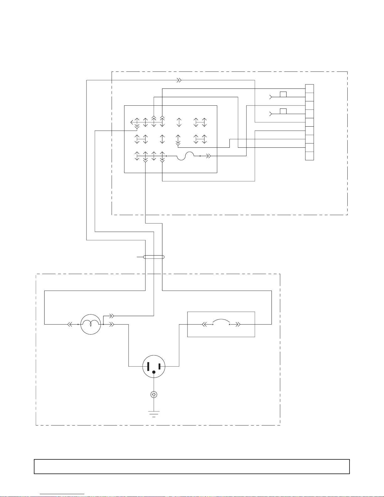
RECEPTACLE BOX/LIGHT WIRING DIAGRAM – 00-0059-00
32 WIRING DIAGRAM
PE BN
YW OE
5 AMP-125/250V
ELECTRICAL BOX
TERMINAL BLOCK
WE
RD BE
BK
BKWE
BK
TERMINAL BLOCK
BK
WE
WE
BKBKBKWE WE WE
GN
GN
WE BK
GN
HARNESS- RECEPTACLE BOX SUPPLY
CIRCUIT BREAKER
BK BK
RECEPTACLE BOX- BACK OF CAVITY
RECEPTACLE BOX/LIGHT WIRING DIAGRAM – 00-0065-00
WIRING DIAGRAM 33
GY GY
WE
L
C
WE
RD
BK
BE
YW OE
PE
BN
BK/WE
5 AMP-125/250V
TERMINAL BLOCK
ELECTRICAL BOX
1
BK
2
BK/WE
3
BN
4
GY
5
BK
6
PE
7
WE
8
9
DELUXE CONTROL
PANEL CONNECTOR
HARNESS- LIGHT BOX SUPPLY
INCANDESCENT LIGHT
WE
WEGY BK BK
CIRCUIT BREAKER
GN
LIGHT BOX- BACK OF CAVITY
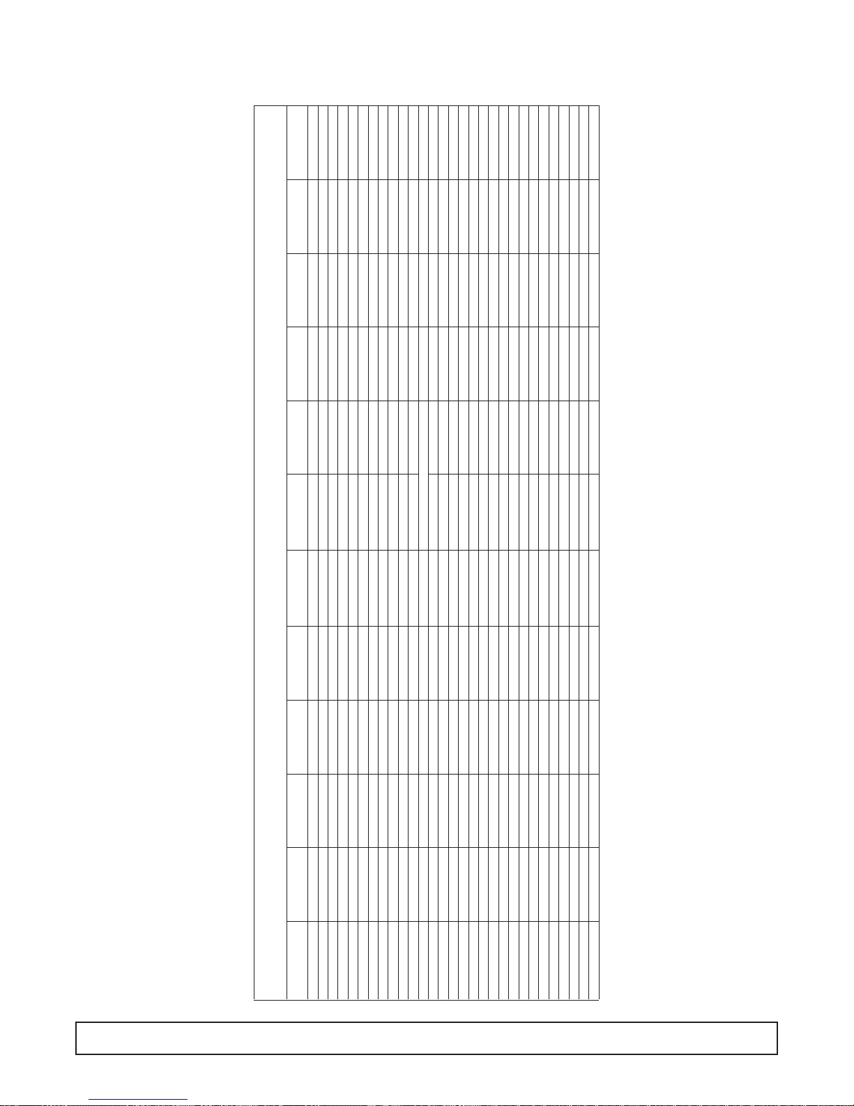
CONTROL PANEL WIRING DIAGRAM – 00-0017-10
34 WIRING DIAGRAM
REV
CODE
WIRE
DETAIL
X
YELLOW
TYPE
WIRE
RM
=
DATE
:
THK
X
GN = GREEN
PE = PURPLE
PK = PINK
GY = GRAY
TN = TAN
YW
WIRE CODE
COLOR CODE
BLACK & WHITE LEAD
123456789101112131415161718192021222324252627282930313233343536373839404142434445464748495051525354555657585960616263646566676869
RD = RED
BK = BLACK
BE = BLUE
BN = BROWN
WE = WHITE
OE = ORANGE
ITEM NO
40
(64)
IN
WIRE
TERM
IN
LTH
CLR
GA
DRAWN
APPR
XX
00-C-0017-10
XXX
DATE
2-26-96
XX
:
XX
CHKD
PART NO.
DATE
BLACK 19-A-1054-05
WHITE 19-A-1054-04
*SHIELDED CABLE
19-A-1151-00
71
72
HARNESS
19-1020-00
(59)
(60)
18PK008GX2A
18GY008GX2A
WHITE LEAD
BLACK LEAD
BROWN LEAD
ORANGE LEAD
YELLOW LEAD
RED LEAD
PURPLE LEAD
BLUE LEAD
GREEN LEAD
70 FUSE 1AMP 19-A-1049-00
*
(58)
(56)
(54)
(55)
18BN008GX2A
18BN008GS2A
18WE008GS2A
18PE008GS2A
(52)
(53)
(51)
18OE008GR2A
18WE004GG2A
18BK004GX2A
*
(41)
(44)
(40)
18RD008GR2A
18OE032SS2A
18RD008GS2A
(35)
(36)
(37)
18WE024GG2A
18BN004GR2A
18GY032SS2A
18BK036GG2A
18WE036GG2A
(30)
(34)
(33)
18BK008GQ2A
BLACK LEAD
WHITE LEAD
18BE008GQ2A
18BK024GG2A
(24)
(26)
(29)
(27)
(25)
(28)
18GY008GG2A
18GY012DG2A
18PE008GR2A
18OE004GR2A
18OE008GG2A
18WE008GQ2A
(23)
(18)
(21)
(20)
(22)
18RD004QQ2A
RESISTOR W/LEADS
18PE008GQ2A
18PE008GG2A
18PE008DG2A
18YW004GR2A
39
(15)
(16)
(13)
(17)
(14)
18YW008QR2A
18BN008GR2A
18YW008GR2A
18YW008GQ2A
18GY004GQ2A
38
(09)
(08)
(11)
(10)
(12)
18GY016GL2A
18YW020QS2A
18PE020RS2A
18BE020RS2A
18RD004GQ2A
(05)
(03)
(06)
(07)
18RD054GQ2A
BLACK LEAD
18PK054GQ2A
18PK016GL2A
18RD020GS2A
(02)
18RD008GR2A
D
RTD
GND(-)
4-20mA(+)
RECORDER
MODULE #4
CHART
PINK
TERMINAL
STRIP
RED
CONTROLLER/MONITOR
SENSOR
CIRCUIT BOARD
1
3
J4
J5
44
44
7
4
58
58
41
37
LOW VOLTAGE
RACEWAY
-
5
3
BATTERY
+
ALARM
71
71
72
72
115V
TRANSFORMER
NC
NCNONC
P/N 19-A-1151-00
230V
19-0998-00
19
BUTTON
PUSH TO TEST
C
C
15
RESISTOR
RED
RED
RED
1
1
6
6
J2
J1
GY
TERMINAL
BOARD
RD
YW
15
L
HIGH
TEMP.
INDICATOR
L
LOW
TEMP.
INDICATOR
16
12
L
52
POWER
FAILURE
55
47K
INDICATOR
56
RESISTOR
15
15
BN
WE
YW
19-1004-00
19
L
17
783
TERMINAL
BOARD
5
51
INTERIOR
1
4
24
21
14
8
2
-
25
ALARM
33
13
9
54
61
19-1009-00
19
62
64
MODULE #1
DIGIT DISPLAY
C
INPUT
+
1
3
4
TIME DELAY
22
28
+
-
SONALERT
5
6
4
3
2
TERMINAL STRIP
13
9
12
18
70
63
PK
PE
BN
36
23
36
20
33
6
RELAY
4
1
2
6V ALARM
WE
OE BK
65
LIGHT
SWITCH
NO
COM
2
NO
7
11
10
1
6
J3
1
SHIELDED CABLE ASSEMBLY
GROUND
RECPTACLE
RELAY
28
30
29
8
C
1
7
115V
CHARG
12V
115
OE
WE BK
POWER
-
E
31
RELAY
RESISTOR
47K
DOOR AJAR
E
+
D
C
AVC
32
TERM. BOARD
BK
OEBNYWRDPE
WE
#3
L
ORANGE
MODULE
26
C
NO
27
MODULE #2
ALARM SYSTEM
38
FUSE 1.0 AMP
39
BE
TO MATING PLUG
ON ELECTRICAL
BOX SEE DIAGRAM
53
67
DOOR AJAR
BUTTON
AUDIO SILENCE
35
66
69
GROUND
PE
BE
TERM. BOARD
RD
ON PANELS W/ALARM MODULE OPTION.
THESE CONNECTIONS ARE MADE IN THE RACEWAY
6
ON/OFF
68
POWER
SWITCH
286
860
59
RACEWAY
4
HIGH VOLTAGE
34

CONTROL PANEL WIRING DIAGRAM – 00-0017-12
WIRING DIAGRAM 35
CODE
WIRE
DETAIL
X
YELLOW
TYPE
WIRE
=
THK
X
GN = GREEN
PE = PURPLE
PK = PINK
GY = GRAY
TN = TAN
YW
WIRE CODE
COLOR CODE
BLACK & WHITE LEAD
123456789101112131415161718192021222324252627282930313233343536373839404142434445464748495051525354555657585960616263646566676869
RD = RED
BK = BLACK
BE = BLUE
BN = BROWN
WE = WHITE
OE = ORANGE
ITEM NO
(64)
IN
WIRE
TERM
IN
LTH
CLR
GA
XX
00-C-0017-12
XXX
XX
XX
PART NO.
BLACK 19-A-1054-05
WHITE 19-A-1054-04
*SHIELDED CABLE
19-A-1151-00
70 FUSE 1AMP 19-A-1049-00
71
72
HARNESS
PURPLE LEAD
BLUE LEAD
GREEN LEAD
19-1020-00
BROWN LEAD
ORANGE LEAD
YELLOW LEAD
RED LEAD
(58)
(60)
(59)
18PK008GX2A
18GY008GX2A
WHITE LEAD
BLACK LEAD
*
(56)
(54)
(55)
18BN008GX2A
18BN008GS2A
18WE008GS2A
18PE008GS2A
(52)
(50)
(53)
(49)
(51)
18OE008GR2A
18WE004GG2A
18BK004GX2A
18RD008DG2A
18PK024SS2A
*
(48)
(47)
(46)
(44)
(45)
18RD008GS2A
18OE024SS2A
18YW008AD2A
18BN008AD2A
18BE008AG2A
18BK036GG2A
18WE036GG2A
39
(35)
(33)
(34)
(36)
(37)
18BE008GQ2A
18BK024GG2A
18WE024GG2A
18BN004GR2A
18GY032SS2A
38
(30)
(29)
18WE008GQ2A
18BK008GQ2A
BLACK LEAD
WHITE LEAD
(28)
(27)
(26)
(25)
(24)
18GY008GG2A
18GY012DG2A
18PE008GR2A
18OE004GR2A
18OE008GG2A
(22)
(21)
(20)
(23)
(18)
18RD004QQ2A
RESISTOR W/LEADS
18PE008GQ2A
18PE008GG2A
18PE008DG2A
18YW004GR2A
(13)
(15)
(16)
(14)
(17)
18YW008QR2A
18BN008GR2A
18YW008GR2A
18YW008GQ2A
18GY004GQ2A
(11)
(12)
(10)
(08)
(09)
18GY016GL2A
18YW020QS2A
18PE020RS2A
18BE020RS2A
18RD004GQ2A
(05)
(07)
(06)
(03)
18RD054GQ2A
BLACK LEAD
18PK054GQ2A
18PK016GL2A
18RD020GS2A
(02)
18RD008GR2A
D
REV
RM
DATE
:
DRAWN
APPR
DESCRIPTION
DATE
2-26-96
:
WIRING DIAGRAM (CONTROL PANEL)
CHKD
DATE
RTD
GND(-)
4-20mA(+)
NO
NC
CONTROLLER/MONITOR
SENSOR
COM
CIRCUIT BOARD
ALARM
2
7
7
11
10
1
1
3
J4
6
J3
4
J5
44
44
58
58
CHART RECORDER
37
48
49
NOTE: WHEN CHART RECORDER IS NOT
PRESENT WIRE #48 IS CONNECTED
TO J4/pin3 ON CONTROLLER/MONITOR
AND WIRE #37 IS NOT USED.
LOW VOLTAGE
RACEWAY
PINK
-
5
3
+
BATTERY
RED
TERMINAL
STRIP
71
TRANSFORMER
BUTTON
PUSH TO TEST
C
NONCNO
NC
1
P/N 19-A-1151-00
SHIELDED CABLE ASSEMBLY
GROUND
72
C
1
6
J2
71
115V
230V
1
6
J1
72
19-0998-00
19
15
RESISTOR
15
RED
HIGH
TEMP.
INDICATOR
LL
RED
LOW
TEMP.
INDICATOR
L
RED
POWER
FAILURE
INDICATOR
56
55
52
47K
BLACK
7
WHITE
8
RED
9
6
4
SWITCH
36
2
PE
BN
36
33
RELAY
6V ALARM
65
10
11
12
13
TEMPERATURE
1
14
25
ALARM
33
13
9
9
54
61
62
64
MODULE #1
DIGIT DISPLAY
CONTROLLER
4
21
2
3
TERMINAL STRIP
13
63
#3
MODULE
DOOR AJAR
POTENTIOMETER
PK
GY
RD
YW
TERMINAL
BOARD
23
16
12
20
17
5
8
3
7
1
BN
WE
WE
OE BK
YW
TERMINAL
BOARD
19-1004-00
51
19
L
RESISTOR
INTERIOR
15
15
LIGHT
RELAY
SOLID STATE
RECPTACLE
RELAY
TIME DELAY
28
30
29
5
8
C
1
7
2
1
47
46
CHARG
E
-
+
D
C
12V
E
115
AVC
32
31
TERM. BOARD
BK OE
WE
ALARM SYSTEM
POWER
115V
RELAY
WEBKOE
BNYWRD
TO MATING PLUG
6
5
4
3
2
1
24
8
-
C
+
4
1
22
28
+
-
SONALERT
6
432
12
18
70
+
3
-
4
45
26
NO
27
MODULE #2
FUSE 1.0 AMP
PE
BE
ON ELECTRICAL
BOX SEE DIAGRAM
44
C
38
39
22
AUDIO SILENCE
35
53
67
69
GROUND
BUTTON
66
50
BE PE
RD
TERMINAL
BOARD
ON PANELS W/ALARM MODULE OPTION.
THESE CONNECTIONS ARE MADE IN THE RACEWAY
6
34
59
8
4
6
2
SWITCH
POWER
ON/OFF
68
860
RACEWAY
HIGH VOLTAGE

CONTROL PANEL WIRING DIAGRAM – 00-0058-*
36 WIRING DIAGRAM
5
2
ROCKER
4
1
ON/OFF SWITCH
BK
BN
CONTROL PANEL
BK
BN
643
872
KEYED
ON/OFF SWITCH
CONTROL PANEL
GND LEAD
HARNESS- PANEL, KEYED ON/OFF
OPTIONAL CONTROL PANEL MOUNTED ON/OFF POWER SWITCH
L
BK
BK
WE
WE
L2T2
C
T1 L1
CONTACTOR
BK/WE
DIAGRAM FOR 230/60
SEE ELECTRICAL BOX
TYP FOR 115/60 OR 220/50
WITH
INDICATOR
PUSHBUTTON
LIGHT SWITCH
BN WE
C
L
47 K
BK
GN
WE
POWER CORD
ELECTRICAL BOX
CONTROL PANEL
GND LEAD
SERVICE PLUG
HARNESS- PANEL, ROCKER ON/OFF
OPTION #1- KEYED ON/OFF SWITCH *GR-01
L
BK
BK
WE
WE
C
T1 L1
BN WE
C
12
BK/WE
GY
T2 L2
54
CONTACTOR
SEE ELECTRICAL BOX
TYP FOR 115/60 OR 220/50
ROCKER
LIGHT SWITCH
POWER CORD
DIAGRAM FOR 230/60
ELECTRICAL BOX
CONTROL PANEL
BK
GN
SERVICE PLUG
WE
OPTION #2- ROCKER ON/OFF SWITCH *GR-03
HARNESS- PANEL, PUSHBUTTON LIGHT
GY
OPTIONAL CONTROL PANEL MOUNTED LIGHT SWITCH
GY GY
BALLAST
CONNECTOR/S
HARNESS- PANEL, ROCKER LIGHT
GY
BK/WE
BN
BALLAST
CONNECTOR/S
GY
WE
PE
5 AMP-125/250V
YW OE
BE
BK
TERMINAL BOARD
WE
RD
WE
OPTION #1- PUSHBUTTON LIGHT SWITCH WITH INDICATOR *GR-02
ELECTRICAL BOX
BK/WE
5 AMP-125/250V
YW OE
BE BN
BK
RD PE
TERMINAL BOARD
WE
OPTION #2- ROCKER LIGHT SWITCH *GR-04
ELECTRICAL BOX

SECTION III
Maintenance
and
Repair
The manufacturer requires compliance to all CGC
reclamation laws by saervice companies engaging
in system processing.

WARNING
To avoid the possibility of an electrical shock, turn
OFF the thermostat and unplug the power cord of
the cabinet before cleaning or touching electrical
connections or parts.

MAINTENANCE & REPAIR
PRE-SERVICE CHECK LIST
You may avoid the cost and inconvenience of an unnecessary product call by first reviewing this check list of the
most frequently encountered situations that are not the
result of defective workmanship or materials.
COMPRESSOR RUNS TOO MUCH
1. A refrigerated cabinet automatically compensates for
product loading by running longer and more often.
Before calling for service, check running time for at
least one hour the first thing in the morning (before
store traffic starts).
2. Be sure the doors seal.A faulty gasket seal will cause
increased running time.
3. Check the room temperature.The warmer the room,
the more the compressor will run.
4. Check the condenser to be sure the face is clean.Dirt
and lint will raise pressures and increase running
time.Use a brush or vacuum to clean the condenser.
5. Be sure condenser fan operates.
6. Check to see that evaporator fans are running.
7. If product is too hard (cold), try setting the
Temperature Control (thermostat) warmer. This will
result in warmer cabinet temperature and reduced
running time.
8. Check insufficient ventilation to condenser.
CABINET DOES NOT OPERATE
1. Be sure cabinet is plugged in.
2. Check that breakers or fuses are good and all switches in the supply line are ON.
3. Be sure that cabinet Master Power Supply Switch is
ON.
4. If you are in an area with voltage problems, try shutting off all non-essential electrical equipment.
LIGHT IS OFF
1. If the cabinet is operating, be sure the lamp is properly seated in sockets.
2. If cabinet is not running, check that Master Power
Supply Switch and Light Switch are ON, fuses are
okay, no switch in the supply is OFF, and that the cabinet is plugged in.
CUSTOMER COMPLAINT ON STORED
PRODUCT
1. Check cleaning solutions used inside cabinet.
2. Check cleaning solutions, paint, or other contaminants used in store maintenance.
3. Sometimes the ingredients used in some products or
containers will contaminate other products.
4. Be sure to follow a weekly schedule for cleaning cabinet interior.
SERVICE
In the event of a malfunction, damage to the cabinet,
or if the cabinet requires service beyond the items in
the “Pre-Service Checklist,” contact your local service
company or the dealer from whom the cabinet was
purchased.
POWER FAILURE
Do not open the cabinet doors unnecessarily if power is
cut off due to electrical failure.The cabinet will start up if
the power supply returns, but will require sufficient time
to reach maximum cold storage performance.
CABINET FAILURE
1. If the cabinet has stopped operating, check that the
cabinet is securely plugged in and turned on.Contact
a licensed electrician to locate and correct any power
supply problems.
2. Do not open the cabinet doors unnecessarily.
3. Provisions for other storage of the product may be
required to prevent spoilage.
If you call for service, describe your problem and giv e the
following information to the service representative:
Cabinet Model No. ____________________________
Part No. ____________________________________
Serial No. __________________________________
(These numbers are located on a silver serial number
rating plate in the upper left side of the cabinet interior.)
MAINTENANCE & REPAIR 39

TOOLS:
To provide full service diagnostics and repairs on these
cabinets, the following tools are needed:
A Multimeter
An Electronic Leak Detector
An Electronic Micron Gauge
A Vacuum Pump capable of pulling to 50 microns
Four Hand Valves
A Compound Gauge Set
A cylinder of nitrogen with a regulator capable of 10 to
400 pounds.
Standard refrigeration hand tools, e.g.: wrenches, tube
cutter, swage and flare tools, wire strippers, wire crimp.
ers, wire cutters, slot and phillips head screwdrivers.
PRODUCT HISTORY
The first rule in servicing a refrigeration system is to
determine if the problem is an electrical or mechanical
failure.
First, try to obtain the product’s history of operation
from the customer.This will help identify the source of
the problem.
Good facts from the cabinet user can help identify
whether the problem is electrical, within the refrigeration system, or a “misapplication by the user”.Get the
history of operation and failure by asking these questions:
1) Were there any brown-outs or power outages that
they are aware of?
2) Is the cabinet on a dedicated circuit?
3) Has any other equipment in this area had operational problems?
4) When was the last time the cabinet’s operation was
confirmed as working properly?
5) When was a problem noticed?
6) How long has the equipment run without this problem? (Years? Weeks? Days? Hours?)
7) Was anything tried prior to your arrival?
The refrigeration system should only be entered if it is
absolutely necessary. It is critical that a clean, uncontaminated system be maintained.
If a system is unable to reach the proper operating
temperature, a test of the unit’s mechanical refrigeration components is required.
COMPRESSOR EFFICIENCY TEST
To test the compressor, place compound gauge on the
compressor’s suction port.
While the compressor is running, close off the suction
line so that only the port and valve are part of the compressor’s low side.
When the valve is closed and vacuum has started, time
how long it takes to pull the compressor’s low side to its
lowest possible vacuum.
Compressors used on these cabinets should be capable
of pulling at least 20 to 22 inches of vacuum in less than
40 seconds.
Next, shut off the compressor and watch the gauge. A
one or two inch rise in pressure is acceptable, since a
small amount of freon may remain on the low side of the
compressor, after which the reading should stabilize.
If the pressure continues to rise, the discharge reeds in
the valve head ha ve f ailed, allowing high pressure gas to
return to the compressor.
If the compressor pulls less than 20 inches, the suction
reeds have failed.
If the compressor takes longer than 40 seconds to pull
to its ultimate low vacuum, one or both cylinders are not
functioning as they should. Any reading less than these
will require replacement of the compressor.
ENTERING THE SYSTEM
Entering the system should only be done as a last
resort. Extreme care must be used no matter what the
reason for entering the system. Of course there are
times when it cannot be avoided, such as component or
compressor replacement, or a leak within the system.
The system must also be entered any time you need to
obtain the operating pressures.Again, use extreme caution to avoid any possible contamination.
Cabinets that use hermetic compressors typically do not
have valve ports, so therefore process stubs for both
suction and discharge sides of the system were added.
Line taps should only be used to obtain pressure readings, and not for the reprocessing of the system. The
opening of a line tap is too restrictive for the pressure of
vacuum procedures.
On a hermetic compressor system, once you have
determined that reprocessing a system is required,
recover refrigerant and remove the line taps.
40 MAINTENANCE & REPAIR

Install hand valves at the process stub ends. Hand
valves will be less restrictive to flow because of a larger
opening. They will also be easier to use during repair
procedures.
EVACUATION
Once the system has been cleaned and components
have been replaced, you are ready to initiate the final
servicing procedures necessary to achieve proper cabinet operation. Drier should be replaced prior to system
processing.
Pull an evacuation to approximately 50 microns.
CHARGING
You should use a charging cylinder to measure in the
correct amount of refrigerant.The charging methods are:
1. Add the refr igerant to the system until you reach a
balanced pressure. This will give you an approximate static charge.
2. Weigh in the refrigerant using a scale calibrated in
ounces.
The cabinet’s operation is now ready to be tested. A
final check of the refrigeration lines should be made
before running the cabinet.
Be sure the refrigeration lines are not kinked or rubbing against each other.
Also check that the door seals properly. An air leak will
affect proper operation, and the cabinet’s ability to
reach its coldest temperature.
Run the cabinet at both 100% run, and a cycling temperature for at least 24 hours. If the temperature and
pressures are correct, the system can be considered
repaired.
Hermetic systems should now have their process
stubs pinched off, hand valves removed and the ends
brazed shut.
MAINTENANCE & REPAIR 41

COMPRESSOR INSTALLATION & MAINTENANCE
TO CHANGE THE COMPRESSOR:
1. Disconnect the power supply to the cabinet.
2. Disconnect the power supply leads at the
compressor.
3. Disconnect wires to relay and capacitors.
4. Remove relay and starting capacitor and install on
new compressor.
5. Remove defective compressor from condensing
unit base.
6. Set new compressor in place.
7. Reconnect relay and capacitor wires.
8. Reconnect power supply lead.
9. Leak test, evacuate, and weigh in charge.
CHANGING DRIER
If flare connected, make sure flares and faces of fittings on new drier are clean and in good condition
before installing new drier.
If sweat connected, clean tubing close to original
drier before cutting tubing in clean area. Check that
ends of the replacement drier are clean, then make
brazed connection using as little heat as possible.
Cut tubing only with tube cutters, not hacksaws, to
avoid metal filings from entering the system. Driers
must be replaced any time you enter the system,
except when you are obtaining pressures.
SERVICE VALVES
The compressors on some cabinets have service
valves for measuring suction and discharge pressures.
Two types are used. The first type is connected directly to the compressor body or shell and back seats to
connect gauges to the access port. The second is on
the end of a process tube and requires a gauge or
charging line with a depressing pin to open valve when
the connection is made.
This type valve should be tightly
capped except when making the
gauge connection.
TO CHECK FOR OPEN WINDINGS
Use a multimeter. Measure ohms between “C” and “R”
and between “C” and “S.”
If windings are O.K., multimeter will show a resistance
reading between terminals.
If there is no reading, the compressor winding or
windings are open and the compressor should be
replaced.
TO CHECK FOR GROUNDED COMPRESSOR
Use multimeter.Touch probe from each terminal to an
unpainted surface of compressor body. If there is no
ground, there will be no change of the meter.
WARNING: Be Careful Not to Touch
Uninsulated Parts of the Meter Probes
A reading indicates a ground and the compressor
should be replaced.
If there is voltage at the compressor terminals and the
compressor tries, but does not run, check voltage at
the compressor terminals while attempting to start the
compressor.If the voltage at the compressor terminals
is below 90% of the nameplate voltage, it is possible
the motor may not have developed sufficient torque to
start. Check to determine if:
A.Wire sizes are adequate.
B. Electrical connections are tight.
C. The circuit is not overloaded.
D. The power supply is adequate.
A defective relay or capacitor may prevent the compressor starting.
TO CHECK OUT THE RELAY
1. Disconnect the cabinet from the power supply.
2. Remove the wires from the relay.
3. Touch probes to the contact terminals. Meter
should show infinity if closed.
4. Touch probes to the terminals of coil. The meter
should show a resistance reading.
If items 3 and 4 are O.K., the relay is good. If items 3
and 4 are not as indicated, change the relay.
CAUTION:
42 MAINTENANCE & REPAIR

TO CHECK CAPACITORS
1. Disconnect the cabinet from the power supply.
2. Make sure the capacitors are discharged before
touching terminal. (Shunt across the terminal of
capacitor with a heavy insulated wire.)
3. Remove the wires from the capacitors.
4. Any capacitor found to be bulging, leaking, or damaged should be replaced.
5. Use a multimeter to check the run and start
capacitors for shorts or open circuits.
With a good capacitor, the indicator should first move
to a reading and then gradually increase to infinity.
If there is no reading change, an open circuit is indicated.
If the multimeter remains on a low resistance reading,
a short circuit is indicated.
On run capacitor, touch probes to metal case and
each terminal. If meter show any reading, a ground
is indicated. All defective capacitors should be
replaced.
MAINTENANCE & REPAIR 43

CLEANING & MAINTENANCE
CLEANING THE CABINET EXTERIOR
Wipe the exterior occasionally with a cloth dampened
in mild detergent water; rinse, and wipe dry with a soft,
dry cloth. Do not use abrasive or caustic cleaners or
scouring pads.
CLEANING THE CONDENSER - FIG. 1
1. Periodic cleaning of the condenser, located in the
machinery compartment, can be easily accomplished by brushing the coils with a soft brush and/or
using a vacuum cleaner with a brush attachment.
2. Be sure that dirt, dust, and collection of other
debris do not build up to a point air circulation
through the condenser is restricted.
3. Clean the condenser at least twice a year.
CLEANING THE STORAGE
COMPARTMENT
IMPORTANT: Do not use any objects or cleaners
which may leave residues, odors, or particles.
Avoid the use of strong chemicals or abrasive
cleaners which may damage the interior surfaces
and contaminate product within the storage
area.
1. Remove product and store in another suitable cabinet, if possible. Be sure to prevent spoilage of the
product which may occur if it is left at room temperature.
2. Turn OFF the Master Power Supply Switch.
3. Remove the shelving.
4. Wash the inside surface of the doors and the entire
interior storage area with warm water and baking
soda solution—about a tablespoon of baking soda
per quart of water. Rinse thoroughly with clear water
and wipe dry. This procedure can also be used for
cleaning the door gaskets.
5.Wash, rinse, and dry the shelving while it is outside of
the cabinet, using the same procedure as described
for the storage area.
6. Be sure to correctly reinstall the shelving, turn ON the
Master Power Supply Switch, check the setting of the
Temperature Control, and allow time for cooling of the
storage area before storing product.
WARNING
To avoid the possibility of an electrical shock, turn OFF thermostat and unplug the electric cord of the cabinet before cleaning
or touching electrical connections or parts.
CAUTION:
Make sure cabinet is disconnected from its power source prior to any
cleaning or maintenance.
FIG. 1
44 MAINTENANCE & REPAIR

The ballast is located in the machinery compar tment
(A), attached to the back of the electrical control box
(B).
1. Disconnect the power to the cabinet.
2. Remove the front panel.
3. Remove the cover panel on the electrical wiring box.
4. Disconnect the leads to the ballast.
5. Replace the ballast with correct part.
6. Replace the electr ical wir ing box cover panel.
7. Replace the front panel.
8. Reconnect the power to the cabinet.
BALLAST REPLACEMENT
Figure 1
Figure 2
MAINTENANCE & REPAIR 45

A nine pin wiring harness has been added to the
upright models (med & low).
1. Electr ical Box to cabinet
2. Main wir ing har ness to evaporator area.
ELECTRICAL BOX / QUICK CONNECT
11
11
22
22
46 MAINTENANCE & REPAIR

Disconnect the power supply to the cabinet.
Access the raceway (top or bottom mount) by remov-
ing the front panels.
Remove the raceway cover.
1. Terminal board (power to mullion heater).
2. Heated door receptacle.
3. Door switch.
4. Fluorescent light har ness.
CABINET RACEWAY / LOWER FRONT PANEL
11
11
22
22
33
33
44
44
MAINTENANCE & REPAIR 47

INSTRUCTIONS – SOLID DOOR REMOVAL, INSTALLATION
& ADJUSTMENT
48 MAINTENANCE & REPAIR
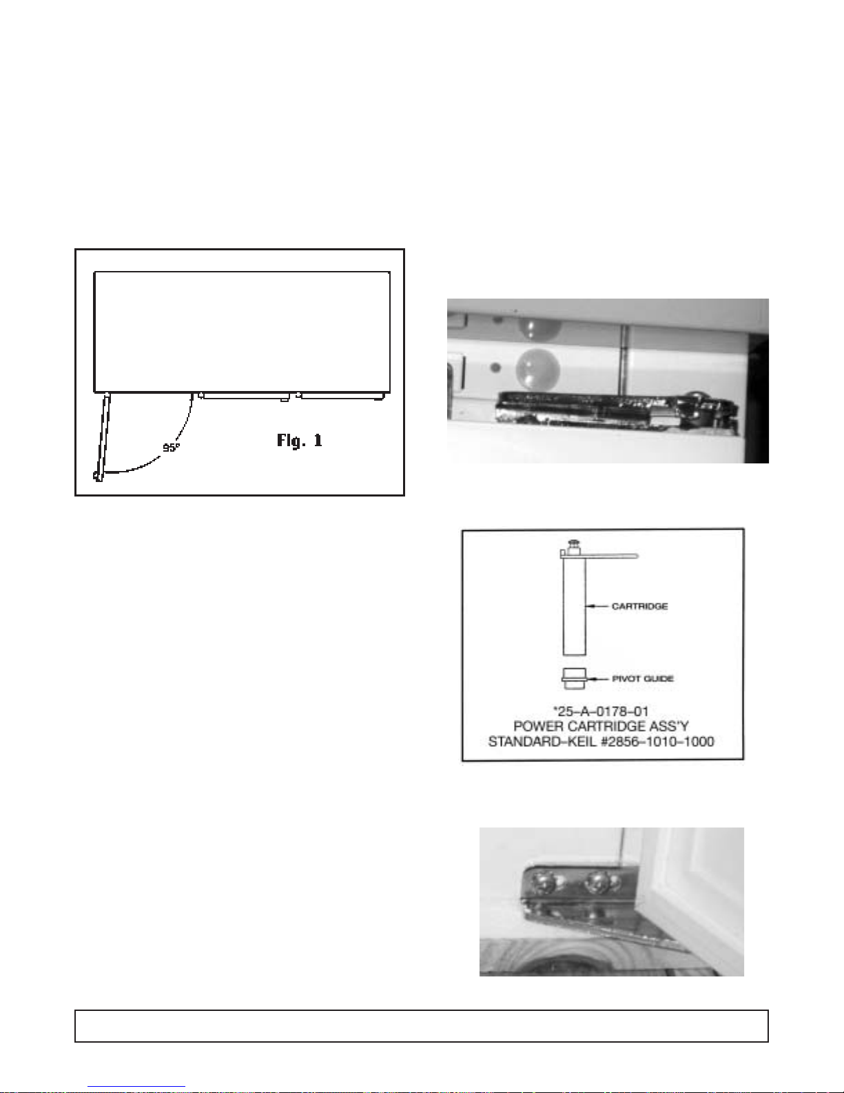
CAM HINGE DOORS – OPERATION & REMOVAL
(Solid Door Cabinets Only)
MAINTENANCE & REPAIR 49
HOLD-OPEN FEATURE
The doors can be opened up to a 95° angle and will
maintain that position for loading or unloading the storage compartment. Refer to Fig. 1.
Door Removal
The door can be removed by opening door 180°.
Grasp door with one hand. Remove two screws located in top bracket of door opening.Door can be lifted up
and away from the BTM Bracket pin.
NOTE: Door closer cartridge is spr ing loaded.
ALIGNING THE DOORS
Proper alignment of the cabinet doors will eliminate
hinge binding and provide correct gasket seal.
Top Bracket door opening slotted holes for up and
down adjustment.
Spring Cartr idge located in door, can be removed by
two screws Top of Door.
BTM Bracket Door opening slotted holes are for
adjustment Left or Right
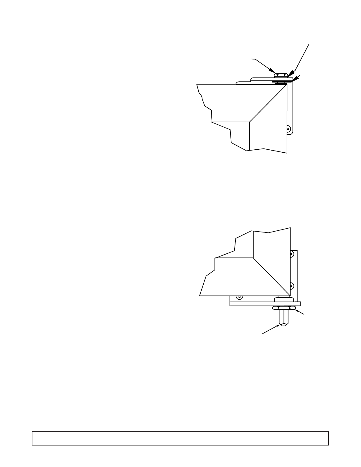
TORSION ROD HINGED DOORS - Maintenance & Removal
GLASS DOOR CABINETS ONLY
MAINTENANCE – ALIGNING DOORS
Proper alignment of the cabinet doors will eliminate
hinge binding and provide correct gasket seal.
1. Check the level of the cabinet and door alignment
by firmly closing each door.Observe the movement
of the other doors. They should open slightly, then
close and seal.
2. The hinge wings fastened to the cabinet door have
slotted mounting holes for adjustment.
3. Additional adjustment can be made by adding
shims between the hinge wing and either the door
or the cabinet face.
REMOVING DOORS:
1. Loosen lower hex nut (Nut “A”) and release tension
on the torsion rod.
2. Remove the hitch pin from the upper hinge pin.
3. Hold the door steady and unscrew the pin at top of
the door.The door can now be lifted out of the lower
hinge- bracket
REINSTALLING DOORS:
1. Set lower square shaft on door in lower hinge
bracket
2. Insert top hinge pin and tighten to 12 ft./lbs. torque.
NOTE:Washer must be in place so top pin will not
loosen and disconnect from door hinge.
3. Insert hitch pin through hole in upper hinge pin.
4. Run Nut “A” up snug. (You may have to loosen Nut
“A” as you tighten tension as noted in Step 5.)
5. Set tension on door by turning square shaft in the
direction the door closes. Set tension so that the
door will self close when opened approximately 1".
(Do not overtighten so door will slam.) Tighten Nut
“A” so tension can be maintained.
NUT "A"
SQUARE
SHAFT
HINGE PIN
WASHER
HITCH
PIN
TORQUE ROD REMOVAL
1. Loosen nut “A” to remove door.
2. Attach vice grips to shaft.
3. Dr ive torque rod out of door.
4. Install new rod into keyway slot in door frame.
5. Reattach nut after installing door.
6. Turn shaft clockwise then lock nut “A”.
7. Add torque until door will close by itself.
50 MAINTENANCE & REPAIR

DOOR HANDLE & LOCK REPLACEMENT
SOLID DOOR
The door handle can be removed or replaced by
removing the two chrome plug buttons in each end of
the handle, “A”.
The lock mechanism can be removed by drilling out
the two pop rivets in the stainless steel cam cover –
“B”.
Access can be gained to the retainer clip which holds
the lock barrel in place.The lock can now be removed.
GLASS DOOR
The door handle can be removed or replaced by
pulling the door gasket out of its retaining groove just
behind the door handle and inserting a philips head
screwdriver into the recessed holes provided.
Retainer screws hold the handle in place.
The lock mechanism is not replaceable on glass door
models.
AA
AA
BB
BB
BB
BB
MAINTENANCE & REPAIR 51

DOOR GASKET REPLACEMENT
The gasket is replaceable on glass or solid door models.
A retainer is molded into the door frame.The door gasket is then tapped into the retainer and secured for airtight door seal.
1. Remove door from cabinet.
2. Lay door front down on a flat, firm, nonscratch surface.
3. Pr y up one corner of gasket with a putty knife or
screwdriver. Pull gasket from perimeter of door
retainer.Clean new gasket and straighten to insure
proper fit.
4. Pull gasket from perimeter of door retainer.
5. Clean new gasket and straighten to insure proper
fit.
6. Place gasket over retainer in door frame.
7. Using a rubber mallet, tap the gasket into the
retainer. (NOTE: Gasket can be soaked in warm
water to make pliable.)
8. Place door back onto cabinet.
52 MAINTENANCE & REPAIR

CENTER MULLION HEATER REPLACEMENT
DISCONNECT POWER SUPPLY TO CABINET
Grip inner mullion cover panel at top while pulling on
the inner mullion panel. Spread plastic extrusion apar t
at the top. Continue down the mullion assembly until
mullion cover is free.Set aside.
Again spread plastic extrusion apart and carefully
remove the insulation material. This will expose the
mullion heater taped in place. Heater leads are routed
either up or down (top mount or BTM mount) into an
electrical raceway to a terminal board where they can
be disconnected and replaced. Assemble in reverse
order.
Note: reseal holes provided with a silicone sealant
upon repair.
MAINTENANCE & REPAIR 53
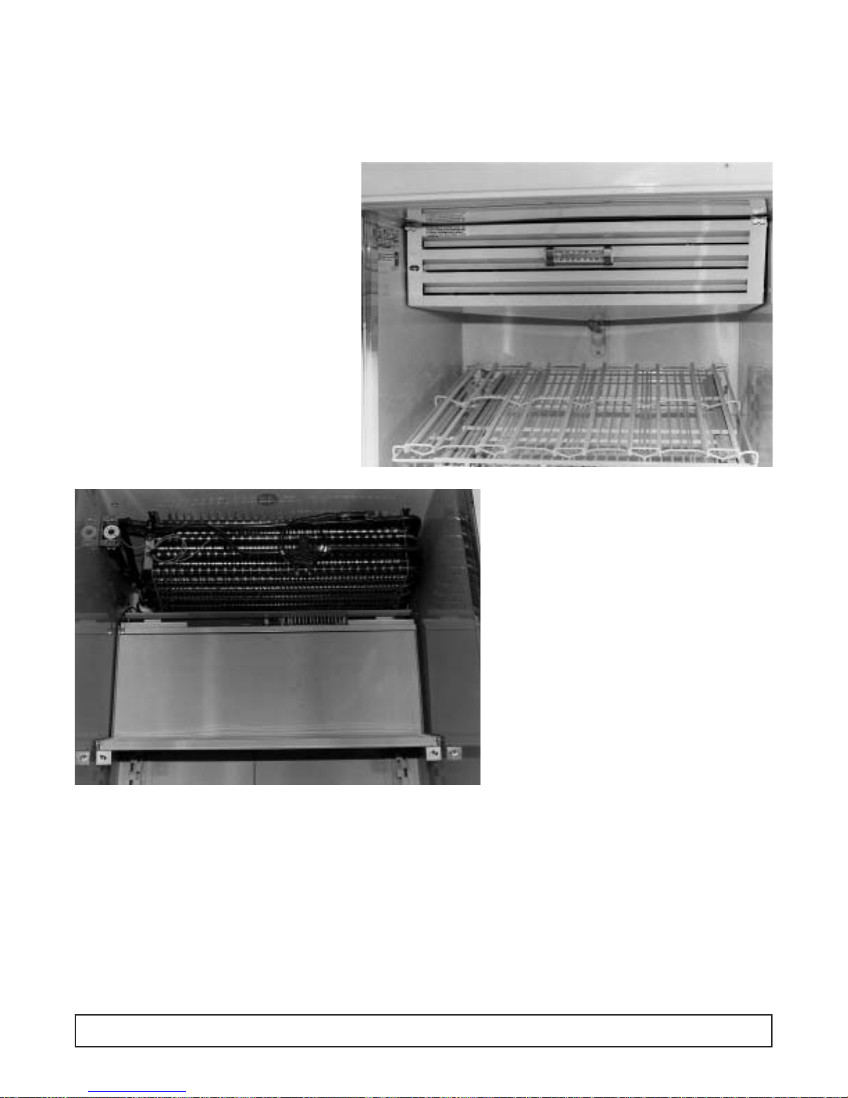
EVAPORATOR DRAIN PAN REPLACEMENT
The evaporator drain pan is located in the upper interior
of the cabinet. It pivots down for ease of accessibility.
1. Disconnect the power to the cabinet
2. Release R.H. and L.H. Lock screws.
3. Drop the front of the pan and swing it back.
4. Disconnect the ground wire.
5. Raise the pan, unhook from back.
6. Remove the drain line from the drain hole.
7. Remove the pan from the cabinet.
8. Reconnect the power to the cabinet.
54 MAINTENANCE & REPAIR

LIGHT SWITCH REPLACEMENT
On commercial models, the light switch is located
inside the cabinet. It is on the light channel assembly.
On scientific cabinets, the light switch is located on the
front control panel.
1. Disconnect the power to the cabinet.
2. Remove the plastic lamp shield. Remove the lamp
bracket from the cabinet.
3. Remove the lock nut on the switch body.
4. Disconnect wire leads.
5. Connect new switch.
6. Replace the lock nut.
7. Replace the lamp shield.
8. Reconnect the power to the cabinet.
MAINTENANCE & REPAIR 55

FLUORESCENT BULB REPLACEMENT
1. Remove the plastic outer lamp shield.
2. Grasp the bulb.
3. Raise the bulb up. Pull out of the socket.
4. Remove the lamp shields and the end caps.
5. Place a new bulb in the shield. Attach the end caps.
6. Inser t the bulb into the cabinet, push up and snap
into place.
56 MAINTENANCE & REPAIR
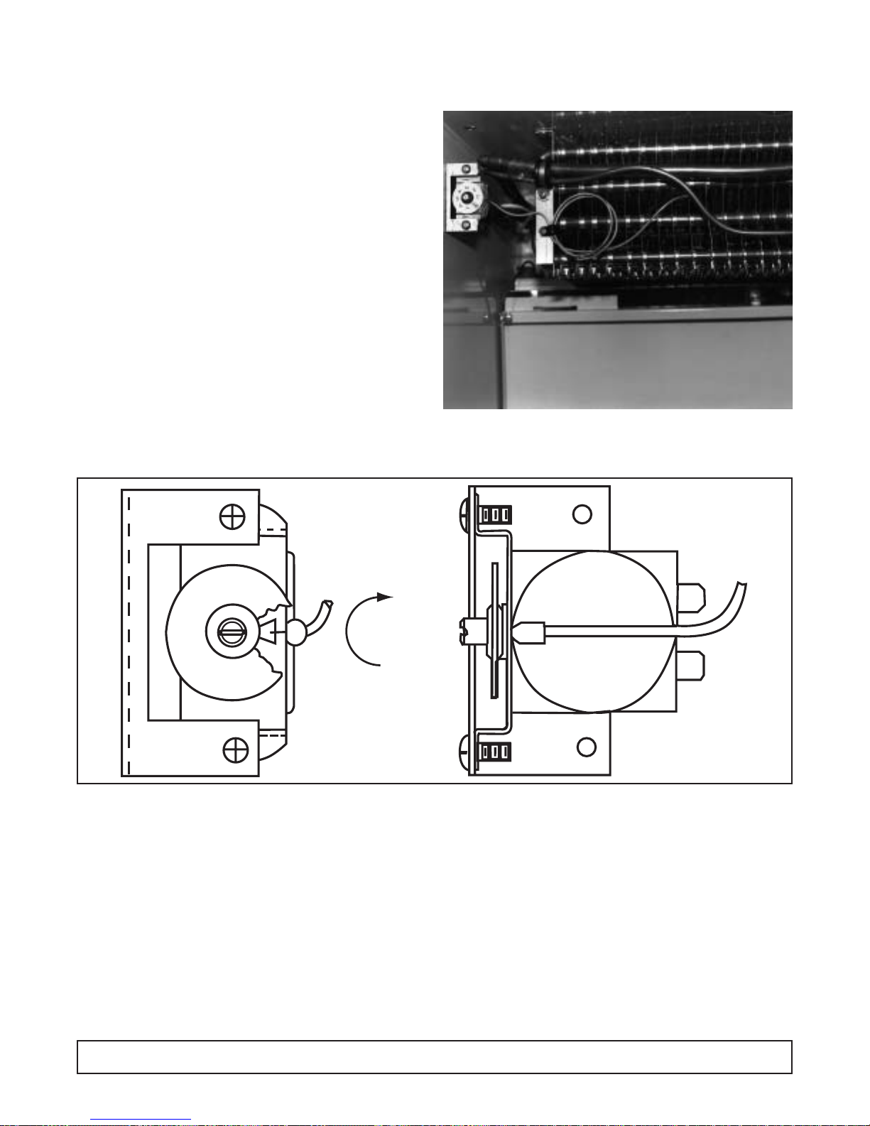
The thermostat is located in the upper left hand corner
of the drain pan area. It functions to control the temperature within the cavity of the cabinet. Rotate the
thermostat clockwise for colder and counterclockwise
for w a rmer.
NOTE: location of bulb well in coil.
1. Disconnect power to the cabinet.
2. Lower evaporator drain pan.
3. Remove screws on mounting bracket.
4. Slide ther mal bulb assembly out of cabinet.
5. Replace thermostat into position as indicated in
above photo.
6. Replace screws.
7. Replace evaporator drain pan.
8. Reconnect power to cabinet.
(Do not crimp capillary tube. This will affect thermostat’s performance or make it inoperable.)
TEMPERATURE CONTROL
Position #7 is the coldest.
Position #1 is the warmest.
Temperature Range Adjustment
MAINTENANCE & REPAIR 57
2
1
3
4
7
5
6
Colder
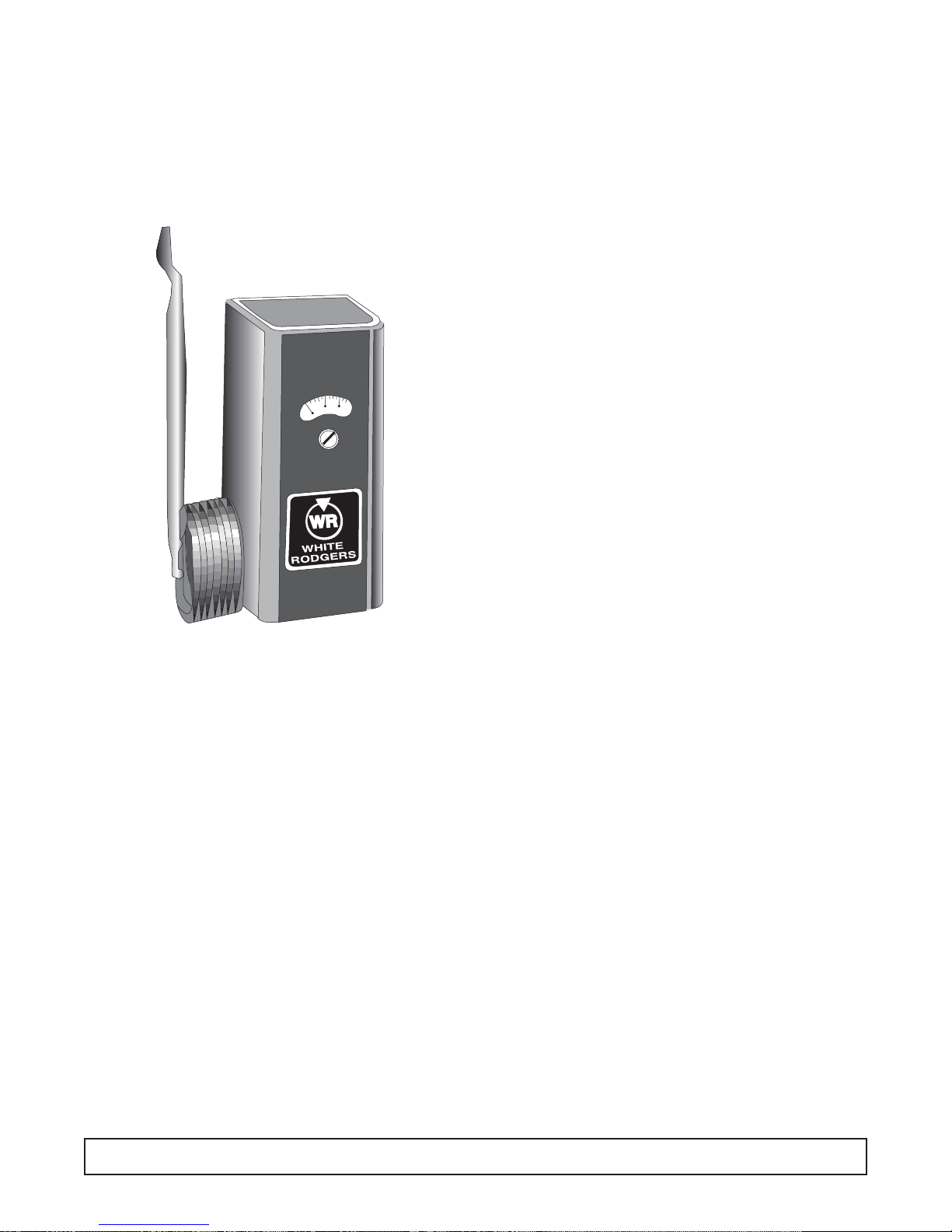
TEMPERATURE CONTROL
Flammable Material Storage &
Chromatography Refrigerators
SPECIFICATIONS
FEATURES:
Temp. Range: -30°F / -34°C
Adjustable Differential
Full Motor Rating
Capillary Bulb Switch Elec. (Full Load)
Type Range °F Diff. °F Length Size Action Rating 120V AC 240V AC
1609-101 -30 to +90 Adj. 31⁄2 to 40 5 ft. 53⁄4" x 3/8" Close FGH 16A 8A
(-34 to +32°C) (2 to 22°C) on Rise
58 MAINTENANCE & REPAIR

METERING DEVICE REPLACEMENT
The refrigerant metering device in this cabinet is
expansion valve. It is a Sporlan FBV 1/4-C. It is located on the face of the evaporator coil behind the drain
pan. (Super heat setting 6° to 8° valve is field
adjustable.)
1. Disconnect power to the cabinet.
2. Remove the evaporator drain pan.
3. Isolate the valve from the remainder of the system.
4. Remove the valve and replace with exact part num-
ber new valve.
5. Reposition the sensing bulb in original location.
6. Replace the drain pan.
7. Reconnect power to the cabinet.
(Non-adjustable Shown)
MAINTENANCE & REPAIR 59

EVAPORATOR FAN MOTOR REPLACEMENT (Rear Fan)
1. Disconnect the power to the cabinet and locate the
evaporator fan in the cabinet interior behind the
evaporator coil.
2. Remove the fan guard by rotating it counter clock-
wise to the position shown.
3. Remove the fan and bracket assembly by rotating it
to the position shown.
4. Lower the fan assembly and remove the tw o screws
that fasten the motor to the bracket.
Note: To assist the removal of the guard and bracket,
press on the detent bumps to guide them out of the
obround holes.
60 MAINTENANCE & REPAIR
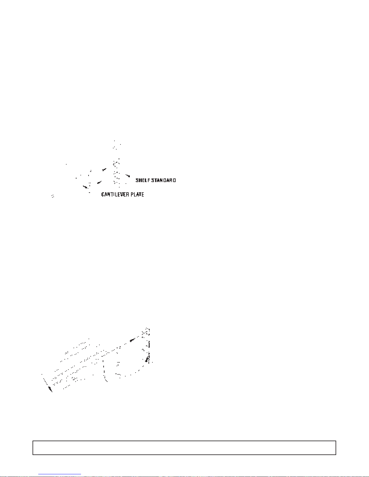
SHELVING / DRAWER
Installation & Adjustment
To install shelves or drawers in a level position, insert
the cantilever plate tabs into the rectangular holes in
the desired position on the shelf standard. Lower the
rear of the shelf so that the slots in the plate are completely down over the bottom of the holes.
NOTE: Suppor ting the front of the shelf with one hand
while pushing down on the rear of the shelf will help
ease installation.
To slope shelves, insert the cantilever plate tabs into
the rectangular holes in the desired position on the
shelf standard. Lift up on the rear of the shelf so that
the top tab is locked behind the top of the rectangular
hole. Hold the rear of the shelf up while lowering the
front of the shelf until the bottom tab is inserted in the
appropriate hole in the shelf standard.
MAINTENANCE & REPAIR 61
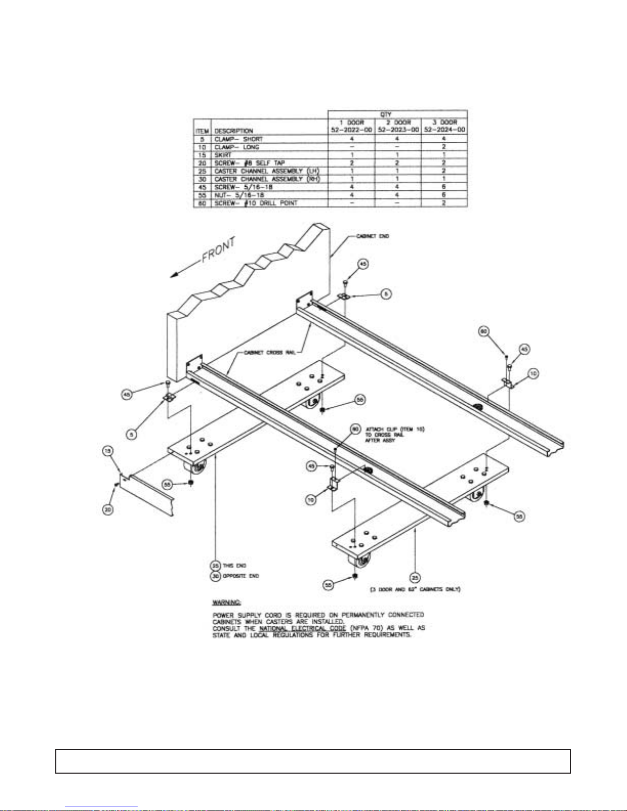
CASTER INSTALLATION INSTRUCTIONS
62 MAINTENANCE & REPAIR

ELECTRICAL &
REFRIGERATION
INFORMATION
BT30RF-FMS
Flammable Material Storage
Refrigerator/Freezer
To meet the requirements for storing flammable
material, cabinet has no openings, other than the
door, or any electrical components below the
compressor compartment.
NOTE: Do not modify cabinet or remove label on
the front which specifies storage limits.
PERFORMANCE CHARACTERISTICS: TEMPERATURE
Refrigerator: 4°C (38°F)
Freezer: -15°C (5°F)

ELECTRICAL & REFRIGERATION SPECS. BT30RF-FMS
Medium Temp., Solid, 1-Door Refrigerators
Compressor Model Number Americold HP110-1-3083
Compressor BTUH / -10°F Evaporator 1013
Recommended Operating Temp. Range (F/C) 35°F to 50°F (2°C to 10°C)
Cabinet V olts 115
Expansion Device Capillary .031 x 7"
Charge Refrig.Type / Oz. / Grams R404A / 13 / 368.5
SYSTEM COMPONENTS – R-404A
AMBIENT 70°F / 21.1°C 80°F / 27°C 90°F / 32.5°C
Cavity Temp. (F/C) 37 / 2.7 42 / 5.5 44 / 6.6
Suction Pressure (PSIG / Kpa) 4.8 / 33 8.1 / 56 11.9 / 82
Discharge Pressure (PSIG / Kpa) 180 / 1241 227 / 1565 262 / 1806
Compressor Amps 1.2 1.2 1.3
Total Refrigeration Amps 1.2 1.3 1.4
Freezer Temp. -3 / -19.5 -2 / -18.9 8 / -13
SYSTEM PERFORMANCE
ELECTRICAL / REFRIGERATION SPECIFICATIONS 65

EVAPORATOR LAYOUT
This cabinet is of standard design with the exception
of a freezer compartment located at the top interior of
the cabinet - “A”.
Depending on the application and number of door
openings, this cabinet will need to be manually
defrosted. A stainless steel pan has been provided to
collect the water during a manual defrost.
TO DECONTAMINATE
Should more extensive cleaning and decontamination
be necessary, the freezer door can be removed and the
evaporator assembly pivoted down for complete access
to the cabinet interior. The seam of silicone rubber
sealant may also be removed and replaced if needed.
TO REMOVE FREEZER DOOR
1. Open freezer door and remove top thumbscrew
securing hinge support bracket to the cabinet wall.Tilt
bracket forward and lift door off hinge pin.
2. Remove second fastener and hinge support bracket.
TO TILT FREEZER EVAPORATOR
ASSEMBLY DOWN
1. Pull tray and remove it from under freezer compartment.
2. Remove freezer door.
3. Remove thumbscrews, lower left and right front side
of evaporator freezer interior.
4. Carefully swing down front edge of evaporator freezer assembly for full access to back of freezer and
upper interior cabinet walls. Thermostat bulb may
have to be disconnected.
5. Reverse process to reassemble.
NOTE:Door may be hard to open for a short period after closing.
Wait a few seconds to allow interior air pressure to balance.
DEFROSTING AND CLEANING
To delay the need for a complete defrost, a plastic
scraper may be used to scrape frost off of evaporator
freezer surfaces.
However, a complete defrost will be required periodically. To defrost, perform the following:
1. Unload product from cabinet.
2. Turn master power supply switch to “OFF,” and
unplug power supply plug.
3. Collect defrost water in tray under evaporator
freezer. A pan of warm water set in the freezer, or
a fan blowing into it, will speed the process.
4. Wipe all freezer and drain tray surfaces clean.
Let it dry.
5. Remove shelves and shelf standards if necessary
to wipe down and dry refrigerator compartment.
6. Retur n all components; plug in power supply cord;
turn master supply switch to “ON.”
7. Once cabinet has attained desired temperature
reload cabinet with product.
AA
AA
66 EVAPORATOR LAYOUT

THERMOSTAT BULB LOCATION & BT30RF-FMS
SOLAR DIGITAL THERMOMETER OPT.
These bulbs are located at the rear left hand side of
the freezer box.
The thermostat is mounted to the electrical box on the
right hand side. The temperature is set in degrees
Celsius (Figure 1).
11
11
THERMOSTAT BULB LOCATION & SOLAR DIGITAL THERMOMETER 67

CONDENSING UNIT AREA BT30RF-FMS
1. Compressor
2. Thermostat
3. Perimeter hot gas loop
4. Condenser coil
5. Strainer / Drier
6. Heat exchange
11
11
55
55
66
66
Rear View
22
22
33
33
44
44
68 CONDENSING UNIT AREA

ELECTRICAL &
REFRIGERATION
INFORMATION
BT30RF-EXPR
Explosion Proof
Refrigerator/Freezer

EXPLOSION PROOF REFRIGERATOR/FREEZER BT30RF-EXPR
The model 525D is also UL listed for storing
Flammable Materials. DO NOT MODIFY CABINET
OR REMOVE LABEL ON THE FRONT WHICH
SPECIFIES STORAGE LIMITS.
CONTAINER REQUIREMENTS
Refer to the latest edition of the following codes to
determine correct container requirements and the definition of flammable or combustible liquids.
National Fire Protection Agency (NFPA) 45 Fire
Protection for Laboratories using Chemicals.
National Fire Protection Agency (NFPA) 99 Health
Care Facilities Chapter 7, Laboratories in HealthRelated Institutions.
NFPA Address: Batter ymarch Park
Quincy, MA 02269
You must follow these codes when storing flammable
materials
The refrigerator/freezer complies
with the following:
1. U.L. Listed, Commercial Refrigerator/Freezer for
Haz-ardous Locations. Also Listed for Flammable
Materials Storage. Control number 47R6.
2. For use in Class 1, Division 1, groups C and D Hazardous Locations.Operating Temperature Code, T4A.
3. Meets Requirements of OSHA 29CFR 1910.307.
4. Accepted for use:The City of New York
Department of Buildings
MEA 327-87-E
CAUTION:
TO PREVENT IGNITION OF HAZARDOUS
ATMOSPHERES, DISCONNECT THE PRODUCT FROM
THE SUPPLY CIRCUIT BEFORE OPENING ELECTRICAL
BOXES. KEEP ASSEMBLY TIGHTLY CLOSED WHEN IN
OPERATION.
For Satisfactory Operation
1. The cabinet should be free standing with a mini-
mum of 4" between the cabinet rear and the wall.
To allow air flow over the compressor and machinery compartment, a minimum of 12" overhead
clearance should be provided.
2. Level cabinet so door will slowly close when held
open about 4" and released. This setting assures
self closing if the door is closed hard enough to
rebound open.
ELECTRICAL SUPPLY REQUIREMENTS
The electrical power supply must be installed according to the latest edition of the NATIONAL ELECTRICAL CODE – specifically Article 510 – Hazardous
(Classified Locations - Specific).Appropriate materials
and wiring methods must be used in order to comply
with the current National Electrical Code for Class 1,
Group I and D area installation. All local and other
appropriate codes must be followed.
WARNING:
Be absolutely sure that the surrounding location has
been checked for the absence of explosive concentrations before any electrical work is started.
Over current Protection: 15 amps. (If fuses are used
use time delay type.)
GROUNDING
WARNING:
For personal safety, this cabinet must be properly
GROUNDED. The ground wire to the cabinet must
be installed on the green screw located in the
conduit outlet box. (Refer to drawing.)
The conduit outlet box is where the incoming power
wires are connected to the cabinet wires.
The incoming ground wire must be properly installed
from the power supply. Consult a licensed electrician if
you have any doubt about this wire being properly
installed.
EXPLOSION PROOF REFRIGERATOR/FREEZER 71

DEFROSTING & CLEANING
While scraping frost off of evaporator freezer surfaces
with a plastic scraper will delay the need, a complete
defrost will be required periodically.To defrost:
1. Unload cabinet of product.
2. Disconnect or tur n off the power supply.
3. Collect defrost water in tray under evaporator freez-
er. Pans of warm water set in the freezer, or a fan
blowing into it will speed the process.
4. Wipe all freezer and drain tray surfaces clean and dry.
5. Remove shelves and shelf standards if necessary,
to wipe down and dry refrigerator compartment.
6. Retur n all components; connect power supply.
7. Once cabinet has attained desired temperature,
reload cabinet with product. Intervals between
defrosting will depend on product and number of
door openings, humidity, ambient temperature, etc.
To Decontaminate
Should more extensive cleaning and decontamination
be necessary, the freezer door can be removed and the
evaporator assembly pivoted down for complete access
to the cabinet interior. The seam of silicone rubber
sealant may also be removed and replaced if needed.
To Remove Freezer Door
1. Open freezer door and remove top thumb screw
securing hinge support bracket to cabinet wall. Tilt
bracket forward and lift door off hinge pin.
2. Remove second fastener and hinge support bracket.
To Tilt Freezer Evaporator
Assembly Down
1. Pull tray and remove it from under freezer com-
partment.
2. Remove freezer door.
3. Remove thumb screws, lower left and right front
side of evaporator freezer interior.
4. Carefully, swing down front edge of evaporator
freezer assembly, for full access to back of freezer
and upper interior cabinet walls. Thermostat bulb
may have to be disconnected.
5. Reverse process to reassemble.
72 EXPLOSION PROOF REFRIGERATOR/FREEZER

ELECTRICAL/REFRIGERATION SPECS. BT30RF-EXPR
Medium Temp., Solid, 1-Door Refrigerator/Freezer
Compressor Tecumseh AE800AT-421-A4
Recommended Operating Temp. Range 35°F to 50°F (2°C to 10°C)
Cabinet V olts 115
Expansion Device Capillary Tube - 8' x .036
Charge Refrig.Type / Oz. / Grams R-134A / 10 / 283.5
SYSTEM COMPONENTS
AMBIENT 70°F / 21.1°C 80°F / 27°C 90°F / 32.5°C
Cavity Temp. (F/C) 37 / 2.7 41 / 5° 40 / 4.5
Suction Pressure (PSIG / Kpa) -3 / -21 3 / -21 1 / 7
Discharge Pressure (PSIG / Kpa) 107 / 738 126 / 869 144 / 993
Compressor Amps 2.1 2.2 2.4
Total Refrigeration Amps 2.4 2.4 2.4
Cabinet Pull Down 70° to 44° - Approx. 2 Hr.
SYSTEM PERFORMANCE
ELECTRICAL/REFRIGERATION SPECIFICATIONS 73

UNIT COMPARTMENT LAYOUT BT30RF-EXPR
1. Compressor (Explosion Proof)
2. PTC Relay & Overload
(sealed enclosure)
3. Thermostat
4. Thermostat Adjustment (enclosed)
5. Liquid Line Process Tube
(high side)
6. Compressor Process Tube
(high side)
7. Cold W all Process Tube
(low side)
8. Hot Gas Perimeter Loop
9. Condenser Inlet and Outlet
10. Capillary Tube Inlet
22
55
44
11
8899
66
1100
77
33
74 UNIT COMPARTMENT LAYOUT

CABINET REAR VIEW BT30RF-EXPR
The Condenser is attached to the rear of the cabinet
via the hold down brackets as shown. The condensor
consists of a 2-piece series circuit arrangement. It utilizes natural conv ection to dissipate heat generated by
the refrigerant cycle. This condenser should be
checked periodically and cleaned as necessary.
CABINET REAR VIEW 75

TEMPERATURE CONTROL BT30RF-EXPR
Located on the unit compartment, behind the front
grill. The temperature setting may be changed by:
1. Remove the two screws that hold the cover in
place;
2 Adjust the temper ature control knob to desired cav-
ity temperature. Replace cover.
The thermostat dial is calibrated in degrees
Fahrenheit, but does not indicate temperatures inside
the storage compartment. Typical performance for
thermostat control settings is listed below. Cabinet
thermostats are factory preset for 0°F.
Thermostat Setting Freezer Temp. Cavity Temp.
+20° +11°F 51°
+10° +12°F 41°
+5° +10°F 41°
SWITCH HOUSING COVER REMOVED
IMPORTANT: Use only factory authorized replacement parts and procedures.
CAUTION: Always disconnect supply circuits
before removing explosion proof cover.
REPLACEMENT OF SWITCHES
Types E121 & F120
1. Remove cover, (2) switch mounting screws, switch
and insulator.
2. Disconnect (3) switch wires at switch terminal.
3. Install new switch and wire per SET POINT
ADJUSTMENTS.
4. Mount switch and insulator inside enclosure and
recalibrate per SET POINT ADJUSTMENTS.
SET POINT ADJUSTMENTS
NOTE: For set point adjustments and recalibration,
connect control to a calibrated temperature
source and stabilize unit.
TYPE E121
Adjust set point by turning external knob and pointer to
desired setting on scale.
Recalibration—adjusting set point after replacing
switch(es) and/or thermal assembly:
Slowly turn adjustment knob until switch transfers.
Compare switch transf er point to actual temperature .If
they do not agree, loosen set screws on adjustment
knob and align pointer to indicate actual temperature.
22
11
76 TEMPERATURE CONTROL

THERMOSTAT BULB PLACEMENT BT30RF-EXPR
The Thermostat Bulb is routed through a hole provided on the top, lefthand side of the unit compartment
(1). The bulb is then inser ted into a clamp located on
top of the stainless steel evaporator as shown in
Figure 2.
11
THERMOSTAT BULB PLACEMENT 77

EVAPORATOR LAYOUT BT30RF-EXPR
This cabinet is of standard design with the exception
of a freezer compartment located at the top interior of
the cabinet: “A”. Refr igeration is accomplished by tubing being attached to the freezer compartment housing: “B”.
Depending on the application and number of door
openings, this cabinet will need to be manually
defrosted. A stainless steel pan has been provided to
collect the water during a manual defrost.
AA
AA
BB
BB
78 EVAPORATOR LAYOUT

USE COPPER CONDUCTORS ONLY
CABINET MUST BE GROUNDED
The electrical power supply must be installed according to the latest edition of the National Electrical Code - Article
510 - Hazardous (Classified) locations - specific appropriate materials and wiring methods must be used in order
to comply with the current code for Class I, Group C and D area installation. All local and other appropriate codes
must be followed.The installation must be made by a licensed professional electrician and contractor.
WIRING DIAGRAM 13-988-525D
THERMOSTAT
COMPRESSOR
TERMINAL
BLOCK
OVERLOAD
WHITE
BLACK
VIOLET
115V / 60 HZ. / 1PH
SUPPLY
WIRING DIAGRAM 79

ELECTRICAL &
REFRIGERATION
INFORMATION
ST260RI
ST260RIR
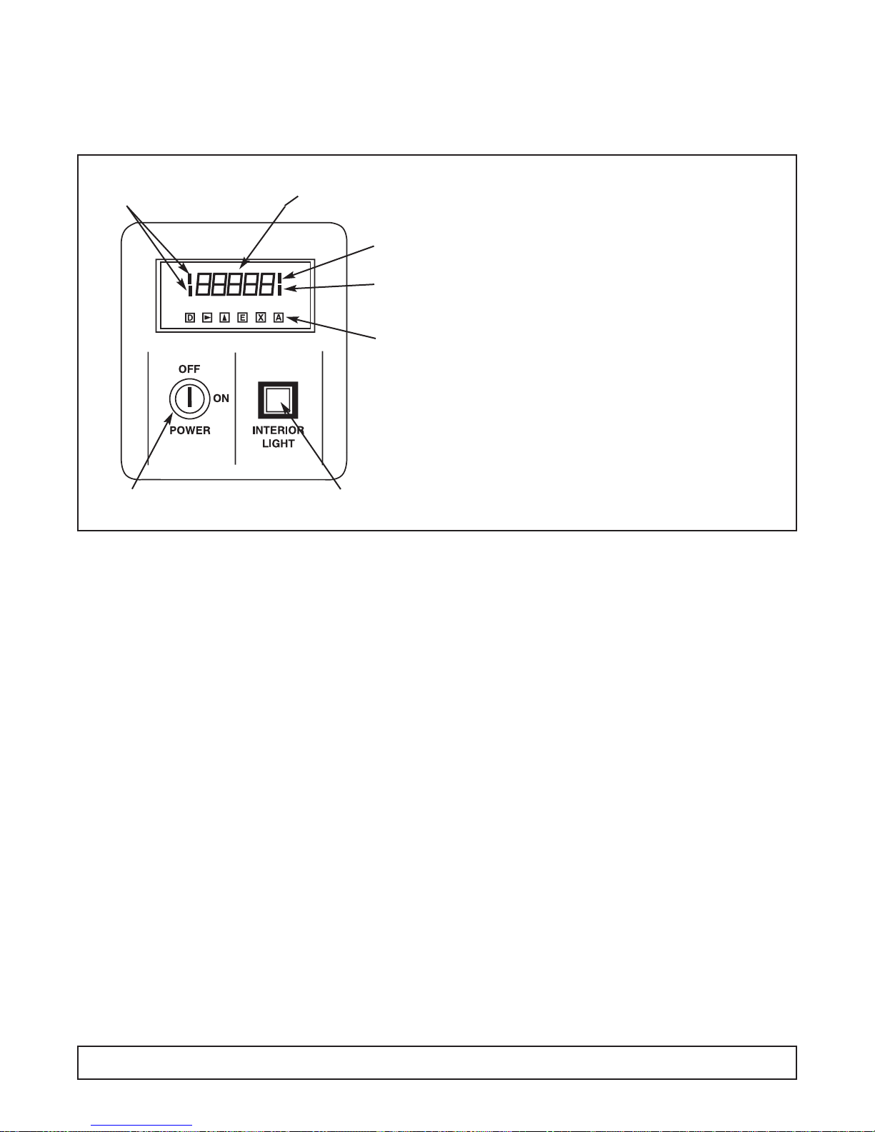
MODULE #1 – DIGITAL DISPLAY
Blood Bank & Incubator Models
Vendor – Analogic
Effective Through June, 2002
GENERAL
This module contains the ON/OFF power switch, interior cabinet light switch and digital meter displaying
cavity temperature.
1. Cabinet power is controlled by a keyed ON/OFF
switch. The key is removable in both positions. In
the OFF position the battery charger and power
failure relay in the optional Alarm System Module
are still energized. CAUTION - Risk of Electrical
Shock. Disconnect Power Before Servicing.
2. Interior cabinet light is controlled by a push button. In
the recessed position, cabinet light is on and the
switch will glow (on glass door cabinet and incubator
only).
3. The digital process meter monitors cavity conditions.
Cabinet temperature is displayed on a g reen v acuum
fluorescent display in degrees centigrade (°C). Four
red status indicators que the attendant of display
mode and temperature alarm conditions. The maximum (peak) temperature and minimum (valley) temperature are saved for instant recall at a later time.
The unit may be provided with alarm relay contacts
for audio, visual and remote signaling from the
optional Alarm System Module. Also a 420 mA
process signal may be incorporated within the unit to
drive an optional circular chart recorder.
SETTING & REVIEWING PARAMETERS
1. In normal mode of operation the instr ument displays
the current temperature reading. By pressing the ‘D’
key, other values and operating parameters may be
sequentially reviewed.While the ‘D’ key is held down
a code indicating the parameter is displayed; when
the key is released, the parameter value is shown
(See Table 1 for par ameters).When these values are
displayed, the two left side red indicator bars are lit,
indicating a non-standard display (See Figure 1).
2. When the desired parameter value is displayed,
press k key to en ter numer ic entr y mode. One digit
will blink (for changing values only).
3. Press the m key to adjust this digit to the desired
value, then press k to select the next digit.
4. When the right most digit is blinking and correct,
press the ‘E’key to store the value and return to normal meter operation.
5. If a mistake is made at any point before the ‘E’key is
pressed, press the ‘X’key to cancel the operation and
return to the default display.
6. The peak or valley values may be reset to the current
display by pressing the ‘E’ key when the value is displayed.
BUTTON FUNCTIONS
DDISPLAY Display next parameters
in order
k RIGHT Make first Digit active.
Then step right one digit.
m UP Increment active digit by one.
E ENTER Enter the displayed value in
parameter memory or reset
peak or valley measurement.
X EXIT Cancel current operation
and display interior cabinet
temperature.
ANOT USED
9-Segment Display
Lit When Not
Showing Cavity
Temperature in °C
Low Temp.
Alarm Indicator
High Temp.
Alarm Indicator
Buttons
Located
Behind Hinged
Access Cover
Cabinet Interior Light Switch
(Glass Door Cabinets & Incubators)
Keyed ON/O FF
Power Switch
82 MODULE #1
FIGURE 1

MODULE #1 – ANALOGIC PARAMETERS
MODULE #1 PARAMETERS 83

MODULE #1 – DIGITAL DISPLAY
Blood Bank & Incubator Models
Vendor – Daytronics
Effective July, 2002 Through Present
84 MODULE #1
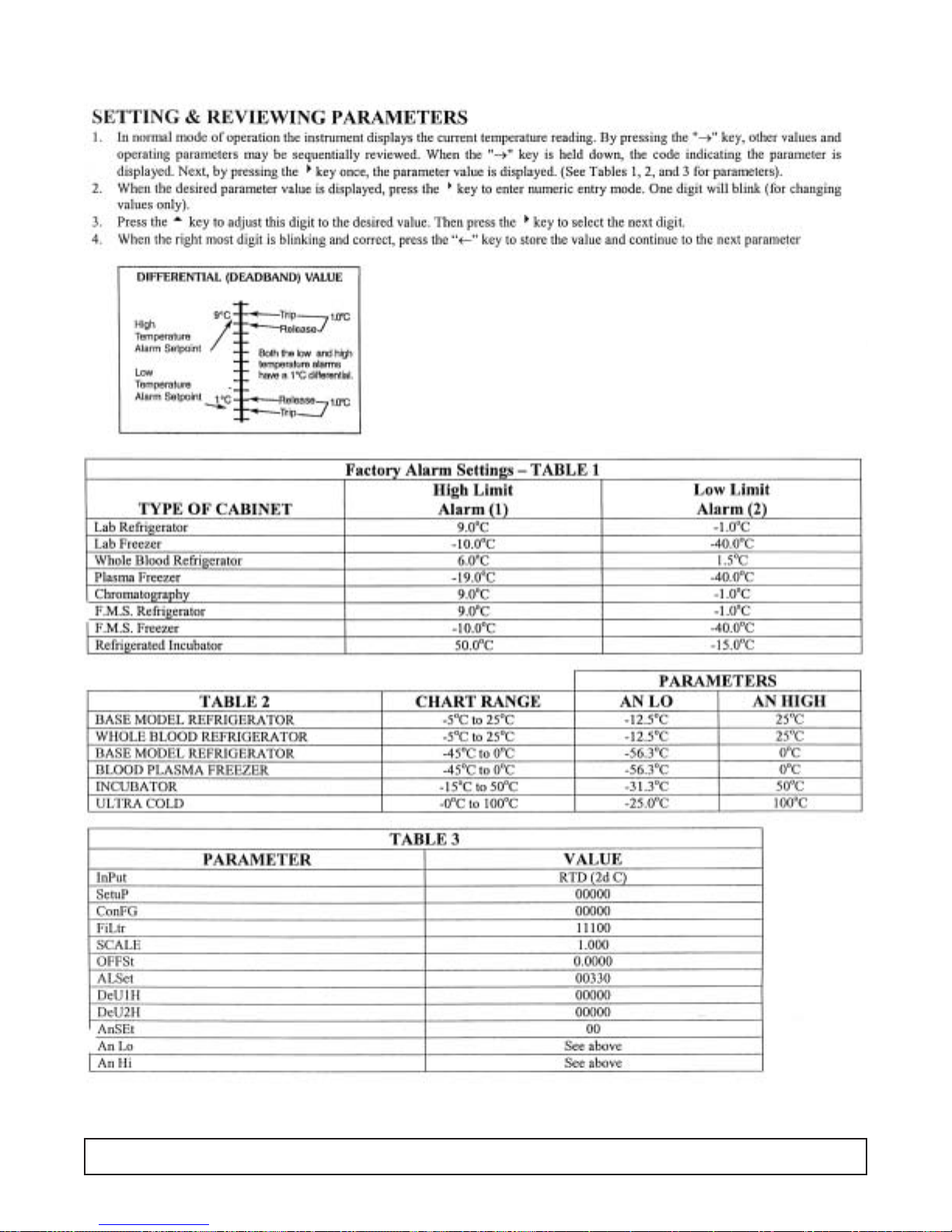
MODULE #1 – DAYTRONICS PARAMETERS
MODULE #1 PARAMETERS 85

OPTIONAL ALARM SYSTEM
GENERAL
This module contains audio and visual alarm signals for
power failure, low and high cavity temperature, plus a
contact for remote alarm connection.
1. A power failure alarm is provided to que the attendant
of interrupted electrical service. This alarm is only
functional when the keyed ON/OFF po wer switch is in
the ON position, and the battery is connected and
properly charged. In a power failure condition all cabinet monitoring and operation ceases.
1. A. A rechargeable battery is provided external to the
communicator panel, when the Alarm System
Module is installed.Connect the red wire coded +
to the positive battery terminal and the pink wire
coded - to the negative.The battery is located in
the compressor compartment.
1. B. Whenever the cabinet is plugged into an electrical
supply the power failure relay and battery charger
will be energized regardless of the key ed ON/OFF
power switch position. This provides continuous
charging of the battery. Caution should be used
when servicing the cabinet.
1. B. CAUTION - Risk of Electrical Shock Disconnect
Power Before Servicing Unit.
2. The temperature alarms indicate to the attendant that
cavity conditions are in excess of either the predetermined low or high temperature limits. These cavity
temperature limit alarms are signalled from the Digital
Display Module and set via the digital process meter.
See Table 1 for f actory settings.T o adjust alarm points
see “Setting and Revie wing Par ameters”under MODULE # 1, DIGITAL DISPLAY.
3. A button is provided for testing proper alarm system
signaling. When depressed the battery is exclusively
used to power all visual alarm indicators, audio alarm
circuit, and relay controlling the remote alarm contact.
This test should be conducted daily to insure functionability and satisfactory battery charge.When testing alarms, visually check to see if lights from “Power
Failure,” “Low Temp.,” and “High Temp.” indicators
come on when button is depressed. A burned out
bulb in an indicator will disable that alarm function.
4. During an alarm situation, the audio portion of the
alarm signal may be silenced by depressing the
“SILENCE” button. If the alarm condition is not corrected within sixty minutes the audio signal will again
be activated.This function has no effect on the visual
signal or remote alarm contact.
5. A normally open alarm contact is provided on the
reverse side of the communicator panel.It is intended for low voltage, N.E.C. Class II wiring only. Upon
an alarm condition the contact closes until the problem, has been corrected.
FACTORY ALARM SETTINGS
LOW HIGH
TYPE OF LIMIT LIMIT
CABINET ALARM ALARM
Lab Refrigerator ——— 9°C
Lab Freezer ——— -10.0°C
Whole Blood Refrigerator 1.5°C 5.5°C
Plasma Freezer -40.0°C -19°C
Refrigerated Incubator -15.0°C 50.0°C
TABLE 1
Visual Alarm Indicators
Alarm Circuit
Test Switch
Timed Audio
Silence Switch
Audio Alarm
86 OPTIONAL ALARM SYSTEM

ALARM SYSTEMS COMPONENTS
Rear Views of an Alarm Module
1 Battery Charger
26 Volt Relay
3 120 Volt Relay
4Silence Indicator Light
5Time Delay Relay
6Test Switch
7High Temp. Indicator
8Low Temp Indicator
9Power Failure
10 Remote Alar m Contacts
11
11
22
22
33
33
77
77
99
99
88
88
44
44
66
66
55
55
Emergency
Procedure Planning:
Post adjacent to, or on the cabinet
door, instructions to follow in the
event of an alarm condition:
1. Persons to be notified and the
telephone numbers of each;
2 The location of other refrigera-
tor/freezers that might have the
space for emergency storage;
3. The telephone numbers to
call for electrical refrigeration
system repair.
111100
00
ALARM SYSTEMS COMPONENTS 87

GENERAL
Incubator cabinets incorporate a proportional electronic
temperature controller.
Cavity temperature is maintained
by the electronic temperature
controller located on the communicator panel. Set control knob
pointer on desired cavity temperature. (See photo at left.)
Cavity temperature may fluctuate slightly with varying ambient temperature.
The photo below shows the rear view of the temperature control module. This module maintains cabinet
temperature by pulsing voltage to a heater located
under the evaporator coil. This module consists of a
solid state controller, solid state relay and a potentiometer. When replacing the solid state relay, make
sure the polarity between the controller and the relay
coil are the same. When the cabinet has reached set
point temperature, the load light indicator on the controller should be blinking on and off.
NOTE: If the cabinet temperature controller is set
below 0°C manual defrost will be necessary.
CAVITY TEMPERATURE CONTROL
Refrigerated Incubator
88 CAVITY TEMPERATURE CONTROL

MODULE #4 – DOOR AJAR/RECEPTACLE SWITCHES
Refrigerators
WHOLE BLOOD REFRIGERATORS –
GENERAL
This type of refrigerator has a panel indicator to que
the attendant of an open cabinet door. The temperature probe is located in a simulated product load within the cavity.
Whenever the cabinet door is open a panel indicator
light is illuminated, when the door closes the light goes
out.
DOOR AJAR
FIGURE 1
MODULE #4 89

WIRING DIAGRAM – Control Panel ST260RIR
Incubator
90 WIRING DIAGRAM
D
REV
CODE
WIRE
DETAIL
X
YELLOW
TYPE
WIRE
RM
=
DATE
:
THK
PE = PURPLE
PK = PINK
GY = GRAY
TN = TAN
YW
BK = BLACK
BE = BLUE
BN = BROWN
WE = WHITE
OE = ORANGE
(64)
IN
WIRE
TERM
IN
LTH
CLR
GA
X
DRAWN
XX
00-C-0017-12
XXX
2-26-96
XX
:
XX
PART NO.
DATE
APPR
DESCRIPTION
DATE
WIRING DIAGRAM (CONTROL PANEL)
CHKD
BLACK 19-A-1054-05
WHITE 19-A-1054-04
*SHIELDED CABLE
19-A-1151-00
70 FUSE 1AMP 19-A-1049-00
71
72
HARNESS
PURPLE LEAD
BLUE LEAD
GREEN LEAD
19-1020-00
BROWN LEAD
ORANGE LEAD
YELLOW LEAD
RED LEAD
(58)
(60)
(59)
18PE008GS2A
18PK008GX2A
18GY008GX2A
WHITE LEAD
BLACK LEAD
*
(56)
(55)
18BN008GS2A
18WE008GS2A
(52)
(53)
(54)
(50)
(51)
18OE008GR2A
18WE004GG2A
18BK004GX2A
18BN008GX2A
18RD008DG2A
(49)
(48)
(47)
(46)
(45)
18PK024SS2A
18OE024SS2A
18YW008AD2A
18BN008AD2A
18BE008AG2A
*
(44)
18RD008GS2A
39
(35)
(34)
(36)
(37)
18BK024GG2A
18WE024GG2A
18BN004GR2A
18GY032SS2A
18BK036GG2A
18WE036GG2A
38
(33)
(30)
(29)
18WE008GQ2A
18BK008GQ2A
BLACK LEAD
WHITE LEAD
18BE008GQ2A
(28)
(27)
(26)
(25)
(24)
18GY008GG2A
18GY012DG2A
18PE008GR2A
18OE004GR2A
18OE008GG2A
(22)
(21)
(20)
(23)
(18)
18RD004QQ2A
RESISTOR W/LEADS
18PE008GQ2A
18PE008GG2A
18PE008DG2A
18YW004GR2A
(13)
(15)
(16)
(14)
(17)
18YW008QR2A
18BN008GR2A
18YW008GR2A
18YW008GQ2A
18GY004GQ2A
(11)
(12)
(10)
(08)
(07)
(09)
18GY016GL2A
18YW020QS2A
18PE020RS2A
18BE020RS2A
18RD004GQ2A
(05)
(06)
(03)
18RD054GQ2A
BLACK LEAD
18PK054GQ2A
18PK016GL2A
18RD020GS2A
GN = GREEN
(02)
WIRE CODE
COLOR CODE
BLACK & WHITE LEAD
18RD008GR2A
123456789101112131415161718192021222324252627282930313233343536373839404142434445464748495051525354555657585960616263646566676869
RD = RED
ITEM NO
CHART RECORDER
37
48
49
NOTE: WHEN CHART RECORDER IS NOT
PRESENT WIRE #48 IS CONNECTED
TO J4/pin3 ON CONTROLLER/MONITOR
AND WIRE #37 IS NOT USED.
LOW VOLTAGE
RACEWAY
PINK
-
5
3
+
BATTERY
RED
TERMINAL
STRIP
4-20mA(+)
CIRCUIT BOARD
CONTROLLER/MONITOR
SENSOR
GND(-)
1
3
J4
44
RTD
ALARM
J5
71
71
72
72
115V
TRANSFORMER
NO
NC
COM
2
7
1
6
J3
4
230V
19-0998-00
19
BUTTON
PUSH TO TEST
C
C
NONCNO
NC
15
RESISTOR
7
11
10
1
6
J2
1
RED
LL
RED
L
RED
1
6
J1
52
HIGH
LOW
POWER
55
15
TEMP.
TEMP.
FAILURE
56
INDICATOR
INDICATOR
INDICATOR
RD
DOOR AJAR
12
BN
WE
YW
19-1004-00
MODULE
GY
TERMINAL
17
TERMINAL
#3
BOARD
16
8
7
BOARD
19
P/N 19-A-1151-00
SHIELDED CABLE ASSEMBLY
44
GROUND
58
58
L
47K
RESISTOR
15
15
BLACK
7
WHITE
6
8
RED
POTENTIOMETER
PE
PK
BN
YW
36
23
36
20
6
5
3
4
2
1
WE
OE BK
33
RELAY
6V ALARM
61
62
64
65
5
9
10
4
11
3
CONTROLLER
2
12
13
1
TEMPERATURE
1
4
21
14
2
3
4
+
-
25
ALARM
33
TERMINAL STRIP
13
13
9
9
12
54
63
RELAY
2
+
SOLID STATE
1
-
47
46
CHARG
E
-
+
D
C
12V
24
8
-
C
RECPTACLE
E
115
AVC
RELAY
+
1
TIME DELAY
22
28
SONALERT
6
432
18
70
32
31
28
TERM. BOARD
27
30
BK OE
WE
29
5
8
C
1
7
ALARM SYSTEM
POWER
115V
RELAY
51
WEBKOE
BNYWRD
INTERIOR
LIGHT
SWITCH
MODULE #1
DIGIT DISPLAY
TO MATING PLUG
3
4
45
44
26
C
NO
MODULE #2
38
FUSE 1.0 AMP
39
53
PE
BE
ON ELECTRICAL
BOX SEE DIAGRAM
22
BUTTON
AUDIO SILENCE
34
35
66
67
69
GROUND
50
POWER
ON/OFF
68
THESE CONNECTIONS ARE MADE IN THE RACEWAY
BE PE
RD
TERMINAL
BOARD
ON PANELS W/ALARM MODULE OPTION.
860
6
59
8
4
6
2
SWITCH
RACEWAY
HIGH VOLTAGE
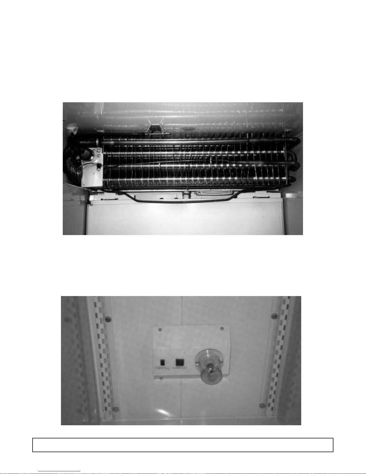
1Evaporator Coil
2Cap Tube (14' x .042)
3Thermodisc
(open 140°F / close 130°F)
4 Heater Calrod
(800 Watts / 16.5 Ohms)
5R.T.D.Temperature Probe
INCUBATOR EVAPORATOR LAYOUT
CABINET INTERIOR LAYOUT
1 Receptacle Box
22 Amp Fuse
3Electrical Outlet
4Incandescent Light
11
33
55
33
22
44
22
44
11
INCUBATOR EVAPORATOR & CABINET INTERIOR LAYOUTS 91
ELECTRICAL/REFRIGERATION SPECS. ST260RIR
Incubator
Compressor HP117-1-3085
Compressor BTUH / -10°F Evap 1777
Recommended Operating Temp. Range 5°F to 122°F (-15°C to 50°C)
Cabinet V olts 115
Expansion Device Capillary .042 x 14'
Charge Refrig.Type / Oz. / Grams R404A / 15 / 425.2
SYSTEM COMPONENTS
AMBIENT 70°F / 21.1°C 80°F / 27°C 90°F / 32.5°C
Cavity Temp. (F / C) 31 / -2 30 / -2 30 / -2
Suction Pressure (PSIG / Kpa) 16 / 200 18 / 213 21 / 213
Discharge Pressure (PSIG / Kpa) 173 / 1068 198 / 1268 227 / 1358
Compressor Amps 2.4 2.6 2.8
Total Refrigeration Amps 10.8 6.1 10.1
SYSTEM PERFORMANCE
92 ELECTRICAL / REFRIGERATION SPECIFICATIONS

TROUBLESHOOTING CHARTS
TROUBLE COMMON CAUSE REMEDY
UNIT WILL NOT RUN.
Blown Fuse. Check power for “live”circuit. If outlet is
“dead” but building has power, replace the
fuse.Try to deter mine the cause of the overload or short circuit
Low Voltage. Check outlet with voltmeter.Should check
115V plus or minus 10%.
If circuit is overloaded, either reduce load or
have electrician install separate circuit.
If unable to remedy any other way, install
auto-transformer.
Open motor or temperature control. Jumper across terminals of control. If unit
runs and connections are all tight, replace
control. Power element may have lost
charge or points may be dirty. Repair or
replace thermostat.
Open relay. Check relay. Replace if necessary.
Open overload. Check overload.Replace if necessary
Open compressor. Check compressor.Replace if necessary.
Open service cord. Check with ohmmeter at unit. If no circuit
and current is indicated at outlet, replace
or repair.
Broken lead to compressors or cold Repair or replace broken leads.
control.
Service cord not plugged in. Plug in cord.
CABINET TOO W ARM.
Thermostat position set too warm, not Turn knob to colder position.
allowing unit to operate often enough.
Fan motor not running. Check and replace fan motor if necessary.
Shortage of refrigerant Check for leaks. Repair, evacuate and
recharge system.
Not enough air circulation around Relocate cabinet or provide clearance to
cabinet. allow sufficient circulation.
Dirty condenser or obstructed Clean the condenser and the ducts.
condenser ducts.
Thermostat control capillary not Refer back to removal/installation
properly installed. instructions detailed in this manual.
TROUBLESHOOTING 93

TROUBLE COMMON CAUSE REMEDY
CABINET RUNS
Not enough air circulation around Relocat e cabinet or provide p roper clearances
CONTINUOUSLY.
cabinet or circulation is restricted. around cabinet.Remove restriction.
Cooling large quantities of product or Explain to customer that heavy loading
heavy loading. causes long running time.
Refrigerant charge undercharged Check, evacuate and recharge with proper
or overcharged. charge.
Room temperature too warm. Ventilate room as much as possible.
Thermostat defective. Check control.If it allows unit to operate all
the time, replace control.
NOISY OPERATION.
Loose flooring or floor not firm. Tighten flooring or brace floor.
Tubing contacting cabinet or other tubing. Move tubing gently!
Cabinet not level. Level cabinet.
Compressor mechanically grounded. Replace compressor mounts.
Fan hitting drain pan or Move fan.
mechanically grounding.
Shipping bands rubbing. Make sure all shipping bands have been cut
and removed.
Loose fan blades or motor. Tighten fan blades and/or motor.
Loose parts or refrigeration or electrical Tighten all loose fittings. Move misplaced
lines out of place. lines.
UNIT CYCLES ON
Short relay. Replace relay
OVERLOAD.
Weak overload protector. Replace overload protector.
Low voltage. Check outlet with voltmeter. Underload voltage
should be 115V plus or minus 10%. Check
for several cabinets on same circuit or
extremely long or underseed cord being used.
Short compressor. Check with meter and also ground before
replacing.
CABINET LIGHTS
Light switch off or defective. Try new bulb or bulbs.Inspect lampholders
WILL NOT WORK.
for signs of bad connections.
COMPRESSOR
Incorrect voltage. Check voltage to compressor terminal
WILL NOT RUN.
board.Voltage must be plus or minus 10% of
nameplate voltage.
94 TROUBLESHOOTING
TROUBLE COMMON CAUSE REMEDY
UNIT RUNS
Abnormally high, heavy use of cabinet. Heavy usage requires more operation
TOO MUCH.
Check usage and correct or explain.
Shortage of refrigerant. Unit must r un Put in the normal charge and check for
longer and will operate at a lower leaks.
than normal suction pressure.
Overcharge of refrigerant.Excess- Remove excess charge.
ively cold or frosted suction liner
results in lost refrigeration effort.
Restricted air flow over condenser Correct the condition.
or air or non-condensable gases
in system.
High room temperature. Check for temperature variance.Correct
condition.
Compressor inefficient. Replace.
Thermostat setting too cold. Raise setting.
UNIT SHORT CYCLES.
Cycling on overload because of high/low Check voltage, head pressure and air
line voltage with variance more or less passages.Repair and correct condition.
than 10% from 115 volts.May also
be caused by head pressures too high.
PRODUCT T OO COLD.
Thermostat set too cold. Set warmer.(Setting #1 is the warmest; #7 is
the coldest.)
Thermostat bulb contact bad. If the bulb contact is bad, the bulb tempera-
ture will lag behind the sleeve temperature,
causing the unit to run longer and make the
cabinet too cold. Make sure bulb makes good
contact with the bulb well.
Room temperature abnormally low. Correct conditions.
PRODUCT T OO WARM.
Thermostat set too warm. Set colder.(setting #1 is the warmest; #7
the coldest.
Thermostat contact points dirty Clean or replace thermostat.
or burned.
Thermostat out of adjustment. Readjust or change thermostat.
Excessive service load or abnormally Educate customer about problems that are
high room temperature. caused by improper loading and excessive
room temperature fluctuations.
Excessive frost accumulation. Defrost the cabinet.
TROUBLESHOOTING 95

COMPRESSOR – TROUBLESHOOTING CHARTS
TROUBLE COMMON CAUSE REMEDY
WON’T START. NO HUM.
Open line circuit. Check wiring, fuses, receptacle.
Protector open. Wait for reset—check current.
Control contacts open. Check control, check pressures.
Open circuit in stator. Replace stator or compressor.
WON’T START. HUMS
Improperly wired. Check wiring against diagram.
INTERMITTENTLY.
(cycling on protector)
Low line voltage. Check main line voltage, determine location of
voltage drop.
Open starting capacitor. Replace star ting capacitor.
Relay contacts not closing. Check by operating manually. Replace relay if
defective.
Open circuit in start winding. Check stator leads.If leads are all right,
replace compressor.
Stator winding grounded (normally Check stator leads. If leads are all right
will blow fuse.) replace compressor.
High discharge pressure. Eliminate cause of excessive pressure.Make
sure discharge shut-off and receiver valves
are open if applicable.
Tight compressor. Check oil level – correct binding condition, if
possible.If not, replace compressor.
Weak starting capacitor or one weak Replace.
capacitor of a set.
COMPRESSOR STARTS –
Low line voltage. Bring up voltage.
MOTOR WON’T GET OFF
ST AR TING WINDING.
Improperly wired. Check wiring against diagram.
Defective relay. Check operation – replace relay if defective.
Running capacitor shorted. Check resistances. Replace capacitor if
defective.
Starting and running windings shorted. Check capacitance – replace if defective.
Starting capacitor weak or one of a Check capacitance.Replace if defective.
set open.
High discharge pressure. Check discharge shutoff valves.
Check pressure.
Tight compressor. Check oil level.Check binding. Replace
compressor if necessary.
96 TROUBLESHOOTING

TROUBLE COMMON CAUSE REMEDY
COMPRESSOR STARTS
Low line voltage. Bring up voltage.
& RUNS BUT CYCLES
ON PROTECTOR.
Additional current passing through Check for added fan motors and pumps
protector. connected to wrong side of protector.
Suction pressure too high. Check compressor for proper application.
Discharge pressure too high. Check ventilation, restrictions and overcharge.
Protector weak. Check current - replace protector if
defective.
Running capacitor defective. Check capacitance. Replace if defective.
Stator partially shor ted or grounded. Check resistances; check for ground. Replace
if defective.
Inadequate motor cooling. Correct cooling system.
Compressor tight. Check oil level.Check for binding condition.
Unbalanced line (three-phase). Check voltage of each phase.If not equal,
correct condition of unbalance.
Discharge valve leaking or broken. Replace valve plate.
STARTING CAPACITORS
Short cycling. Reduce number of starts to 20 or less per
BURNT OUT.
hour.
Prolonged operation on starting Reduce starting load (install crankcase
winding. pressure limit valve), increase voltage if
low – replace relay if defective.
Relay contacts sticking. Clean contacts or replace relay.
Improper relay or incorrect relay setting. Replace relay.
Improper capacitor. Check parts list for proper capacitor rating:
mfd. and voltage.
Capacitor terminals shorted by water. Install capacitors so terminals won’t be wet.
RUNNING CAPACITORS
Excessive line voltage. Reduce line voltage to not over 10% above
BURNT OUT.
rating of motor.
High line voltage and light load. Reduce voltage if over 10% excessive.
Capacitor voltage rating too low. Install capacitors with recommended voltage
rating
Capacitor terminals shorted by water Install capacitors so terminals won’t be wet.
RELAYS BURNT OUT.
Low line voltage. Increase voltage to not less than 10% above
motor rating.
Excessive line voltage. Reduce voltage to not more than 10% above
motor rating.
Incorrect running capacitor. Replace with correct capacitor.
Short cycling. Reduce number of starts per hour.
Relay vibrating. Mount relay rigidly.
Incorrect relay. Use relay recommended for specific motor
compressor.
TROUBLESHOOTING 97

FLUORESCENT LAMP – TROUBLESHOOTING CHARTS
TROUBLE COMMON CAUSE REMEDY
NORMAL END OF LIFE.
Normal failure.Active material on Replace lamp promptly.
Lamp won’t operate.Flashes momen-
cathodes exhausted.
tarily and goes out or blinks on and
off. Ends probably blackened.
SHORT LIFE.
Wrong lamp type used. Replace with lamp type marked in owner’s
manual.
Wrong type of starter. Replace with correct starter.
Ballast not supplying the specified Replace with correct ballast for rating for
electrical values. lamp size.
Wrong type of ballast used. Replace ballast with proper type.
Too low or too high voltage. Check primary voltage with range
specified on ballast name plate.
Poor circuit contact (likely at lamp- Lampholders should be rigidly mounted
holders). and lamp securely seated.
Ballast improperly or incompletely Study ballast label wiring diagram and
connected. check connections.
Too many lamp starts. Average life for most lamps is dependent on
number of starts and hours of operation.
END BLACKENING.
Normal end of life. Replace lamp promptly.
Dense blackening at one end or both,
extending 2"-3" from base.
Mercury deposit – generally within Should evaporate as lamp is operated.
1" of lamp end.
Poor circuit contact likely at the Lampholders should be rigidly mounted
lampholder. and lamp securely seated.
Ballast improperly or incompletely Study ballast wiring instructions and check
connected. connections.
Wrong type lamp used. Replace with correct lamp type.
Wrong type of starter or defective Replace with proper starter.
starter causing on/off blinking or
prolonged flashing at each start.
Ballast installed not supplying the Replace with ballast of correct rating for
specified electrical values. lamp size.
Line voltage too low or too high. Check line voltage with range specified on
ballast plate.
Ballast improperly or incompletely Study ballast label wiring instructions and
connected. check connections.
The manufacturer uses standard fluorescent lamps in ail of its applications. Standard one- and two-lamp ballast
circuits are used.
Replacement lamps should be purchased over the counter from a local electrical wholesaler.
The table below indicates general problems that may be encountered with fluorescent lighting applications, possi-
ble causes, and corrective maintenance suggestions.
98 TROUBLESHOOTING

TROUBLE COMMON CAUSE REMEDY
NO STARTING EFFORT
Open lamp cathode circuit due to If open, circuit is shown by continuity test or
OR SLOW STARTING.
broken cathode, air leak, or by viewing end of bulb against a pinhole
open weld. of light. Replace lamp.
Wrong lamp type used. Replace with lamp type indicated in owner’s
manual.
Starter at end of life. Replace starter.
Starter sluggish. Replace starter.
Ballast installed not supplying the Replace with correct ballast of correct
specified electrical values. rating for lamp size.
Temperature cold air contact to Correct installation of lamp protection
bulb. tubes, or shields to prevent cold air effects.
Circuit voltage. Check voltage and correct if possible.
DECREASED LIGHT
Temperature operation, cold air Properly install jacketed lamps where
OUTPUT. Full illumination of
affects lamp performance. applicable.
bulbs requires correct assembly
of all components of lighting system.
Circuit voltage. Check voltage and correct if possible.
Ballast improperly or incompletely Study ballast label wiring instructions and
connected. check connections.
Dust or dirt on lamp or fixture. Clean.
BLINKING ON/OFF:
Normal failure. Active material on Replace lamp promptly.
Accompanied by shimmering
cathodes exhausted.
effect during “lighted” period.
Possible lamp fault in some lampholders. Replace lamp. Investigate further if
successive lamps blink or flicker during
“lighted” period.
Wrong type of starter or defective starter. Replace with proper starter.
Ballast installed not supplying the Replace with correct ballast with correct
specified electrical circuit. rating for lamp size.
Circuit voltage. Check voltage and correct if possible.
Loose circuit contact. Lampholders should be rigidly mounted and
lamp securely seated.
OVERHEATED BALLAST.
Wrong lamp type used. Replace with correct lamp number located in
owner’s manual.
Wrong ballast used.Wrong voltage Replace ballast.
rating.
Circuit voltage. Check voltage and correct to design
specifications.
Ballast improperly or incompletely Study ballast label. Correct if installed
connected. wrong.
TROUBLESHOOTING 99
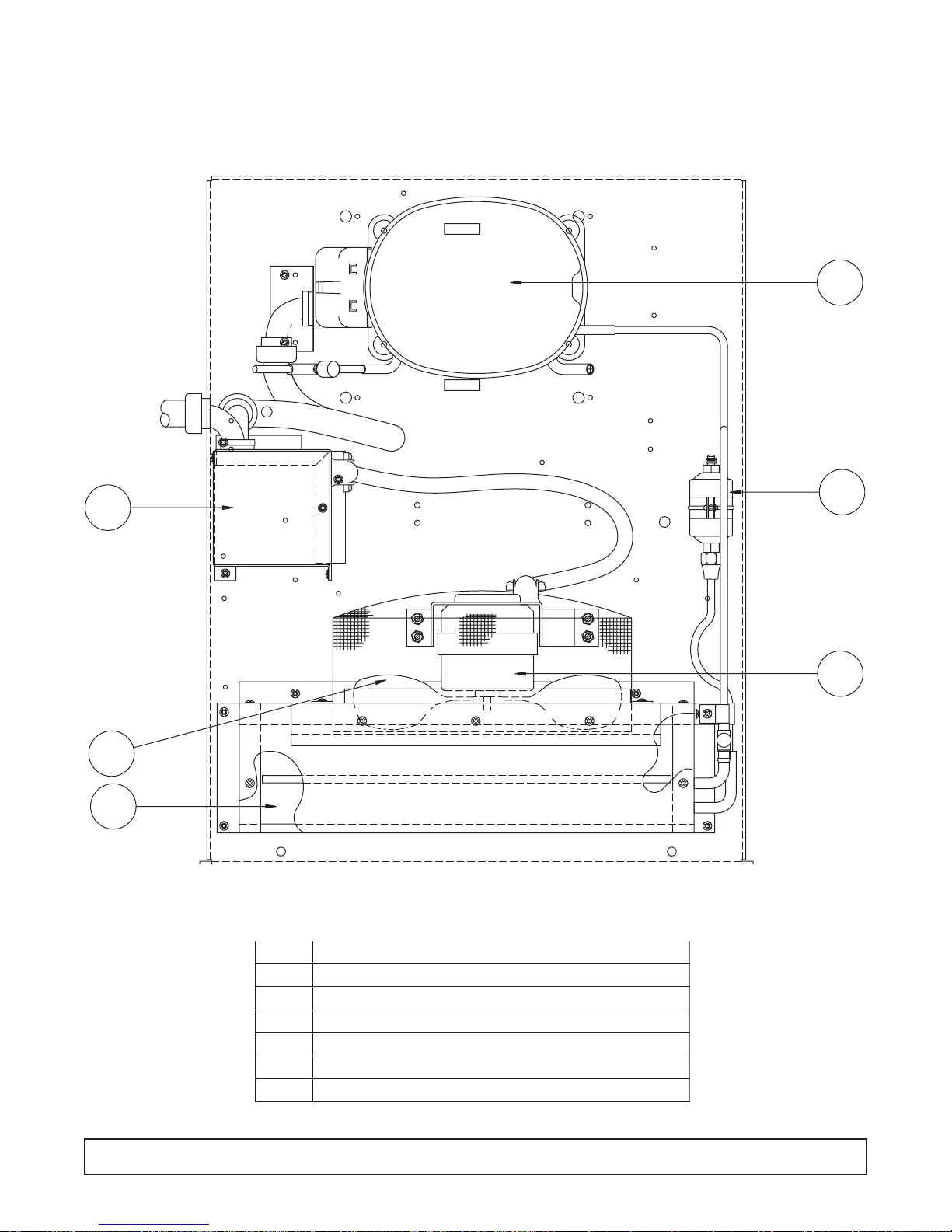
COMPRESSOR AREA MEDIUM TEMP.
Component Identification
100 COMPRESSOR AREA ILLUSTRATION
1
2
4
6
5
3
ITEM
1
2
3
4
5
6
DESCRIPTION
COMPRESSOR
START COMPONENT ASS'Y,
FAN MOTOR
FAN BLADE
FILTER/DRIER
CONDENSER COIL
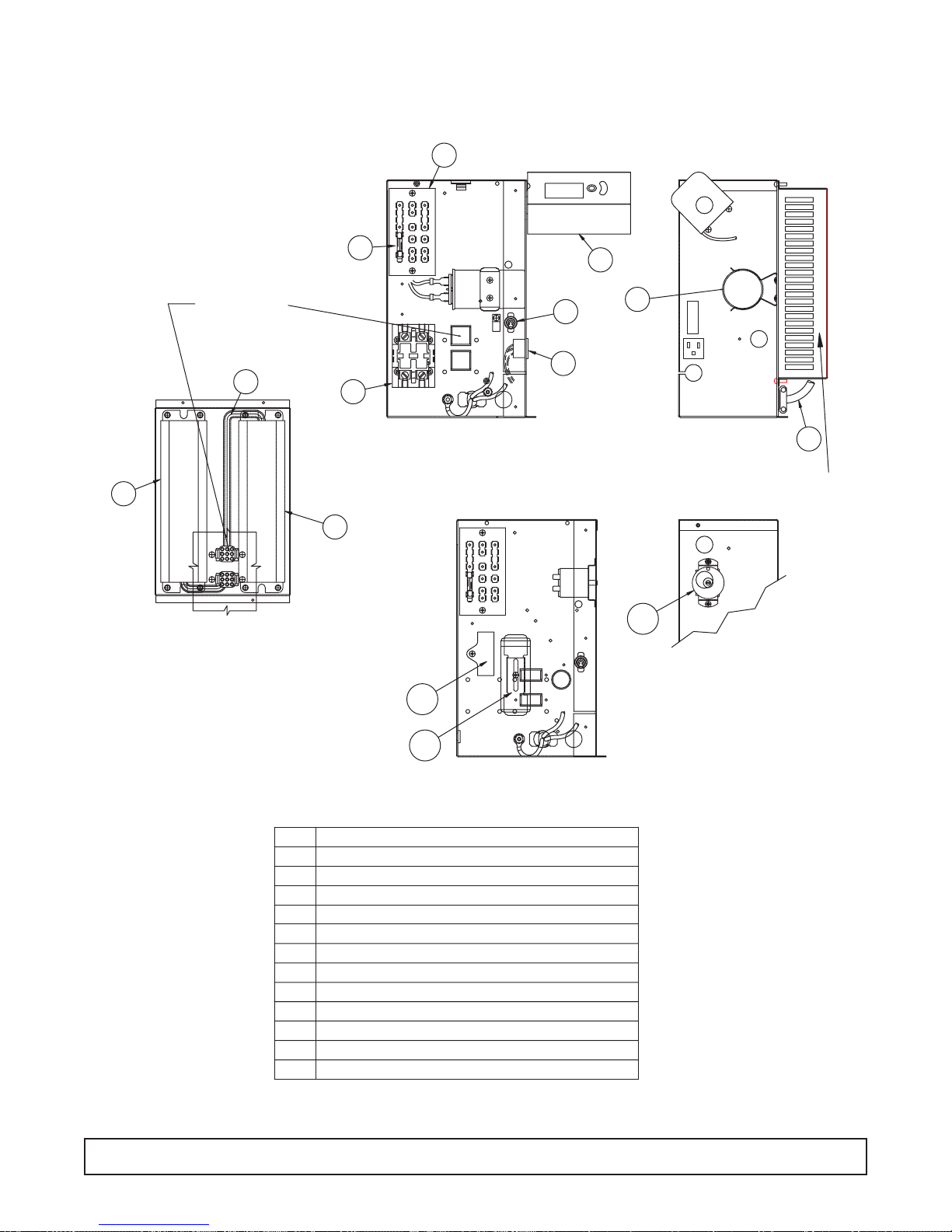
ELECTRICAL BOX ASSEMBLY – (All components shown where applicable)
ELECTRICAL BOX ILLUSTRATION 101
3
BLACK
WHITEYELLOWORANGE
BLUE RED
FUSE
5 AMP-125/250V
PURPLE
BROWN
2
7
HARNESS PLUG FROM
BALLAST, WIRED
FOR ONE LAMP,
MUST BE IN THIS
POSITION
11
ON
T2
T1
L2
L1
OFF
1
5
4
10
REFER TO THIS VIEW FOR
MODELS WITH TIME CLOCK
DEFROST CONTROL
6
LABEL
SIDE VIEW
12
BALLAST ASSY.
SEE DETAIL
6
THIS LOCATION USED
BALLAST BOX
ASSEMBLY
ONLY ON DUAL
BALLAST MODELS
BLACK
FUSE
5 AMP-125/250V
WHITEYELLOWORANGE
BLUE RED
PURPLE
BROWN
2
ON
OFF
6
5
7
OFF
4
3
1
2
THERMOSTAT, CW MODELS
SIDE VIEW
8
9
SEQ
1
2
3
4
5
6
7
8
9
10
11
12
REFER TO THESE VIEWS FOR COLD WALL
AND DUAL TEMPERATURE MODELS
DESCRIPTION
TOGGLE SWITCH, POWER
THERMOSTAT
TERMINAL BOARD
RELAY, POWER (SCIENTIFIC MODELS)
RECEPTACLE
BALLAST
FUSE
RUN CAPACITOR
START CAPACITOR
CAPACITOR, RUN 55 MFD/370 60
HARNESS, BALLAST
POWER CORD

START COMPONENT ASSEMBLY
102 START COMPONENT ILLUSTRATION
2
6
5
4
BLACK WIRE
4
ORANGE JUMPER WIRE
ORANGE WIRE
1
3
ITEM
1
2
3
4
5
6
DESCRIPTION
CAPACITOR, START
CAPACITOR, RUN
RELAY, START
TERMINAL BLOCK
HARNESS, COMPRESSOR
HARNESS, ELECTRICAL BOX
2
1
 Loading...