

OWNER'S MANUAL
FOR BYPASS AND FAN POWERED HUMIDIFIERS
Includes Safety, Operating and Maintenance Instructions
ata!og:0G-HUM-03
Bypass and Fan Powered Humidifiers
Table of Contents
Page
Introduction .................................................... 2
Principle of Operation............................................ 2
Operating Instructions ........................................... 4
Effect of Water Characteristics ................................... 8
Annual Maintenance ............................................. 8
Annual Summer Shutdown ....................................... 8
Periodic Preventative Maintenance ............................... 9
MaintenanceInstructions
Small and Large Bypass Humidifiers ........................... 10
Fan Powered Humidifiers ..................................... 11
Introduction
Thank you for your recent humidifier purchase. We sincerely appreciate your
business and are pleasedto add your nameto our growing list of customers.
Now, please take a few minutes and read this booklet.This will familiarize you
with the benefits you will receive from the equipment you just purchased and
help you understand the routine maintenance that will be required.
I. Prindple of Operation
You have purchased a humidifierthat operates on the evaporative principle.
Itwill providethe proper relative humidity (seeoperating instructions) all during
the heating season. It is very possible that you have questions concerning what
your new humidifier can dofor you, andwhat you should do to receive maximum
benefits from it.This booklet is intended to answer these questions.
Thehumidifieroperatesin conjunctionwith thefurnace blowermotor.When
the humidistatcallsfor humidityandthe blower motorisoperating,water flows
tothe distributionpanlocated atthetop ofthe unit.Thewater is uniformlydis-
tributedacrossthe width ofthe panandthrough ascientificallydesignedsystem
of outlets.It flows bygravityoverthe humidifierpad.Dry,hotairis moved
throughthe moisture-ladenhumidifierpadwhereevaporationtakesplace.The
now-humidifiedair carriesmoistureinvapor formthroughoutthe home.
Thecorrect water flow is determinedby an orifice in each unit.When the
unit is operating,therewill be a small, steadystreamofwater to drain, which
flushesaway mostofthe trouble-causingminerals. Donot use the saddle valve
to regulate the water flow. It is designed to be completely opened or closed.
The minerals and solid residue not trapped by the replaceable humidifier pad
are flushed down the drain. The drain also eliminates the problems caused by
stagnant water. This is the most effective and least expensive methodto dispose
of trouble-causing minerals.
Trouble-free performance and minimum maintenance are assured by the
design features of the humidifier. All unit housing parts that come in contact with
water are non-metal and will never rust or corrode. Neither heat nor water will
affect them under normal operating conditions.
The humidifier pad, designed especially for uniform, high evaporation, and
the Scale Control Insert also efficiently trap mineral deposits which are often the
cause of damage to working parts in ordinary humidifiers. No "white dust" can
be distributed throughout the living quarters. The humidifier pad must be in good
condition to assure high capacity trouble-free performance. It should be
changed annually.
Older design water distribution trays have a granular coating in the bottom of
the distribution tray to provide equal distribution of water to each of the openings
assuring an even flow over the humidifier pad. Do notcleanthe mineral scale off
the bottomofthe water distributiontray at the end ofthe humidificationseason.
If the granular coating is removed, it is not necessary to purchase a new distri-
bution tray. You can accomplish the same uniform performance by applying a
small amount of liquid dishwashing soap over the entire inside surface of the
water distribution tray. This will allow the water to flow evenly through each of
the openings, provided the unit is level, in order to achieve maximum capacity.
The current distribution tray which incorporates a synthetic fabric liner that
replaces the granular coating, is designed to deliver water uniformly over the
entire top surface of the humidifier pad, provided it is mounted level. It is normal
for some mineral deposits to form in the distribution tray as it dries out between
humidification cycles. These deposits can actually help distribute water in the
tray, but if they form enough to block the openings, they should be removed as
described in the "Periodic Preventative Maintenance" section of this manual.
II. Operating Instructions
Your new humidifier is controlled by a manual humidistat, HumidiTracT"or
ThermidistatTM, installed either inthe living area or in the cold air return.
Automatic HumidifierControl:(Manual Humidifier Control- see page 6)
YourHumidiTrac"Control isinstalledinthe coldair return. Duringthe first
heatingseason,yourHumidiTracTM Control needs to beset initiallyto match
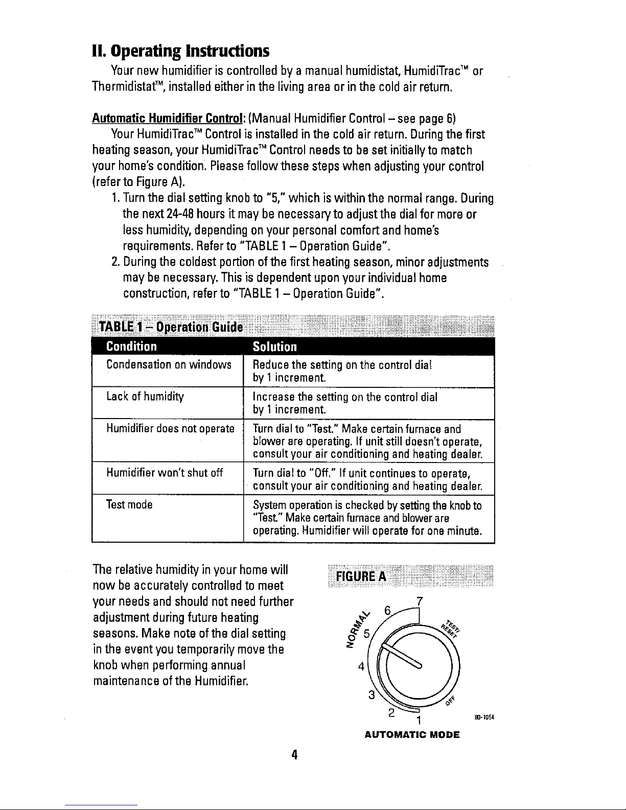
your home'scondition_Pleasefollow these stepswhen adjustingyour control
(referto FigureA).
1.Turnthe dialsettingknobto "5," which iswithinthe normal range. During
the next24-48hoursit maybe necessaryto adjustthe dialformore or
lesshumidity,dependingonyour personalcomfortandhome's
requirements. Referto "TABLE1- Operation Guide".
2. Duringthe coldestportionofthe firstheatingseason, minoradjustments
may be necessary. Thisis dependentuponyour individualhome
construction,refer to "TABLE1-Operation Guide".
Condensation on windows
Lack of humidity
Humidifier doesnot operate
Reduce the setting on the control dial
by I increment.
Increase the setting on the control dial
by 1increment.
Turn dialto "Test." Make certain furnace and
blower are operating. If unit still doesn't operate,
consult your air conditioning and heating dealer.
Humidifier won't shut off Turn dial to "Off." If unit continuesto operate,
consult your air conditioning and heating dealer.
Test mode System operation is checked bysetting the knobto
"Test" Make certain furnace andblower are
operating. Humidifier will operate for one minute.
The relative humidity in your home will
now be accurately controlled to meet
your needs and should not need further
adjustment duringfuture heating
seasons. Make note ofthe dial setting
in the event youtemporarily move the
knob when performing annual
maintenance ofthe Humidifier.
4
4
7
3
2
1
AUTOMATIC MODE
90-1054

YourAutomatic Humidifier, is a high precision system that will accurately
maintain the relative humidity in your home. For every I°F change in outdoor
temperature, the control will automatically adjust the indoor relative humidity
(RH) by 1/2%. If you would like to determine the RHin your home,follow
these steps:
1.Determine the outdoor temperature.
2.Activate the furnace blower by setting your thermostat fan switch to the
"On" position, or setting your thermostat to a higher temperature.
3.Turnthe control dial setting to the "Off" position. Then, slowly turn the
dial clockwise until you hear the solenoid valve "click on." Next, slowly
turn the dial counter-clockwise until you hear the solenoid valve "click
off." At this point, make note of the dial setting.
4. Locateyour dial setting on Table2. Follow the dial setting to the right
until it intersects with the current outdoor temperature. This is the
relative humidity in your home under existing conditions.
5. Returnthe thermostat and the Humidifier Controlto their original settings.
Outdoor Temperature (°F)
-I0 0 10 20 30 40
1 10 10 10 !5 20 25
..... li i
2 10 10 15 20 25 30
3 10 15 20 30 35
4 15 20 25 35 40
_ilii__i_i!i!i__i_i_i__i_o
2 _!_ _ 40 45
20 ..........
6 25 30 35 40 45 45
5
7 30 35 40 45 45 45
As an example, if the outdoor temperature is 20°F,and, following step 3,
the humidifier turns off at "5" onthe dial range, then the RHin your home is35%.
The HumidiTrac" Control will accurately control the humidity in your home
to a maximum of 45% RHand a minimum of 10%RH.Thevalues of outdoor
temperature and dial settings may fall in between or outside of the listed
values in Table 2.In these cases, you can only approximate your home's actual
indoor RH.
5

Tocheck the humidifier's operation, note the current setting and set the
HumidiTracTM Control to the test mode when the furnace blower motor is
operating. Water will flow into the humidifier for 1minute and then itwill turn
off.This insures the unit is operating properly. Donot leave the control in the
test mode as it will not operate. Resetthe control to it's original setting.
Manual Humidistator HumidiTracTM in Manual Mode:(AutomaticHumidifier
Control - see page 4)
Yournew Humidifier is controlled by a humidifier control installedeither in
the living area (typically near the thermostat) or in the cold air return. It is
important to anticipate a drop in outdoor temperature and reduce the setting
accordinglyto avoid excessive condensation. Forexample, with an outdoor
temperature of 20°Fthe correct setting will be 35%relative humidity. If the
temperature is expected to fall to O°F'_hatevening, then merely reduce the
setting to 25%several hours prior to the temperature change.
The recommended settings on the humidifier control are based onyears of
research (seeTable 3)and experience as to what is best for the average
home.These settings represent a compromise between RHlevels that would
be most desirable for comfort reasons and humidity levels that are suitable for
protection of your home. For example, a wintertime indoor RH of 50%may be
considered ideal by some, but unfortunately, it probably would result in
damageto your home. Observance ofthe recommended RHlevels onyour
humidistat, therefore, is an important safeguard. Condensation of water on
inside windows in the form of fogging or frost is usually an indication of too
high relative humidities. This same condensation can take place in other areas
in your home with the possibility of damage resulting.
+40OF.
+30°F
+20°F
+IO°F
O°F
-lO°F
-20°F
45%
40%
35%
30%
25%
2O%
15%
The Humidifier Control is a precision instrument that can be usedto
determine the RHaccurately inyour home duringthe winter. Turn the dial to the
lower setting, then reverse the dial direction slowly until a "click" is heard. At
this point, read the RH onthe dial. This will bevery close to the actual RHin
your home.

Tocheckthe humidifieroperation,setthe humidifiercontrolabovethe
click point,makesurethat thewater saddlevalveis openandthat thereis
electricityto the unit.Generally,the furnaceandblower motormustbeoperat-
ingfor the humidifiercontrolto function.After thehumidifierhasoperatedfor
severalminutesandwater is enteringthe unitandcomingoutatthe drain,
reducethe humidifiercontrolsettingbelowtheclick pointandtheunitshould
automaticallyshutoff. Nowsetthe humidistatdialatthe recommendedinside
relativehumidity,dependingonthe outsidetemperature.Followthe suggested
settingspriorto a dropinthe outsidetemperature.
Additional Information
Be sureto keep fireplace dampers closed when not in use. They provide
an excellent escape route for heat, as well as humidity. Humidity is lost at an
even faster rate than heat because water vapor tends to seek its own level
and your humidifier would not be able to replace it even when running atfull
capacity.
Onoccasion, indoor moisture producing activities such as clothes drying,
cooking, showers, etc., mayraise the relative humidity level higher than it
should be,even though the Humidifier is not operating. Telltale indications,
again, are condensation or frost on cold surfaces such aswindows, doors,
walls, etc. If such condensation persists for several hours, your home should
be ventilated to dissipate the potentially damaging excess moisture.
7

III. Effectof Water L'haracteristics
Your humidifier will operate effectively using either hard or mechanically
softened water.
Any type of water (hard, soft, hot, or cold) is acceptable for usewith the
drain-type humidifiers. Hot supply water, 140° maximum, is recommended for
all heat pump applications.The useof hotsupplywater will also increasethe
amountof humiditygeneratedin otherapplications.The heat inthe water
increasesevaporationandthe water goingtothe drainis coldto thetouch. For
better performanceit is recommendedthat soft(reducedminerals)orfiltered
water be suppliedtothe humidifierpad. Thiscanhelpreduce the amountof
scale andmineraldepositsthat canaccumulateonthe pad.
IV.Annual Maintenance
Forbestperformance,we recommendthat youreplacethe humidiferpad
in your humidifierannually.
• Call the installerof your humidifier. This information is often found on your
equipment.
V.Annual Summer Shutdown
FORTHE SUMMER HUMIDIFIERSHUTDOWN,SIMPLYTURNTHE
HUMIDISTATCONTROLTO THE "OFF"SETTINGAND CLOSETHEDAMPERIN
THEBYPASSHUMIDIFIER.(TURNDAMPERHANDLETO"SUMMER" POSITION)
8

VI. PeriodicPreventativeMaintenance
NOTE: Periodic inspection and preventative maintenance of your total heat-
ing system is important for efficient and safe operation. Your dealer will include
humidifier service during a maintenance inspection.
Your humidifier is equipped with an in-line water strainer and orifice as
shown below. These parts should be inspected and cleaned periodically to
assure continued proper unit performance.
- UTLET
COMPRESSION
NUT
ORIFICE
_ OLENOID
VALVE
INLET
INLET
InspectionandServiceInstructions
1. Disconnectelectrical powerto thefurnaceandshutoff
water supply.
2. Disconnectthe waterline atthe inletfitting.
3. Removethe in-linestrainerfrom insidethe inlet fitting by
usinga smallnail or wire.
4.Flushthein-line strainerto clean it. If it isnecessary
toreplacethe strainer,contact your dealerfor a
replacement.
5.Disconnectthewater lineat theoutletfitting.
6.Inspectplasticfeedtubeby gentlyflexing it andlooking
for cracks orsignsofwear.Replacetubeif it is cracked,
brittle,or has beendamaged.
7.Removethe orificefromthe copperor plastic tube and
makesurethis smallopeningis unplugged.
8.Replacethe orifice andreconnecttheoutletwater line
(DoubleWrenchToPreventLeakingAndValveDamage).
9.Replacethe inlinestrainerandreconnectthe inletwater line (DoubleWrenchTo
PreventLeakingAndValveDamage),
10.Inspect the drain hose to make sure it has a constant downward slope and is
not flattened or blocked. Flexthe hose to loosen any mineral deposits or
blockage. Flush it with water under pressure to remove any debris.
11.Turnonwater supplyandreconnectelectricalpowerto thefurnace.

90-Bla
1. FrontCover
2. FeedTube
3. Nozzle
4. EvaporativeAssembly
5. DistributionTray
a. "V" Notches
7. HumidifierPad
8. Scale Control Insert
9. Drain Hose
10.BypassDamper
CAUTION]Suddenoperationmay cause personalinjuryorproperty
Turnhumidistatto "OFF"beforeservicing.
1.
,
,
.
damage.
Note humidistat settingandturn
humidistattothe "OFF"position.
Atthe sideofthe unitoppositethe
airflowduct,pull front cover(1)off
holdingwith bothhandsandset aside.
Carefullypullthe feedtube(2)out of
the nozzle(3)atthe topof the
evaporativeassembly(4).Pullthis
assemblyout by graspingattop and
tippingout.
Removethe blackdistributiontray(5)
from the evaporativeassemblyby
unsnappingthewhite plasticendsof
the ScaleControl Insert(8),from the
tabsatthe endofthe tray. Followthe
instructions belowdependingupon
thetypeof distributiontrayinyour
humidifier:
Fortrayswith asvntheticfabric liner:
Lightlyscrapeout or brushoffany
mineral deposits,beingcarefulnotto
stretchor loosenthe syntheticfabric
liner.Soakingthetrayinvinegaror a
lime-removingagentis helpfulwhen
tryingtoremovestubbornmineral
deposits,
Fortravswith aranular coatina:Donot
scrapeoffthe granularcoating,but
lightly scrapeout anymineraldeposits
andcleanthe "V"notches (6).This
texturedsurfacehelps ensureeven
waterflow for maximumperformance.
Ifthe granularcoatinghas been
removed,placeseveraldropsof liquid
dishwashingsoapon thedistribution
tray.Thiswillonlyneedto bedone
once ifthere is no granularcoating.
5. Slidethe humidifier pad(7)outfrom the
plasticScaleControl Insert18).Cleanthe insert
frame bytwistingandflexing it toloosenthe
calciumdeposits,or usea putty knife.Replacethe
humidifier pad (PartNo. Pl10-1045for Small
BypassHumidifierand Part No. Pl10-3545for Large
BypassHumidifier)andslidethe padbackintothe
scalecontrolinsertframewith colormark up. Snap
the blackdistributiontray (5)backintoplace.
6. Inspectplasticfeedtubebygentlyflexing itand
lookingfor cracksor signsofwear. Replacetube if
itis cracked,brittle,orhasbeendamaged.
7. Reinstallthe evaporativeassemblyintothe unitby
fitting itsdraintubeintothe roundreceptacleatthe
baseof theunit.Pushthe assemblyinat thetop
againstthebeveledtabsthatwill holditinplace.
Pushthe endofthefeed tubebackfirmly intothe
nozzleandreplace thefront cover.
8. Removethedrainhose(9)from thebottomofthe
unitandbendandflex itto loosenthe internal
calciumdeposits.Thenflush it withwater under
pressureandslipit backontotheblackdrainfitting.
Makesurethedrainhose hasa constant
downwardslopeandisnot flattened orblocked.
9. Checksystemoperation:
ManualHumidistat:Withthefurnace blower
operatingandthe furnace callingfor heat,turnup
Humidistatandchecksystemoperation.
HumidiTracTM HumidifierControl:(Automaticor
Manual)ChecksystemoperationandresetChange
HumidifierPadindicatorbysettingthe knobto
"Test/Reset".Withfurnacebloweroperatingand
furnace callingforheat,humidifierwilloperatefor
one minute.DONOTLEAVEINTESTMODEAS
HUMIDIFIERWILLNOTOPERATE.
10.
SetManualHumidistatDrHumid_racTM Humidifier
Controlto itsoriginalposition.
10

1. FrontCover
2. Base
3. EvaporativeAssembly
4. DistributionTray
5. "V" Notches
6. HumidifierPad
7. Scale ControlInsert
8. Drain Hose
9. Power Cord
90-858
WARNING! 120VOLTSmaycauseseriousinjuryfromelectrical shock.Disconnectpower and
shutoffwater supplybeforeservicing.
1. Notehumidistatsettingandturnhumidistat
tothe"OFF"position.
2. Disconnectelectricalpowerandturnoff
watersupply.
3. Unlatchhumidifiercoverassembly(1)from
baseassembly(2)atthe bottomof the
cover,lift,andsetaside.
4. Pullouttheevaporativeassembly(3)by
graspingatthetopandtippingout.
5. Removethe blackdistributiontray(4)from
theevaporativeassemblybyunsnapping
thewhiteplasticendsofthe ScaleControl
Insert(7),fromthetabsattheendofthe
tray.Followthe instructionsbelow
dependinguponthetypeof distributiontray
inyourhumidifier:
FOrtrayswitha svntheticfabric liner:
LightJyscrapeoutor brushoffanymineral
deposits,beingcarefulnotto stretch or
loosenthesyntheticfabric liner.Soaking
thetray invinegaror alime-removing
agentishelpfulwhentryingtoremove
stubbornmineraldeposits.
Fortrayswithgranular coatinu:Donot
scrapeoffthe granularcoating,butlightly
scrapeoutanymineraldepositsandclean
the"V"notches(5).Thistexturedsurface
helpsensureevenwaterflowformaximum
performance.Ifthe granularcoatinghas
beenremoved,placeseveraldropsof
liquiddishwashingsoapon the distribution
tray.Thiswillonlyneedto bedoneonceif
thereisnogranularcoating.
6. Slidethe humidifierpad(6)outfromthe plastic
ScaleControlInsert(7).Cleanthe insert frameby twisting
andflexingitto loosenthe calciumdepos_ oruse a
puttyknife.Replacethe humidifierpad (PartNo.
P110-3545)backintothe ScaleControlInsertwith the
coloredspot upandsnapthe black distributiontray (4)
backinto place.
7. Reinstalltheevaporativeassembly(3)intothebase
assembly(2).Pushthe evaporativeassembly(3)in atthe
top betweenthe retainingribsthatholdthe assemblyin
placeinavertical position.
8. Removethe drainhose(8)fromthe bottomofthe unit.
Bendandflex it to loosenthe internalcalciumdeposits.
Thenflush it with water underpressureandslip it back
ontothe drain fitting. Makesure the drain hosehasa
constantdownward slope andis notflattened orblocked.
9. Reinstallcover assembly(1)by hookingatthe top of base
assembly(2)andlatchingatthe bottom.
10.Reconnectelectrical power (9)andturn onwater supply,
1t. Checksystemoperation:
Manual Humidistat:With thefurnace blower operating
andthefurnace callingfor heat,turn up Humidistatand
checksystemoperation.
Humid_racTM HumidifierControl:(AutomaticDrManual)
Checksystemoperationand resetChangeHumidifier
Padindicator by settingtheknobto "Test/Reset".With
furnace bloweroperatingandfurnace callingfor heat,
humidifierwill operate for one minute.DONOTLEAVEIN
TESTMODEAS HUMIDIFIERWILL NOTOPERATE.
12.SatManual Humidistator HumidiTracTM Humidifier
Controlto itsoriginal position.
11

c::
€:
c::
€:
c::
<::
<=
€
C:
€
x::
€
,¢=
<:
CAC / BDP
c.,_c_op
Conaun-alr
ModelNo UnitSori_ No
Dat_oHn_ InSt_hadby,
Narr_ ofOwr_r
FOR SERVICE OR REPAIR t FOLLOW THESE STEPS IN ORDER:
f_RST: Cem_ thn_4afle_ YomJm_" gM hl _ O__ pr_ _" Ulyour
U_I Mar_aL Jfhis narnab noHuw_, calf_u_ buldar if
_Jm )e= n_w _md_cl_
SECOND: C_'da_ the_e_est dist_butm',(S_ ",_l_g _iow i_ I
"IHLRD: Co_
Conau_ rRl_ltm_s
_;y_Jse. N_ "t_fk 1_221
Dat_ ol _nstal_t _n
Address ¢4 Instala_on
HUMIDIFIER
L|MITED WARRANTY
UM_TED F_/E-y f.AR W_T_s C_CJBDP It t_l_l_ a_l_ r_nod ALL WORK _NDER THE "pERM$ OF "rl_s W_RFI_NTy _I_ALL B E
1o _ "_OMPAN_P1 ptod_c_ _ _m_ted _ bl fle_h_r_ _ts m _t_tm_ P_RFORMED DU_IWG NORMA_ WORFJN(I HOURB. ALL
_nd w_d_rdl_',_ u_dm, n_rr_t u_ _m;_ _nh_r_r_ for e _iod of ft_ RIEpLAc'f_MENT PARrT_ W_ET_F._R N_W DR _REM_UFACTURED
y_f_ fio_ _1_ d/l_ of _r_ iftStlllt_% _he_lel _1 P_ _c_d _ _i.S_UME AST_E3R WARRAI_I_ P_RIo_ ONLYTHE R_M_FINGTtM_
_ ¢_ _ _. A mm ot nm_t_u_tumd pad, at _ COMP._Ny_ pERIOD OF _ WARR_NT_/.
_, _ m_lc_ ir_ _ pal, _11 bl FmV_d _ ¢ha_
t_r thi p&lf R_lf: PROV_ED th_ _lf_cd._ par; I_ returned _ our THEr._t_e_Wl_L't_TI_NItI_Of*lla_.EF_R_
T_S W_RRANTY OO£S NOT INCLUDE LABOR OR OTHER COATI
b_ _ov_d by B s,p_mie _,arran_ o_ _"t_i_/m_4 F_did by 11"4
UM_TATIONS OF WA_I_ClES_LL I_PLI_D WARRANTieS
INCLU_N_ iMPU_O WARRANTIES OF MERCH&NT_8_LITY AND
_:lTN_g5 FOR A pARTICULAR PURPOSE} ARE HEREBY LIMITED
I_RATIONTOTH_p_F;ROD FORW_ICHTHE UMJTEO W_C=,,_N'TY I$
GtV_ AND APPlIES, SOME STKffES DO NOT ALLOW UMITATtOP¢5 ON
LONG AN IMpLIeD WARRANTy _/_TB, SO TH_ ABOVE
_JMITATI_$ MAY rIOT APPLYTOYOU, THE EXPRESSW;_qRM_)E5
MADE _ TH_S WAR RATTY AR_ _XGLL_ W_ AND MAY NOT BE ALTERED,
ENLARGED, OR CHANGE D 8Y ANY D4$TRr_UTOR, D£ALER.OR OTHS R
PERSOt4 WHAT_I:t
'THIs W_r;_NT_ DOE_ NOT COVE_ _UMI_tFIE_ WATER PADS,
m.
CI/,L 0_ Q_"_Ny NM_t_E Wl_TgQEV,TR _ m_es _w ._ aF_,_ ,_
©2005CAC/BDP
7310West Morris St.,Indianapolis,IN 46231
1000672011,05 Form/Catalog:OG-HUM-03
B2203903A
 Loading...