

Page 1
AUTOMATIC HOME STANDBY GENERATORS
Turn to the Experts"
Installation
Guide
This Installation Guide is intended to be
used in conjunction with the Owner’s
Manual.
The Owner’s Manual must first be read
thoroughly prior to installation of the Home
Standby generator.
A Intended for outdoor installation only.
A Not intended for life support
applications.
cvVUus
umn
www.carrier.com
Page 2
Turn to the Experts”
ELECTRICAL INTERCONNECTION DRAWING
Page 3
Page 4

PLEASE NOTE: This installation guide is not a substitute for
the “Owner's Manual” included with this system. Please read
all information prior to installation and operation of your
CARRIER Home Standby Generator.
Thank you for purchasing this tnodei of the CARRIER product line. This
model Is a compact, high performance, air-cooled, engine-driven generator
designed to automatically supply electrical povierto operate critical loads
during a utility power failure.
This unit is tactory installed in an all-weather, acoustical metal enclosure
that is intended
operate using either liquid propane gas (LPG) or natural gas (NG).
exclusively for outdoor installation.
This generator will
READ THIS MANUAL THOROUGHLY
It you do not understand any portion of this manual, contact CARRIER at
1-877-600-2792.
Study these
servicing this equipment. Become familiar with this Installation Guide and
the
operate safely, efficiently and reliably only if it is properly installed,
operated and maintained. Many accidents are caused by failing to follow
simple and fundamental rules or precautions.
CARRIER cannot possibly anticipate every possible circumstance that might
involve a hazard. The warnings in this manual, and on tags and decals affixed
to the unit are, therefore, not all-inclusive. If you use a procedure, work method
or operating technique not specifically recommended, you must satisfy
yourself that it is safe for you and others. You also must make sure the
procedure, work method or operating technique that you choose does not
render the generator unsafe.
The product contains or emits chemicals known to the state of
California to cause cancer, birth defects or other reproductive
harm.
Installation & Owner’s Manual\ncMei
Despite the safe design of this generator, operating this
Throughout this publication, and on tags and decals affixed to the
generator,
you to special instruction about a particular operation that may be
hazardous it performed incorrectly or carelessly. Observe them carefully.
Their definitions are as follows:
DANGER, WARNING, CAUTION
and
NOTE
blocks are used to alert
After this heading, you can read instructions that, if not strictly
A
DANGER
complied with, will result in serious personal injury, severe
property damage and/or without limitation, death.
After this heading, you can read instructions that, if not strictly
A
WARNING
complied with, may result in serious personal injury and/or
severe property damage.
After this heading, you can read instructions that, if not strictly
A
CAUTION
complied with, could result In damage to equipment and/or
property.
A
DANGER
equipment imprudently, neglecting its maintenance or being
careless can cause possible injury or death. Permit only
responsible and capable persons to operate or maintain this equipment.
^ Potentially lethal voltages are generated by these machines.
Ensure all steps are taken to render the machine safe before
attempfing to work on the generator.
A Parts of fhe generator are rotating and/or hot during operation.
Exercise care near running generators.
For safety reasons, CARRIER recommends that the installation, initial start
up and maintenance of this equipment is carried out by a Dealer.
• The engine exhaust fumes contain carbon monoxide, which can be
DEADLY.
NOTE: After this heading, you can read explanatory statements that require
special emphasis.
These safety warnings cannot eliminate the hazards that they indicate.
Common sense and strict compliance with the special instructions while
performing the service are essential to preventing accidents.
Four commonly used safety symbols accompany the
CAUTION
blocks. The type of information each indicates follows:
DANGER, WARNING
and
A This symbol points out Important safety information that, if not
followed, could endanger personal safety and/or property of you
and others.
can cause unconsciousness or even death. This exhaust system is tactory
installed, in strict compliance with applicable codes and standards. You
must do nothing that might render the system unsafe or in
noncompliance with such codes and standards.
• Keep hands, feet, clothing, etc., away from drive belts, tans, and other
moving or hot parts. Never remove any drive belt or tan guard while the
unit is operating.
• Adequate, unobstructed flow of cooling and ventilating air is critical to
correct generator operation. Do not alter the installation or permit even
partial blockage of ventilation provisions, as this can seriously affect safe
operation of the generator.
SAFETY RULES
carefully before installing, operating or
with the unit. The generator can
A GENERAL HAZARD A
This dangerous gas, if breathed in sufficient concentrations,
The generator MUST be installed outdoors.
^ This symbol points out potential explosion hazard.
^ This symbol points out potential fire hazard.
This symbol points out potential electrical shock hazard.
^ SAVE THESE INSTRUCTIONS - The manufacturer suggests that these
rules for safe operation be copied and posted near the unit’s
installation site. Safety should be stressed to all operators and
potential operators of this equipment.
The engine exhaust from this product contains chemicais known
to the state of California to cause cancer, birth defects or other
reproductive harm.
• When working on this equipment, remain alert at all times. Never work on
the equipment when you are physically or mentally fatigued.
• Inspect the generator regularly, and contact your nearest CARRIER
Dealer for parts needing repair or replacement.
• Before performing any maintenance on the generator, disconnect its
battery cables to prevent accidental start up. Disconnect the cable from
the battery post indicated by a NEGATIVE, NEG or (-) first. Reconnect that
cable last.
Page 5

Never use the generator or any of its parts as a step. Stepping on the unit
can stress and break parts, and may result in dangerous operating
conditions from leaking exhaust gases, fuel leakage, oil leakage, etc.
A
ELECTRICAL HAZARD
All generators covered by this manual produce dangerous electrical
voltages and can cause fatal electrical shock. Utility power delivers
extremely high and dangerous voltages to the transfer switch as does
the standby generator when it is in operation. Avoid contact with bare
wires, terminals, connections, etc., while the unit is running. Ensure all
appropriate covers, guards and barriers are in place before operating
the generator. If you must work around an operating unit, stand on an
insulated, dry surface to reduce shock hazard.
Do not handle any kind of electrical device while standing in water,
while barefoot, or while hands or feet are wet.
A
DANGEROUS ELECTRICAL
SHOCK MAY RESULT.
The National Electrical Code (NEC) requires the frame and external
electrically conductive parts of the generator to be connected to an
approved earth ground. Local electrical codes also may require proper
grounding of the generator electrical system.
After the home standby electrical system has been installed it will be
capable of cranking and starting at any time while in the "Auto" mode.
When the unit starts in "Auto” the load circuits are transferred to the
STANDBY (generator) power source. To prevent possible injury when working
on the system
"OFF”, remove control panel fuses and disconnect the starting battery.
always
set the generator’s Auto/Off/Manual switch to its
A
EXPLOSION HAZARDS
• Do not smoke around the generator. Wipe up any fuel or oil spills
immediately. Ensure that no combustible materials are left in the
generator compartment, or on or near the generator, as
EXPLDSIDN
and free from debris.
• Gaseous fluids such as natural gas and liquid propane (LP) gas are
extremely
applicable fuel-gas codes. Before placing the home standby electric
system into service, fuel system lines must be properly purged and leak
tested according to applicable code. After installation, you must inspect
the fuel system periodically for leaks. No leakage is permitted.
may result. Keep the area surrounding the generator clean
EXPLOSIVE.
Install the fuel supply system according to
A
FIRE
PRE-PACKAGED COMPONENTS INCLUDES;
or
In case of accident caused by electric shock, immediately shut down the
source of electrical power. If this is not possible, attempt to tree the
victim from the live conductor.
Use a non-conducting implement, such as a rope or board, to free the
victim from the live conductor. If the victim is unconscious, apply first aid
and get immediate medical help.
Never wear jewelry when working on this equipment. Jewelry can
conduct electricity resulting in electric shock, or may get caught in
moving components causing injury.
For fire safety, the generator must be installed and maintained properly.
Installation always must comply with applicable codes, standards, laws
and regulations. Adhere strictly to local, state and national electrical and
building codes. Comply with regulations the Occupational Safety and
Health Administration (OSHA) has established. Also, ensure that the
generator is installed in accordance with the manufacturer’s instructions
and recommendations. Following proper installation, do nothing that
might alter a safe installation and render the unit in noncompliance with
the aforementioned codes, standards, laws and regulations.
Keep a fire extinguisher near the generator at all times. Extinguishers
rated “ABC” by the National Fire Protection Association are appropriate
for use on the standby electric system. Keep the extinguisher properly
charged and be familiar with its use. It you have any question pertaining
to fire extinguishers, consult your local fire department.
AVOID DIRECT CONTACT WITH THE VICTIM.
A
FIRE HAZARDS
A
A.
CARRIER Home Standby Generator
B.
Outdoor connection box pre-wired to
generator controls and main line circuit
breaker.
C.
30’ pre-w'ired flexible conduit for
hook-up to outdoor connection box.
D.
Automatic transfer switch with built-in
load center.
E.
2' pre-wired conduit for easy connection
to the main electrical
distribution panel.
F.
Flexible fuel line for
.. c.onne.ctiDn.fromjigid gas
j ■■.pipeto/gerierafdf^fuekinl.et
iG:. j Gotripos.ite; mounting, pad
ietirrirnates the jneed: tolpbii r jconcrete.;
CARRIER,:ajr-;coQl;edvgeneratörsare:listed.tpiapp|.iea ble U:S, iarici
Canadian vsafetykstandardsybyi Utiderwritersvüabcrataries. inc,d^
.220;0icDvefs: saletyi stiahda.rds .for engine generatór/ássemblies;aed
: U;Lj.i.008(eGvers,sta;nda rds iforjtransf eri switehes.. UL: Elstthg: tsA'eu.i
only iassurance: ol !o.c.äl:louiTd.i[ig .inspecti:0:[r. äpp.roval,
certified kW: pówer:r:atit)gsk : : : : : : : : k^
^
□
s:älety.and
Page 6

STEP 1
*
mm
wsm
B
SITE PREPARATION
1. It will be necessary to pay a visit to your local municipal offices
to apply for a building permit. Building permits are necessary to
ensure proper installation, safety and adherence to all local
building code specifications. The location and phone number
can be found in the government section of your local phone book.
2. Plan the location of your generator.
generator directly under a window.
your home nearest your incoming gas service.
3. Arrange for installation of rigid gas piping (per local code
specifications) to the location where you intend to position your
generator. Fuel piping should include a fuel shut-off valve. The
termination of the rigid piping should be aligned with the
generator fuel inlet located at the rear of the compartment.
4. Clear an area 5-1/2 feet by 5 feet minimum of grass and vegetation
to a depth of 5 inches. This includes the distance the generator
should be set away from any structure (3 feet) and 6 inches beyond
the width and length of the generator mounting pad (48” Lx24” W).
NOTE: Local codes may supercede these requirements.
5. Lay black poly-film to cover the area.
6. Fill the area to ground level with pea gravel or crushed stone.
7. Place the generator, which is attached to the mounting pad, on
the area you have just prepared.
‘ 8a. Drive an 8 ft. grounding rod into the ground to grade.
NOTE: Do not place the
Select an area outside of
ITEMS YOU MUST PURCHASE:
B:attery .-VAutani0tive.type/G:raup;26; negaTive
Itojind. ntinimtiffl ;35t)i.CA .at T)'. F'/?: kW) .oral
ifiinimijnv.52S.tGA. at0'"Fi;T0iM; 13-kìi/ ani
40 Anjp (.7;kW);;ari7(3jAhlp :flDjkW^
T.5 TrW) jdouhjevpplejcirciJif: ;l)reaker;(iyiusT bf
Gornpat ifjfe I vvjfh'yoti ryma in. di stri butiovl pa nel;;);:
GfO:Uociing rod)with groundJh.g istrap : : j :: : : : :
•; PàdiockTTo.lock exfefnal:.cpnhec;tidndpx); 1 ;:
Crus-hpct Istòriero.r ;pea; gravel Tapproxfmately
1.0-1.2 cLi.hic feet)'-. :/■■ ■■. '
Black. p.cily-t.ii:m ór othe:r wegetatipn. blDcking
fahrrctt^W'xtL' ^
Silicone Caulk i
Pipe.: sea la nt . ' (suita bTe. 1 forv ga.sepus Tuet >
connections}. - :C-'.V.;V'.r .■ .■ j
Fasteners: (to hiount externaToonnection ^brscs
a.n.d;.-automatic ■ tvansterIswitcb with: builtr«1,:
emergency IqadlcehteflVjl '.■■t-'t-' .-'j' .■'.■ jt j j j j
...............
' "
TOOLS REQUIRED:
Dr i lb driiTti
will bis\
Will be \(fi^lliitg
ti/?f7
cutting},
wrenches.: Isocketi wreh.ches. or: :niut Vdriivers.:
standard and;Phil.lfps screwdrivers., level,: sledge:
hammer, xhannel-tock: plierstspavie. /shovel.:
pehciT.a:nd.;sa:fe:ty goggles,/////////■■
open-endj wrenches.: orlfidjusta.b.le.
STEP 2
FUEL HOOK UP & CHECK FOR LEAKS
8b
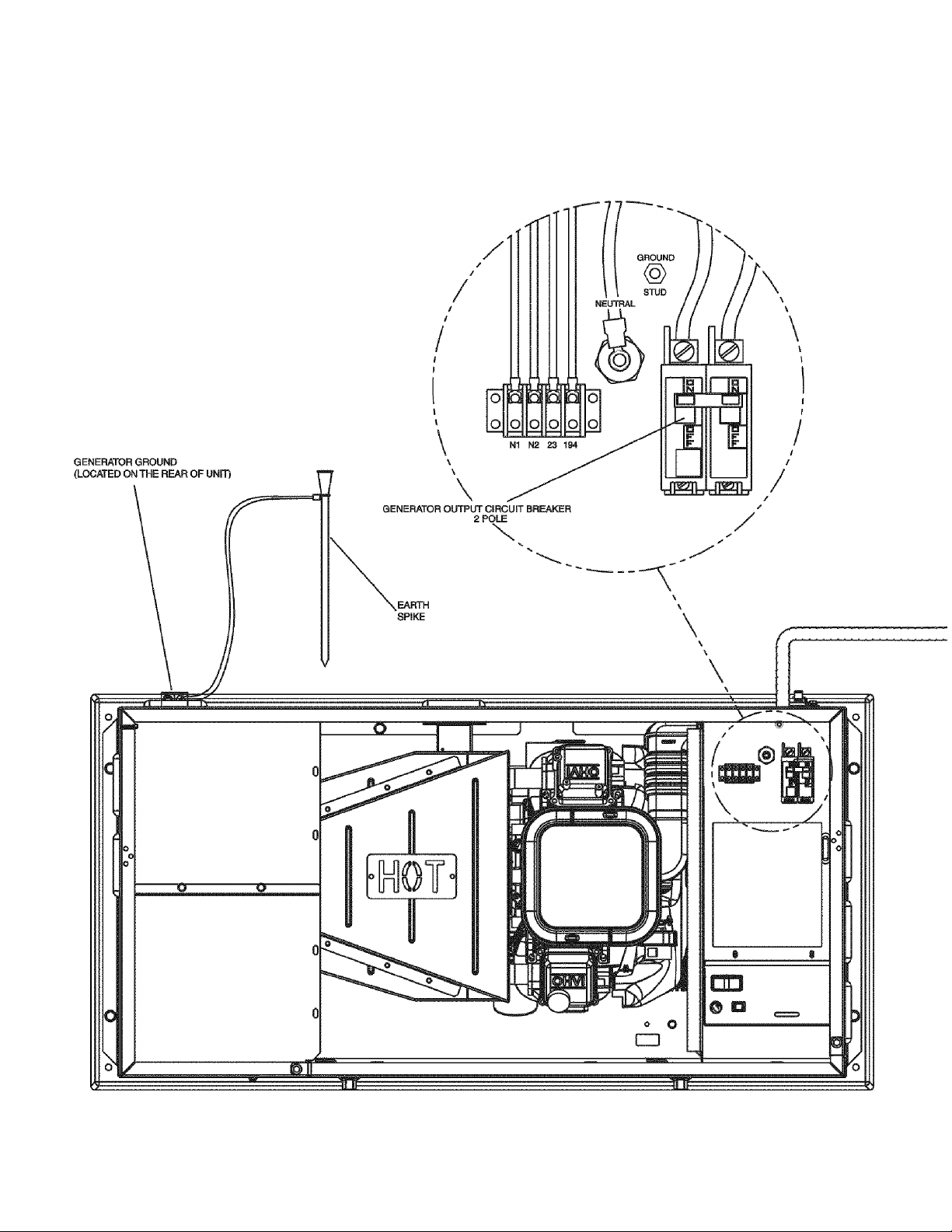
Attach one end of the grounding strap (No. 12 AWG stranded
copper wire) to grounding rod and the other end to the grounding
lug (located at rear corner of unit). Make sure grounding rod and
strap are not exposed above ground level. (NEC code applies to
grounding method.)
NOTE: Generator mode switch should be placed in the “off”
position. Generator main line circuit breaker should be
switched to “off” or open position.
9a. Make the connection between the rigid fuel piping and the
generator using the supplied threaded flexible fuel line. The flex
hose should be straight.
pipe elbows.
connections. Check connections for leaks by opening manual
fuel shut-off valve and swab or spray connections with soapy
water. If a leak exists the area will bubble with the presence of
the soapy water.
9b. It a leak is located, shut off fuel, and disconnect flexible piping.
Dry the threaded ends and reapply an adequate amount of pipe
sealant. Reconnect flexible fuel line, open fuel supply and
recheck for leaks. If leak still exists, repeat step 9b.
Do not bend the hose in place of using
Use a pipe sealant suitable for gaseous fuel
PLEASE NOTE:
inlet on the generator must be 5 - 7” W.C. (0.18 to
0.25 psi). LP gas pressure to the fuel inlet on the
generator must be 10 -12" W.C. (0.36 to 0.43 psi)
A primary regulator must be used if unit is
connected to an LPfuel tank (Primary regulator is
not supplied).
Natural gas pressure to the fuel
Qonverting to LP gas
From the factory, units are set-up for natural gas
operation. To convert for operation on LP gas refer to
“Reconfiguringthefuelsystem”\n
the
Owner’s Manual.
Page 7

10a. Determine where the flexible conduit will pass through the house from inside to outside.
10b. Using a hole saw, drill a 1-3/4 inch diameter hole in the house’s wall to allow the conduit
11a. From the inside of the house, feed the end of the 30-foot conduit (which is pre-wired from
lib. Remove the threaded lock nut from the conduit coupling.
11c. Lift cover. Remove internal oover plate screw and internal cover.
The outer diameter of the threaded end is 15/16".
STEP 3
When you are certain you have clearance on each side and within the wall, drill a small pilot
hole through the wall to mark the location.
to fit through.
transfer switch) through the wall to outside.
Remove the knock out in the lower right corner of the external
connection box. From the rear of the connection box, feed wires
& 4 pin plug into box. Slip the lock nut over wires and plug and
tighten securely onto conduit coupling. Using appropriate
fasteners, mount external connection box over pre-drilled hole to
fully conceal the hole. Seal around the hole and conduit with
silicone caulk from both the inside and outside of the home.
Also, caulk around the sides and top of the box to seal the edges to the siding or wall.
Connect wires to lugs; Black to black, white to white, and red to red. Torque nuts to 20
in/lbs. Snap together the 4-pin plug connector. Loosen nut from grounding lug and attach
ground wire (green) from conduit. Reinstall nut and tighten to 45 in/lbs. Reinstall internal
cover plate and screw. Close cover and install lock. This wiring is complete.
CONNECTION TO EXTERNAL CONNECTION BOX
—
Ground
Screw
- M
MiSi
Knockout
A
DANGER
licensed electrician or individual with complete
knowledge of electricity perform the procedures
in sections 12.13a. and 13b.
A
DANGER
wiring of fhe main electrical distribution panel.
The wires connected to
the service main circuit
breaker remain live or
‘ hot". Avoid contact with
these wires and the
service main circuit breaker connection lugs.
NOTE: Balance must be maintained when moving
circuit locations from main electrical
distribution panel to emergency load center.
Circuit breaker positions alternate buss bars
vertically. Circuits sharing a neutral wire should
either be moved together to adjacent positions in
emergency load center or not moved. If you are
unsure of proper procedure or if your installation
differs from that described in this guide, consult
a licensed professional at this time.
Although you may choose to perforrh
electrical connections yourse^^^
CARRIER recommends that a
12. Locate automatic transfer switch with built-in emergency load
Switch service main circuit breaker
to off" or open posifion prior to
removal of cover or removal of any
I I I I I I
13a. Remove the main electrical distribution panel cover. Remove
The external connection box must be locked to
ensure safety and to discourage tampering.
STEP 4
main distribution panel. The automatic
transfer switch with built-in load center can
be located to the left or right of main
distribution panel. Hold transfer switch
against the mounting surface. Level the
transfer switch and mark the mounting
holes. Drill the appropriate size pilot holes.
Mount automatic transfer switch with builtin load center to mounting surface with
appropriate fasteners.
STEPS
appropriate size knockout from the bottom or side of the main panel.
(A 2-foot flexible conduit is pre-wired from the transfer switch with
built-in load center.) Remove threaded lock nut from conduit
coupling. Feed all wires through knockout into main panel. Slip lock
nut over wires and tighten securely on conduit coupling. Remove the
black (hot) wire from a circuit breaker that protects a circuit you
want to have powered in the event of a power failure. -
MOUNTING THE AUTOMATIC TRANSFER SWITCH
CONNECTION OF EMERGENCY CIRCUITS
continued on
page 8
center within one foot of
Page 8

■
continued from page 7
Wire nut the black wire to the matching
circuit lead wire from the emergency
circuit breaker from load center in the
transfer switch. (All circuit wires are color
coded and labeled for easy
identification).
UL approved wire
locknuts are included in installation kit.
Trace the black (hot) wire you have just
connected back to the same Romex cable (circuit) to find its mating
white (neutral) wire. Wire nut this wire to the matching circuit number
on the white (neutral) wire coming from the emergency load center.
Repeat this process with remaining circuits to be powered by the
generator.
NOTE: Both grounded and ungrounded conductors for each circuit
must be reconnected to the emergency load center wiring using
the supplied wire locknuts.
The chart below shows the circuits provided in the load center.
7kW lOkW 13kW 16kWS
Circuits 50A:240V
:i:i ■■ ■■ '.4eA:240V
^ TQA 240V 1 1 1
::: : - 20A24GV
: : : : : 20A I20V 1 3 3 5 5
15A1E0V.
. . .
_ _
_
5 3 5 5 5
1
1 1 1
_
mimim
1 1
_ _
1 1
NOTE: Circuits to be moved must be protected by same size
breaker. For example, a 15 Amp circuit in main panel must be a 15
Amp circuit in transfer switch.
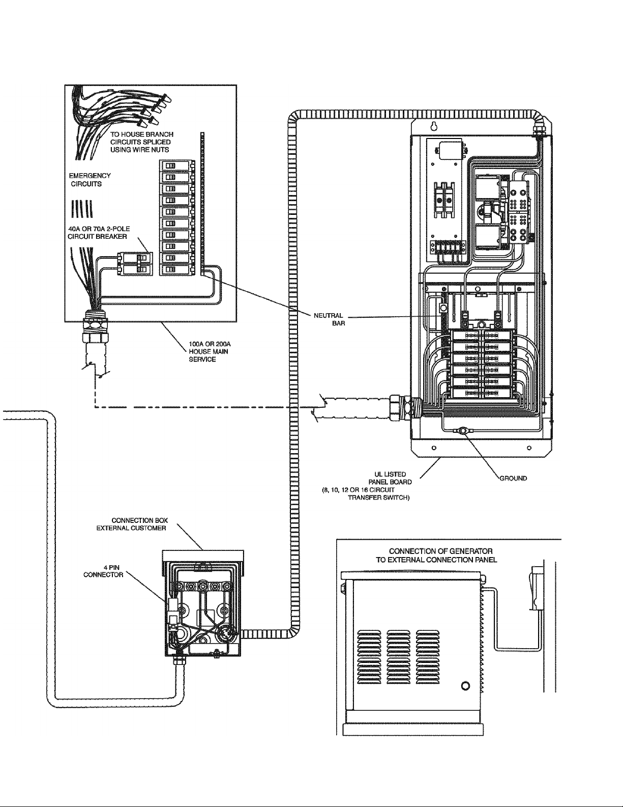
13b. Install the 40 Amp or 70 Amp double pole
circuit breaker that you have purchased
(See detail on page 6) into main electrical
distribution panel. This circuit breaker
must be compatible with your main
electrical distribution panel.
necessary to reposition remaining circuit
breakers or remove circuit breakers that
have been disconnected to accommodate the insertion of the 40 Amp
or 70 Amp double pole circuit breaker. Connect white wire to the main
distribution panel neutral bar. Connect green wire to main electrical
panel ground bar. Connect the black and red wires to the 40 Amp or
70 Amp double pole circuit breaker.
It may be
STEP CONNECT STARTING BAHERY
14. Recommended battery is automotive type
Group 26 12V negative ground with
minimum 350 CCA at 0° F (7 kW) or a
minimum 525 CCA at 0°F (10 kW, 13 kW
and 16 kW). The hold down clamp is
included. Connect positive (+)
cable to positive (+) battery post.
Connect negative (-)
cable to negative (-) battery post.
A
WARNING Set tbe generator’s AUTO/OFF/MANUALswitch to “OFF.”
(black)
Turn off utility power supply to the transfer switch. If the AUTO /
OFF / MANUAL switch is not set to its “OFF” position, the generator
can crank and start as soon as the battery cables are connected.
(red)
ground
Battery area
dimensions 8" Lx 8" W
A
WARNING If tbe utility power supply is not turned off, sparking can
occur at the battery posts and cause an explosion.
NOTE: Dielectric grease should be used on battery posts to aid in
tbe prevention of corrosion.
NOTE: In areas where temperatures regularly fall below 10° F
(-12° C) it is recommended that a pad type battery heater be
installed to aid in cold climate starting.
READY THE SYSTEM FOR RETURN
STEP 7
15. Switch service main circuit breaker to “on” or closed position. Switch
the circuit breakers in the emergency distribution panel to the “on” or
closed position. Switch the generator main line circuit breaker to the
"on” or closed position. Verify that the 40 Amp or 70 Amp double pole
circuit breaker that was inserted in the main electrical distribution
panel is switched to the ”on” or closed position. Place generator mode
switch in the “AUTO” position. Verify that fuel valve on rigid gas
piping is open.
Installation & Owner’s Manual prior to testing the system.
STEP
16. Switch service main circuit breaker to “off" or open position. This
simulates the loss of utility power. The generator should crank and
start within 20 seconds. Load transfer should occur within 10
seconds of generator start. To return system to automatic mode,
switch service main breaker to “on” or closed position. This simulates
the return of power from the utility. The generator will run for a short
cool down period of several minutes while the entire system stands
ready for the next power outage.
NOTE: When utility voltage source is lost hy the generator, the
system set light will flash rapidly.
STEP
17. A switch on the control
panel allows you to select
the day and time for the
system to exercise. To select
a time and day of the week
you must perform the
following sequence at that time. Verify that the Auto/Off/Manual
switch is set to “AUTOI'
Hold down the “Set Exercise lime” switch until the generator starts
(approximately 10 seconds) and release. The generator will start and
run for approximately twelve minutes and then shut down on its own.
The generator is now set to exercise on that day and at that time every
week. If the battery is disconnected for any reason the exercise time
must be reset.
flash in the Auto or Manual mode.
AUTOMATIC OPERATION
Perform steps in Sections 2.1 through 2.5 of the
TEST SYSTEM
SET EXERCISER
Exerciser Switch
NOTE: Until the exerciser is set, all the red LED's will
Your CARRIER Home Standby
generator is now ready!
Turn to the Experts
Part # 0G0598 REV, * CATALOG NO.ASPB07-1SI PRINTED IN THE USA 5.06
 Loading...