

Page 1
Marine/Industrial
Single Package
Cooling Unit
Models
90MA/MF/MU, Design Series Two
Beginning Serial Number C00400
62--10458--00
INSTALLATION
OPERATION & SERVICE
Page 2
OPERATION AND SERVICE MANUAL
MARINE/INDUSTRIAL SINGLE PACKAGE
COOLING UNIT
MODELS
90MA/MF/MU, Design Series Two
Beginning Serial Number C00400
Carrier Refrigeration Operations, A member of the United Technologies Corporation family. Stock symbol UTX.
Carrier Transicold, Carrier Corporation, P.O. Box 4805, Syracuse, N.Y. 13221 U. S. A.
Carrier Corporation 2000 D Printed in U. S. A. 0700
Page 3

SAFETY SUMMARY
GENERAL SAFETY NOTICES
The following general safety notices supplement the specific warnings and cautions appearing elsewhere in this
manual. They are recommended precautions that must be understood and applied during operation and maintenance
of the equipment covered herein. The generalsafety notices are presented in the following three sections labeled: First
Aid, Operating Precautions and Maintenance Precautions. A listing of the specific warnings and cautions appearing
elsewhere in the manual follows the general safety notices.
FIRST AID
An injury, no matter how slight, should never go unattended. Always obtain first aid or medical attentionimmediately.
OPERATING PRECAUTIONS
Always wear safety glasses.
Keep hands, clothing and tools clear of the evaporator and condenser fans.
No work should be performed on the unit until all circuit breakers, start-stop switches are turned off, and power supply
is disconnected.
Always work in pairs. Never work on the equipment alone.
In case of severe vibration or unusual noise, stop the unit and investigate.
MAINTENANCE PRECAUTIONS
Beware of unannounced starting of the evaporator fan. Do not open the evaporator access panels before turning power
off, disconnecting and securing the power source.
Be sure power is turned off before working on motors, controls, solenoid valves and electrical control switches. Tag
circuit breaker and power supply to prevent accidental energizing of circuit.
Do not bypass any electrical safety devices, e.g. bridging an overload, or using any sort of jumper wires. Problems
with the system should be diagnosed, and any necessary repairs performed, by qualified service personnel.
In case of electrical fire, open circuit switch and extinguish with CO
(never use water).
2
SPECIFIC WARNING AND CAUTION STATEMENTS
To help identify the label hazards on the unit and explain the level of awareness each one carries, an explanation is
given with the appropriate consequences:
WARNING -- means to warn against hazards or unsafe conditions which could result in severe personal injury or
death.
CAUTION -- means to warn against potential hazard or unsafe practice which could result in product or property
damage.
The statements listed below are applicable to the unit and appear elsewhere in this manual. These recommended
precautions must be understood and applied during operation and maintenance of the equipment covered herein.
WARNING
Never reach into unit while fan is running. Lock open and tag unit disconnect before working on fan.
Remove fuses and take them with you after noting this on tag.
WARNING
Follow all Safety codes. Wear safety glasses and rubber gloves when using inhibited hydrochloricacid
solution.
WARNING
Lock open and tag unit disconnect before working on fan motor. Remove fuses and take them with you
after noting this on tag.
CAUTION
Compressor crankcase heater must be energized for 24 hours prior to start up to prevent compressor
bearing damage.
Safety-1
62--10458--00
Page 4

CAUTION
Sharp edges of coil fins are exposed. To prevent injury, cover top of evaporator with cardboard or a few
layers of heavy tape.
CAUTION
To avoid coil damage, cover evaporator face with plywood or other rigid sheet material. If any coil fins
are mashed or bent, straighten with a coil fin comb of the proper tooth spacing (refer to “coil fins/inch”
in Table 1 through Table 2). Check for refrigerant leaks.
CAUTION
Before attempting to remove fan motors or motor mounts, place a piece of plywood over evaporator
coils to prevent coil damage.
62--10458-- 00
Safety-2
Page 5

TABLE OF CONTENTS
PARAGRAPH NUMBER Page
GENERAL SAFETY NOTICES Safety-1.....................................................
FIRST AID Safety-1......................................................................
OPERATING PRECAUTIONS Safety-1......................................................
MAINTENANCE PRECAUTIONS Safety-1..................................................
SPECIFIC WARNING AND CAUTION STATEMENTS Safety-1.................................
1. INTRODUCTION 1..............................................................
2. MODEL CHART 1...............................................................
3. INSTALLATION 1...............................................................
3.1 Inspect Unit 1................................................................
3.2 Protect Unit from Damage 1.....................................................
3.3 Provide Unit Support 1.........................................................
3.4 Install Accessory Heating Coil (if applicable) 1......................................
3.5 Rig and Place Unit 1...........................................................
3.6 Install Accessory Plenum (If Supplied) 1...........................................
3.7 Install Ventilation--Air Ductwork (If required) 1.....................................
3.8 Install Return Air Ductwork (If required) 1.........................................
3.9 Check Return--Air Filters 5......................................................
3.10 Align Fan Shaft and Wheel 5....................................................
3.11 Check Compressor Spring Mounts (008 & 012 size only) 6............................
3.12 Make Condenser C onnections 6..................................................
3.13 Install Condensate Drain Line 7..................................................
3.14 Make Electrical Connections 7...................................................
4. OPERATION 8..................................................................
4.1 To Start Unit 8...............................................................
4.2 T o Shut Down Unit 8..........................................................
4.3 Sequence Of Operation 8.......................................................
5. SERVICE 9.....................................................................
5.1 Return--Air Grille Removal 9....................................................
5.2 Access Panel Removal 9........................................................
5.3 Evaporator Fan Adjustment 9....................................................
5.4 Return--Air Filter 10............................................................
5.5 Condensate Drain 10............................................................
5.6 Evaporator Coil 10.............................................................
5.7 Water Regulating Valve 10.......................................................
5.8 Condenser 10.................................................................
5.9 Refrigerant Charging 11.........................................................
5.10 Evaporator Fan Motor Removal 12................................................
5.11 Pressure Relief Device 12........................................................
5.12 Crankcase Heater 12............................................................
5.13 Cycle--LocTM -- Protection Device 12..............................................
5.14 Discharge and Suction Pressure Switches 12.........................................
5.15 Oil Charge 12.................................................................
i 62--10458-- 00
Page 6

LIST OF ILLUSTRATIONS
FIGURE NUMBER Page
Figure 1 Base Unit Interior Details (Typical) 1................................................
Figure 2 Unit Dimensions 5...............................................................
Figure 3 Horizontal Wheel Centering 5......................................................
Figure 4 Concentric Wheel Alignment 5.....................................................
Figure 5 Connection Locations 6...........................................................
Figure 6 Typical Condenser Water Piping 6...................................................
Figure 7 Condensate Drain Trap 7..........................................................
Figure 8 Fan Pulley Adjustment 9..........................................................
Figure 9 Gravity Flow Method 10...........................................................
Figure 10 Forced Circulation Method 11......................................................
Figure 11 Charging Charts 11...............................................................
Figure 12 Mounting Base 13...............................................................
Figure 13 Wiring Schematic -- 90MA/MF/MU004/006 14........................................
Figure 14 C omponent Arrangement -- 90MA/MF/MU004/006 15..................................
Figure 15 Wiring Schematic -- 90MA/MF/MU008/012 16........................................
Figure 16 C omponent Arrangement -- 90MA/MF/MU008/012 17..................................
LIST OF TABLES
TABLE NUMBER Page
Table 1 90MA/MF/MU Physical Data -- Refrigerant 22 2.........................................
Table 2 90MA/MF/MU Physical Data -- Refrigerant 407C 3.......................................
Table 3 90MA/MF Physical Data -- Refrigerant 134a 4...........................................
Table 4 R ecommended Line Sizes, Remote Condenser 7.........................................
62--10458-- 00
ii
Page 7
1. INTRODUCTION
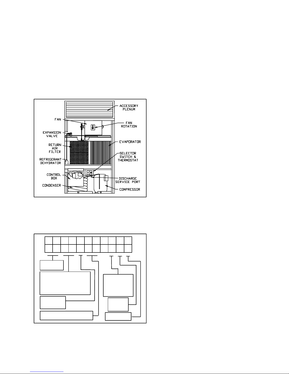
The 90M series single--package cooling units (See
Figure 1) are designed to provide air conditioning
aboard marine vessels and in industrial applications.
The 90MA units are fitted with sea water cooled
condensers while the 90MF units are fitted with fresh
water cooled condensers. Both units are factory
charged, wired and piped. The 90MU units are similar
except they are configured for use with a remote
mounted condenser.
An accessory discharge plenum may be installed to
provide free--blow into the conditioned space. Also, an
accessory electric, hot water or steam coil heater may be
installed to provide comfort heating.
3.1 Inspect Unit
Check unit against shipping order. Inspect carefully for
concealed shipping damage. If shipment is damaged or
incomplete,file claim w ith transportation company and
advise Carrier Transicold immediately.
3.2 Protect Unit from Damage
To maintain warranty, protect unit against adverse
weather, theft, or vandalism on j ob site.
3.3 Provide Unit Support
Refer to Figure 2 and Table 1 through Table 2 for unit
size and weight. If desired, construct a frame of I--beams
or angle iron that adequately supports unit. See
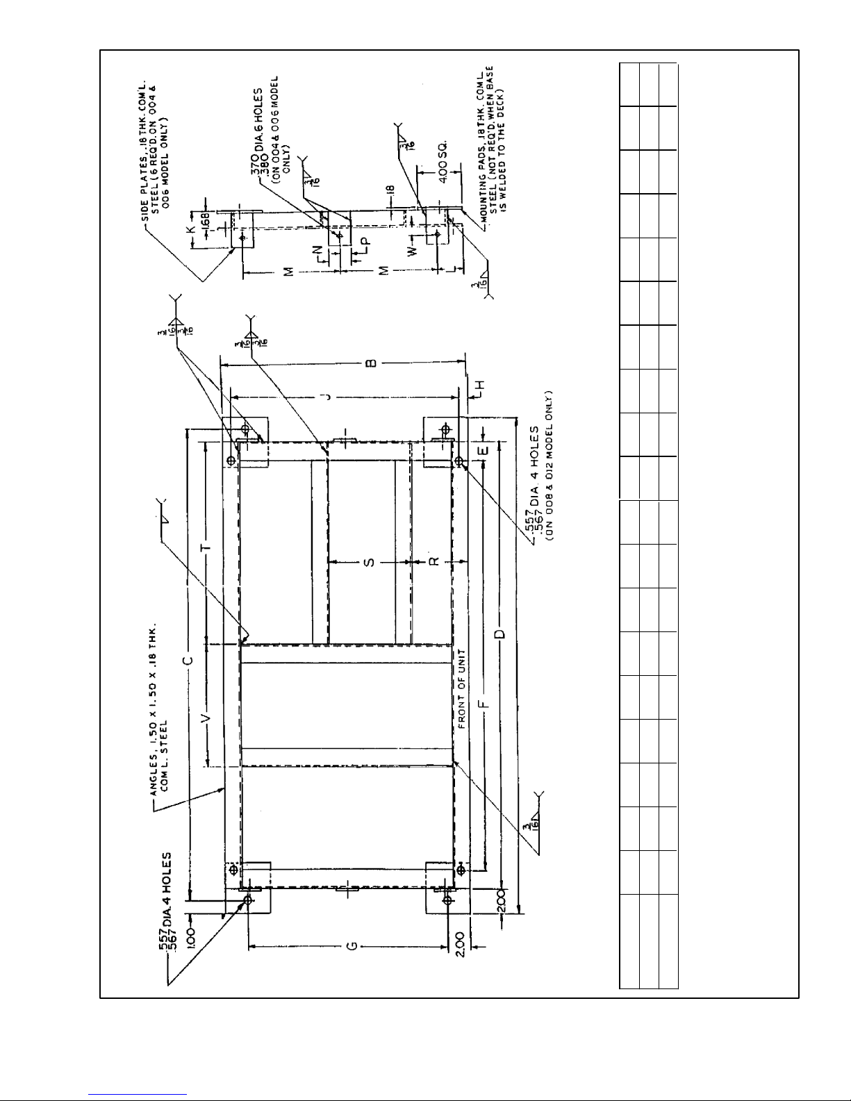
Figure 12.
3.4 Install Accessory Heating Coil (if applicable)
Electric heaters are installed at the top of the unit. Water
or steam coil must be installed through the back of the
unit as described in the Installation Instructions shipped
with the accessory coil.
3.5 Rig and Place Unit
NOTE
Install accessories before placing unit.
(90MA/MF
ONLY)
Figure 1 Base Unit Interior Details (Typical)
2. MODEL CHART
This manual covers 90M design series two units as
shown in the following model chart.
1 234 56 7891011
0MA
9
PRODUCT
CODE
MODEL
MA - 90/10 Copper Nickel
Condenser
MF - Copper Condenser
MU - Condenserless
2-R-22
3 - R-134a
4 - R-407C
NOMINAL COOLING
CAPACITY (R--22)
3 1 2 --- 6 2
VOLTAGE
5 - 208/230-3-60
6 - 460-3-60
9 - 400-3-50
DESIGN
SERIES
PACKAGING
1
3. INSTALLATION
To install the unit, do the following:
a. Provide space around unit for service, filter access,
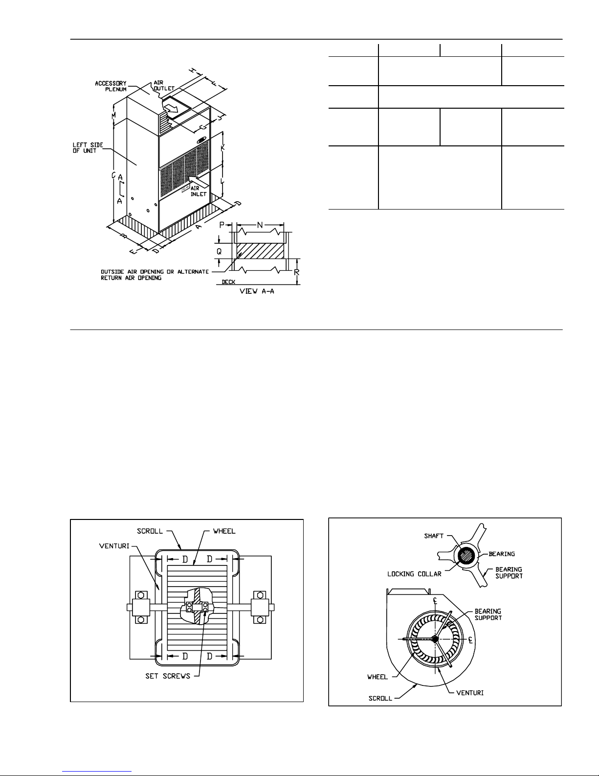
and overhead clearance as indicated in Figure 2.
b. Move and store unit in upright position.
c. Useslings with spacer under base skid to prevent pan-
el damage when using hoist.
d. Units as shipped are adequately dampened against
vibration. If additional dampening is desired, place
sponge rubber or rubber mat, between deck and base
of unit or install vibration isolators.
e. Unit should be level. Unit leveling tolerance is 1/8
inch per linear foot in any direction.
3.6 Install Accessory Plenum (If Supplied)
Use plenum as template to mark hole locations in top
panel. Drill 5/32--in. (0.4 cm) holes in top panel at
marked locations and attach plenum with screws
supplied.
3.7 Install Ventilation--Air Ductwork
(If required)
Connect ventilation ducts to flanges on outside--air
supply opening (See Figure 2) using a flexible
connection. Attach ductwork to ship structure and
insulate with fiberglass and vapor barrier to reduce
sound transmission and prevent vapor condensation.
Weatherproof external ductwork, joints, and openings
in accordance with applicable codes. Ducts passing
through an unconditioned space must be insulated and
covered with a vapor barrier.
3.8 Install Return Air Ductwork (If required)
The unit back panel is to be field cut for alternate
return--air (or outdoor--air inlet) opening as indicated in
Figure 2. To install ductwork:
a. Cut out the alternate return--air opening as required.
1
62--10458-- 00
Page 8
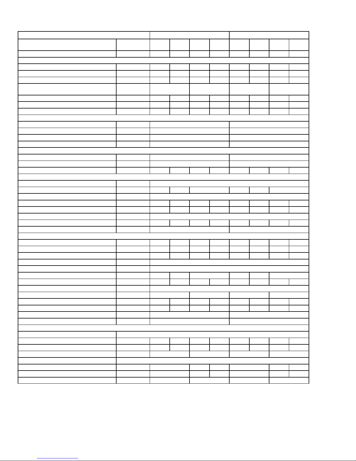
Table 1 90MA/MF/MU Physical Data -- Refrigerant 22
R--22 -- English Units R--22 -- Metric Units
BASE UNIT 90MA/MF/MU UNITS
NOMINAL CAPACITY Tons (kW) 3 5 7.5 10 10.5 17.6 26.4 35.1
OPERATING WEIGHT
Base Unit -- 90MA/MF Pounds (kg) 390 427 895 950 177 194 406 431
Base Unit -- 90MU Pounds (kg) 330 360 835 890 150 163 379 404
Discharge Plenum Pounds (kg) 25 25 50 50 11.3 11.3 22.7 22.7
COMPRESSOR TYPE Welded Hermetic
Quantity of Cylinders -- -- 4 6 -- -- 4 6
Quantity of Unloading Cylinders -- -- 0 2 -- -- 0 2
Quantity of Capacity Steps -- -- 1 2 -- -- 1 2
DISCHARGE PRESSURE SWITCH
Opens -- 90MA/MF psig (kPa) 39510 272569
Closes -- 90MA/MF psig (kPa) 29520 2034138
Opens -- 90MU psig (kPa) 4267 293748
Closes -- 90MU psig (kPa) 32020 2206138
SUCTION PRESSURE SWITCH
Opens psig (kPa) 274 18628
Closes psig (kPa) 677 46248
OPERATING CHARGE -- 90MA/MF pounds (kg) 3.1 5.3 11. 2 10 1.4 2.4 5.1 4.5
CONDENSER -- 90MA/MF
Number & Type 1....Tube In Tube
Water Volume gallon (liter) 0.39 0.86 2.42 1.48 3.3 9.2
EVAPORATOR AIR FAN Adjustable, Belt Driven Centrifugal: 1750 RPM Motor @ 60 Hz
Nominal Flow cfm (m3/h) 1200 2000 3000 4000 1698 2830 4245 5660
Standard Speed Range RPM 525-750 647-915 495-700 600-850 427-652 593-762 412-583 500-708
Maximum Allowable RPM 1050
Belt Quantity / Pulley Pitch Diameter inches (cm) 1/8.0 1/6.4 1/8.5 1/7.0 1 / 20.3 1 / 16.3 1 / 21.6 1 / 17.8
Motor Pulley Pitch Diameter Range inches (cm) 2.4to3.4 6.1to8.6
Motor Nominal Rating(@60 Hz)...Frame Size
Standard horse power 1/3...56 3/4...56 1...56 2...56 .25 / 56 .56 / 56 .75 / 56 1.5 / 56
Alternate(SeeNote1) horse power 3/4...56 1...56 2...56 3...56 .56 / 56 .75 / 56 1.5 / 56 2.2 / 56
Alternate(SeeNote1) horse power -- -- -- -- 3...56 -- -- -- -- -- -- 2.2 / 56 -- -EVAPORATOR COIL 3/8 (.95 cm) OD, Copper Tubes, Aluminum Fins
Tube Type Prime
Quantity of Rows...fin Spacing fins/inch(cm) 2...14.4 3...14.4 3...12.5 2...5.7 3...5.7 3...4.9
Face Area sq ft (sq m) 5 5 7.3 8.5 0.46 0.46 0.68 0.79
RETURN AIR FILTERS Factory Supplied, Cleanable
Quantity...Size inches (cm) 2...16 x 25 x 1 4...16 x 20 x 1 2...40.6x63.5x2.5 4...40.6x50.8x2.5
CONDENSER CONNECTIONS
Water Inlet (bottom) & Outlet (top) inches FPT 1/2 3/4 1 1 1/2 3/4 1 1
Maximum Working Pressure (refrigerant side) psig (kPa) 400 2758
CONDENSATE DRAIN CONNECTIONS inches FPT 3/4 3/4
ACCESSORY HEATING COILS
HOT WATER
Quantity of Rows...fin spacing fins/inch(cm) 1...15 1...15 2...14 2...14 1...5.9 1...5.9 2...5.5 2...5.5
Face Area sq ft (m) 5 5 6 6 0.46 0.46 0.56 0.56
Water Inlet (top) & Outlet Connection (bottom) inches (cm) 7/8 ODF 1--1/4 MPT 7/8 ODF 1-- 1/4 MPT
STEAM
Quantity of Rows...fin spacing fins/inch(cm) SeeNote2 1...14 1...14 SeeNote2 1...5.5 1...5.5
Face Area sq ft (m) SeeNote2 6.9 6.9 SeeNote2 0.64 0.64
Water Inlet (top) & Outlet Connection (bottom) inches (cm) SeeNote2 1--1/4 MPT SeeNote2 1--1/4 MPT
English (Metric)
LEGEND
FPT = Female Pipe Thread MPT = Male Pipe Thread ODF = Outside Diameter Female
204 206 208 212 204 206 208 212
Scroll
Semi--Hermetic
Reciprocating
Welded Hermetic
Scroll
Semi--Hermetic
Reciprocating
NOTES:
1. Motors and drives other than those furnished with unit must be purchased separately. Contact your Carrier Transicold representative.
2. Accessory heating coil in 004 and 006 units is combination hot water/steam. See hot water data.
62--10458-- 00
2
Page 9
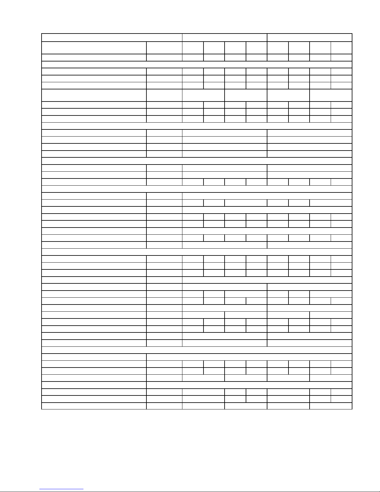
Table 2 90MA/MF/MU Physical Data -- Refrigerant 407C
R--407C -- English Units R--407C -- Metric Units
BASE UNIT 90MA/MF/MU UNITS
NOMINAL CAPACITY Tons (kW) 3 5 7.5 10 10.5 17.6 26.4 35.1
OPERATING WEIGHT
Base Unit -- 90MA/MF Pounds (kg) 390 427 895 950 177 194 406 431
Base Unit -- 90MU Pounds (kg) 330 360 835 890 150 163 379 404
Discharge Plenum Pounds (kg) 25 25 50 50 11.3 11.3 22.7 22.7
COMPRESSOR TYPE Welded Hermetic
Quantity of Cylinders -- -- 4 6 -- -- 4 6
Quantity of Unloading Cylinders -- -- 0 2 -- -- 0 2
Quantity of Capacity Steps -- -- 1 2 -- -- 1 2
DISCHARGE PRESSURE SWITCH
Opens -- 90MA/MF psig (kPa) 39510 272569
Closes -- 90MA/MF psig (kPa) 29520 2034138
Opens -- 90MU psig (kPa) 4267 293748
Closes -- 90MU psig (kPa) 32020 2206138
SUCTION PRESSURE SWITCH
Opens psig (kPa) 274 18628
Closes psig (kPa) 677 46248
OPERATING CHARGE -- 90MA/MF pounds (kg) 3.1 5.3 11. 2 10.0 1.4 2.4 5.1 4.5
CONDENSER -- 90MA/MF
Number & Type 1....Tube In Tube
Water Volume gallon (liter) 0.39 0.86 2.42 1.48 3.3 9.2
EVAPORATOR AIR FAN Adjustable, Belt Driven Centrifugal: 1750 RPM Motor @ 60 Hz
Nominal Flow cfm (m3/h) 1200 2000 3000 4000 1698 2830 4245 5660
Standard Speed Range RPM 525-750 647-915 495-700 600-850 427-652 593-762 412-583 500-708
Maximum Allowable RPM 1050
Belt Quantity / Pulley Pitch Diameter inches (cm) 1/8.0 1/6.4 1/8.5 1/7.0 1 / 20.3 1 / 16.3 1 / 21.6 1 / 17.8
Motor Pulley Pitch Diameter Range inches (cm) 2.4to3.4 6.1to8.6
Motor Nominal Rating(@60 Hz)...Frame Size
Standard horse power 1/3...56 3/4...56 1...56 2...56 .25 / 56 .56 / 56 .75 / 56 1.5 / 56
Alternate(SeeNote1) horse power 3/4...56 1...56 2...56 3...56 .56 / 56 .75 / 56 1.5 / 56 2.2 / 56
Alternate(SeeNote1) horse power -- -- -- -- 3...56 -- -- -- -- -- -- 2.2 / 56 -- -EVAPORATOR COIL 3/8 OD, Copper Tubes, Aluminum Fins
Tube Type Prime Prime
Quantity of Rows...fin Spacing fins/inch(cm) 2...14.4 3...14.4 3...12.5 2...5.7 3...5.7 3...4.9
Face Area sq ft (sq m) 5 5 7.3 8.5 0.46 0.46 0.68 0.79
RETURN AIR FILTERS Factory Supplied, Cleanable Factory Supplied, Cleanable
Quantity...Size inches (cm) 2...16 x 25 x 1 4...16 x 20 x 1 2...40.6x63.5x2.5 4...40.6x50.8x2.5
CONDENSER CONNECTIONS
Water Inlet (bottom) & Outlet (top) inches FPT 1/2 3/4 1 1 1/2 3/4 1 1
Maximum Working Pressure (refrigerant side) psig (kPa) 400 2758
CONDENSATE DRAIN CONNECTIONS inches FPT 3/4 3/4
ACCESSORY HEATING COILS
HOT WATER
Quantity of Rows...fin spacing fins/inch(cm) 1...15 1...15 2...14 2...14 1...5.9 1...5.9 2...5.5 2...5.5
Face Area sq ft (m) 5 5 6 6 0.46 0.46 0.56 0.56
Water Inlet (top) & Outlet Connection (bottom) inches (cm) 7/8 ODF 1--1/4 MPT 7/8 ODF 1-- 1/4 MPT
STEAM
Quantity of Rows...fin spacing fins/inch(cm) SeeNote2 1...14 1...14 SeeNote2 1...5.5 1...5.5
Face Area sq ft (m) SeeNote2 6.9 6.9 SeeNote2 0.64 0.64
Water Inlet (top) & Outlet Connection (bottom) inches (cm) SeeNote2 1--1/4 MPT SeeNote2 1--1/4 MPT
English (Metric)
LEGEND
FPT = Female Pipe Thread MPT = Male Pipe Thread ODF = Outside Diameter Female
404 406 408 412 404 406 408 412
Scroll
Semi--Hermetic
Reciprocating
Welded Hermetic
Scroll
Semi--Hermetic
Reciprocating
NOTES:
1. Motors and drives other than those furnished with unit must be purchased separately. Contact your Carrier Transicold representative.
2. Accessory heating coil in 004 and 006 units is combination hot water/steam. See hot water data.
3
62--10458-- 00
Page 10
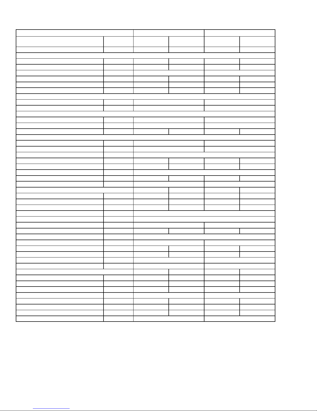
Table 3 90MA/MF Physical Data -- Refrigerant 134a
R--134a -- English Units R--134a -- Metric Units
BASE UNIT 90MA/MF UNITS
NOMINAL CAPACITY Tons (kW) 5.5 8 19.3 28.1
OPERATING WEIGHT
Base Unit Pounds (kg) 895 950 406 431
Discharge Plenum Pounds (kg) 50 50 22.7 22.7
COMPRESSOR TYPE -- Reciprocating Semi--Hermetic Semi--Hermetic
Quantity of Cylinders 4 6 4 6
Quantity of Unloading Cylinders 0 2 0 2
Quantity of Capacity Steps 1 2 1 2
DISCHARGE PRESSURE SWITCH
Opens psig (kPa) 33510 231069
Closes psig (kPa) 23520 1620138
SUCTION PRESSURE SWITCH
Opens psig (kPa) 73 4821
Closes psig (kPa) 225 15235
OPERATING CHARGE pounds (kg) 11.2 10 5.1 4.5
CONDENSER
Number & Type 1....Tube In Tube 1....Tube In Tube
Water Volume gallon (liter) 2.42 9.2
EVAPORATOR AIR FAN Adjustable, Belt Driven Centrifugal: 1750 RPM Motor @ 60 Hz
Nominal Flow cfm (m3/h) 3000 4000 4245 5660
Standard Speed Range RPM 495--700 600--850 412--583 500--708
Maximum Allowable RPM 1050
Belt Quantity / Pulley Pitch Diameter inches (cm) 1/8.5 1/7.0 1 / 21.6 1 / 17.8
Motor Pulley Pitch Diameter Range inches (cm) 2.4to3.4 6.1to8.6
Motor Nominal Rating(@60 Hz)...Frame Size
Standard horse power 1...56 2...56 .75 / 56 1.5 / 56
Alternate(SeeNote1) horse power 2...56 3...56 1.5 / 56 2.2 / 56
Alternate(SeeNote1) horse power 3...56 -- -- 2.2 / 56 -- -EVAPORATOR COIL 3/8 OD(0.95) cm, Copper Tubes, Aluminum Fins
Tube Type Prime
Quantity of Rows...fin Spacing fins/inch(cm) 3...12.5 3...14.9
Face Area sq ft (sq m) 7.3 8.5 0.68 0.79
RETURN AIR FILTERS Factory Supplied, Cleanable
Quantity...Size inches (cm) 4...16 x 20 x 1 4...40.6 x 50.8 x 2.5
CONDENSER CONNECTIONS
Water Inlet (bottom) & Outlet (top) inches FPT 1 1 1 1
Maximum Working Pressure (refrigerant side) psig (kPa) 400 2758
CONDENSATE DRAIN CONNECTIONS inches FPT 3/4 3/4
ACCESSORY HEATING COILS
HOT WATER
Quantity of Rows...fin spacing fins/inch(cm) 2...14 2...14 2...5.5 2...5.5
Face Area sq ft (m) 6 6 0.56 0.56
Water Inlet (top) & Outlet Connection (bottom) inches (cm) 1-- 1/4 MPT 1-- 1/4 MPT
STEAM
Quantity of Rows...fin spacing fins/inch(cm) 1...14 1...14 1...5.5 1...5.5
Face Area sq ft (m) 6.9 6.9 0.64 0.64
Water Inlet (top) & Outlet Connection (bottom) inches (cm) 1-- 1/4 MPT 1-- 1/4 MPT
English (Metric)
308 312 308 312
LEGEND
FPT = Female Pipe Thread MPT = Male Pipe Thread ODF = Outside Diameter Female
NOTES:
1. Motors and drives other than those furnished with unit must be purchased separately. Contact your Carrier Transicold representative.
62--10458-- 00
4
Page 11
UNIT
A
B
C
D SEE NOTE 2
E 24(610)
F
G
H
J
K
L
M
N
P
Q
R
NOTES:
1. Certified dimension drawings available upon request
2. Minimum required clearance at back of unit is zero.
Clearance above and at right (90MA008,012 only)and at left of
unit depends on space required for accessory plenum,
ductwork, condenser piping, accessory heater piping,
condensate drain line and power wiring
3. Waterconnections are located on left side of unit (Refer to
“Make Condenser Connections”, Condensate drain
connections are located on left side of unit for 004 & 006, and
on both sides of unit for 008 & 012.
004 006 008,012
36.19(919)
21.88(556)
59.12(1501)
13.81(351)
13.13(333)
0.75(19)
12.5(318)
17.06(433)
20.50(521)
31.88(810)
15.56(395)
16.44(418)
15(381)
0.75(19)
10.62(270)
17(432)
2.06(52)
10(254)
48(1219)
29.62(752)
69.50(1765)
19.38(492)
17.25(438)
11.44(291)
23.25(591)
25.37(644)
42.62(1083)
12.50(318)
1.31(33)
17(432)
3(76)
16(406)
Figure 2 Unit Dimensions
b. Attach a one--inch (2.5 cm) flange or attach a flanged,
flexible duct connection directly to unit.
If an outdoor makeup air damper is to be installed, attach it directly to unit back panel and install flexible
connection between damper and remaining ductwork. Use accepted ductwork installation procedures. Follow all applicable codes.
c. Completely blank off the standard return--air opening
with a field-- fabricated filler panel. The panel must be
removable for service access. Refer to paragraph 5.1.
3.9 Check Return--Air Filters
Ensure filters shipped with unit are in place. Never
operate unit without return air filters in place.
3.10 Align Fan Shaft and Wheel
HORIZONTAL WHEEL CENTERING -- Allwheelsmustbe
horizontally centered between the inside edges of their
fan scroll ventures (Figure 3). Adjust as follows:
a. Loosen set screws holding wheel to shaft.
b. Center the wheel by sliding it horizontally.
c. Re--tighten set screws.
CONCENTRIC ALIGNMENT -- Shaft and wheels must be
concentrically centered with the venturi (Figure 4).
Shaft bearings are supported by bearing supports. If
shaft and wheels are concentrically misaligned from
shipping shock, it is possible to re--bend bearing support
arms to original positions. Replace the bearing support
if it has been extensively damaged during shipping.
DIMENSION “D” MUST BE EQUAL ALL AROUND
Figure 3 Horizontal Wheel Centering
Figure 4 Concentric Wheel Alignment
5
62--10458-- 00
Page 12
90MA/MF004/006 UNITS
90MA/MU008/012 UNITS
90MU004/006 UNITS
UNIT A* B* C* D* E F G
90MA/MF004 1/2 1/2 -- -- ¾ FPT -- -- -- -- 1.75
90MA/MF006 3/4 -- -- 3/4
90MA/MF008/012 1” 1” -- -- -- -- -- --
90MU004 -- -- -- -- -- -- 1/2 flare 1/2 flare
90MU006 -- -- -- -- -- -- 1/2 flare 1/2 flare
90MU008/012 -- -- -- -- -- -- 5/8 O.D. 3/4 O.D.
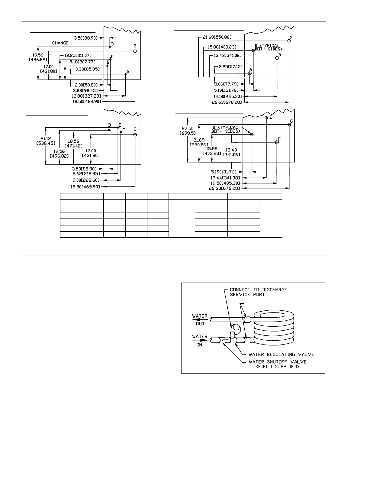
* A = Condenser In, B & C = Condenser Out, D = Condensate, all Female Pipe Thread, E = Liquid Refrigerant (field cut), F =
Refrigerant Discharge (field cut), G = Electrical Opening
Figure 5 Connection Locations
3.11 Check Compressor Spring Mounts
(008 & 012 size only)
90MU008/012 UNITS
-- -- -- -- (45)
Install water--regulating valve in water supply line
outside cabinet as follows.
The compressors are held rigid in shipment by bolts
extending through a washer, grommet and compressor
foot into a weld nut. Loosen each bolt (4 per
compressor) until compressor floats freely on springs.
SeeFigure5
Then re--tighten bolts until there is slight pressure on the
neoprene gasket. This will steady the compressor and
prevent start and stop rocking.
The compressors have reversible oil pumps that operate
in either direction; therefore, the direction of rotation
need not be checked.
3.12 Make Condenser Connections
UNIT MOUNTED CONDENSER (90MA/MF) -- Condenser
water inlet and outlet connections are shown in
Figure 5. Piping arrangements for condenser cooling
water are shown in Figure 6.
Connect condenser water supply and return lines as
indicated. When connecting water lines, hold the
condenser inlet and outlet stubs firmly with a wrench at
the female pipe thread hex fitting to prevent twisting.
Do not use water lines smaller than connection sizes
shown in Figure 5. Observeall applicableplumbing and
sanitary codes.
62--10458-- 00
Figure 6 Typical Condenser Water Piping
a. Route regulating valve capillary with its flare nut to
the port on refrigerant discharge line (Figure 1), using any convenient unused opening on side of unit.
Use a grommet in panel to prevent chafing of capillary.
b. Remove cap from discharge line fitting.
c. Remove cotter pin taped to discharge line fitting. In-
sert pin, split end first, into regulating valve flare.
6
Page 13
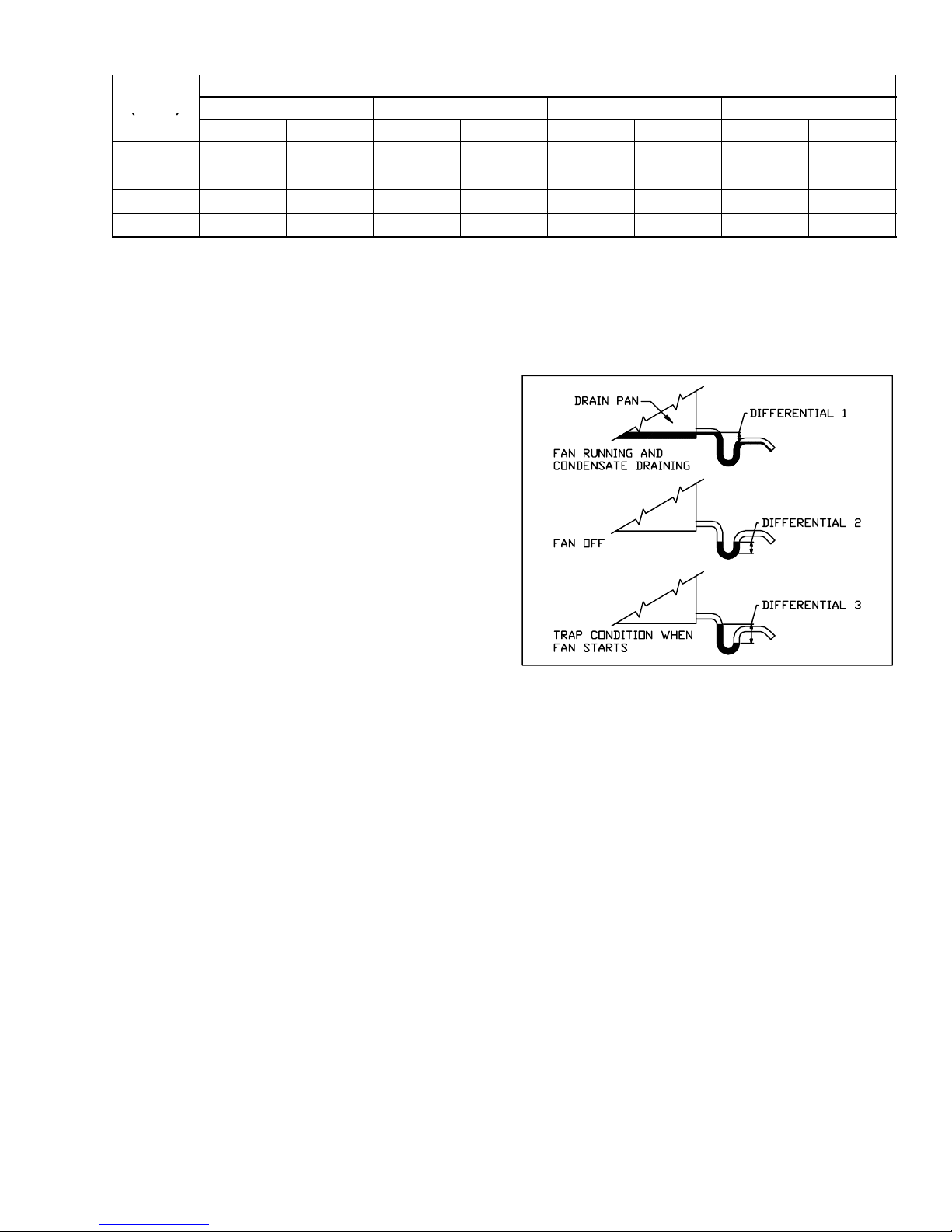
Table 4 Recommended Line Sizes, Remote Condenser
(
)
UNIT
(90MU)
0--25 26--50 51--75 76--100
DISCH LIQUID DISCH LIQUID DISCH LIQUID DISCH LIQUID
LENGTH OF RUN
004 1/2 (1.3) 1/2(1.3) 5/8(1.6) 1/2(1.3) 5/8(1.6) 1/2(1.3) 7/8(2.2) 1/2(1.3)
006 5/8(1.6) 1/2(1.3) 7/8(2.2) 1/2(1.3) 7/8(2.2) 1/2(1.3) 7/8(2.2) 1/2(1.3)
008 7/8(2.2) 5/8(1.6) 7/8(2.2) 5/8(1.6) 7/8(2.2) 5/8(1.6) 1-1/8(2.9) 5/8(1.6)
012 7/8(2.2) 5/8(1.6) 1-1/8(2.9) 5/8(1.6) 1-1/8(2.9) 5/8(1.6) 1-1/8(2.9) 5/8(1.6)
NOTES:
1. Line sizes given in inches (cm).
2. Line sizes should never be smaller than cooling unit connection size.
3. A nominal number of fittings has been considered in determining line sizes. Smaller line sizes may be considered
if run is simple and few fittings are used.
d. Hold flare tightly against fitting while connecting
flare nut. Round end of cotter pin will depress core of
fitting. The opened fitting allows refrigerant pressure
to act on water regulating valve. Tighten nut to prevent leakage. Fitting automatically seals when nut is
removed.
REMOTE MOUNTED CONDENSER (90MU) -- I n s t a l l
remote mounted condenser in accordance with the
installation instructions provided with condenser.
Connection l ocations for liquid and discharge lines are
shown in Figure 5. Recommended line sizes are given
in Table 4. Additional instructions can be found in
Carrier System Design Manual, Part 3, for standard
refrigeration piping techniques. On 008 and 012 size
units, secure discharge line to bracket at unit outlet
using proper clamp from supplied fastener package
Condenserless (90MU) units are shipped with a
refrigerant holding charge. After refrigerant
connections are made, leak test, reclaim refrigerant,
evacuate, and charge system as described in paragraph
5.9.
3.13 Install Condensate Drain Line
Install a trapped condensate drain line at unit drain
connection. The drain requires standard pipe connected
to condensate pan nipple(s). F igure 7 shows proper trap
design.
Determine design negative static pressure. This
pressure is not the same as fan total static pressure,
which includes pressure losses downstream as well as
upstream from the evaporator air fan. Always assume
the worst conditions, such as having return air filters
clogged with debris.
Referring to Figure 7, differential 1 must be equal to or
larger than negative static pressure at design operating
condition. Store enough water in trap to prevent losing
seal. Differential 2 must be equal to or larger than
one--half the maximum negative static pressure. To
avoid loss of seal when the fan starts, differential 3 must
be greater than the maximum negative static pressure.
Figure 7 Condensate Drain Trap
Do not use drain line smaller than 3/4 inch. Use hole(s)
provided in panel for drain line. Pitch drain line
downward toward scupper. Installation of a plugged tee
is recommended for cleaning. Fill trap with water t o
make an air seal. Observe all sanitary requirements.
3.14 Make Electrical Connections
GENERAL -- Provide an adequate fused disconnect
switch within sight of the unit. Provision for locking
switch open (OFF) is advisable to prevent power from
being turned on when unit is being serviced.
POWER WIRING -- Conduit opening for all units is on left
side of unit near control box. Connect field power wires
at the compressor contactor.
Supply voltage must be in accordance with nameplate
voltage. Voltage between phases must be balanced
within 2% and current within 10% with compressor
running. Correct improper voltage or phase imbalance.
Unit failure as a result of operation on improper line
voltage or excessive phase imbalance constitutes abuse
and shall void the Carrier warranty. Use the following
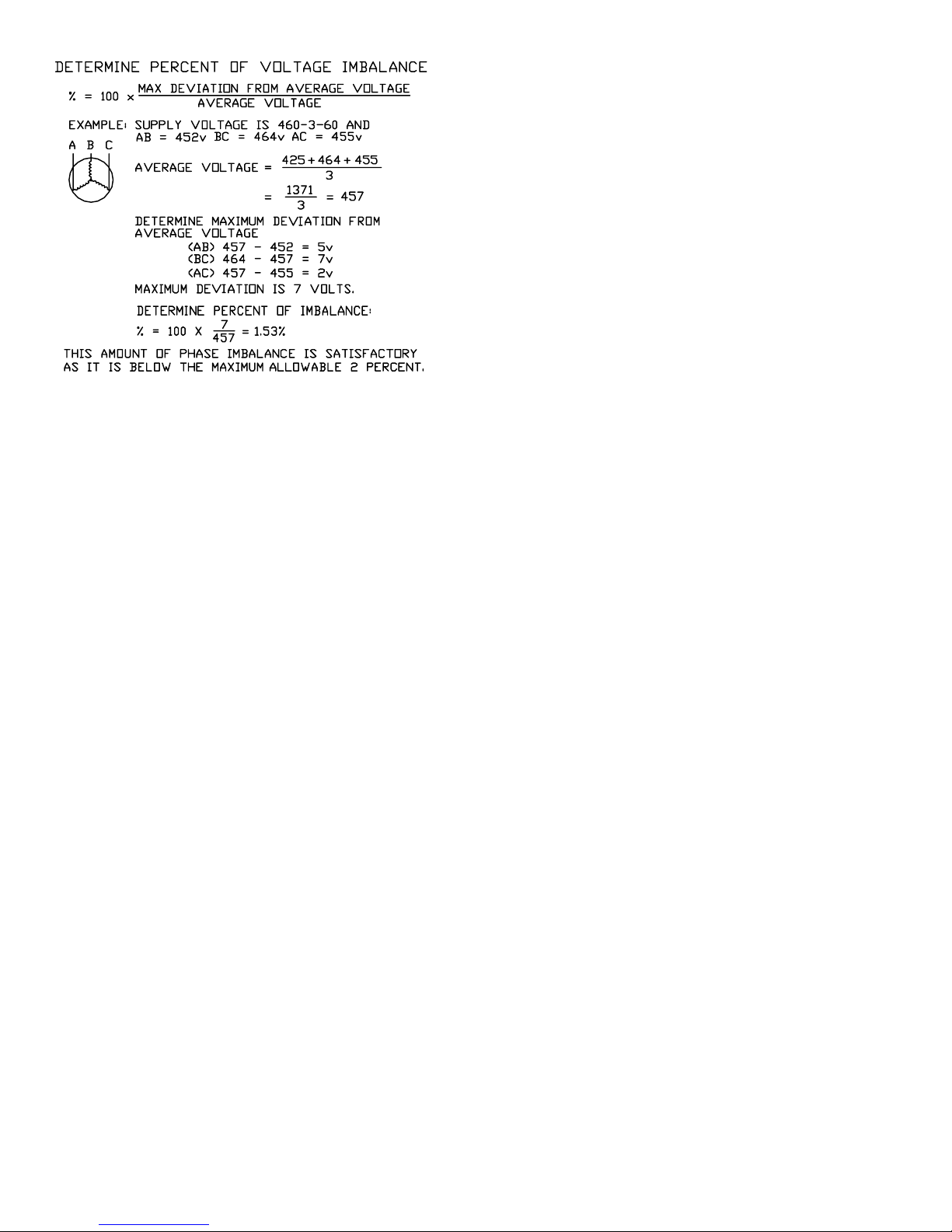
formula to determine the percent voltage imbalance.
7
62--10458-- 00
Page 14
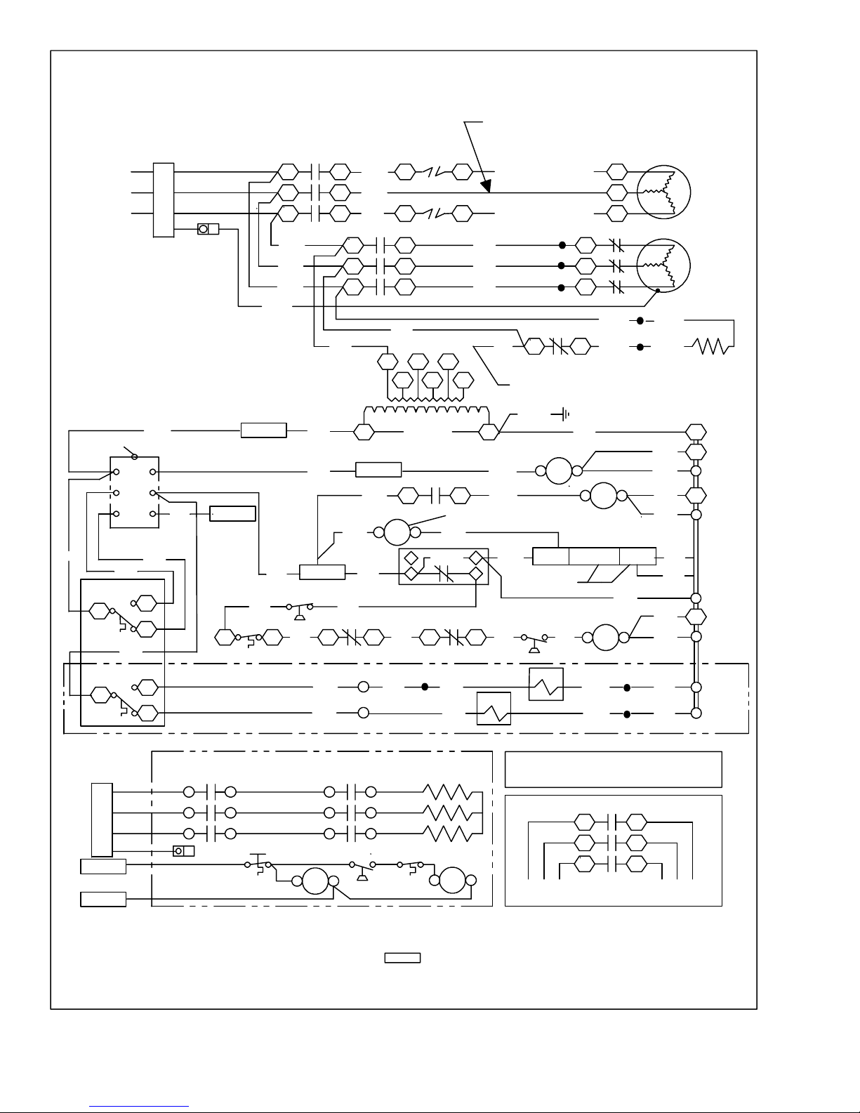
CONTROL WIRING -- On extended voltage (208/230--v)
units, the control transformer is factory wired for 208--v
usage. If unit is to be used on 230--v system, reconnect
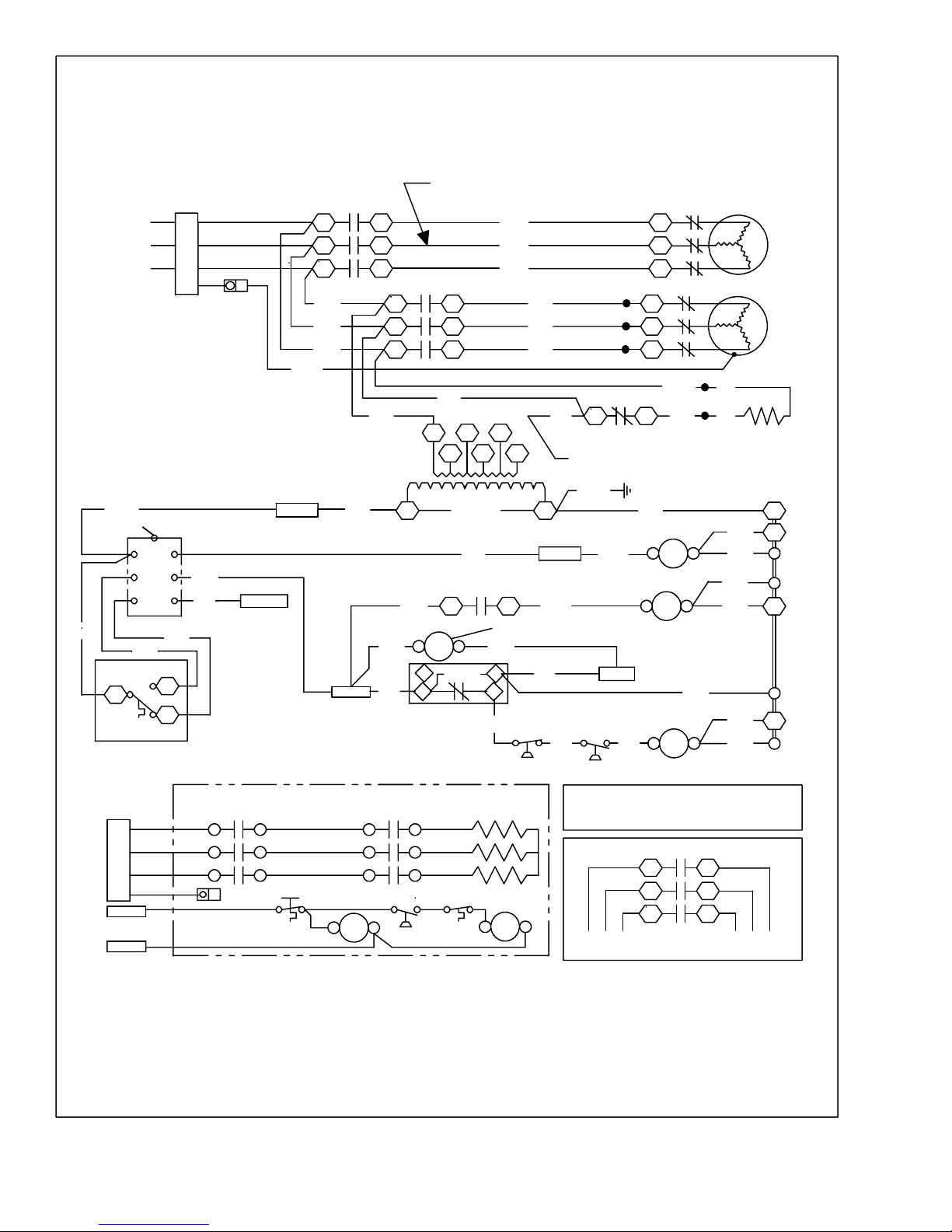
primary wiring on transformer. See Figure 13 (004/006
size) or Figure 15 (008/012 size).
On all units, the thermostat is factory installed. A
sensing element is provided in the return air. To wire
these units to a remote thermostat, or to a remote control
switch and thermostat, refer to unit Wiring Diagram or
contact your Carrier Transicold representative.
4. OPERATION
CAUTION
Compressor crankcase heater must be energized for 24 hours prior to start up to prevent
compressor bearing damage.
4.1 To Start Unit
a. Thoroughly inspect exterior of unit. Clean and dust
up debris, then wash with mild soap and water solution.
b. On 008 & 012 size units, ensure compressor dis-
charge, suction and liquid service valves are open.
The valves are accessible from the front of the unit.
To open valve, turn counterclockwise. After opening,
replace and tighten valve cap to prevent leakage.
Check oil level in compressor sight glass. If level is
below glass, add oil to bring level to approximately
1/4 glass. If level is above bottom of glass, do not remove any oil until the crankcase heater has been energized for at least twenty--four hours.
c. With selector switch in OFF position, turn main pow-
er on. Leave power on for 24 hours so that crankcase
heater can drive off accumulated refrigerant.
d. If desired, the selector switch may be placed in the
FAN position during the crankcase warm--up period.
On first start--up, check fan speed (Table 1 through
Table 2) and rotation (Figure 1). If fan requires adjustment, refer to paragraph 5.3.
e. Allow crankcase heater to remain energized (unit
power on) for at least 24 hours. Open any valves in
condenser cooling water supply lines and then set selector switch at COOL position. If room temperature
is above thermostat setting compressor will start. On
first start--up, set water regulating valve. (Refer to
paragraph5.7.)
f. S et thermostat for comfort as desired.
4.2 To Shut Down Unit
a. Turn selector switch t o OFF position. Do not shut off
main power except to service unit. The crankcase
heater is operative only when main power is on. (Refer to paragraph 5.12).
b. If unit is to be used for winter heating, set selector
switch at HEAT position and re--set thermostat at desired setting.
c. Ifunit may be exposed to freezing temperatures, drain
water from condenser and water piping. Add a noncorrosive antifreeze to residual water in system.
4.3 Sequence Of Operation
Unit operation is dependent on the position of the mode
selector switch. (See note 3, Figure 14
or Figure 16.)
Operation sequence for each switch position is provided
in the following paragraphs.
OFF POSITION: With correct voltage supplied at the
field power supply terminals, see
Figure 13 or Figure 15
power flows through normally closed crankcase heater
relay (CHR) contacts (CHR, 4/5) to energize the
crankcase heater (CH).
TO PLACE THE UNIT IN THE FAN MODE: The
switch (SW) is placed in the FAN position to supply 24
volt control power, to energize indoor fan contactor
(IFC). Energizing IFC closes contacts (IFC, 11/21,
12/22 & 13/23) to energize the motor. Operation of the
crankcase heater is maintained.
TO PLACE THE UNIT IN THE COOL MODE: The
switch (SW) is placed in the COOL position. With
thermostat (T--LOW) calling for cooling (closed to
contacts R & W) control power flows from TRAN
through T--LOW, SW and compressor l ockout (CL)
normally closed contacts to the discharge pressure
switch (DPS). On 008/012 size units, flow continues
through the compressor internal protector (IPC),
compressor overloads (OLA & OLB) and the suction
pressure switch (SPS), to energize CHR. On 004/006
size units, flow continues directly thorough the suction
pressure switch to energize CHR.
Energizing CHR opens contacts C HR 4--5 to
de--energize CH and closes contacts CHR 1--3 and
energize the compressor contactor(CC). Energizing CC
closes its contacts to start the compressor motor (C).
Operation of the indoor fan motor (IFM) is maintained.
On 90MU units, power also flows from terminal TB1--5
to energize condenser fan relay (CFR). Energizing CFR
closes its contacts to supply power to the field supplied
condenser fan relay.
012 size units arefitted with a two stage cooling system.
On these units, if thermostat switch T--HIGH is also
calling for cooling, power flows through thermostat
62--10458-- 00
8
Page 15
switch T--HIGH to energize liquid line solenoid (LLS)
[to activate the full evaporator coil and all compressor
cylinders]. If thermostat switch T--HIGH is not calling
for cooling, power flows to energize compressor
unloader solenoid (US) [to unload compressor
cylinders].
When room temperature falls to the cutout point of
T--LOW, switch T--LOW opens to de-- energize CHR,
stopping the compressor motor and energizing CH. The
machine enters a stand--by state, ready to restart
automatically on room thermostat call for cooling.
If any safety device opens (CLO, SPS, DPS, IP, OLAor,
OLB) relay CHR is de--energized, stopping the
compressor motor and energizing the crankcase heater.
TO PLACE THE UNIT IN THE HEAT MODE: The
switch (SW) is placed in the HEAT position. With
thermostat (T--LOW) calling for heating (closed to
contacts R & B), 24 volt control power flows through
manual reset temperature cutout MC to energize safety
relay H2. Power also flows through air flow switch (AS)
and automatic cutout (AC) to energize operating relay
(H1). Energizing relays H1 and H2 closes contacts to
energize the heaters.
Placing SW in the FAN position de--energizes all
cooling or heating control circuits in the same manner as
activation of a safety switch. Placing SW in the OFF
position also de--energizes IFC to stop the indoor fan
motor.
5. SERVICE
WARNING
Never reach into unit while fan is running.
Lock open and tag unit disconnect before
working on fan. Remove fuses and take them
with you after noting this on tag.
5.2 Access Panel Removal
a. Remove return--air grille as described above.
b. Remove the panel fastening screws now exposed.
c. Pull out and down to remove top panel.
d. Pull out and up to remove bottom panel.
5.3 Evaporator Fan Adjustment
WARNING
Never reach into unit while fan is running.
Lock open and tag unit disconnect before
working on fan. Remove fuses and take them
with you after noting this on tag.
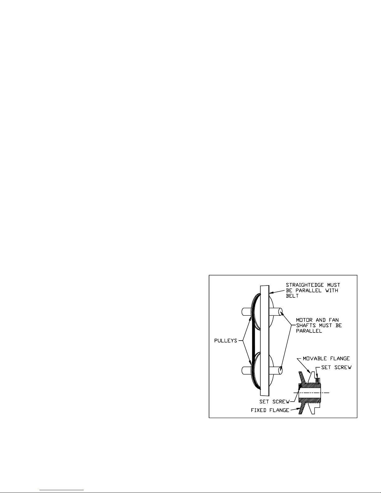
SPEED ADJUSTMENT -- The fan motor pulleys are
factory set at the fan speeds listed in Table 1, Table 3 or
Table 2. to change fan speed, do the following:
a. S hut off unit power supply.
b. Loosen fan belt by loosening fan motor from mount-
ing bracket.Do not loosen fan motor mounting brack-
et from unit.
c. Loosen movable pulley flange set screw (Figure 8).
d. Screw movable flange toward fixed flange to increase
fan speed and away from fixed flange to decrease
speed. Increasing fan speed increases load on motor.
Do not exceed maximum allowable fan speed or mo-
tor full load amps indicated on motor nameplate.
e. Set movable flange set screw at nearest flat of pulley
hub and tighten set screw.
f. Check pulley alignment and belt tension adjustment
as described below.
g. Check fan operation. Repeat above procedure as re-
quired.
CAUTION
Sharp edges of coil fins are exposed. To prevent injury, cover top of evaporator with
cardboard or a few l ayers of heavy tape.
CAUTION
To avoid coil damage, cover evaporator face
with plywood or other rigid sheet material.
If any coil fins are mashed or bent, straighten with a coil fin comb of the proper tooth
spacing (refer to “coil fins/inch” in Table 1
through Table 2). Check for refrigerant
leaks.
5.1 Return--Air Grille Removal
a. Pull grille out from top.
b. Pull grille up to release hinge pins from lower panel.
c. To reassemble, reverse procedure.
Figure 8 Fan Pulley Adjustment
PULLEY ALIGNMENT -- Shut off unit power supply.
Loosen fan motor pulley set screws and slide fan pulley
along fan shaft. Make angular alignment by loosening
motor from mounting bracket (See Figure 8).
9
62--10458-- 00
Page 16
BELT TENSION ADJUSTMENT -- Shut off unit power
supply. Loosen fan motor from mounting bracket. Do
not loosen motor mounting bracket from unit. Move fan
motor up or down until proper belt tension is achieved
(approximately 3/4--i n. deflection with 8--pound
tension at midpoint of belt span).
Lubrication -- Fan motor and fan shaft bearings are
lubricated for the life of the bearings. No re--lubrication
is required
5.4 Return--Air Filter
Inspect filters twice monthly and clean as required by
operating conditions. Filter size and type are listed in
Table 1, Table 3 or Table 2. To clean filters flush with
hot water or steam or soak in a mild water solution of
soap or detergent. Refer to filter manufacturer’s
instructions as applicable. Do not operate unit without
return--air filters in place.
5.5 Condensate Drain
Clean the drain line and unit drain pan at the start of each
cooling season. Check flow by pouring water into drain.
Be sure trap is filled as shown in Figure 7 to maintain an
air seal.
5.6 Evaporator Coil
WARNING
Never reach into unit while fan is running.
Lock open and tag unit disconnect before
working on fan. Remove fuses and take them
with you after noting this on tag.
spring tension, decrease water flow and increase pressure.
If pressure reading is above operating range, rotate
the square head adjusting screw clockwise; this will
decrease spring tension, increase water flow and decrease pressure.
c. Only the water regulating valve opening point is ad-
justable. The closing point is 3 to 7 psig below the
opening point and is non--adjustable.
5.8 Condenser
Condensers may require cleaning of water--deposited
scale.
WARNING
Follow all Safety codes. Wear safety glasses
and rubber gloves when using inhibited hydrochloric acid solution.
Clean condensers with an inhibited hydrochloric aci d
solution. The acid can stain hands and clothing, attack
concrete and, without inhibitor, can attack steel. Cover
surroundings to guard against splashing. Vapors from
vent pipe are not harmful, but take care to prevent liquid
from being carried over by the gases.
Warm solution acts faster, but cold solution is just as
effective if applied for a longer period.
Remove dirt and debris from evaporatorcoil as required
by condition. Clean coil with a stiff brush, vacuum
cleaner or compressed air. Use a fin comb of the correct
tooth spacing (Refer to
Table 1, Table 3 or Table 2 for
coil fins/inch) when straightening mashed or bent coil
fins.
5.7 Water Regulating Valve
PREPARATION FOR OPERATION.
a. Open the water regulating valve inlet and outlet isola-
tion valves.
b. Close the water regulating valve bypass valve.
ADJUSTMENT
a.
The compressor discharge pressure is controlled by
the water regulating valve and may be monitored by
observing liquid line pressure.
NOTE
Adjustments to the water regulating valve must
be made slowly, allowing ample time for response and stabilization.
b. Install a calibrated gauge at the liquid line service
port. Operatingliquid line rangefor R--22 units is 250
to 270 psig (1724 to 1862 kPa), for R--134a units is
155 to 180 psig (1069 to 1241 kPa) and for R--407C is
267 to 288 psig (1841 to 1986 kPa). If pressure reading is below operating range, rotate the square head
adjusting screw counterclockwise; this will increase
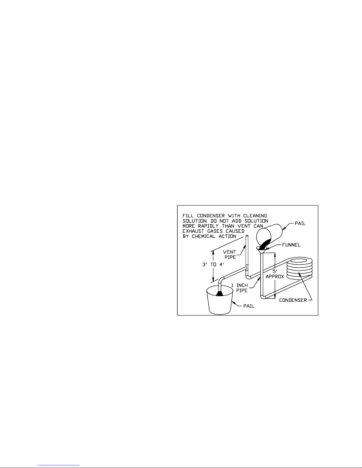
Figure 9 Gravity Flow Method
GRAVITY FLOW METHOD
a. Disconnect condenser piping at unit, including isola-
tion valves and water regulating valve.
b. Fill condenser as shown in Figure 9. Follow acid
manufacturer’s instructions. When condenser is full,
allow solution to remain overnight
c. Drain condenser and flush with clean water.
FORCED CIRCULATION METHOD
a. Disconnect condenser piping at unit, including isola-
tion valves and water regulating valve.
b. Fill system as shown in Figure 10. Follow acid
manufacturer’s instructions. Fully open vent pipe
when filling system. The vent may be closed when
system is full and pump is operating.
62--10458-- 00
10
Page 17
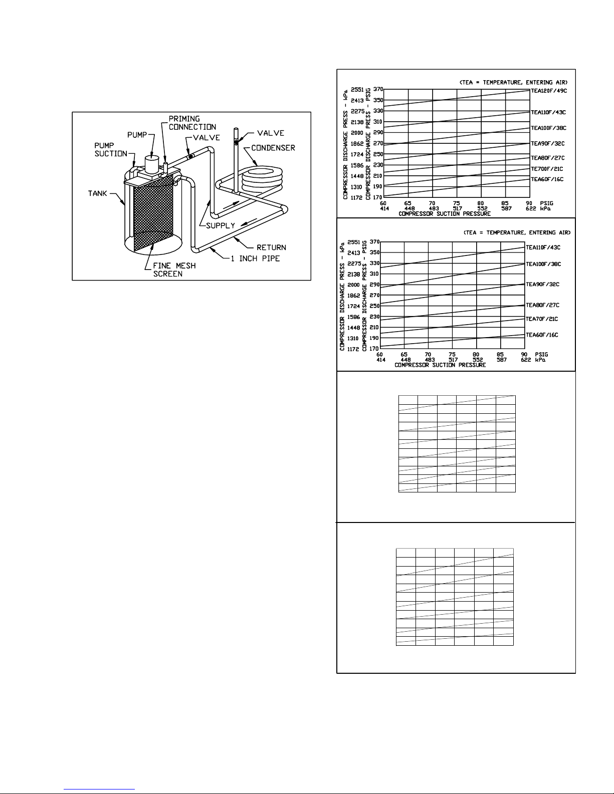
c. Regulate flow to condenser with a supply line valve.
If pump is a non--overloading type, the valve may be
fully closed while pump is running. For average scale
deposit, allow solution to remain in condenser overnight. For heavy scale deposit, allow 24 hours.
d. Drain condenser and flush with clean water.
Figure 10 Forced Circulation Method
5.9 Refrigerant Charging
90MA/MF --
These units are shipped with a full
operating charge. If recharging is necessary (complete
chargelost), weigh in amount of refrigerant indicated on
unit nameplate and in
Table 1, Table 3 or Table 2.
If unit has partial charge, it must be recharged by
removing existing charge and recharging by weighing
in the required amount of refrigerant.
90MU004 & 006 -- These units, used with remote
condensers, are shipped with a holding charge only. To
charge:
a. Open discharge and liquid service valves.
b. Leak test, reclaim refrigerant and evacuate.
c. Using standard refrigerant charging techniques and
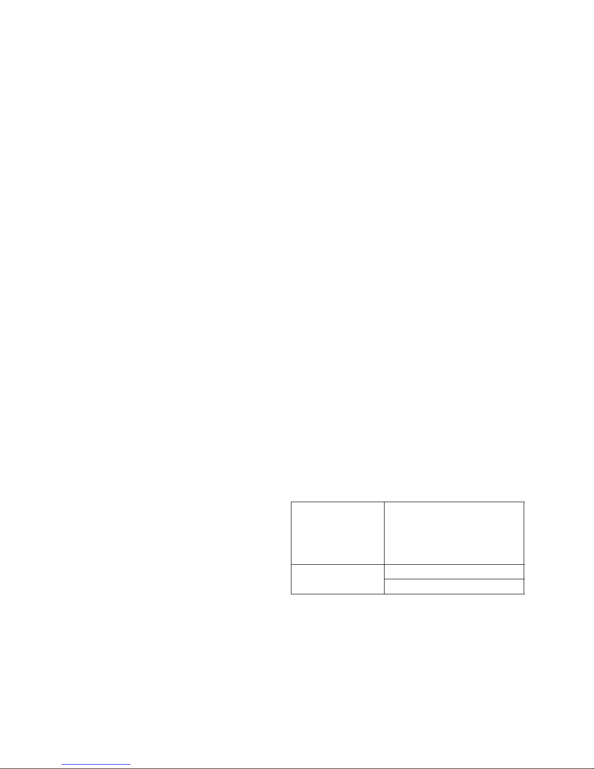
charging charts (Figure 11) add refrigerant as required to maintain proper operating conditions.
90MU008 & 012 -- These units, used with remote
condensers, are shipped with a holding charge only. To
charge:
a. Open discharge line, liquid line, compressor dis-
charge and compressor suction service valves.
b. Leak test, reclaim refrigerant and evacuate.
c. Add sufficient refrigerant vapor to permit continuous
operation after starting unit.
d. Start unit. Using standard charging techniques, add
refrigerant as required to maintain normal operating
conditions. Use charging chart supplied with condenser, if available. If information is not available,
block off enough of condenser or set water regulating
valve as applicable to maintain a discharge pressure
of 220 psig (1517 kPa) for R--22 units or 233 psig
(1607 kPa) for R--407C units. Charge to a clear sight
glass.
90MU004 UNITS R--22
90MU006 UNITS R--22
90MU004 UNITS R--407C
2758
400
2620
380
2482
360
2344
340
2206
320
2069
300
1930
280
260
1793
1655
240
1517
220
1379
1241
200
COMPRESSOR DISCHARGE PRESS -- PSIG
180
70 75 80 85 90 95 100
483 517 552 587 655622 690
COMPRESSOR SUCTION PRESSURE
COMPRESSOR DISCHARGE PRESS -- kPa
90MU006 UNITS R--407C
2758 400
2620
380
2482
360
2344
340
2206
320
2069 300
1930
280
1793
260
1655
240
1517
220
1379 200
180
1241
COMPRESSOR DISCHARGE PRESS -- PSIG
COMPRESSOR DISCHARGE PRESS -- kPa
70
75 80
517483
COMPRESSOR SUCTION PRESSURE
Figure 11 Charging Charts
(TEA = TEMPERATURE, ENTERING AIR)
(TEA = TEMPERATURE, ENTERING AIR)
552
85
587
90
622
95
655
100
690
TEA120F/49C
TEA110F/43C
TEA100F/38C
TEA90F/32C
TEA80F/27C
TEA70F/21C
TEA60F/16C
PSIG
kPa
TEA110F/43C
TEA100F/38C
TEA90F/32C
TEA80F/27C
TEA70F/21C
TEA60F/16C
PSIG
kPa
11
62--10458-- 00
Page 18
5.10 Evaporator Fan Motor Removal
a. S hut off unit main power supply.
WARNING
Lock open and tag unit disconnect before
working on fan motor. Remove fuses and
take them with you after noting this on tag.
CAUTION
Before attempting to re move fan motors or
motor mounts, place a piece of plywood over
evaporator coils to prevent coil damage.
b. Loosen motor hold down bolts on mounting bracket
so that fan belt can be removed. Motor power wires
need not be disconnected from motor terminals before motor is removed from unit.
c. Loosen but do not remove the 2 motor mounting
bracket bolts on left side of bracket.
d. Slide motor/bracket assembly to extreme right, re-
move bolts and lift out through space between fan
scroll and side. Rest motor on a high platform such as
a step l adder. Do not allow motor to hang by its power
wires.
5.11 Pressure Relief Device
All units are equipped with a fusible--plug type safety
relief device on the refrigerant tubing. The relief setting
is 197 _F to 203 _F on all units.
5.12 Crankcase Heater
A crankcase heater is supplied on the 008 & 012 size
units and on all 134a units. The heater prevents liquid
refrigerant from accumulating in the compressor
crankcase during extended shutdown periods. Heater is
automatically energized whenever unit main power is
on and compressor is stopped. Heater is de--energized
when compressor starts.
Do not shut off main power supply for an extended
period except for servicing unit. Turn on power supply
for at least 24 hours after an extended shutdown before
starting compressor. Refer to “Operation”.
5.13 Cycle--LocTM-- Protection Device
All units are equipped with Cycle--LOC
current--sensing lockout relay. This device will lock out
the compressor after any safety trip (discharge pressure
switch, suction--pressure switch, or internal overload of
the compressor). Check reason for lockout before
resetting the device. Refer to unit label wiring diagram.
To reset, turn the system switch to OFF, then back to
COOL.
5.14
Discharge and Suction Pressure Switches
Refer to Table 1 through Table 2 for opening and
closing settings for these safety devices.
The discharge pressure switch is located on the
compressor on the 008 & 012 size units and on the
discharge line on all other units. The suction pressure
switch is locat ed on top of the compressor on 06DR
compressor equipped units and on the suction line on all
other units.
5.15 Oil Charge
All units are factory charged with oil. On 06D
compressors, observe the oil level in the sight glass at
start--up. If unit oil level is below sight glass, add oil
until level reaches approximately 1/4 sight glass.
If oil charge is above sight glass, do not remove any oil
until the compressor crankcase heater has been
energized for at least 24 hours.
When additional oil or a complete charge is required,
use only the following C arrier approved oil.
R--22 Units
Design Series One 204/206 size units
Witco part number 999--5170--55
Design Series One 208/212 size units and all Design
Series Two
Witco -- Suniso 3GS
Calumet -- RO--15
R--134a Units
Castrol -- Icematic E68
ICI -- Emkarate RL68HP
R--407C Units
004 and 006
Copeland Ultra 22CC
Mobil Artic EAL 22CC
ICI (Virginia KMP) Emkarate
RL32C
Thermal Zone 22CC
Castrol -- Icematic E68
008 and 012
ICI -- Emkarate RL68HP
62--10458-- 00
12
Page 19
W
V
T
S
R
P
N
M
L
K
0.70
10.00
15.00
7.50
5.00
1.00
2.00
8.75
2.56
3.18
--
15.38
16.50
6.00
9.00
--
--
--
--
--
--
J
25.81
--
H
0.75
G
23.31
18.005
--
F
45.50
--
E
A
1.25
D
36.25
48.00
C
38.25
50.00
B
22.00
27.31
40.25
52.00
Figure 12 Mounting Base
13
USED ON A
004/006 SIZE
008/012 SIZE
BASED ON DRAWING 50BW400093
62--10458-- 00
Page 20
FIELD
POWER
SUPPLY
RED
RED
T--LOW
R
NO
NC
NO
ORN
L1
L2
L3
G
(SEE NOTE 3)
SW
ORN
YEL
YEL
W
B
GROUND
TB1-- 4
GRN
F
11
12
13
YEL
BLU
BLK
CC
RED
TB1-- 5
21
22
23
BLK
RED
11
12
13
TRAN
RED
CL
WIRE PASSES THOUGH LOOP OF CL
BLK
BLU
YEL
IFC
21
22
23
BLU CHR
H1
H2H3H4
24VOLT
VIO
CHR
RED
1 3
CFR
LOGIC
X
2
RED
YEL
BLU
BLK
BLU 4
H5
H6
90MU UNITS ONL Y
BRN
1
3
DPS
SEE NOTE 1
X2X1
TB1-- 1
RED
BRN TB1--3
BLU
GRN
SPS
RED
BLU
IPC
1
2
3
IPF
T3
T2
T1
ORN
5
VIO
BRN
IFC BRN
CC BRN
BRN
CHR BRN
BLK
BLK
BRN
BRN
BRN
C
IFM
CH
C2 CC
C2
C2
CHR
CC
TRAN
IFC
CHR
CL1
IFC
OPTIONAL ELECTRIC DUCT HEATER
H2
L1
L2
L3
G
TB1-- 4
TB1-- 3
GROUND
MC AS AC
Figure 13 Wiring Schematic -- 90MA/MF/MU004/006
62--10458-- 00
H2
H1
14
HEATERS
H1
FOR HOT WATER/STEAM
HEAT SEE NOTE 2
90MU CONDENSER FAN WIRING
11
12
13
SHIPS POWER
SINGLE OR THREE PAHSE AS REQUIRED
CFR
21
22
23
TO FAN
Page 21
11
21
C1
221223
IFC
13
C2
CONTROL BOX
11
12 13 H1 H3 H2 H4
X2 X1
22
21
C1
CC
23
C2
TRAN
F
CONTROL PANEL
COOL
FAN
B
OFF
B
HEAT
R
M
A
A
W
C
A
E
R
R
O
E
L
O
DT1 DT2 DT1
TB1
1
CLO
2X
1
3
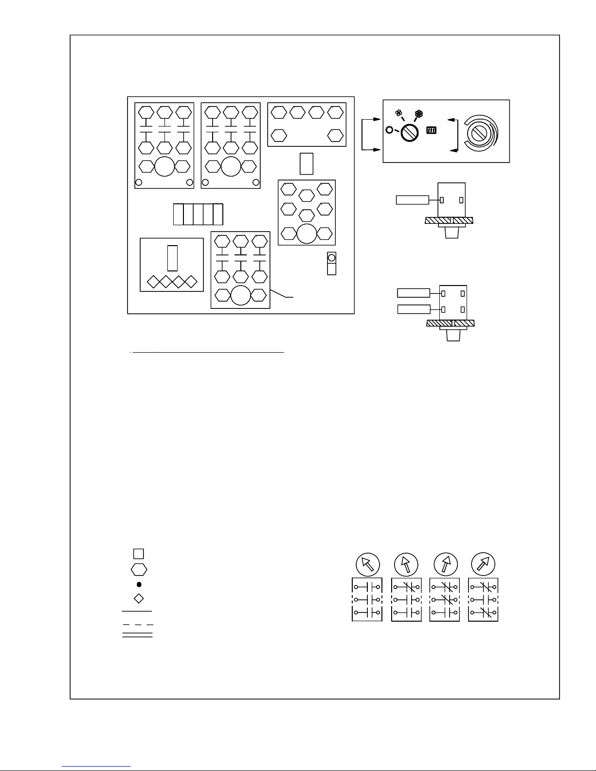
LEGEND
AS
AIR SWITCH
AUTOMATIC CUTOUT
AC
C
COMPRESSOR
CC
COMPRESSOR CONTACTOR
CRANKCASE HEATERCH
CFR CONDENSER FAN RELAY
CHR CRANKCASE HEATER RELAY
CL
COMPRESSOR L OCKOUT
DPS
DISCHARGE PRESSURE SWITCH
F
FUSE
H1 CONTROLLING HEAT CONTACTOR
BACKUP HEAT CONTACTOR
H2
IFC
INDOOR FAN CONTA CTOR
IFM
INDOOR FAN MOTOR
IPC
INTERNAL PROTECTOR-- COMPRESSOR
IPF INTERNAL PROTECTOR-- FAN MOTOR
MC MANUAL (RESET) CUTOUT
SPS
SUCTION PRESSURE SWITCH
SW
SWITCH
T THERMOSTAT
TB
TERMINAL BOARD
TRAN
TRANSFORMER
TERMINAL BOARD TERMINAL
TERMINAL (MARKED)
TERMINAL/SPLICE (UNMARKED)
LOCKOUT TERMINAL
FACTORY WIRING
FIELD WIRING
INDICATES COMMON POTENTIAL,
DOES NOT REPRESENT WIRING
5432
C1
11
21
DT2
221223
CFR
13
C2
1
2
4
5
CHR
C1
GROUND
90MU ONLY
3
6
TB1-- 1
C2
TB1-- 5
TB1-- 4 NC
NO
VIEW A--A
NO
VIEW B -- B
NOTES:
1. 208--230/3/60 VOLT UNITS FACTORY WIRED
TO TRANSFORMER TERMINAL H2 (208 VOLT
TAP). FOR 230 VOLT APPLICATIONS, RE--CONNECT TO TERMINAL H3 (230 VOLT TAP).
460/3/60 VOLT UNITS FACTORY WIRED TO
TERMINAL H6. 400/3/50 VOLT UNITS FACTORY
WIRED TO TERMINAL H5.
2. CONNECTION POINTS AT TB--1 TERMINALS
3 & 4 MAY BE USED FOR HEAT CONTROLS.
MAXIMUM LOAD IS 250 VA INRUSH, 50 VA
SEALED.
3. SWITCH CONTACT ARRANGEMENT IS AS
SHOWN BELOW.
FANOFF
HEATCOOL
Figure 14 Component Arrangement -- 90MA/MF/MU004/006
15
62--10458-- 00
Page 22
FIELD L1
POWER
SUPPLY
RED
T--LOW
R
T--HIGH
R
NO
NC
NO
ORN
ORN
L2
L3
G
GROUND
RED
(SEE NOTE 3)
SW
YEL
YEL
W
B
W
B
11
12
13
YEL
BLU
BLK
GRN
TB1-- 4
ORN
DPS
BLK BLK
IPC
9
90MA012 UNITS ONLY
8
CC
RED
VIO
TB1-- 5
2
BLU
BLK
21
22
23
BLK
11
12
13
TRAN
RED
OLA
CDT1
CDT2
BLK
BLU
YEL
IFC
TB1-- 1
RED
CL
RED
1
4 3
4 3
21
22
23
BLU
H1
H2H3H4
24VOLT
1 3
CFR
X
2
BLU
WIRE PASSES THOUGH
LOOP OF CL
OLB
OLA
YEL
BLU
BLK
H5
H6
X2X1F
CHR
90MU UNITS ONL Y
BRN
LOGIC
1
3
OLB
2
1
BLU
BLK
(COLOR VARIES)
(COLOR VARIES)
CHR
4
BLU
SEE NOTE 1
GRN
RED
RED
BRN
BLU
US
IFC
TB1-- 3
90MA012
UNITS ONLY
SPS
BLUREDRED
LLS
T3
T2
T1
ORN
5
VIO
BRN
CC
JUMPER
CHR
BLU
BLK
1
2
3
IPF
BRN
TB1-- 2
C
IFM
BLK
BLK
CH
CC
C2
C2
C2
1
CHR
CC
TRAN
US
LLS
CHR
CLBRN
TB1-- 2
TB1-- 2
BRN
BRN
BRN
BRN
BRN
BRN
BRN IFC
BRN
BRN
IFC
OPTIONAL ELECTRIC DUCT HEATER
H2
L1
L2
L3
G
TB1-- 4
TB1-- 3
GROUND
MC
Figure 15 Wiring Schematic -- 90MA/MF/MU008/012
62--10458-- 00
H2
H1
AS AC
16
HEATERS
H1
FOR HOT WATER/STEAM
HEAT SEE NOTE 2
90MU CONDENSER FAN WIRING
11
12
13
SHIPS POWER
SINGLE OR THREE PAHSE AS REQUIRED
CFR
21
22
23
TO FAN
Page 23
11
21
C1
221223
IFC
13
C2
CONTROL BOX
11
12 13 H1 H3 H2 H4
X2 X1
21
C1
22
CC
23
C2
TRAN
F
CONTROL PANEL
COOL
FAN
B
OFF
B
HEAT
R
M
A
W
A
C
A
E
R
R
O
E
O
L
DT1 DT2 DT1
TB1
1
CLO
2X
1
3
LEGEND
AS
AIR SWITCH
AUTOMATIC CUTOUT
AC
C
COMPRESSOR
CC
COMPRESSOR CONTACTOR
CRANKCASE HEATERCH
CFR CONDENSER FAN RELAY
CHR CRANKCASE HEATER RELAY
CL
COMPRESSOR L OCKOUT
DT
DUMMY TERMINAL
DISCHARGE PRESSURE SWITCH
DPS
F
FUSE
H1 CONTROLLING HEAT CONTACTOR
BACKUP HEAT CONTACTOR
H2
IFC
INDOOR FAN CONTA CTOR
IFM
INDOOR FAN MOTOR
IPC
INTERNAL PROTECTOR-- COMPRESSOR
IPF
INTERNAL PROTECTOR-- FAN MOTOR
LLS LIQUID LINE SOLENOID
OL OVER LOAD
MC MANUAL (RESET) CUTOUT
SPS
SUCTION PRESSURE SWITCH
SW
SWITCH
T THERMOSTAT
TB
TERMINAL BOARD
TRAN
TRANSFORMER
US UNLOADER SOLENOID
5432
11
21
C1
DT2
221223
CFR
13
C2
1
4
C1
GROUND
3
2
6
5
CHR
C2
90MU ONLY
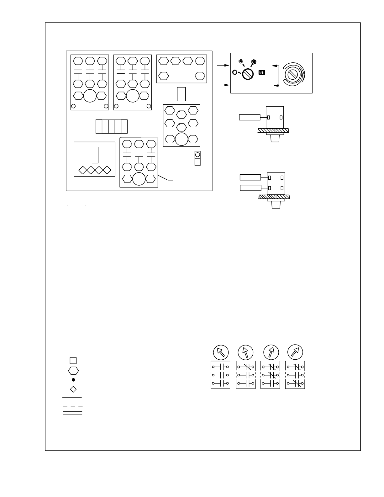
NOTES:
1. 208--230/3/60 VOLT UNITS FACTORY WIRED
TO TRANSFORMER TERMINAL H2 (208 VOLT
TAP). FOR 230 VOLT APPLICATIONS, RE--CONNECT TO TERMINAL H3 (230 VOLT TAP).
460/3/60 VOLT UNITS FACTORY WIRED TO
TERMINAL H6. 400/3/50 VOLT UNITS FACTORY
WIRED TO TERMINAL H5.
2. CONNECTION POINTS AT TB--1 TERMINALS
3 & 4 MAY BE USED FOR HEAT CONTROLS.
MAXIMUM LOAD IS 250 VA INRUSH, 50 VA
SEALED.
3. SWITCH CONTACT ARRANGEMENT IS AS
SHOWN BELOW.
TB1-- 1 NO
VIEW A--A
TB1-- 5
TB1-- 4 NC
NO
VIEW B -- B
TERMINAL BOARD TERMINAL
TERMINAL (MARKED)
TERMINAL/SPLICE (UNMARKED)
LOCKOUT TERMINAL
FACTORY WIRING
FIELD WIRING
INDICATES COMMON POTENTIAL,
DOES NOT REPRESENT WIRING
Figure 16 Component Arrangement -- 90MA/MF/MU008/012
17
FANOFF
HEATCOOL
62--10458-- 00
Page 24

A
M
Access Panel, 9
Accessory Plenum, 1
Air Filter, 5, 10
C
Component Arrangement, 15, 17
Condensate Drain, 7, 10
Condenser, 10
Condenser Connections, 6
Crankcase Heater, 12
Cycle--Loc, 12
E
Electrical Connections, 7
Evaporator Coil, 10
Model Chart, 1
Mounting Base, 13
O
Oil Charge, 12
P
Pressure Relief Device, 12
Pressure Switches, 12
R
Refrigerant Charging, 11
Remote Condenser, 7
Return Air, 1
F
Fan Adjustment, 9
Fan Motor, 12
Fan Shaft, 5
H
Heating Coil, 1
I
Installation, 1
Introduction, 1
L
Line Sizes, 7
S
Sequence Of Operation, 8
Shut Down Unit, 8
Spring Mounts, 6
Start Unit, 8
V
Ventilation, 1
W
Water Regulating Valve, 10
Wiring Schematic, 14, 16
Index -- 1
62--10458-- 00
 Loading...