

Carrier 8000 58WAV User Manual
Weathermaker 8000^*^
HEATING & COOLING
Induced-Combustion Furnaces
Installation, Start-Up, and Operating Instructions
Sizes 045-155, Series 110
NOTE: Read the entire instruction manual before starting the
installation.
Index Page
SAFETY CONSIDERATIONS ............................................................................. 1
Clearances From Combustibles
......................................................................
1
INTRODUCTION...................................................................................................1-2
LOCATION ............................................................................................................... 3
General .................................................................................................................3
Relative to Cooling Equipment ....................................................................... 3
Hazardous Locations......................................................................................... 3
AIR FOR COMBUSTION AND VENTILATION
.........................................
3-4
Unconfined Space ...............................................................................................3
Confined Space .............................................................................................. 3-4
FILTER ARRANGEMENT ............................................................................... 4-5
LEVELING LEGS..................................................................................................5-6
GAS PIPING.......................................................................................................... 6-7
ELECTRICAL CONNECTIONS........................................................................7-8
115-v Wiring.........................................................................................................7
24-v Wiring...........................................................................................................8
Accessories........................................................................................................... 8
VENTING ................................................................................................................ 8
START-UP, ADJUSTMENT, AND SAFETY CHECK................................ 8-9
General .............................................................................................................. 8
Sequence Of Operation .................................................................................... 8
Heating Mode ..................................................................................................... 8
Cooling Mode
........................
,........................................................................... 8
Continuous Blower Mode ................................................................................ 8
Heat Pump Mode ........................................................................................... 8-9
START-UP PROCEDURES .................................................................................. 9
ADJUSTMENTS ................................................................................................ 9-13
Set Gas Input Rate ....................................................................................... 9-12
Set Temperature Rise ............................................................................... 12-13
Set Thermostat Heat Anticipator ................................................................. 13
CHECK SAFETY CONTROLS ......................................................................... 13
CHECKLIST .......................................................................................................... 13
Installing and servicing heating equipment can be hazardous due to
SAFETY CONSIDERATIONS
gas and electrical components. Only trained and qualified person
nel should install, repair, or service heating equipment.
Untrained personnel can perform basic maintenance functions
such as cleaning and replacing air filters. All other operations must
be performed by trained service personnel. When working on
heating equipment, observe precautions in the literature, on tags,
and on labels attached to or shipped with the unit and other safety
precautions that may apply.
Follow all safety codes. In the United States, follow all safety
codes including the National Fuel Gas Code NFPA No. 541992/ANSI Z223.1-1992 (NFGC). In Canada, refer to the current
edition of the National Standard of Canada CAN/CGA-B149.1and .2-M91 Natural Gas and Propane Gas Installation Codes
(NSCNGPIC). Wear safety glasses and work gloves. Have fire
extinguisher available during start-up and adjustment procedures
and service calls.
a
Recognize safety information. This is the safety-alert symbol ^ .
When you see this symbol on the furnace and in instructions or
manuals, be alert to the potential for personal injury.
Understand the signal word DANGER, WARNING, or CAU
TION. These words are used with the safety-alert symbol. DAN
GER identifies the most serious hazards which will result in severe
personal injury or death. WARNxNG signifies a hazard that could
result in personal injury or death. CAUTION is used to identify
unsafe practices which would result in minor personal injury or
product and property damage. NOTE is used to highlight sugges
tions that will result in enhanced installation, reliability, or
operation.
These instructions cover minimum requirements and conform to
existing national standards and safety codes. In some instances,
these instructions exceed certain local codes and ordinances,
especially those that may not have kept up with changing residen
tial construction practices. We require these instructions as a
minimum for a safe installation.
Table 1—Minimum Clearances From
Combustible Materials (In.)
UNIT SIZE
Sides Single-Wall Vent
Type B-1 Double-Wall Vent
Back
Top of Plenum
Vent Connector Single-Wall Vent
Type B-1 Double-Wall Vent 1 1
Front Single-Wall Vent 6
Type B-1 Double-Wall Vent
NOTES;
1. Provide 30-in. front clearance for servicing. An open door in front of the
furnace can meet this requirement.
2, A minimum clearance of 3 in. must be provided in front of the furnace for
combustion air and proper operation.
INTRODUCTION
The Model 58WAV, Series 110 Furnaces are available in sizes
45,000 through 155,000 Btuh input capacities.
The design of the upflow gas-fired furnace is A.G.A./C.G.A.
certified for natural and propane gas and for installation on
combustible flooring, in alcoves, attics, basements, closets, or
utility rooms. The design of this furnace line is not A.G.A./C.G.A.
certified for installation in mobile homes, recreation vehicles, or
outdoors.
EFFICIENCY
RATING
CERTIFIED
ama
Service 30
58WAV
045 AND 070
1
0
0 0
1 1
6 6
3 3
091-155
0
0
6
30
Manufacturer reserves the right to discontinue, or change at any time, specifications or designs without notice and without incurring obligations.
BookI 1 I 4 PC 101 Catalog No. 535-850 Printed in U.S.A. Form 58WAV-2SI Pg 1 10-93 Replaces; 58WAV-1S1
Tab |6a|8a
39-7/8
-28-1/2
7/8 DIA '-—»LL
ACCESSORY
1-3/4 DIA HOLE
GAS ENTRY
1/2 DIA HOLE"
THERMOSTAT
WIRE ENTRY
H3/16
2-3/8
—-1-1/2 DIA
^ R.H. GAS ENTRY
7/8 DIA
ACCESSORY
1/2 DIA
THERMOSTAT
WIRE ENTRY
-13/16
SIDE INLET
11/16-
24-5/16 11/16-*-
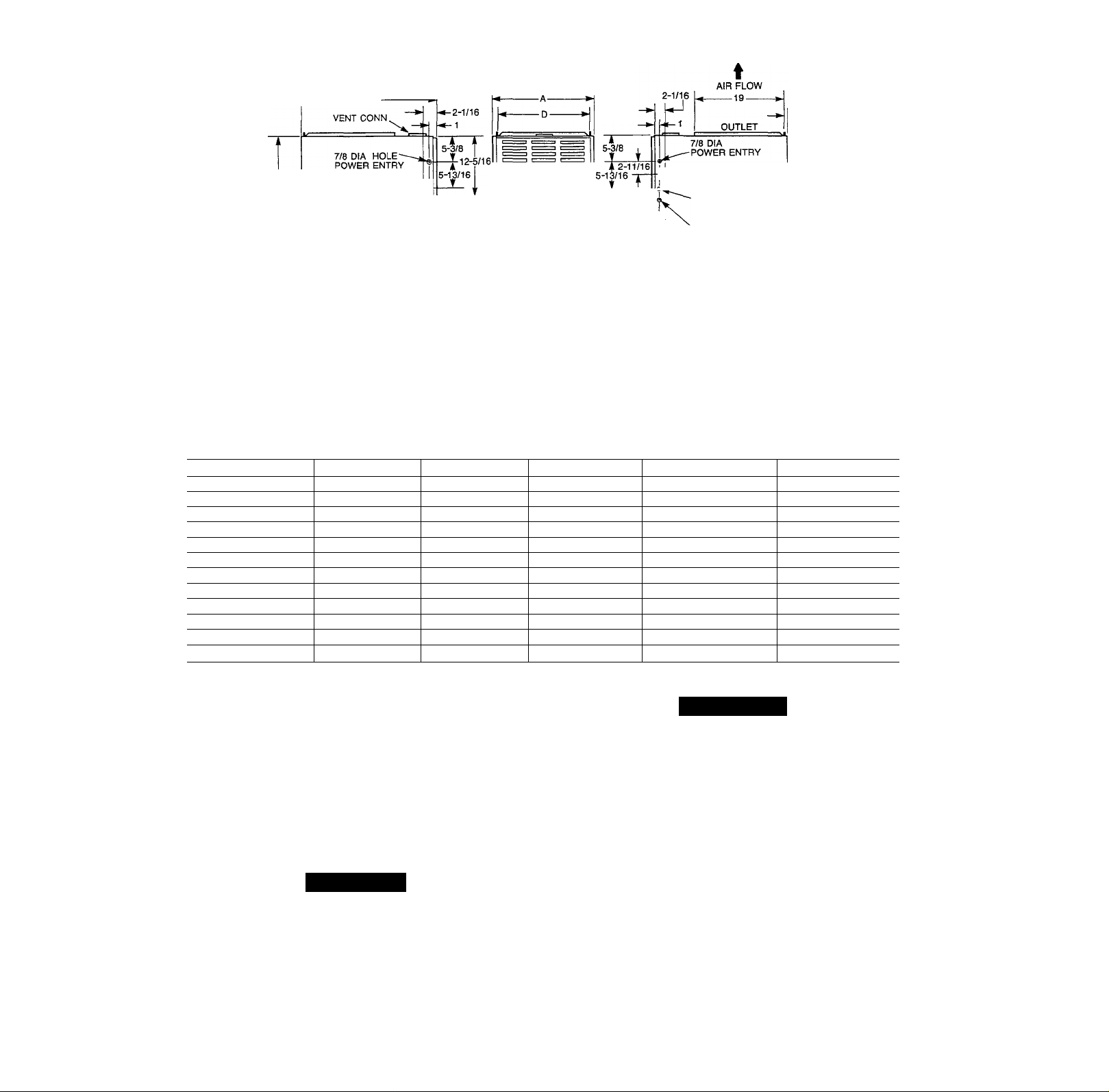
NOTE: 2 ADDITIONAL 7/8 DIA KNOCKOUTS
ARE LOCATED IN THE TOP PLATE
NOTE; AIR DELIVERY ABOVE 1800 CFM REQUIRES THAT BOTH SIDES OF FURNACE
BE USED, OR A COMBINATION OF 1 SIDE AND BOTTOM, OR BOTTOM ONLY FOR
RETURN AIR.
Table 2—Dimensions (In.)
UNIT SIZE
045-08
045-12 14-3/16
070-08
070-12
091-14 17-1/2 15-7/8 16
091-16
111-12 17-1/2 15-7/8 16
111-16
111-20
136-16
136-20
155-20
A
14-3/16 12-9/16
14-3/16 12-9/16 12-11/16
14-3/16 12-9/16 12-11/16
21 19-3/8 19-1/2 4
21
24-1/2 22-7/8 23
21
24-1/2 22-7/8 23
24-1/2 22-7/8 23 5
D E VENT CONN
12-9/16
19-3/8 19-1/2 4 166
19-3/8 19-1/2 5
Fig. 1—Dimensional Drawing
12-11/16
12-11/16
-11/16
SIDE INLET
INLET
-23-1/4-
4
4
4
4
4 150
4 160
4
5
14-1/2
1-3/4
SHIP. WT
A88367
122
124
132
134
154
184
178
194
204
Before installing the furnace, refer to the current edition of the
NFGC. Canadian installations must be installed in accordance with
NSCNGPIC and all authorities having jurisdiction. For further
information, the National Fuel Gas -Code is available from Na
tional Fire Protection Association Inc. Batterymarch Park, Quincy,
MA 02269, American Gas Association, 1515 Wilson Boulevard,
Arlington, VA 22209, or from Literature Distribution.
Installation must conform to the regulations of the serving gas
supplier and the local building, heating, and plumbing codes in
effect in the area in which the installation is made, or in the
absence of local codes with the requirements of the NFGC.
A CAUTION
Application of this furnace should be indoors with special
attention given to vent sizing and material, gas input rate, air
temperature rise, and unit sizing. Improper installation or
misapplication of the furnace can require excessive servicing
or cause premature component failure.
This furnace is designed for a minimum continuous return-air
temperature of 60°F db or an intermittent operation down to 55°F
db such as when used with a night setback thermostat. Return-air
temperature must not exceed a maximum of 85°F db.
WA
A WARNING
Improper installation, adjustment, alteration, service, mainte
nance, or use can cause carbon monoxide poisoning, explo
sion, fire, electrical shock, or other conditions which may
cause personal injury or property damage. Consult a qualified
installer, service agency, local gas supplier, or your distribu
tor or branch for information or assistance. The qualified
installer or agency must use only factory-authorized and
listed kits or accessories when modifying this product. A
failure to follow this warning can cause electrical shock, fire,
personal injury, or death.
For accessory installation details, refer to the applicable instruction
literature.
NOTE: Remove all shipping brackets and materials before
operating the furnace.

step 1—Location
GENERAL
A CAUTION
Do not install furnace in a corrosive or contaminated atmo
sphere. Make sure all combustion and circulating air require
ments are met, in addition to all local codes and ordinances.
A CAUTION
Do not use this furnace during construction when adhesives,
sealers, and/or new carpets are being installed. If the furnace
is required during construction, use clean outside air for
combustion and ventilation. Compounds of chlorine and
fluorine when burned with combustion air form acids which
will cause corrosion of the heat exchangers and metal vent
system. Some of these compounds are found in paneling and
dry wall adhesives, paints, thinners, masonry Ci-aning mate
rials, and many other solvents commonly used in ihe con
struction process.
This furnace must be installed so the electrical components are
protected from water.
Locate the furnace close to the chimney/vent and as near the center
of the air distribution system as possible. The furnace should be
installed as level as possible.
When a furnace is installed so that the supply ducts carry air to
areas outside the space containing the furnace, the return air must
also be handled by a duct(s) ’ sealed to the furnace casing and
terminating outside the space containing the furnace.
Provide ample space for servicing and cleaning. Always comply
with the minimum fire protection clearances shown on the unit
rating plate.
LOCATION RELATIVE TO COOLING EQUIPMENT - The
cooling coil must be installed parallel with or on the downstream
side of the furnace to avoid condensation in the heat exchangers.
When installed parallel with a furnace, dampers or other means
used to control the flow of air must prevent chilled air from
entering the unit. If the dampers are manually operated, they must
be equipped with means to prevent operation of either unit unless
the damper is in the full-heat or full-cool position.
HAZARDOUS LOCATIONS - When the furnace is installed in
a residential garage, it must be installed so that the burners and
ignition source are at least 18 in. above the floor. The furnace
should be protected from physical damage by vehicles. When a
furnace is installed in public garages, airplane hangars, or other
buildings having hazardous atmospheres, the unit must be installed
in accordance with the recommended good practice requirements
of the National Fite Protection Association, Inc.
Step 2—Air For Combustion and Ventilation
Provisions for adequate combustion and ventilation air must be
provided in accordance with Section 5.3, Air for Combustion and
Ventilation, of the NFGC or applicable provisions of the local
building codes.
Canadian installations must be installed in accordance with NSCNGPIC and all authorities having jurisdiction.
A CAUTION
Air for combustion must not be contaminated by halogen
compounds, which include fluoride, chloride, bromide, and
iodide. These elements are found in aerosol sprays, deter
gents, bleaches, cleaning solvents, salts, air fresheners, and
other household products.
All fuel-burning equipment must be supplied with air for combus
tion of the fuel. Sufficient air MUST be provided to ensure there
will not be a negative pressure in the equipment room or space. In
addition, a positive seal MUST be made between the furnace
cabinet and the return-air duct to prevent pulling air from the
burner area and draft safeguard opening.
A CAUTION
The operation of exhaust fans, kitchen ventilation fans,
clothes dryers, or fireplaces could create a NEGATIVE
PRESSURE CONDITION at the furnace. Make-up air MUST
BE PROVIDED for the ventilation devices, in addition to that
required by the furnace.
Combustion air requirements are determined by whether the
furnace is in an UNCONFINED or CONFINED space.
UNCONFINED SPACE — An unconfined space must have at
least 50 cu ft for each 1000 Btuh of input for all the appliances
(such as furnaces, clothes dryer, water heaters, etc.) in the space.
For Example:
58WAV FURNACE
INPUT BTUH
44,000 293
66,000 440
88,000
110,000 733
132,000 880
154,000 1026
If the unconfined space is of unusually tight construction, air for
combustion and ventilation MUST come from either the outdoors
or spaces freely communicating with the outdoors. Combustion
and ventilation openings must be sized the same as for a confined
space. A minimum opening with a total of at least 1 sq in. per 5000
Btuh of total input rating for all equipment must be provided.
Return air must not be taken from the room, unless an equal or
greater amount of air is supplied to the room.
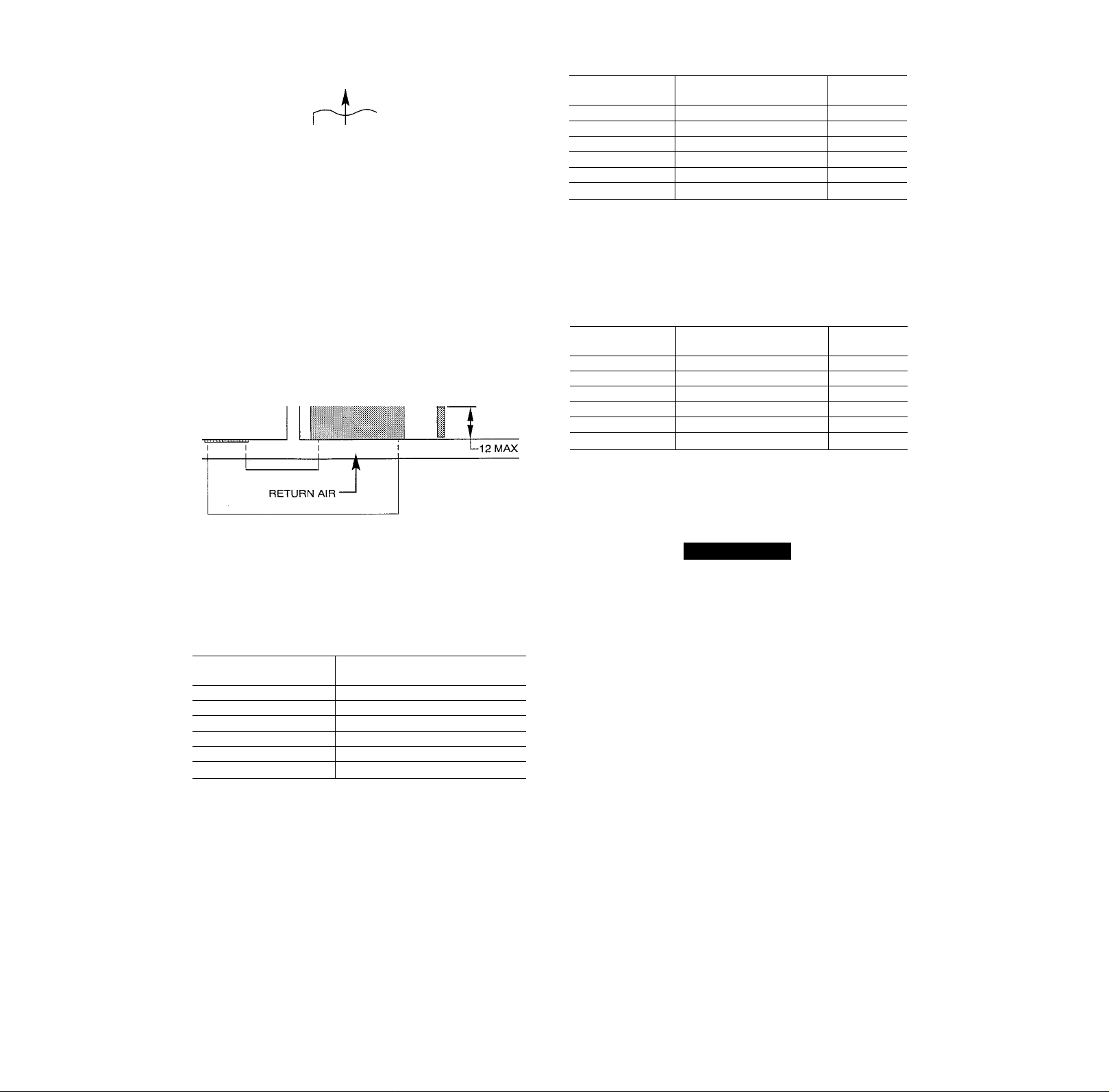
CONFINED SPACE — A confined space is one whose volume is
less than 50 cu ft per 1000 Btuh of the total output rating for all
appliances installed in that space. A confined space MUST have 2
permanent openings, 1 within 12 in. of the ceiling and the other
within 12 in. of the floor. (See Fig. 2.)
NOTE: In determining the free area of an opening, the blocking
effect of the louvers, grilles, and screens must be considered. If the
free area of a louver or grille design is unknown, it may be
assumed that wood louvers have a 20 percent free area and metal
louvers or grilles have a 60 percent free area. Screens, when used,
must not be smaller than 1/4-in. mesh. Louvers and grilles must be
constructed so they cannot be closed.
The size of the openings depends upon whether the air comes from
inside or outside of the structure.
1. All air from inside the structure:
Each opening MUST have at least 1 sq in. of free area per
1000 Btuh of the total input for all equipment within the
confined space, but not less than 100 sq in. per opening. (See
Fig. 2.)
MINIMUM SQ FT WITH
7-1/2 FT CEILING
587
SUPPLY
AIR
VENT THROUGH ROOF
(OATEGORY I) OR WALL
(CATEGORY III)
! I I
I I I
I I I
_12 MAX
1 1 SO IN.
Ш PER 1000
BTUH*
6 IN. MIN
(FRONT) +
1 SO IN.
PER 1000
BTUH*
INTERIOR
HEATED
SPACE
For Example:
58WAV FURNACE
INPUT BTUH
44,000 11.0
66,000
88,000 22.0
110,000 27.5
132,000 33.0
154,000
FREE AREA PER OPENING
(SQ IN.)
16.5
38.5
ROUND PIPE
(IN. DIA)
b. If combustion air is taken from the outdoors through
horizontal ducts, the openings and ducts MUST have at
least 1 sq in. of free area per 2000 Btuh of the total input
for all equipment within the confined space.
For Example:
58WAV FURNACE
INPUT BTUH
44,000 22.0
66,000 33.0
88,000 44.0
110,000
132,000 66.0 10
154,000 77.0
FREE AREA PER OPENING
(SQ IN.)
55.0 9
ROUND PIPE
(IN. DIA)
4
5
6
6
7
7
6
7
8
10
* Minimum opening size is 100 square in. with
minimum dimensions of 3 in.
+ Minimum of 3 in. when type-B vent is used.
A89012
Fig. 2—Air For Combustion and Ventilation
(Inside Air)
For Example:
58WAV FURNACE
INPUT BTUH
44,000
66,000
88,000
110,000
132,000
154,000
FREE AREA PER OPENING
(SQ IN.)
100
100
100
110
132
154
If the building is constructed unusually tight, a permanent opening
directly communicating with the outdoors should be provided.
This opening shall have a minimum free area of 1 sq in. per 5000
Btuh of total input rating for all equipment in the enclosure.
If the furnace is installed on a raised platform to provide a
return-air plenum, and return air is taken directly from the hallway
or space adjacent to the furnace, all air for combustion must come
from outdoors.
2. AJil air from outside the structure:
a. If combustion air is taken from outdoors through vertical
ducts, the openings and ducts MUST have at least 1 sq in.
of free area per 4000 Btuh of the total input for all
equipment within the confined space. (See Fig. 3.)
When ducts are used, they must be of the same cross-sectional area
as the free area of the openings to which they connect. The
minimum dimension of rectangular ducts must not be less than 3
in. (See Fig. 3.)
A WARNING
Do not install the furnace on its back; safety control operation
will be adversely affected. Never connect return-air ducts to
the back of the furnace. A failure to follow this warning can
cause a fire, personal injury, or death.
Step 3—Filter Arrangement
The factory-supplied filter(s) is shipped in the blower compart
ment. Determine location for the filter and move filter retaining
hardware, if necessary, before attaching the return-air duct. After
the return-air duct has been connected to the furnace, install the
filter(s) inside the furnace blower compartment. See Fig. 4 for side
return application and Fig. 5 for bottom return application.
A bottom closure panel is factory installed in the bottom of the
furnace. When bottom return inlet is desired, remove and discard
the enclosure panel.
Filter retaining brackets, supports, and retainers are factory as
sembled and shipped installed for side return application, with 1
set of all required hardware on each of the furnace. (See Fig. 4.)
For bottom return applications, remove the brackets (front and
back) and supports from each side. The back bracket(s) are
installed in the rear of the furnace casing (dimples are provided to
mark mounting screw locations).
The front bracket(s) are installed on the bottom front plate as
shown in Fig. 5, once the bottom enclosure has been removed.
Rotate filter supports 180° so filter will rest on support, and
reinstall. (Do not reinstall in 17-1/2 in. casing.) Install the filter
retaining rod (small U-shaped end) in the rear bracket, and the
front of the filter retainer rod as shown in Fig. 5. Two sets of
hardware are needed for furnaces in 24-1/2 in. casings using 2
filters for bottom return. All hardware is provided for filter
installation.
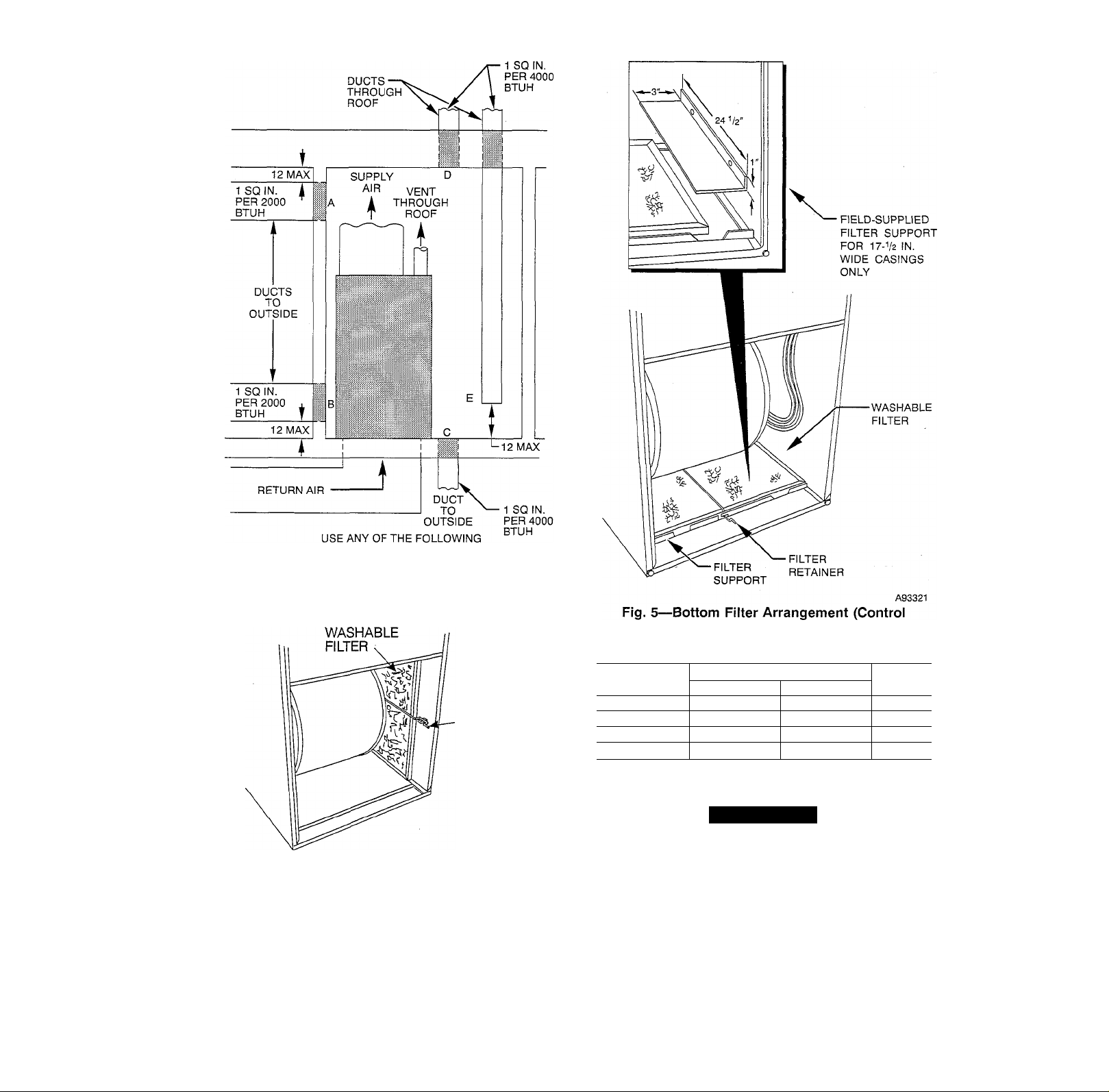
COMBINATIONS OF OPENINGS:
A&B C&D D&E
A89013
Fig. 3-
-Air For Combustion and Ventilation
(Outside Air)
•FILTER
RETAINER
SPRING
A93045
Fig. 4—Side Filter Arrangement (Control Removed
for Clarity)
NOTE: Furnaces with a 17-1/2 in. wide casing require an
additional procedure when locating the filter for bottom return-air
application. Field-fabricate a sheet metal filler strip 1 X 3 X 24-1/2
in. and install it along side of the filter as shown in Fig. 5. Drive
2 screws through the casing side and into the filler strip to secure
it in place. The filter is to rest on top of the filler strip when
installed.
Removed for Clarity)
Table 3—Filter Information (In.)
FURNACE
CASING WIDTH
14-3/16
17-1/2
21
24-1/2
* Filters can be field modified by cutting the frame as marked and folding to the
desired size. Alternate sizes can be ordered from your distributor or deaier.
t Factory provided virith the furnace.
(1) 16 X 25 X It
(1) 16 X 25 X It
(1) 16X25X 1 (1) 20 X 25 X ItCleanable
(2) 16 X 25 X 1t
FILTER SIZE*
Side Return
Bottom Return
(1) 14X25X1
(1) 16 X 25 X 1
(1) 24 X 25 X 1
FILTER
TYPE
Cleanable
Cleanable
Cleanable
A WARNING
Never operate unit without a filter or with filter access door
removed. Failure to follow this warning can cause fire,
personal injury, or death.
Step 4—Leveling Legs (If Required)
When the furnace is used with side inlet(s) and leveling legs are
required, refer to Fig. 6 and install field-supplied, corrosionresistant 5/16-in. machine bolts and nuts.
NOTE: The maximum length of the bolt should not exceed 1-1/2
in.
1. Lay furnace on its back. Locate and drill 5/16-in. diameter
hole in each bottom comer of furnace as shown in Fig. 6.
2. Install nut on bolt and install bolt and nut in hole. (Install flat
washer if desired.)
 Loading...