

Page 1
L010126H40 - 0404
UNIT AQUASNAP 30RA/RH
installation instructions
Istruzioni di installazione
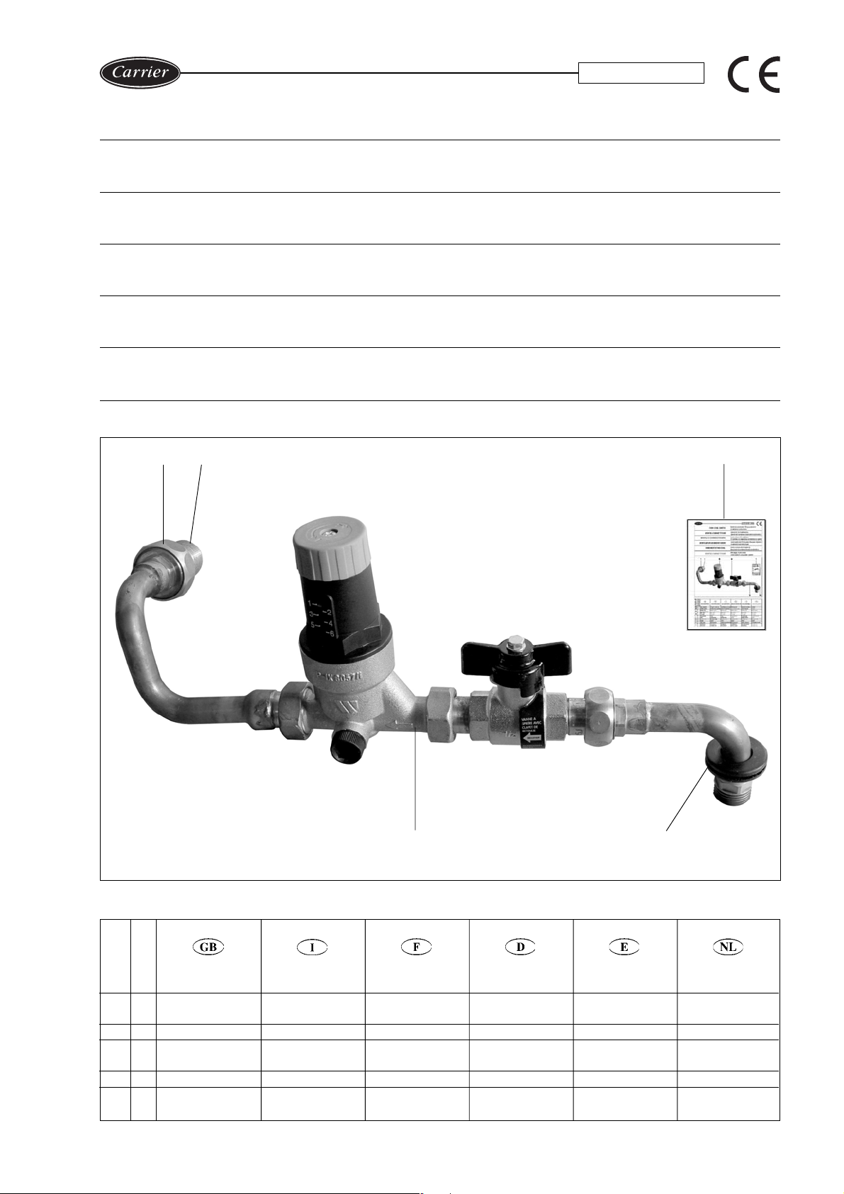
Optional automatic filling system kit
UNITÁ AQUASNAP 30RA/RH
Opzione kit sistema riempimento automatico
Instructions d’installation
UNITÉ AQUASNAP 30RA/RH
Kit système de remplissage automatique en option
Automatischer Füllsystem-Bausatz (Option)
GERÄT AQUASNAP 30RA/RH
Installationsanweisungen
Instrucciones de instalación
UNIDAD AQUASNAP 30RA/RH
Opcional kit sistema llenado automático
Montage- instructies
UNIT AQUASNAP 30RA/RH
DC
Automatisch vulsysteem (optie)
Ref. Q.ty
Rif. Q.tà
Ref. Q.té
Bez. Anz.
Ref. Can.
Rif. Q.tà
1 Pipe assembly
1 Rubber gasket
1
C 1 Nipple
D 1 Pipe union
DESCRIPTION
Installation
instruction
DESCRIZIONE
Gruppo tubazione
Guarnizione in gomma
Istruzioni di
installazione
Nipplo
Bocchettone
DESCRIPTION
Assemblage de
tuyauterie
Joint en caoutchouc
Consignes
d’installation
Téton
Raccord de
tuyauterie
BESCHREIBUNG
Rohrbausatz
Gummidichtungen
Installations-
anweisungen
Nippel
Rohranschluß
DESCRIPCIÓN
Conjunto de tubería
Junta de goma
Instrucciones de
installación
Racor
Racor de tubería
BESCHRIJVING
Leiding
Gummipakkingen
Installatieinstructies
Nippel
Leidingaansluiting
Page 2
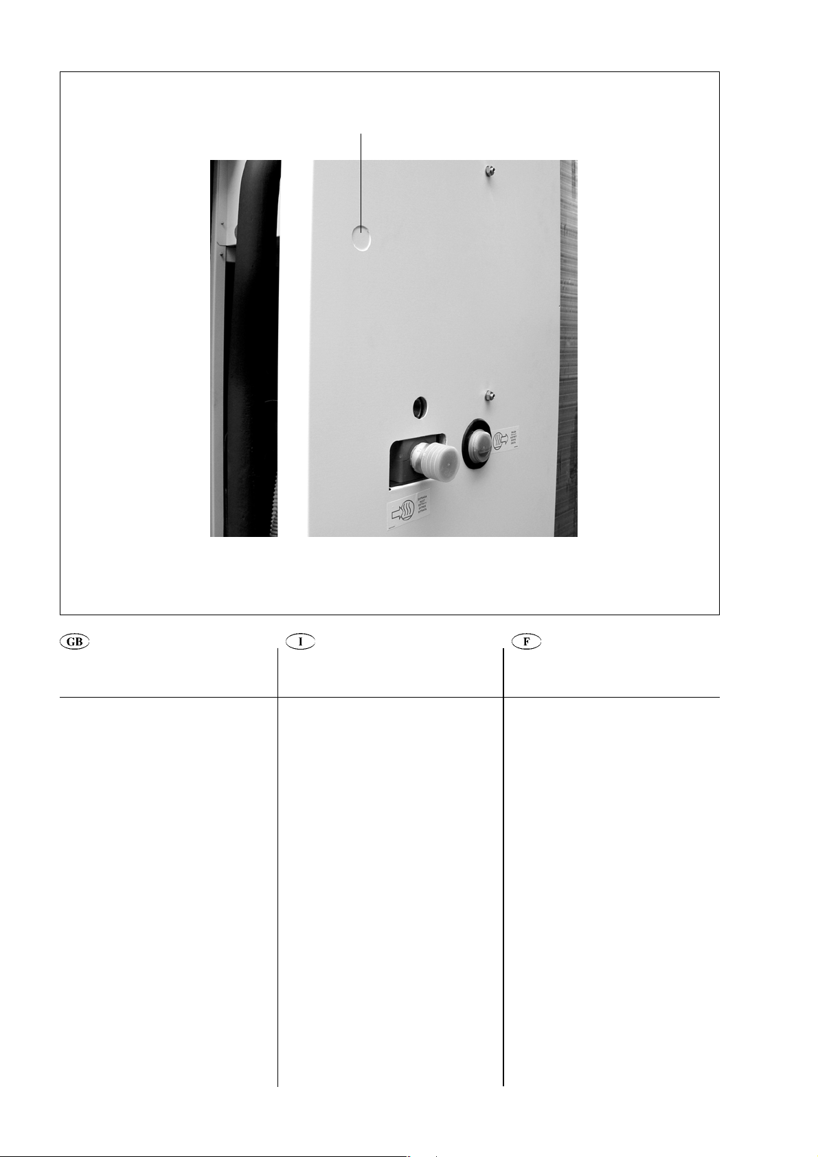
Fig./
Abb.
2
A
Assembly Montage
• Break pre-punched holes (A) on the
back panel to pass through the piping
(fig. 2).
• Remove the cap of Tee-joint (B).
Mount nipple (C) to Tee-joint (B) and
tighten it (fig. 3).
• Insert the pipe assembly into the
unit and pass the pipe end through
hole A.
• Mount the rubber gasket to the pipe
and pass it through hole A.
• Mount pipe union D to nipple C and
tighten (fig. 4).
IMPORTANT:
The water pressure-reducer must be set
at the maximum pressure of 300 kPa,
taking into consideration that safety valve
is set at 400 kPa.
Montaggio
• Rompere il foro pretranciato Aper
passaggio dal tubo sul pannello
posteriore (fig. 2).
• Smontare il tappo dal giunto a TEE (
Montare il nipplo (
(
B
) e serrare
C
) sul giunto a TEE
(fig. 3).
• Introdurre il gruppo tubazione
nell'unità e far passare attraverso il foro
A
l'estremità del tubo.
• Inserire la guarnizione di gomma
nella tubazione e posizionarla nel
foro
A
.
D
• Serrare il bocchettone
al nipplo
(fig. 4).
IMPORTANTE:
Il riduttore di pressione acqua deve
essere tarato alla pressione massima di
300 kPa, considerando che la taratura
della valvola di sicurezza è di 400 kPa.
B
).
C
• Percez les trous pré-perforés (A) sur le
panneau arrière pour faire passer à
travers la tuyauterie (fig. 2).
• Retirez le bouchon du Té (B).
Montez le téton (C) sur le Té (B) et
fixez-le (fig. 3).
• Insérer l’assemblage de tuyauterie
dans l’unité et faire passer l’extrémité
de la tuyauterie à travers le trou A.
• Introduire le joint en caoutchouc
dans la tuyauterie et la positionner dans
le trou A.
• Fixer le raccord de tuyauterie D au
téton C (fig. 4).
IMPORTANT:
Le réducteur de pression d’eau doit être
réglé à une pression maximum de
300 kPa, en tenant compte que la vanne
de sécurité est réglée à 400 kPa.
2
Page 3

Fig./
Abb.
Abb.
4
3
Fig./
A
Montage
• Das vorgestanzte Loch (A) am
Rückblech durchbrechen, um die
Rohrleitung durchzuführen (Abb. 2).
• Die Kappe der T-Verschraubung (
entfernen.
Nippel (
C
) an der T-Verschraubung (B)
anbringen und anziehen (Abb. 3).
• Die Rohrleitungsgruppe
einführen und das Rohrende durch das
Loch
A
führen.
• Die Gummidichtung
in die
Rohrleitung einführen und in dem Loch
A
positionieren.
D
• Rohranschluss
auf der Nippel
befestigen (Abb.4).
B
)
in das Gerät
C
B
C
D
Montaje
• Romper el orificio ciego prepunzonato
(A) para el paso del tubo en el panel
posterior (fig. 2).
• Desmontar la tapa de la unión en T (B).
Montar el racor (C) en la unión en T (B) y
apretar (fig. 3).
• Introducir el grupo tubería en la
unidad y hacer pasar la extremidad del
tubo a través del orificio A.
• Introducir la junta de goma en la
tubería y introducirla en el orificio A.
• Fijar la brida de unión D en el racor C
(fig. 4).
Montage
• Doorboor de voorgesneden opening in
het achterpaneel (
van de leiding (fig. 2).
•Verwijder de kap van de
vierwegaansluiting (
Plaats de nippel (
vierwegaansluiting (
vast (fig. 3).
• De leidingen
deze door de opening
het eind van de leiding.
• De gummipakking
leiding en deze plaatsen op de
opening
A
• De afdekkap D aanspannen aan de
buisnippel
A
) voor de doorgang
B
).
C
) op de
B
) en zet hem goed
inbrengen in de unit en
A
laten komen op
inbrengen op de
.
C
(fig. 4).
WICHTIG:
Der Wasser-Überdruckschutz muß auf
einen Maximalwert von 300 kPa
eingestellt werden, wobei das
Sicherheitsventil auf 400 kPa eingestellt
ist.
IMPORTANTE:
El reductor de presión del agua debe ser
tarado a la presión máxima de 300 kPa,
considerando que la taradura de la valvúla
de securidad es de 400 kPa.
3
BELANGRIJK:
Het waterdruk reduceerventiel moet
worden ingesteld op de max. druk van
300 kPa. Dit omdat het overstortventiel
standaard is ingesteld op 400 kPa.
Page 4

Carrier S.p.A. - Via R. Sanzio, 9 - 20058 Villasanta (MI) Italy - Tel. 039/3636.1
The manufacturer reserves the right to change any product specifications without notice.
La cura costante per il miglioramento del prodotto può comportare senza preavviso, cambiamenti o modifiche a quanto descritto.
Le fabricant se réserve le droit de modifier les spécifications du produit, sans préavis.
Änderungen im Zuge der technischen Weiterentwicklung vorbehalten.
El fabricante se reserva el derecho de cambiar las especificaciones de los productos sin previo aviso.
Wijzigingen voorbehouden.
April 2004. Printed in Italy
 Loading...