

Page 1
48PD05,06
48PG03---16
Gas Heating/Electric Cooling Rooftop Units
with PURONR (R --- 410A) Refrigerant
User’s Information Manual
NOTE TO INSTALLER:
This manual should be left with the equipment owner.
TABLE OF CONTENTS
SAFETY CONSIDERATIONS 1.........................
DETERMINE TYPE OF UNIT CONTROL 2...............
TO LIGHT UNIT 2....................................
Units With Electro--Mechanical Control 2.................
Units With ComfortLinkt Control 3.....................
TO SHUT UNIT OFF 6................................
Units With Electro--Mechanical Control 6.................
Units With ComfortLinkt Control 6.....................
MAINTAINING YOUR UNIT 9..........................
ROUTINE MAINTENANCE AND CARE FOR THE
EQUIPMENT OWNER 9...............................
Air Filter(s) 9.......................................
Alarm Status (Units with ComfortLink Control) 10..........
Integrated Gas Controller (IGC) 10.......................
Combustion Area and Vent System 10....................
Heat Exchanger 10...................................
Evaporator, Condenser and Combustion Fan Motors 10.......
Indoor Fan, Belt and Pulleys 10.........................
Indoor Fan Shaft Bearings (Sizes 03--14) 10................
Indoor Fan Shaft Bearings (Size 16) 10...................
Refrigerant Circuits 10................................
Evaporator and Condenser Coils 10......................
Condensate Drain 10.................................
Compressors 11.....................................
Condenser Fan 11....................................
Electrical Controls and Wiring 11........................
Unit Panels 11......................................
REGULAR DEALER MAINTENANCE 11................
BEFORE YOU CALL FOR SERVICE CHECK FOR
SEVERAL EASILY SOLVED PROBLEMS 11..............
If insufficient heating or cooling is suspected 11.............
If your unit is not operating at all 11......................
IN CASE OF TROUBLE 11.............................
SAFETY CONSIDERATIONS
Improper installation, adjustment, alteration, service, maintenance,
or use can cause fire, electrical shock, or other conditions which
may cause personal injury or property damage. Consult a qualified
installer, service agency or your distributor or branch for
information or assistance. The qualified installer or agency must
use factory--authorized kits or accessories when modifying this
product. Refer to the individual instructions packaged with the kits
or accessories when installing.
Follow all safety codes. Wear safety glasses and work gloves.
Have fire extinguishers available.
Recognize safety information. This is the safety--alert symbol
When you see this symbol on the furnace and in instructions or
manuals, be alert to the potential for personal injury.
Understand the signal words DANGER, WARNING, and
CAUTION. These words are used with the safety--alert symbol.
DANGER identifies the most serious hazards which will result in
severe personal injury or death. WARNING signifies a hazard
which could result in personal injury or death. CAUTION is used
to identify unsafe practices which ma y result in minor personal
injury or product and property damage. NOTE is used to highlight
suggestions which will result in enhanced installation, reliability, or
operation.
!
WARNING
FIRE, EXPLOSION HAZARD
Failure to follow this warning could result in personal
injury, death and/or property damage.
Do not store or use gasoline or other flammable vapors
and liquids in the vicinity of this or any other appliance.
What to do if you smell gas:
1. DO NOT try to light any appliance.
2. DO NOT touch any electrical switch or use any
phone in your building.
3. Leave the building immediately.
3. IMMEDIATELY call your gas supplier from a
neighbor’s phone. Follow the gas supplier’s
instructions.
4. If you cannot reach your gas supplier, call the fire
department.
Installation and service must be performed by a
qualified installer, service agency or the gas supplier.
.
Page 2
Always keep the unit’s area clear of combustible materials. Do not
obstruct the air openings to the unit. Air is required for
combustion and ventilation proper operation. Follow the
instruction provided in this book for lighting and shutting down
the unit. Should the gas supply fail to shut off or if overheating
occurs, shut off the gas valve to the unit before shutting off the
electrical supply. The following inspections must be completed
post unit installation. The detailed routine maintenance inspections
are in the Maintaining Your Unit section.
Post Unit Installation Inspection:
1. All flue and vent connections are clear and free of
obstructions, are leak free, and not damaged.
2. Duct connections are leak free and physically sound.
3. The unit base support is free of cracks, gaps, etc.
4. There are no signs of furnace deterioration.
5. Burners are aligned correctly.
6. Follow routine maintenance inspection.
!
WARNING
FIRE, EXPLOSION HAZARD
48PD, 48PG
Failure to follow this warning could result in personal injury
and/or death.
Improper installation, adjustment, alteration, service or
maintenance can cause injury or property damage. Refer to
this manual. For assistance or additional information, consult
a qualified installer, service agency or the gas supplier.
!
WARNING
FIRE, EXPLOSION HAZARD
Failure to follow this warning could result in personal injury,
death and/or property damage.
Burners will light automatically. Do not attempt to light by
hand.
DETERMINE TYPE OF UNIT CONTROL
The procedures used to light or shut off the unit depend on the type
of unit control. This section will help determine the control type of
the unit.
Electro--Mechanical Control
These units may be controlled directly by a thermostat, or
indirectly by a third--party control that connects to the thermostat
inputs. For direct thermostat control, use the Electro--Mechanical
Control procedures in this book. For units with third--party
controls connected to the thermostat inputs, refer to the third--party
control instructions for procedures to ensure complete unit shut off.
ComfortLinkt Control
These units have a factoryinstalled Carrier ComfortLink control. A
Scrolling Marquee display is located on the front of the unit control
box behind the control box and compressor access door. These
units may be controlled directly by a thermostat, directly by a space
temperature sensor, or indirectly through other Carrier Comfort
Networkr (CCN) communication devices. To ensure complete unit
shut off, use the ComfortLink Control procedures in this book.
TO LIGHT UNIT
(UNITS WITH ELECTRO--MECHANICAL
CONTROL)
!
FIRE, EXPLOSION HAZARD
Failure to follow this warning could result in personal injury
or death.
1. Do not turn off the electrical power to unit without first
turning off the gas supply and applying lockout tags.
2. Before attempting to start the gas heating section, familiarize
yourself with all the procedures that must be followed.
3. Never attempt to manually light the burners on the unit with
a match, lighter, or any other flame. If the electric sparking
device fails to light the burners, refer to the shutdown
procedures, then call your dealer as soon as possible.
DANGER
Your combination heating/cooling unit is equipped with direct
spark ignition and induced draft power combustion blower.
!
WARNING
FIRE, EXPLOSION HAZARD
Failure to follow this warning could result in personal injury,
death and/or property damage.
Burners will light automatically. Do not attempt to light by
hand.
!
WARNING
ELECTRICAL OPERATION HAZARD
Failure to follow this warning could result in personal injury,
death and/or property damage.
Do not use this unit if any part has been under water. A
flood--damaged unit is extremely dangerous. Attempts to use
the unit can result in fire or explosion. A qualified service
agency should be contacted to inspect the unit and replace any
parts that have been wet or the unit, if deemed necessary.
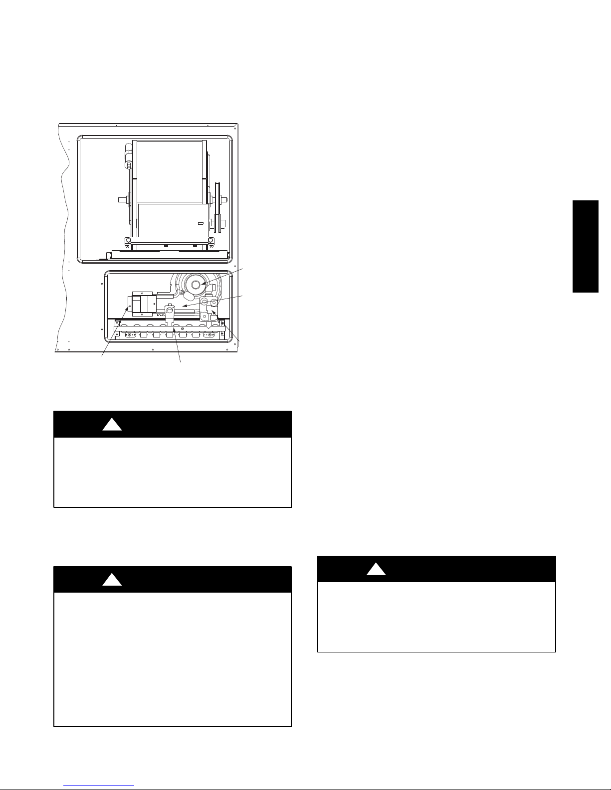
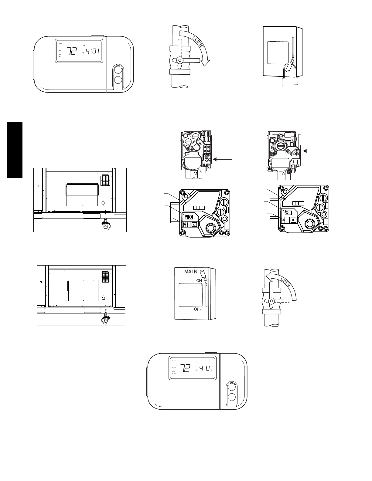
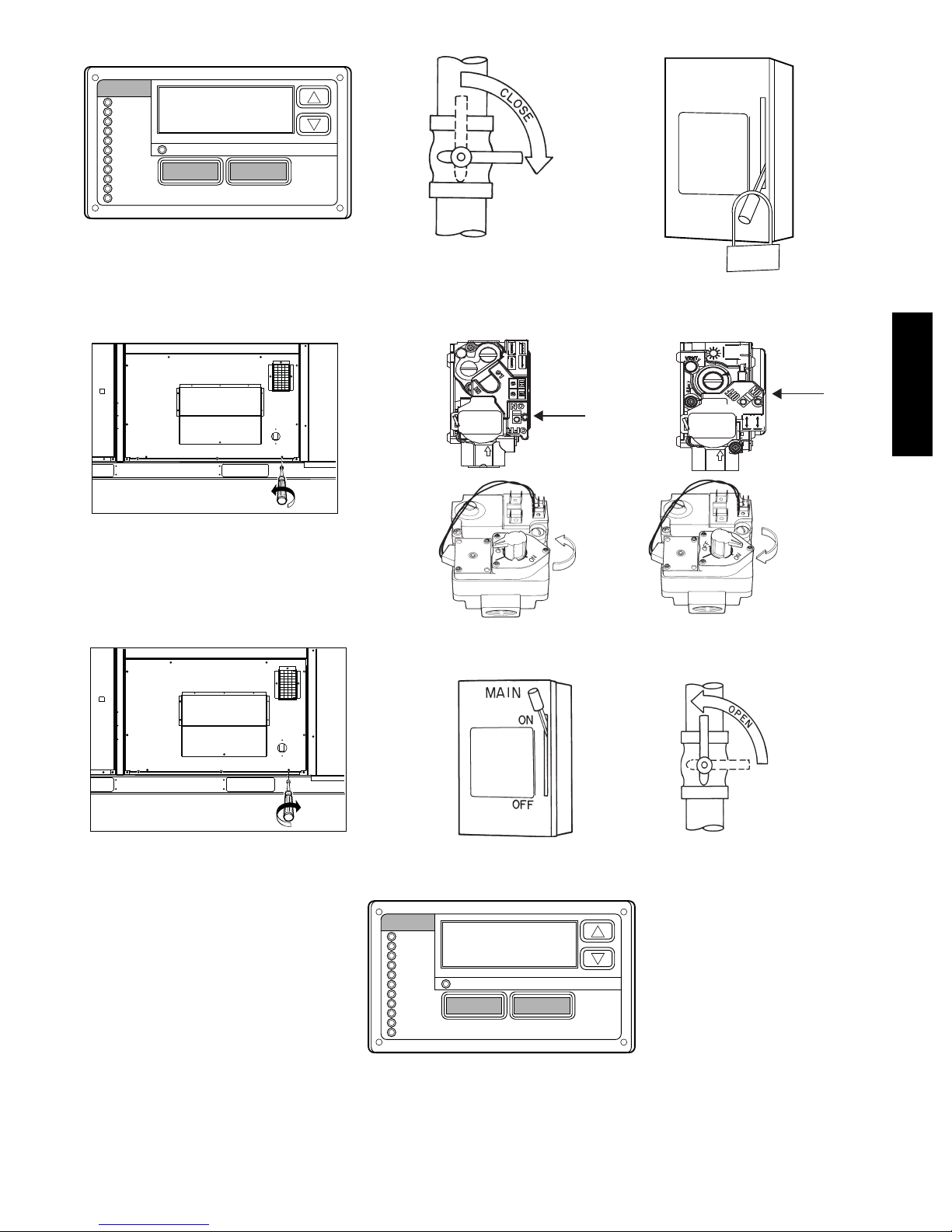
See Fig. 1. for location of gas valve. Refer to Fig. 2 while
proceeding with the following steps:
Step 1 — Set room thermostat to the lowest temperature setting
andsetSYSTEMswitchtoOFFposition.
Step 2 — Close the shutoff valve on the gas supply piping.
Step 3 — Turn off the electrical supply to the unit and install
lockout tag.
Step 4 — Open the heat section access panel.
Step 5 — Move ON/OFF switch on the internal main gas valve
to the OFF position an
Step 6 — Move ON/OFF switch on internal main gas valve to
ON position.
Step 7 — Close the heat section access panel.
Step 8 — Remove lockout tag and turn on the electrical supply
to unit.
Step 9 — Open the shutoff valve on the external gas supply
piping.
2
Page 3
Step 10 — Set room thermostat selector slightly above room
temperature and set system switch to HEAT position to start the
unit. The induced--draft combustion air fan will start. Main burners
light within 30 seconds. Indoor blower will start within 60 to 90
seconds of main gas ignition.
Step 11 — Set the temperature selector on room thermostat to
desired setting.
INDUCED
DRAFT
MOTOR
COMBUSTION
FAN HOUSING
MAIN GAS
VALVE
HEAT EXCHANGER
SECTION
Fig. 1 -- Typical Gas Heating Section
!
FIRE, EXPLOSION HAZARD
Failure to follow this warning could result in personal injury,
death, and/or property damage.
If the main burners fail to light, or the blower fails to come on,
shut down gas heating section and call your dealer for service.
MAIN BURNER SECTION
C06258
WARNING
TO LIGHT UNIT
(UNITS WITH COMFORTLINKt
CONTROL)
!
FIRE, EXPLOSION HAZARD
Failure to follow this warning could result in personal injury,
death, and/or property damage.
1. Do not turn off the electrical power to unit without first
turning off the gas supply and applying lockout tags.
2. Before attempting to start the gas heating section, familiarize
yourself with all the procedures that must be followed.
3. Never attempt to manually light the burners on the unit with
a match, lighter, or any other flame. If the electric sparking
device fails to light the burners, refer to the shutdown
procedures, then call your dealer as soon as possible.
DANGER
See Fig. 1. for location of gas valve. Refer to Fig. 3 while
proceeding with the following steps:
Step 1 — Turn off the unit by using the Scrolling Marquee to
put the unit into Service Test mode. The Scrolling Marquee is
located on the front of the unit control box behind the control box
and compressor access door. Thermostat inputs and remote
network commands are ignored when Service Test mode is ON.
NOTE: A password may be required to change Service Test
values, depending on previous settings configured in the unit.
Default password is “1111.”
a. Press the ESCAPE key until a blank screen is shown.
b. Use the arrow keys to scroll the red LED on the display
to the “Service Test” position and press ENTER.
c. The control will display the Field Service Test Mode
(TEST) setting. Press ENTER once to select the TEST
setting for configuration. Press ENTER again for “OFF”
to begin flashing.
d. Use the arrow keys to change the configuration from
“OFF” to “ON,” then press ENTER to save the setting.
Step 2 — Close the shutoff valve on the gas supply piping.
Step 3 — Turn off the electrical supply to the unit and install
lockout tag.
Step 4 — Open the heat section access panel.
Step 5 — Move ON/OFF switch on the internal gas valve to the
OFF position and wait 5 minutes.
Step 6 — Move ON/OFF switch on internal gas valve to ON
position.
Step 7 — Close the heat section access panel.
Step 8 — Remove lockout tag and turn on the electrical supply
to unit.
NOTE: Normal operation will automatically begin. Service Test
mode will automatically end (exit) after a recycle of power.
Step 9 — Open the shutoff valve on the external gas supply
piping.
Step 10 — To test the operation of the gas section, the HEAT
submenu of Service Test may be used. See the Controls, Start--Up,
Operation, Service, and Troubleshooting Instructions for more
details on use of Service Test.
Step 11 — For normal operation, make sure that the set points
are at the normal heat set points.
!
WARNING
FIRE, EXPLOSION HAZARD
Failure to follow this warning could result in personal injury,
death, and/or property damage.
If the main burners fail to light, or the blower fails to come on,
shut down gas heating section and call your dealer for service.
48PD, 48PG
3
Page 4
MAIN
f
OFF
ON
UT
-O
K
C
LO
G
A
T
48PD, 48PG
STEP 1
STEP 4
CONTROL I.D.
LABEL
SWITCH (SHIPPED IN
“ON” POSITION)
1/4˝ X .032˝ MALE SPADE
TERMINALS (2) COMMON
STEP 2
Two-Stage
RTU gas valve
OFF
ON
STEP 5
On/Off
Switch
SWITCH (SHIPPED IN
“ON” POSITION)
1/4˝ X .032˝ MALE SPADE
TERMINALS (2) COMMON
CONTROL I.D.
LABEL
STEP 3
Single-Stage
RTU gas valve
OFF
ON
STEP 6
On/Of
Switch
STEP 7
Fig. 2 -- To Light Unit (Units with Electro--Mechanical Control)
STEP 8
STEP 10
4
STEP 9
C08541
Page 5
MODE
f
Run Status
Service Test
Temperature
Pressures
Setpoints
Inputs
Outputs
Configuration
Time Clock
Operating Modes
Alarms
Alarm Status
ESCAPE
MAIN
ON
ENTER
OFF
STEP 1
STEP 4
STEP 2
Two-Stage
RTU gas valve
STEP 5
On/Off
Switch
O
L
STEP 3
Single-Stage
RTU gas valve
STEP 6
T
U
-O
K
C
G
TA
On/Of
Switch
48PD, 48PG
STEP 7
Fig. 3 -- To Light Unit (Units with ComfortLinkt Control)
MODE
Run Status
Service Test
Temperature
Pressures
Setpoints
Inputs
Outputs
Configuration
Time Clock
Operating Modes
Alarms
STEP 8
Alarm Status
ESCAPE
STEP 10
STEP 9
ENTER
C08542
5
Page 6
TO SHUT UNIT OFF
(UNITS WITH ELECTRO--MECHANICAL
CONTROL)
TO SHUT UNIT OFF
(UNITS WITH COMFORTLINK
CONTROL)
t
!
WARNING
FIRE HAZARD
Failure to follow this warning could result in personal injury,
death, and/or property damage.
Do not turn off the electrical power to unit without first turning
off the gas supply. Should the gas supply fail to shut off or if
overheating occurs, shut off the gas valve to the unit before
shutting off the electrical supply. Make sure to apply lockout
tags.
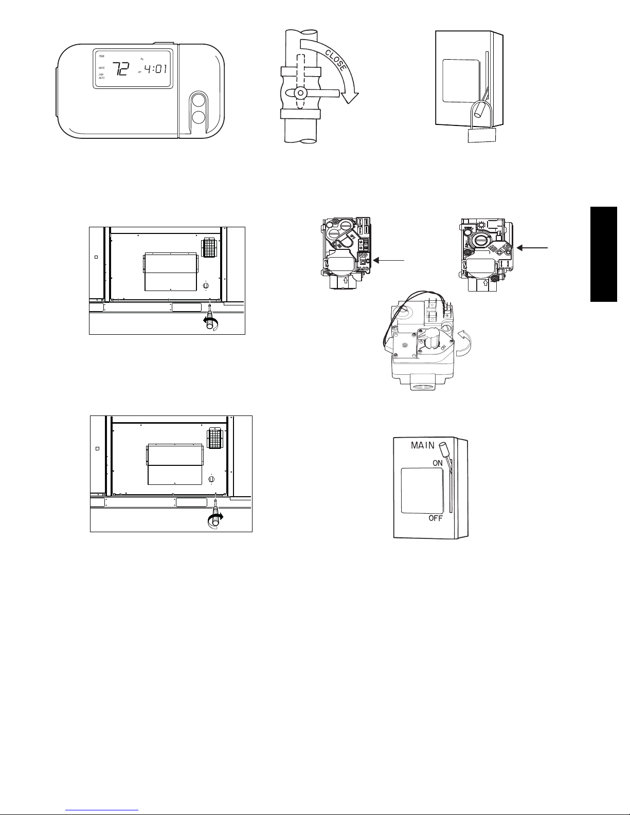
See Fig. 1. for location of gas valve. Refer to Fig. 4 while
proceeding with the following steps:
Step 1 — Set room thermostat to lowest temperature setting and
set SYSTEM switch to OFF position.
Step 2 — Close the shutoff valve on the external gas supply
48PD, 48PG
piping.
Step 3 — Turn off the electrical power supply to the unit and
install lockout tag.
Step 4 — Open the heat section access panel.
Step 5 — Move ON/OFF switch on the internal gas valve to the
OFF position.
Step 6 — Close the heat section access panel.
Step 7 — If unit is being shut down because of a malfunction,
call your dealer as soon as possible.
If unit is being shut down because the heating season has ended,
restore electrical power to the unit to ensure operation of the
cooling system during the cooling season.
!
WARNING
FIRE HAZARD
Failure to follow this warning could result in personal injury,
death, and/or property damage.
Do not turn off the electrical power to unit without first turning
off the gas supply. Should the gas supply fail to shut off or if
overheating occurs, shut off the gas valve to the unit before
shutting off the electrical supply. Make sure to apply lockout
tags.
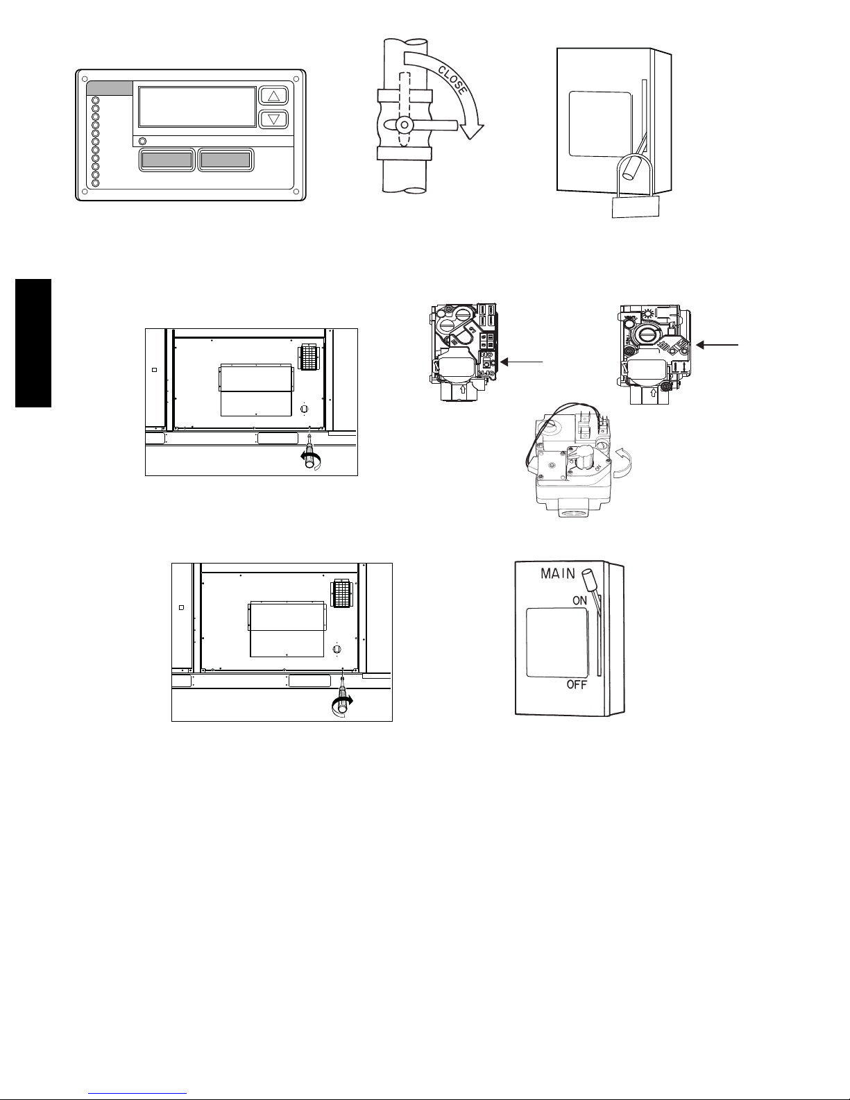
See Fig. 1. for location of gas valve. Refer to Fig. 5 while
proceeding with the following steps:
Step 1 — Turn off the unit operation by using the Scrolling
Marquee to put the unit into Service Test mode. The Scrolling
Marquee is located on the front of the unit control box behind the
control box and compressor access door. (See Fig. 6.) Thermostat
inputs and remote network commands are ignored when Service
Test mode is ON.
NOTE: A password may be required to change Service Test
values, depending on previous settings configured in the unit.
Default password is “1111.”
a. Press the ESCAPE key until a blank screen is shown.
b. Use the arrow keys to scroll the red LED on the display
to the “Service Test” position and press ENTER.
c. The control will display the Field Service Test Mode
(TEST) setting. Press ENTER once to select the TEST
setting for configuration. Press ENTER again for “OFF”
to begin flashing.
d. Use the arrow keys to change the configuration from
“OFF” to “ON,” then press ENTER to save the setting.
Step 2 — Close the shutoff valve on the external gas supply
piping.
Step 3 — Turn off the electrical power supply to the unit and
install lockout tag.
Step 4 — Open the heat section access panel.
Step 5 — Move ON/OFF switch on the internal gas valve to the
OFF position.
Step 6 — Close the heat section access panel.
Step 7 — If unit is being shut down because of a malfunction,
call your dealer as soon as possible. If unit is being shut down
because the heating season has ended, restore electrical power to
the unit to ensure operation of the cooling system during the
cooling season.
6
Page 7
MAIN
OFF
LO
ON
T
U
-O
K
C
G
TA
STEP 1
STEP 4
STEP 2
Two-Stage
RTU gas valve
On/Off
Switch
STEP 5
STEP 3
Single-Stage
RTU gas valve
On/Off
Switch
48PD, 48PG
STEP 6
Fig. 4 -- To Shut Unit Off (Units with Electro--Mechanical Control)
STEP 7
C08543
7
Page 8
MAIN
48PD, 48PG
MODE
Run Status
Service Test
Temperature
Pressures
Setpoints
Inputs
Outputs
Configuration
Time Clock
Operating Modes
Alarms
Alarm Status
ESCAPE
STEP 1
ENTER
STEP 2
Two-Stage
RTU gas valve
On/Off
Switch
OFF
LOC
STEP 3
ON
UT
-O
K
G
TA
Single-Stage
RTU gas valve
On/Off
Switch
STEP 4
STEP 6
Fig. 5 -- To Shut Unit Off (Units with ComfortLinkt Control)
STEP 5
STEP 7
C08544
8
Page 9
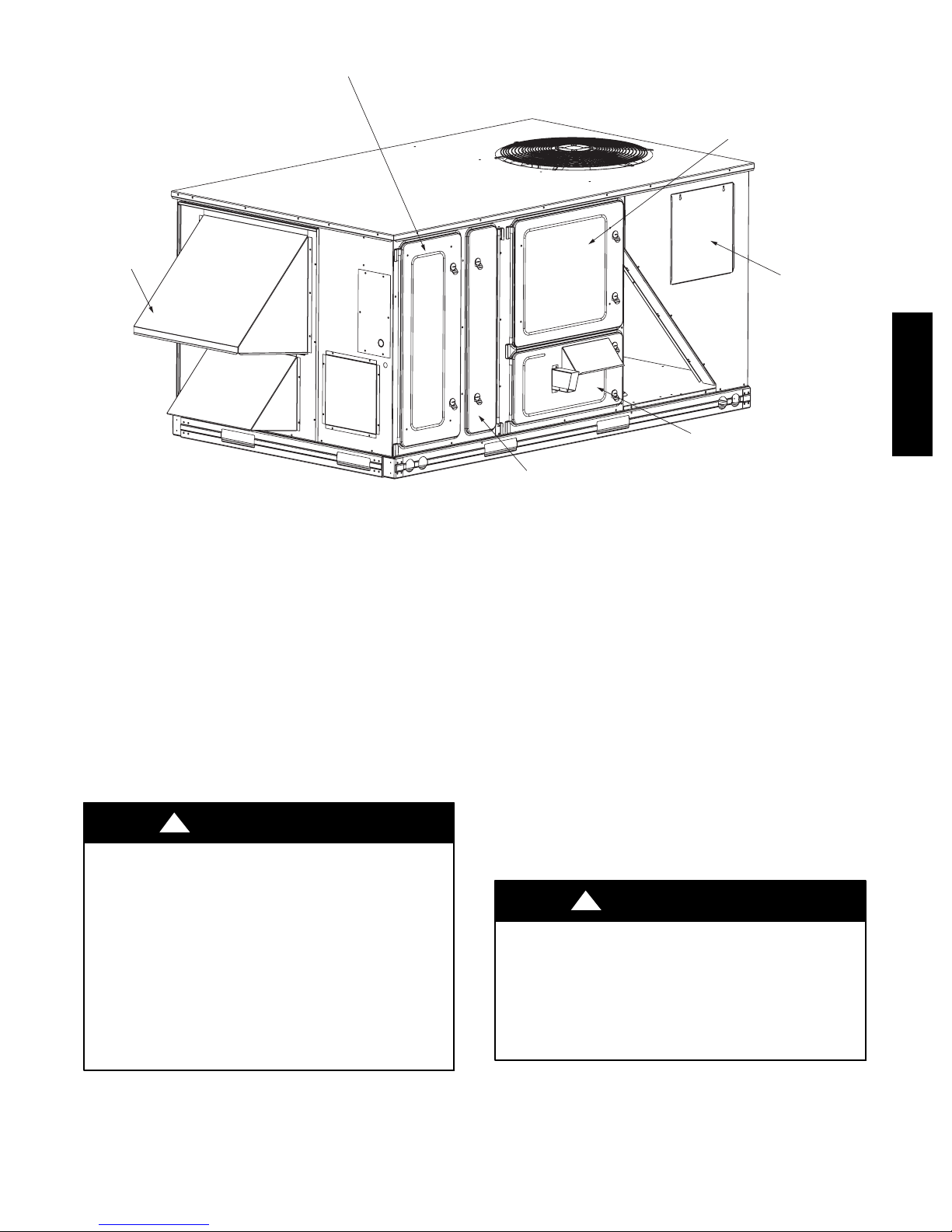
OUTDOOR AIR
SCREEN
CONTROL BOX
AND COMPRESSOR
ACCESS DOOR
FILTER ACCESS DOOR
INDOOR MOTOR
ACCESS DOOR
GAS SECTION
ACCESS DOOR
CONDENSER COIL
ACCESS DOOR
48PD, 48PG
Fig. 6 -- Panel and Filter Locations (48PG03--07 Shown)
MAINT AINING YOUR UNIT
All maintenance should be handled by skilled, experienced
personnel. Your dealer can help you establish a standard procedure.
For your safety, keep the area around the unit clear and free of
combustible materials, gasoline and other flammable liquids and
vapors.
To assure proper functioning of the unit, flow of combustion and
ventilating air must not be obstructed from reaching the unit.
Clearance of at least 6 ft on all sides is required.
ROUTINE MAINTENANCE AND CARE
FOR THE EQUIPMENT OWNER
Before proceeding with those things you might want to maintain
yourself, please carefully consider the following:
!
WARNING
FIRE, EXPLOSION HAZARD
Failure to follow this warning could result in personal injury,
death, and/or property damage.
1.Turn off gas supply and electrical power to your unit before
servicing or performing maintenance.
2. Do not turn off electrical power to this unit without first
turning off gas supply and applying lockout tags.
3. When removing access doors or performing maintenance
functions inside your unit, be aware of sharp sheet metal
parts and screws. Although special care has been taken to
reduce sharp edges to a minimum, be extremely careful
when handling parts or reaching into the unit.
C08545
Air Filter(s)
Air filters should be checked at least every 3 or 4 weeks and
changed or cleaned whenever they become dirty. Table 1 indicates
the correct filter size for your unit. Open the filter access panel to
replace or inspect the filters. All units have filter tracks into which
the filters slide. Remove the filters by pulling the filter slide
outward from the track. See Fig. 6 for filter access panel location.
Note the direction of flow arrows on the filter frame.
If you have difficulty in locating your air filter in the return--air
duct system, or if you have questions concerning proper filter
maintenance, contact your dealer for instructions. When replacing
your unit filters, always use the correct size and quantity as shown
in Table 1. Filter tracks are field convertible for 2 or 4--in. thick
filters. Verify airflow and duct static values, and related motor
sizing and belt drive adjustment, if filter type or efficiency rating is
changed from the original installation.
Units with outdoor air capability have cleanable screens for the
outdoor air. These screens should be checked annually and cleaned
as necessary.
!
WARNING
FIRE AND EQUIPMENT DAMAGE HAZARD
Failure to follow this warning could result in personal injury,
death, and/or property damage.
Never operate unit without filters in place. Damage to blower
motor and/or compressors could result. An accumulation of
dust and lint on internal parts of your unit can cause loss of
efficiency and in some cases, fire.
9
Page 10
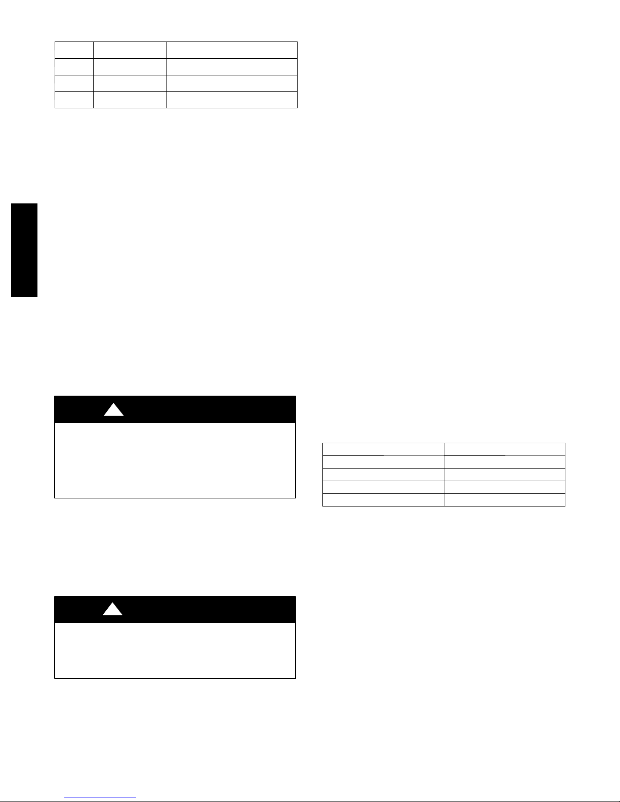
Table 1 – Indoor Air Filter Data
UNIT
SIZE
03---07
08---14
FILTER QUANTITY FILTER SIZE
4
4
16
8
(406.4 x 508 x [50.8 or 101.6]) mm
(508 x 635 x [50.8 or 101.6]) mm
(508 x 508 x [50.8 or 101.6]) mm
16x20x(2or4)in
20x25x(2or4)in
20x20x(2or4)in
Alarm Status
(Units with ComfortLinkt Controls)
The Scrolling Marquee display incorporates an Alarm Status LED
that turns on to indicate an active alarm or alert. These alarms and
alerts are in addition to those that are indicated by the Integrated
Gas Control (IGC). The ComfortLink control active alarm codes
and alarm history can be viewed with the Scrolling Marquee or
other Carrier Comfort Networkr (CCN) devices. Alarms may also
be configured to broadcast automatically on CCN. If the unit will
not operate and the Alarm Status LED is on, contact the local
dealer and request service.
Integrated Gas Controller (IGC)
The IGC board incorporates an LED that emits a flashing light to
48PD, 48PG
indicate an alarm code. If the furnace section will not operate and
the LED is flashing a code (1 to 9 flashes in succession), contact
your dealer and request service.
NOTE: Make note of the flash code before powering off the unit.
The alarm codes clear after power cycle.
Combustion Air and Vent System
The combustion area and vent system should be visually inspected
before each heating season. The normal accumulation of dirt, soot,
rust, and scale can result in loss of efficiency and improper
performance if allowed to build up.
!
WARNING
FIRE HAZARD
Failure to follow this warning could result in personal injury,
death, and/or property damage.
If your unit makes and especially loud noise when the main
burners are ignited, shut down the heating section and call
your dealer.
See Fig. 1 and proceed as follows to inspect the combustion area
and power--venting system of your unit.
7. Turn off electrical power (install disconnect tag) and gas
supply to your unit (follow Shut-- Off Steps 1--3).
8. Open burner compartment access panel.
9. Using a flashlight, carefully inspect the burner areas for dirt,
soot, or scale.
!
CAUTION
EQUIPMENT DAMAGE HAZARD
Failure to follow this caution may result in damage to unit.
If dirt, soot, rust or scale accumulations are found, call your
dealer and do not operate your heating section.
10. When you have completed your inspection, follow the
start-- up procedures in this manual to restore your unit to
operation.
11. Observe unit heating operation, and watch the burner flame
with the access panel removed to see if it is bright blue. If
you observe a suspected malfunction, or that the burner
flames are not bright blue, call your dealer. Some yellow
flame may be present due to the panel being removed.
12. Close burner compartment access panel.
Heat Exchanger
To ensure dependable and efficient heating operation, the heat
exchanger should be checked by a qualified maintenance person
before each heating season, and cleaned when necessary. This
checkout should not be attempted by anyone not having the
required expertise and equipment to do the job properly. Checking
and/or cleaning the heat exchanger involves removing the gas
controls assembly and the flue collector box cover and, when
completed, reinstalling the gas controls assembly for proper
operation. The flue collector box cover must be reinstalled with
“red” RTV correctly so that a proper seal is maintained. Contact
your dealer for the required periodic maintenance.
Evaporator, Condenser and Combustion Fan
Motors
The indoor fan, outdoor fan, and combustion fan motors have
permanently sealed bearings, so no field lubrication is necessary.
Indoor Fan, Belt and Pulleys
Check quarterly the condition of the fan wheel(s), pulleys, fan belt
and the belt tension. If there is any loose part or belt wear, contact
your dealer and request service.
Indoor Fan Shaft Bearings (Sizes 03--14)
The indoor fan has permanently sealed bearings, so no field
lubrication is necessary.
Indoor Fan Shaft Bearings (Size 16)
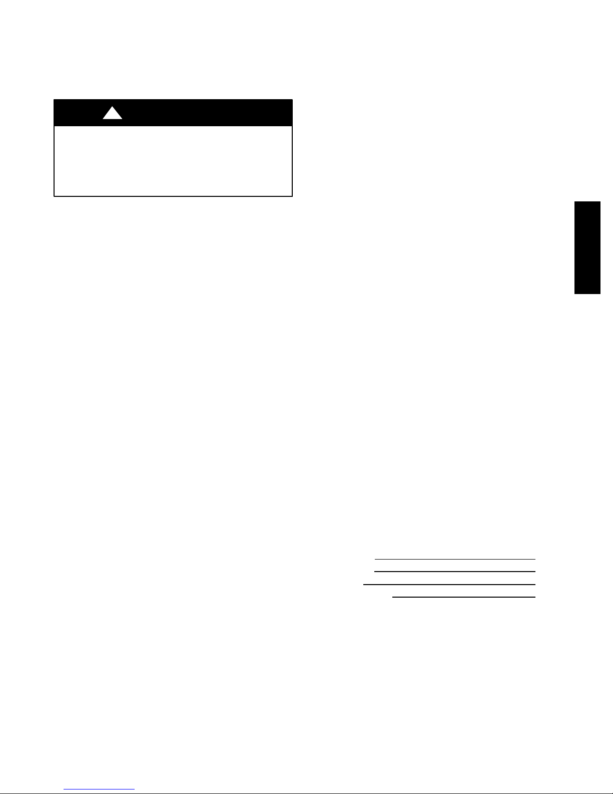
Lubricate bearings at least every 6 months with suitable bearing
grease. Typical lubricants are given below:
MANUFACTURER LUBR ICANT
Texa co R e g a l A F B --- 2 *
Mobil Mobilplex EP No. 1
Sunoco Prestige 42
Texa co Multifak 2
* Preferred lubricant because it contains rust and oxidation inhibitors.
Refrigerant Circuits
The refrigerant circuits are difficult to check for leaks without the
proper equipment; therefore, if inadequate cooling is suspected,
contact your dealer for service.
Evaporator and Condenser Coils
Cleaning of the coils should only be done by qualified service
personnel. This procedure should be performed prior to cooling
operation or more frequently should conditions require. Contact
your dealer for the required annual maintenance.
Condensate Drain
The drain pan and condensate drain line should be checked and
cleaned at the same time the cooling coils are checked by your
dealer.
10
Page 11
Compressors
All compressors are factory shipped with a normal charge of the
correct type refrigerant grade oil. No field lubrication is necessary
except possibly with repair or replacement of refrigerant circuit
components.
Condenser Fan
!
WARNING
PERSONAL INJURY HAZARD
Failure to follow this warning could result in personal injury
or death.
Do not poke sticks, screwdrivers, or other object into
revolving fan blades.
The fan must be kept free of all obstructions to ensure proper
cooling. Contact your dealer for any required service.
Electrical Controls and Wiring
Electrical controls are difficult to check without proper
instrumentation; therefore, if there are any discrepancies in the
operating cycle, contact your dealer and request service.
Unit Panels
After performing any maintenance or service on the unit, be sure
all panels are securely fastened in place to prevent rain from
entering unit cabinet and to prevent disruption of the correct unit
airflow pattern.
REGULAR DEALER MAINTENANCE
In addition to the type of routine maintenance you might be willing
to perform, your unit should be inspected regularly by a properly
trained service technician. An inspection (preferably each year, but
at least every other year) should include the following:
1. Inspection of all flue product passages -- including the
burners, combustion baffles, heat exchanger, flue collector
box, and vent pipe.
2. Inspection of all combustion--air and ventilation--air
passages and openings.
3. Close inspection of all gas pipes leading to and inside your
unit.
4. Inspection, and if required, cleaning of the condenser and
evaporator coils.
5. Inspection, and if required, cleaning of the evaporator drain
pan.
6. Inspection, cleaning, and lubrication of blower wheel
housing and motor.
7. Inspection of all supply-- air and return--air ducts for leaks,
obstructions, and insulation integrity. Any problems found
should be resolved at this time.
8. Inspection of the unit base to ensure that no cracks, gaps,
etc., exist which may cause a hazardous condition.
9. Inspection of the unit casing for signs of deterioration.
10. Inspection of all electrical wiring and components to
assure proper connection.
11. Inspection for leaks in the refrigerant circuit.
Pressure--check to determine appropriate refrigerant charge
12. Operational check of the unit to determine working
conditions. Repair or adjustment should be made at this
time.
13. Your servicing dealer may offer an economical service
contract that covers seasonal inspections. Ask for further
details.
Complete Service Instructions can be found in the unit
Installation, Start--Up and Service Instructions.
BEFORE YOU CALL FOR SERVICE,
CHECK FOR SEVERAL EASILY SOLVED
PROBLEMS
If insufficient heating or cooling is suspected:
( )Check for sufficient airflow. Check the air filter for dirt. Check
for blocked return--air or supply--air grilles. Be sure they are open
and unobstructed. If these checks do not reveal the cause, call your
servicing dealer.
If your unit is not operating at all, check the
following list for easy solutions:
( ) If using a thermostat, check to be sure that your thermostat
temperature selector is set above the indoor temperature during the
heating season, or below the indoor temperature during the cooling
season. Be sure the SYSTEM switch in the proper HEAT or COOL
position and not in the OFF position.
()IfComfortLink™ controls are used, check Scrolling Marquee
to be sure unit is not in SERVICE TEST mode. Check that set
points are properly configured.
( ) If the alarm light is on, check what alarms are active and/or
notify the dealer.
( ) Is the electrical supply switch on? Are any fuses blown, or has
the circuit breaker tripped?
( ) During the heating season, check the manual gas shutoff valve.
Is this leve r parallel with the pipe, indicating that the valve is open?
Or is the lever at the right angle, indicating that the valve is closed?
If closed, has the gas been shut off for safety reasons? Otherwise,
you may open the valve and follow the start--up procedures listed
in this manual.
NOTE: Before proceeding with the next check, turn of f the
electrical power supply to the unit.
( ) During the heating season, check the control dial on the gas
valve. Is it in the ON position? If it is not, be sure it has not been
turned off for the purpose of safety. If nothing else is incorrect,
follow the start--up procedures in this manual.
( ) If your unit still fails to operate, call your servicing dealer for
troubleshooting and repairs. Specify the model and serial numbers
of your unit. (Record them in this manual in the space provided.) If
the dealer knows exactly which unit you have, he may be able to
offer suggestions over the phone, or save valuable time through
knowledgeable preparation for the service call.
IN CASE OF TROUBLE
If, after performing the above, unit performance is unsatisfactory,
shut off the unit and call your dealer.
Dealer’s Name:
Telephone No.:
Unit Model:
Unit Serial Number:
48PD, 48PG
11
Page 12
48PD, 48PG
TO OBTAIN INFORMATION ON PARTS: Consult your installing dealer or classified section of your local telephone directory under the
“Heating Equipment” or “Air Conditioning Contractors & Systems” heading for dealer listing by brand name.
Have available the Model No., Series Letter, & Serial No. of your equipment to ensure correct replacement part.
Copyright 2008 Carrier Corporation, 7310 W. Morris St. Indianapolis, IN 46231
HEATING & COOLING
Printed in the U.S.A. Edition Date: 9/08
Catalog No: 48PDPG---01SO
Replaces: 48PG--- 5SOManufacturer reserves the right to change, at any time, specifications and design without notice and without obligation.
12
 Loading...