

Carrier 58ZAV User Manual
WeatherMaker 8000™
Downflow/Horizontal Induced-Combustion Furnaces
Visit www.carrier.com
Installation, Start-Up, and Operating Instructions
Sizes 050—135, Series 140
NOTE: Read the entire instruction manual before starting the
installation.
This symbol → indicates a change since the last issue.
Index Page
SAFETY CONSIDERATIONS.....................................................1
ELECTROSTATIC DISCHARGE (ESD) PRECAUTIONS
PROCEDURE...........................................................................2
INTRODUCTION.......................................................................3-4
Dimensional Drawing...............................................................2
Clearances From Combustible Materials.................................3
LOCATION....................................................................................4
General......................................................................................4
Location Relative to Cooling Equipment ................................4
Hazardous Locations.................................................................4
AIR FOR COMBUSTION AND VENTILATION...................4-5
Unconfined Space..................................................................4-5
Confined Space.........................................................................5
AIR DUCTS................................................................................5-6
General Requirements...............................................................5
Ductwork Acoustical Treatment...............................................5
Supply-Air Connections........................................................5-6
Return-Air Connections............................................................6
DOWNFLOW INSTALLATION..................................................6
HORIZONTAL ATTIC INSTALLATION...................................7
Construct a Working Platform .................................................7
Install Furnace...........................................................................7
HORIZONTAL CRAWLSPACE INSTALLATION....................7
FILTER ARRANGEMENT...........................................................8
GAS PIPING.............................................................................8-10
ELECTRICAL CONNECTIONS................................................10
115-v Wiring...........................................................................10
24-v Wiring.............................................................................11
Accessories..............................................................................11
VENTING ....................................................................................11
START-UP, ADJUSTMENT, AND SAFETY CHECK.......11-20
General...............................................................................11-13
Sequence Of Operation...........................................................13
Heating Mode..........................................................................13
Cooling Mode .........................................................................13
Continuous Blower Mode.......................................................13
Heat Pump Mode....................................................................13
Start-up Procedures.................................................................13
Adjustments .......................................................................15-20
Set Gas Input Rate..................................................................15
Set Temperature Rise............................................................ 18
Set Thermostat Heat Anticipator............................................19
Check Safety Controls............................................................20
Checklist..................................................................................20
®
REGISTERED QUALITY SYSTEM
SAFETY CONSIDERATIONS
Installing and servicing heating equipment can be hazardous due to
gas and electrical components. Only trained and qualified personnel should install, repair, or service heating equipment.
Untrained personnel can perform basic maintenance functions
such as cleaning and replacing air filters. All other operations must
be performed by trained service personnel. When working on
heating equipment, observe precautions in the literature, on tags,
and on labels attached to or shipped with the unit and other safety
precautions that may apply.
In the United States, follow all safety codes including the National
→
Fuel Gas Code (NFGC) NFPA 54-1996/ANSI Z223.1-1996 and
the Installation Standards, Warm Air Heating and Air Conditioning Systems (NFPA 90B) ANSI/NFPA 90B.
In Canada, refer to the CAN/CGA-B149.1- and .2-M95 National
→
Standard of Canada, Natural Gas and Propane Installation Codes
(NSCNGPIC).
Wear safety glasses and work gloves. Have fire extinguisher
available during start-up and adjustment procedures and service
calls.
Recognize safety information. This is the safety-alert symbol
When you see this symbol on the furnace and in instructions or
manuals, be alert to the potential for personal injury.
Understand the signal words DANGER, WARNING, CAUTION,
→
and NOTE. These words are used with the safety-alert symbol.
DANGER identifies the most serious hazards which will result in
severe personal injury or death. WARNING signifies a hazard
which could result in personal injury or death. CAUTION is used
to identify unsafe practices which would result in minor personal
injury or product and property damage. NOTE is used to highlight
suggestions which will result in enhanced installation, reliability,
or operation.
These instructions cover minimum requirements and conform to
existing national standards and safety codes. In some instances,
these instructions exceed certain local codes and ordinances,
especially those that may not have kept up with changing residential construction practices. We require these instructions as a
minimum for a safe installation.
ama
58ZAV
CANADIAN GAS ASSOCIATION
APPROVED
R
.
Manufacturer reserves the right to discontinue, or change at any time, specifications or designs without notice and without incurring obligations.
Book 1 4
Tab 6a 8a
PC 101 Catalog No. 535-729 Printed in U.S.A. Form 58ZAV-10SI Pg 1 8-99 Replaces: 58ZAV-9SI
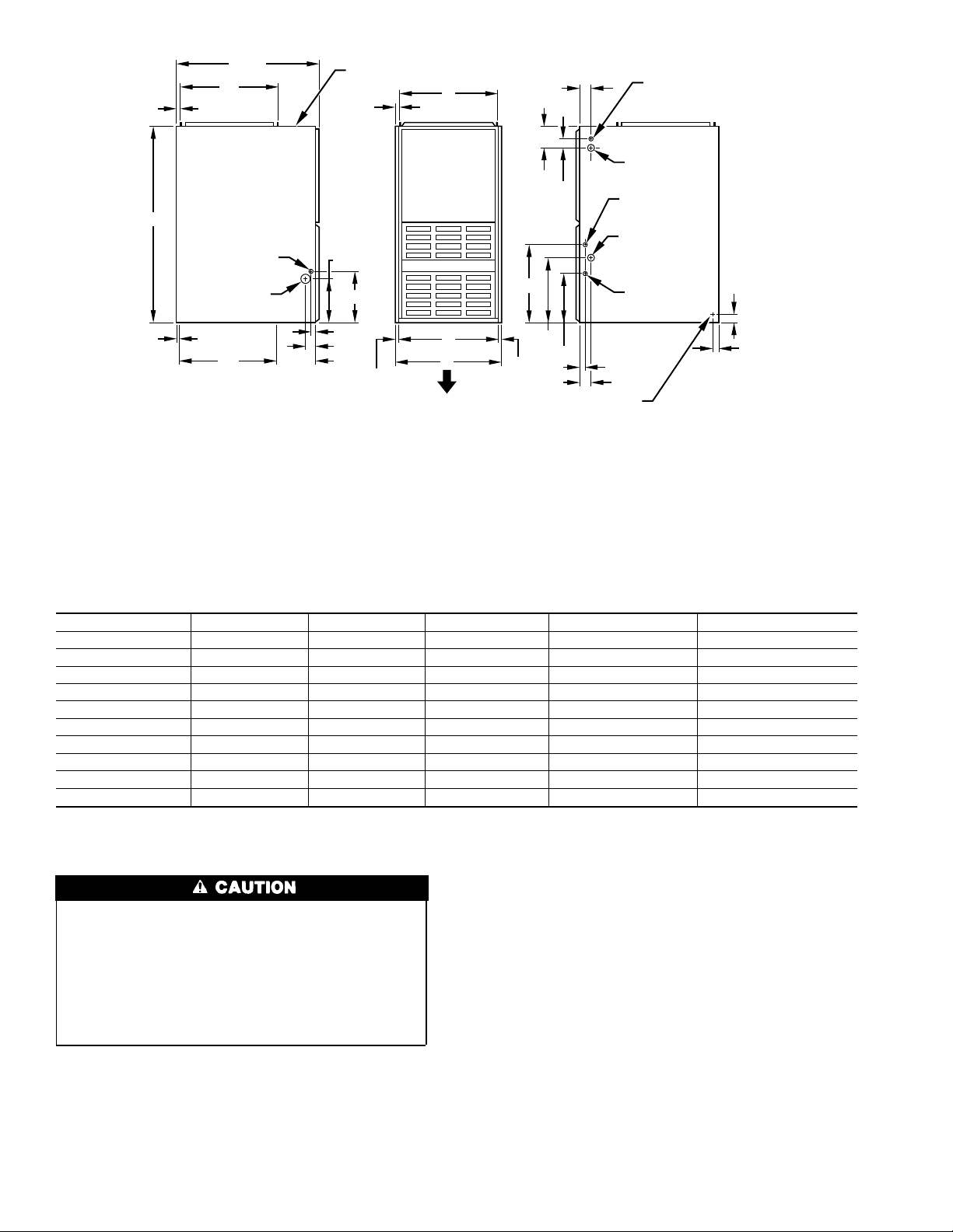
13
⁄16†
39 7⁄8†
11
⁄16†
28 1⁄2†
20†
INLET
7
⁄8† DIA
ACCESSORY
3
1
⁄4† DIA HOLE
GAS ENTRY
OUTLET
19†
NOTE:
ADDITIONAL
LOCA TED IN THE TOP PLA TE
AND BOTTOM PLATE
VENT CONNECTION
13
⁄16†
9 1⁄8†
10 1⁄4†
1 1⁄16†
2 1⁄8†
8 1⁄4†
11
⁄16†
7
⁄8† DIA K.O.’s ARE
D
E
A
AIRFLOW
1
⁄2† DIA
2†
4 3⁄16†
2 15⁄16†
16 1⁄16†
13 5 ⁄16†
10 1⁄4†
11
⁄16†
DIMPLES TO DRILL HOLES
FOR HANGER BOLTS (4 PLACES)
IN HORIZONTAL POSITION
THERMOSTAT
WIRE ENTRY
7
⁄8† DIA
ACCESSORY
7
⁄8† DIA HOLE
POWER ENTRY
1 1⁄2† DIA
R.H. GAS ENTRY
7
⁄8† DIA
ACCESSORY
1 1⁄16†
2 1⁄8†
† TYP
1
5
⁄8† TYP
NOTE:
Minimum return-air openings at furnace, based on metal duct. If flex duct is used,
see flex duct manufacturer's recommendations for equivalent diameters.
a. For 800 CFM–16-in. round or 141⁄2 x 12-in. rectangle.
b. For 1200 CFM–20-in. round or 141⁄2 x 191⁄2-in. rectangle.
c. For 1600 CFM–22-in. round or 141⁄2 x 231⁄4-in. rectangle.
d. For airflow requirements above 1800 CFM, must use entire return air opening.
→Fig. 1—Dimensional Drawing
Table 1—Dimensions (In.)
UNIT SIZE A D E VENT CONN SHIP. WT (LB)
050-08 14-3/16 12-9/16 12-11/16 4 124
050-12 14-3/16 12-9/16 12-11/16 4 128
070-08 14-3/16 12-9/16 12-11/16 4 129
070-12 14-3/16 12-9/16 12-11/16 4 137
096-12 17-1/2 15-7/8 16 4 146
096-16 17-1/2 15-7/8 16 4 151
115-16 17-1/2 15-7/8 16 4 159
115-20 21 19-3/8 19-1/2 4 174
115-22 21 19-3/8 19-1/2 4 176
135-20 24-1/2 22-7/8 23 5 193
ELECTROSTATIC DISCHARGE (ESD) PRECAUTIONS
PROCEDURE
3. After touching the chassis you may proceed to service the
control or connecting wires as long as you do nothing that
recharges your body with static electricity (for example; DO
NOT move or shuffle your feet, DO NOT touch ungrounded
Electrostatic discharge can affect electronic components.
Take precautions during furnace installation and servicing to
protect the furnace electronic control. Precautions will prevent electrostatic discharges from personnel and hand tools
which are held during the procedure. These precautions will
help to avoid exposing the control to electrostatic discharge
by putting the furnace, the control, and the person at the same
electrostatic potential.
1. Disconnect all power to the furnace. DO NOT TOUCH THE
CONTROL OR ANY WIRE CONNECTED TO THE CONTROL PRIOR TO DISCHARGING YOUR BODY’S ELECTROSTATIC CHARGE TO GROUND.
2. Firmly touch a clean, unpainted, metal surface of the furnace
chassis which is close to the control. Tools held in a person’s
hand during grounding will be satisfactorily discharged.
objects, etc.).
4. If you touch ungrounded objects (recharge your body with
static electricity), firmly touch furnace again before touching
control or wires.
5. Use this procedure for installed and uninstalled (ungrounded)
furnaces.
6. Before removing a new control from its container, discharge
your body’s electrostatic charge to ground to protect the
control from damage. If the control is to be installed in a
furnace, follow items 1 through 5 before bringing the control
or yourself into contact with the furnace. Put all used AND
new controls into containers before touching ungrounded
objects.
7. An ESD service kit (available from commercial sources) may
also be used to prevent ESD damage.
2
A99288
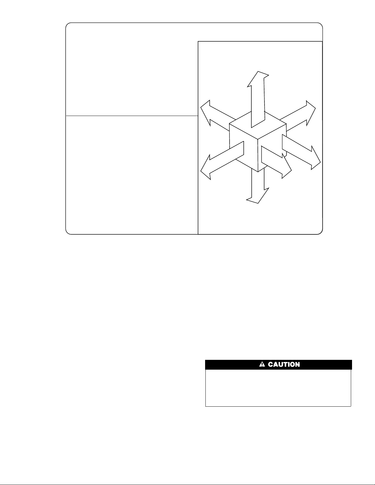
MINIMUM INCHES CLEARANCE TO COMBUSTIBLE CONSTRUCTION
This fo rced air furnace is equipped for use with natura l
gas at altitudes0-10,000ft (0-3,050m).
An accessory kit, supplied by the manu facturer,shall be
used to convert to propane gas use or may be required for
somenatura l gas applicatio ns.
This furnace is for indoor in stallatio n in a building
constructedonsite.
This furnace may be installed on combustible flooring in
alcove or closet at minimum clea rance from combustible
material.
This furnace may be used with a Type B-1 Vent and may
be vented in commonwithother gas-fired appliances.
For installation on non-combustible floorsonly.
†
For installation on combustible flooring only when
installedon special base, Part No. KGASB0201ALL,
Coil Assembly, Part No. CD5 or CK5, or Coil Casing,
Part No. KCAKC.
For furnaces wider than14.25 inches (362mm) may
#
be 0 inches.
18 inches front clearance requiredfor alcove.
Ø
Indicates supply or return sides whenfurnace isin
*
the horizontal position. Line contact only permissible
betweenlines formed by intersectionsof the Top and
two Sides of the furnace jacket, and building joists,
studs or framing.
For single wall vent type 6 inches.
##
For Type B-1 vent type 3 inches.
††
Clearance to Back 0 inches in downflowand
horizontal (attic/alcove& crawlspace) positionsand
3 inches in horizontal closet positions.
Fig. 2—Clearances to Combustibles
This f ur nace is approved f or DOWNFLOWand HORIZONTAL
installations.
Clearance arrows
do not change with
furnace orientation.
0"
†
†
B
A
C
K
E
D
I
S
1" #
*
Clearance in inches
1"
TOP / PLENUM
E
C
A
N
R
U
F
1
†
T
N
O
R
F
F
R
BOTTOM
#
"
S
O
N
T
##
Ø
1"
#
E
*
D
I
S
E
R
V
I
C
E
30"
Vent Clearance to combustibles:
For Single Wall vents 6 i nches.
For Type B-1 vent type 1 inch.
322286-101REV.F (LIT)
MIN
A99262
INTRODUCTION
The model 58ZAV Series 140 Furnaces are available in sizes
46,000 through 135,000 Btuh input capacities.
The design of the downflow/horizontal gas-fired furnace is
A.G.A./C.G.A. certified for natural and propane gases and for
installation on noncombustible flooring. The furnace is factoryshipped for use with natural gas. A factory accessory gas conversion kit, as listed on the furnace rating plate is required to convert
furnace for use with propane gas.
These furnaces SHALL NOT be installed directly on carpeting,
tile, or any other combustible material other than wood flooring. In
downflow installations, a factory accessory floor base, as listed on
the furnace rating plate MUST be used when installed on combustible materials and wood flooring. A factory base is not
required when this furnace is installed on manufacturer’s Coil
Assembly Part No. CD5 or CK5, or when Coil Box Part No.
KCAKC is used. This furnace is for installation in alcoves, attics,
crawlspaces, basements, closets, or utility rooms. The design of
this furnace line is not A.G.A./C.G.A. certified for installation in
mobile homes, recreation vehicles, or outdoors.
Before installing the furnace in the United States, refer to the
current edition of the NFGC and the NFPA 90B. For further
information, the NFGC and NFPA 90B are available from National Fire Protection Association Inc., Batterymarch Park,
Quincy, MA 02269; or the American Gas Association, 400 N.
Capitol St., NW, Washington DC 20001.
Before installing the furnace in Canada, refer to the current edition
→
of the NSCNGPIC. For a copy of the NSCNGPIC, contact
Standard Sales, CSA International, 178 Rexdale Boulevard, Etobicoke (Toronto), Ontario, M9W 1R3 Canada.
Installation must comply with regulations of serving gas supplier
and local building, heating, plumbing or other codes in effect in the
area in which installation is made. In absence of local building
codes, installation must conform with NFGC in the United States
and the NSCNGPIC and all authorities having jurisdiction in
Canada.
These instructions cover minimum requirements for a safe installation and conform to existing national standards and safety codes.
In some instances, these instructions exceed certain local codes
and ordinances, especially those that may not have kept pace with
changing residential construction practices. We require these
instructions as a minimum for a safe installation.
Application of this furnace should be indoors with special
attention given to vent sizing and material, gas input rate, air
temperature rise, and unit sizing. Improper installation or
misapplication of the furnace can require excessive servicing
or cause premature component failure.
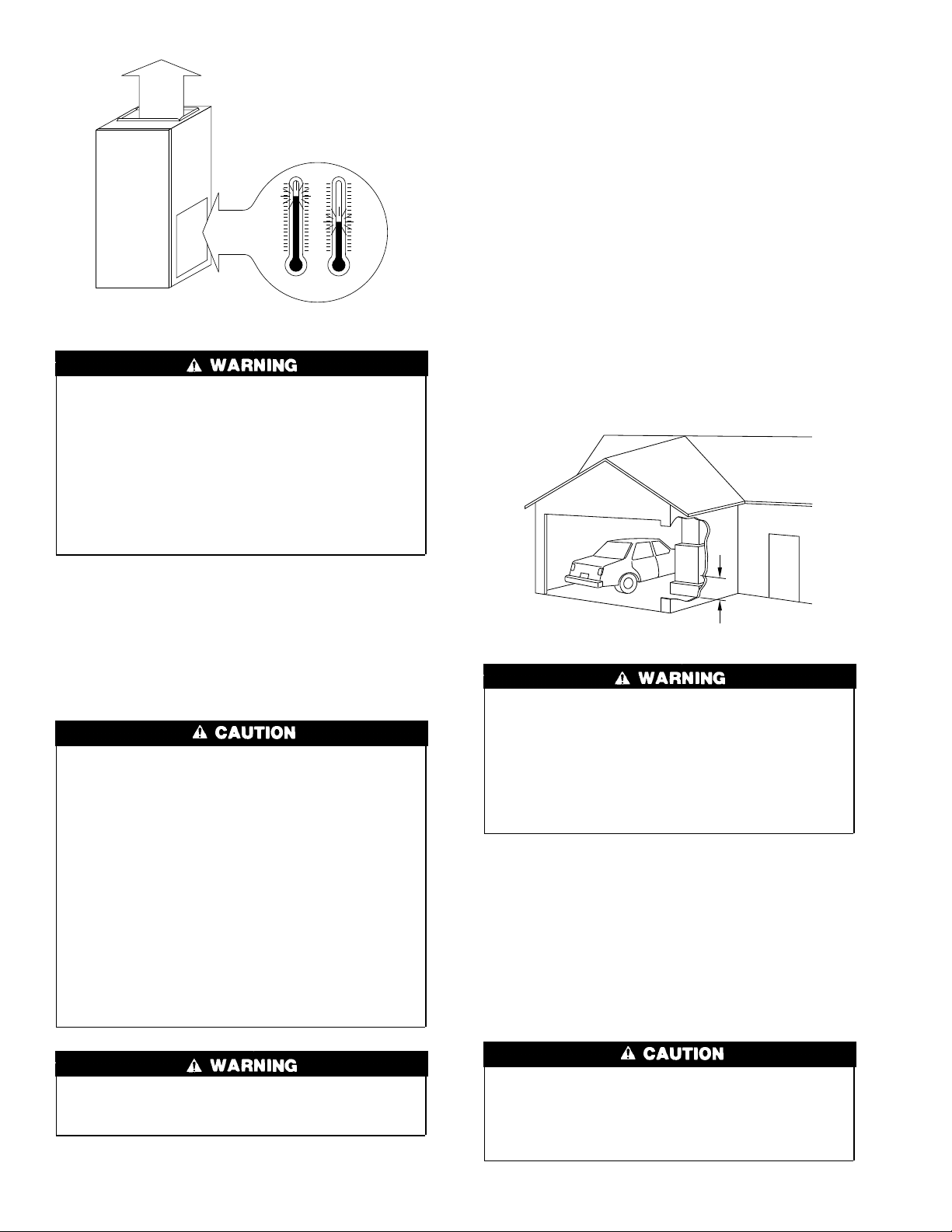
NOTE: These furnaces are designed for a minimum continuous
return-air temperature of 60°F or intermittent operation down to
55°F such as when used with a night setback thermostat. Return-air
temperature must not exceed a maximum of 85°F. Failure to
follow these return-air temperature limits may affect reliability of
heat exchangers, motors, and controls.
3
FRONT
°F °F
RETURN
AIR
MAX 85°F MIN 55°F
A93042
Improper installation, adjustment, alteration, service, maintenance, or use can cause carbon monoxide poisoning, explosion, fire, electrical shock, or other conditions which may
cause personal injury, loss of life, or property damage.
Consult a qualified installer, service agency, local gas supplier, or your distributor or branch for information or assistance. The qualified installer or agency must use only
factory-authorized and listed kits or accessories when modifying this product. Failure to follow this warning could result
in electrical shock, fire, personal injury, or death.
Locate the furnace as close to the chimney/vent and as near the
center of the air distribution system as possible. The furnace
should be installed as level as possible.
Provide ample space for servicing and cleaning. Always comply
with the minimum fire protection clearances shown on the unit
rating plate. This furnace shall not be installed directly on
carpeting, tile, or any combustible material other than wood
flooring. The furnace may be installed on combustible flooring
when installed with the accessory downflow subbase, which is
available from your distributor or branch when required.
LOCATION RELATIVE TO COOLING EQUIPMENT — The
cooling coil must be installed parallel with or on the downstream
side of the furnace to avoid condensation in the heat exchangers.
When installed parallel with a furnace, dampers or other means
used to control the flow of air must prevent chilled air from
entering the unit. If the dampers are manually operated, they must
be equipped with means to prevent operation of either unit unless
the damper is in the full-heat or full-cool position.
HAZARDOUS LOCATIONS
For accessory installation details, refer to the applicable installation literature.
NOTE: Remove all shipping brackets and materials before operating the furnace.
Step 1—Location
GENERAL
Do not install furnace in a corrosive or contaminated atmosphere. Make sure all combustion and circulating air requirements are followed, in addition to all local codes and
ordinances.
Do not use this furnace during construction when adhesives,
sealers, and/or new carpets are being installed. If the furnace
is required during construction, use clean outside air for
combustion and ventilation. Compounds of chlorine and
fluorine when burned with combustion air form acids which
cause corrosion of the heat exchangers and metal vent system.
Some of these compounds are found in paneling and dry wall
adhesives, paints, thinners, masonry cleaning materials, and
many other solvents commonly used in the construction
process.
Excessive exposure to contaminated combustion air will
result in safety and performance related problems.
18-IN. MINIMUM
TO BURNERS
A93044
When furnace is installed in a residential garage, it must be
installed so that burners and ignition sources are located a
minimum of 18 in. above floor. The furnace must be located
or protected to avoid physical damage by vehicles. When
furnace is installed in a public garage, airplane hangar, or
other building having a hazardous atmosphere, unit must be
installed in accordance with requirements of National Fire
Protection Association, Inc.
Step 2—Air For Combustion and Ventilation
Provisions for adequate combustion and ventilation air must be
provided in accordance with Section 5.3 of the NFGC, Air for
Combustion and Ventilation, or applicable provisions of the local
building codes.
Canadian installations must be installed in accordance with NSCNGPIC and all authorities having jurisdiction.
Do not install the furnace on its back; safety control operation
will be adversely affected. Failure to follow this warning
could result in fire, personal injury, or death.
This furnace must be installed so the electrical components are
protected from water.
Air for combustion must not be contaminated by halogen
compounds, which include fluoride, chloride, bromide, and
iodide. These elements are found in aerosol sprays, detergents, bleaches, cleaning solvents, salts, air fresheners, and
other household products.
4
The operation of exhaust fans, kitchen ventilation fans,
clothes dryers, or fireplaces could create a NEGATIVE
PRESSURE CONDITION at the furnace. Make-up air MUST
be provided for the ventilation devices, in addition to that
required by the furnace.
All fuel-burning equipment must be supplied with air for combustion of the fuel. Sufficient air MUST be provided to ensure there
will not be a negative pressure in the equipment room or space. In
addition, a positive seal MUST be made between the furnace
cabinet and the return-air duct to avoid pulling air from the burner
area and blocked vent safeguard opening.
The requirements for combustion and ventilation air depend upon
whether the furnace is located in an unconfined or confined space.
UNCONFINED SPACE — An unconfined space must have at
least 50 cu ft for each 1000 Btuh of input for all the appliances
(such as furnaces, clothes dryer, water heaters, etc.) in the space.
If the unconfined space is of unusually tight construction, air for
For Example:
58ZAV FURNACE
INPUT BTUH
46,000 307
69,000 460
92,000 613
115,000 767
135,000 920
MINIMUM SQ FT
WITH
7-1/2 FT CEILING
combustion and ventilation MUST come from either the outdoors
or spaces freely communicating with the outdoors. Combustion
and ventilation openings must be sized the same as for a confined
space as defined below. Return air must not be taken from the
room unless an equal or greater amount of air is supplied to the
room.
CONFINED SPACE
A confined space is defined as a space whose volume is less than
50 cu ft per 1000 Btuh of total input ratings of all appliances
installed in that space. A confined space MUST have provisions
for supplying air for combustion, ventilation, and dilution of flue
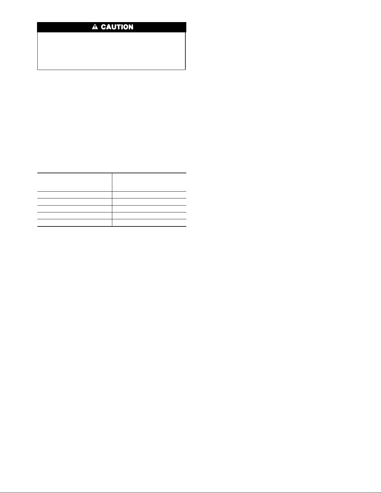
gases using 1 of the following methods. (See Fig. 3 and 4 and
Table 2.)
NOTE: In determining free area of an opening, the blocking
effect of louvers, grilles, and screens must be considered. If free
area of louver or grille design is unknown, assume that wood
louvers have a 20 percent free area and metal louvers or grilles
have a 60 percent free area. Screens, when used, must not be
smaller than 1/4-in. mesh. Louvers and grilles must be constructed
so they cannot be closed.
The size of the openings depends upon whether air comes from
outside of the structure or an unconfined space inside the structure.
1. All air from inside the structure requires 2 openings (for
structures not usually tight):
a. Each opening MUST have at least 1 sq in. of free area per
1000 Btuh of total input for all equipment within the
confined space, but not less than 100 sq in. per opening.
(See Fig. 3 and Table 2.) The minimum dimension of air
openings shall not be less than 3 in.
b. If building is constructed unusually tight, a permanent
opening directly communicating with the outdoors shall be
provided. See item 2 below.
c. If furnace is installed on a raised platform to provide a
return-air plenum, and return air is taken directly from
hallway or space adjacent to furnace, all air for combustion
must come from outdoors.
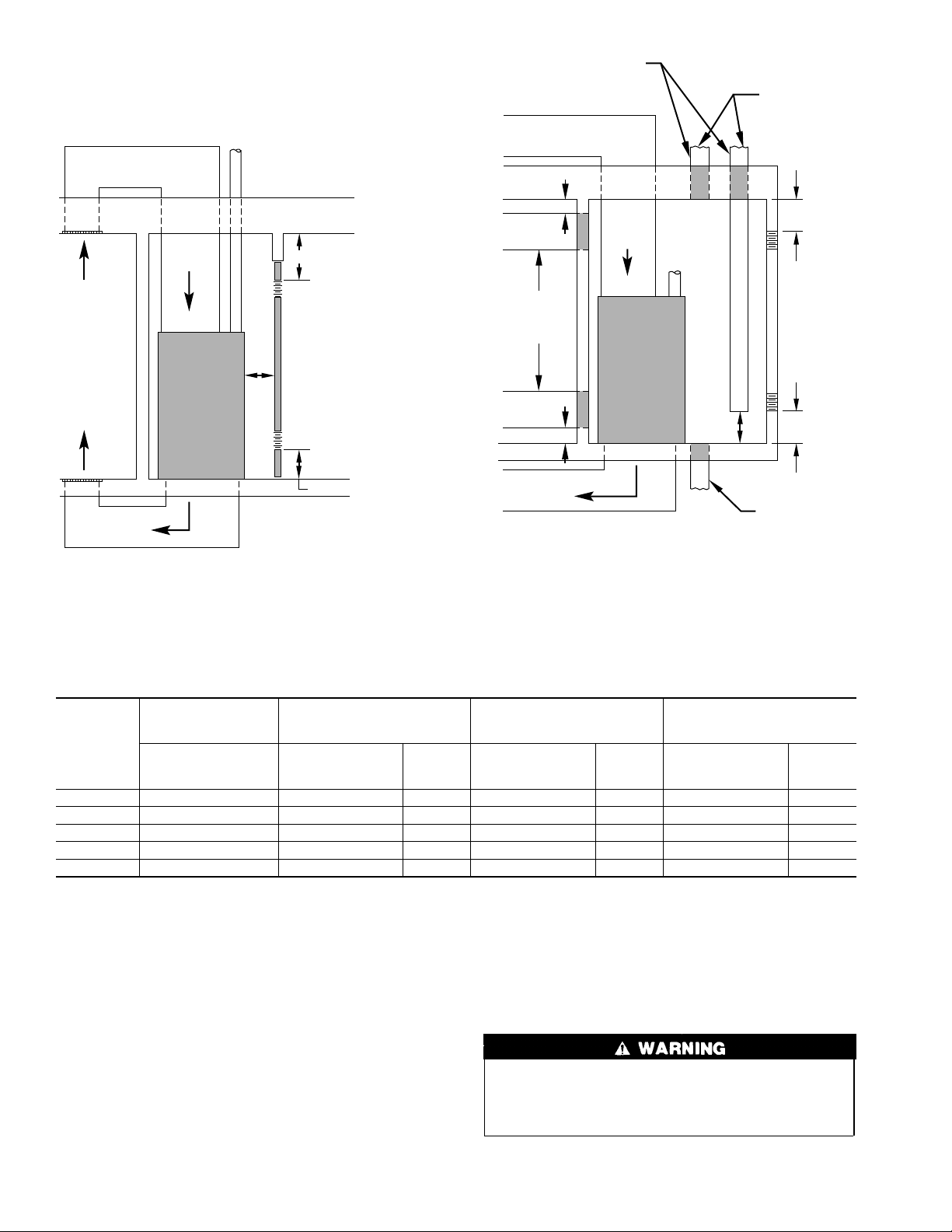
2. Air from outside the structure requires 1 of the following
methods:
a. If combustion air is taken from outdoors through 2 vertical
ducts, the openings and ducts MUST have at least 1 sq in.
of free area per 4000 Btuh of total input for all equipment
within the confined space. (See Fig. 4 and Table 2.)
b. If combustion air is taken from outdoors through 2 hori-
zontal ducts, the openings and ducts MUST have at least 1
sq in. of free area per 2000 Btuh of total input for all
equipment within the confined space. (See Fig. 4 and Table
2.)
c. If combustion air is taken from outdoors through a single
opening or duct (horizontal or vertical) commencing within
12 in. of the top of the confined space, opening and duct
MUST have at least 1 sq in. of free area per 3000 Btuh of
the total input for all equipment within the confined space
and not less than the sum of the areas of all vent connectors
in the confined space. (See Fig. 4 and Table 2.) Equipment
clearances to the structure shall be at least 1 in. from the
sides and back and 6 in. from the front of the appliances.
When ducts are used, they must be of the same cross-sectional area
as the free area of the openings to which they connect. The
minimum dimension of ducts must not be less than 3 in. (See Fig.
4.)
AIR DUCTS
Step 1—General Requirements
The duct system should be designed and sized according to
accepted national standards such as those published by: Air
Conditioning Contractors Association (ACCA), Sheet Metal and
Air Conditioning Contractors National Association (SMACNA) or
American Society of Heating, Refrigerating and Air Conditioning
Engineers (ASHRAE). Or consult factory The Air Systems Design
Guidelines reference tables available from your local distributor.
The duct system should be sized to handle the required system
design CFM at the design static pressure.
When a furnace is installed so that the supply ducts carry air to
areas outside the space containing the furnace, the return air must
also be handled by a duct(s) sealed to the furnace casing and
terminating outside the space containing the furnace.
Secure ductwork with proper fasteners for type of ductwork used.
Seal supply- and return-duct connections to furnace with code
approved tape or duct sealer.
Flexible connections should be used between ductwork and
furnace to prevent transmission of vibration. Ductwork passing
through unconditioned space should be insulated to enhance
system performance. When air conditioning is used, a vapor
barrier is recommended.
Maintain a 1-in. clearance from combustible materials to supply air
ductwork for a distance of 36 in. horizontally from the furnace. See
NFPA 90B or local code for further requirements.
Step 2—Ductwork acoustical treatment
Metal duct systems that do not have a 90 degree elbow and 10 ft
of main duct to the first branch take-off may require internal
acoustical lining. As an alternative, fibrous ductwork may be used
if constructed and installed in accordance with the latest edition of
SMACNA construction standard on fibrous glass ducts. Both
acoustical lining and fibrous ductwork shall comply with NFPA
90B as tested by UL Standard 181 for Class 1 Rigid air ducts.
5
VENT THROUGH ROOF
(CATEGORY I)
DUCTS TO
OUTDOORS
1 SQ IN.
PER 4000
BTUH
*
RETURN
AIR
INTERIOR
HEATED
SPACE
SUPPLY AIR
* Minimum opening size is 100 sq in. with
minimum dimensions of 3 in.
†
Minimum of 3 in. when type B-1 vent is used.
12″ MAX
1 SQ IN.
PER 1000
BTUH* IN DOOR
OR WALL
UNCONFINED
SPACE
6″ MIN
(FRONT)
1 SQ IN.
PER 1000
BTUH* IN DOOR
OR WALL
†
12″ MAX
A93387
Fig. 3—Confined Space: Air for Combustion and
Ventilation from an Unconfined Indoor Space
12″ MAX
1 SQ IN.
PER 2000
BTUH
*
DUCTS
TO
OUTSIDE
1 SQ IN.
PER 2000
BTUH
*
12″ MAX
SUPPLY AIR
Minimum dimensions of 3 in.
*
Use any of the following
NOTE:
combinations of openings:
A & B C & D D & E F & G
RETURN
A
B
AIR
D
VENT
THROUGH
ROOF
(CATEGORY I)
CONFINED
C
DUCT
TO
OUTDOORS
F
SPACE
G
E
12″ MAX
12″
MAX
1 SQ IN.
PER 4000
BTUH
OUTDOORS
1 SQ IN.
PER 4000
BTUH
12″
MAX
1 SQ IN.
PER 4000
BTUH
*
*
A93388
Fig. 4—Confined Space: Air for Combustion and
Ventilation from Outdoors
→Table 2—Minimum Free Area Of Combustion Air Opening
AIR FROM UNCON-
58ZAV
FURNACE
INPUT
(BTUH)
46,000 100 11.50 4 23.0 6 15.33 5
69,000 100 17.25 5 34.5 7 23.00 6
92,000 100 23.00 6 46.0 8 30.67 7
115,000 115 28.75 7 57.5 9 38.33 7
135,000 135 33.75 7 67.5 10 45.00 8
* Free area shall be equal to or greater than the sum of the areas of all vent connectors in the confined space. Opening area must be increased if other gas appliances
in the space require combustion air.
FINED INDOOR
SPACE
Free Area
of Opening
(Sq In.)
Step 3—Supply Air Connections
DOWNFLOW FURNACES
Connect supply-air duct to supply-air opening on furnace. The
supply-air duct attachment must ONLY be connected to furnace
supply/outlet or air conditioning coil casing (when used), when
installed on non-combustible material. When installed on combustible material, supply-air duct attachment must ONLY be connected to an accessory subbase or factory approved air conditioning coil casing. DO NOT cut main furnace casing to attach supply
side air duct, humidifier, or other accessories. All accessories
MUST be connected external to furnace main casing.
HORIZONTAL FURNACES
Connect supply-air duct to supply air opening on furnace. The
supply-air duct attachment must ONLY be connected to furnace
OUTDOOR AIR THROUGH
VERTICAL DUCTS
Free Area of
Opening and Duct
(Sq In.)
Round
Pipe
(In. Dia)
OUTDOOR AIR THROUGH
HORIZONTAL DUCTS
Free Area of
Opening and Duct
(Sq In.)
Round
Pipe
(In. Dia)
OUTDOOR AIR THROUGH
SINGLE DUCT
Free Area of
Opening and Duct
(Sq In.)
Round
Pipe
(In. Dia)
supply/outlet or air conditioning coil casing (when used). DO NOT
cut main furnace casing to attach supply side air duct, humidifier,
or other accessories. All accessories MUST be connected external
to furnace main casing.
Step 4—Return Air Connections
Do not install the furnace on its back or sides. Safety control
operation will be adversely affected. Never connect return-air
ducts to the back of the furnace. A failure to follow this
warning can cause a fire, personal injury, or death.
The return-air duct must be connected to return-air opening
provided as shown in Fig. 1. DO NOT cut into casing sides or back
6
 Loading...