

Page 1
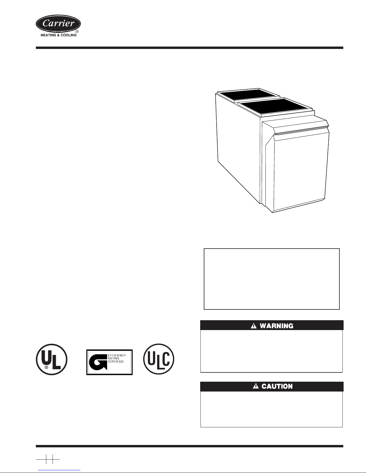
Oil Furnace
Visit www.carrier.com
Installation, Start-Up, and Operating Instructions
For Input Capacities of 70,000—154,000; Series 100
NOTE: Read the entire instruction manual before starting the
installation.
This symbol → indicates a change since the last issue.
TABLE OF CONTENTS
SAFETY CONSIDERATIONS.....................................................1
INTRODUCTION..........................................................................3
LOCATION....................................................................................3
General......................................................................................3
Location Relative to Cooling Equipment ................................4
INSTALLATION...........................................................................4
Air for Combustion and Ventilation........................................4
General......................................................................................4
Unconfined Space................................................................4
Confined Space....................................................................5
Duct Work Recommendations..................................................5
Venting......................................................................................6
Oil Burner .................................................................................7
Oil Connections ........................................................................7
Barometric Draft Control..........................................................7
Electrical Connections..............................................................7
Filters.......................................................................................10
STARTUP, ADJUSTMENT, AND SAFETY CHECKOUT .....10
Operational Checkout .............................................................10
Sequence of Operation............................................................10
Combustion Check..................................................................11
Fan Adjustment Check ...........................................................12
Limit Control Check...............................................................14
For Year-Round Air Conditioning.........................................14
CARE AND MAINTENANCE...................................................14
General....................................................................................14
Oil Burner ...............................................................................14
Heat Exchanger and Flue Pipe...............................................14
Blower Removal .....................................................................14
ama
→ Fig. 1—58VLR Low-Boy Oil Furnace
SAFETY CONSIDERATIONS
FOR YOUR SAFETY
DO NOT STORE OR USE GASOLINE OR OTHER
FLAMMABLE VAPORS AND LIQUIDS IN THE VICINITY OF THIS OR ANY OTHER APPLIANCE.
DO NOT ATTEMPT TO START THE BURNER
WHEN EXCESS OIL HAS ACCUMULATED, WHEN
THE FURNACE IS FULL OF VAPOR, OR WHEN
THE COMBUSTION CHAMBER IS VERY HOT.
CARBON MONOXIDE POISONING FIRE
EXPLOSION HAZARD
Failure to follow this warning could lead to sooting, fire,
explosion, and/or severe bodily harm.
For use with grade 1 or 2 Fuel Oil. Do not use Gasoline,
Crankcase Oil, or any Oil containing gasoline!
58VLR
Low-Boy
A05024
Manufacturer reserves the right to discontinue, or change at any time, specifications or designs without notice and without incurring obligations.
Book 1 4
Tab 6a 8a
PC 101 Catalog No. 535-80171 Printed in U.S.A. Form 58VLR-2SI Pg 1 2-05 Replaces: 58VLR-1SI
FIRE HAZARD
Failure to follow this caution may result in fire and property
damage.
Never burn garbage or paper in the heating system and never
leave rags, paper, or any flammable items around the unit.
Page 2
VENT
CONN
21 1⁄4″
20"20"20"
10"
3"
D
C
E
B
A
Dimensions (In.)
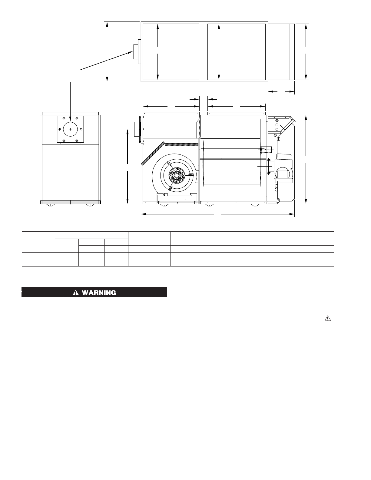
UNIT DIMENSIONS
UNIT SIZE
105–12 21-1/4 53-3/4 31-1/2 26-1/2 20 20 5
120–20 21-1/4 60-5/32 34-3/4 28-11/32 22 24 6
Width
Depth Height
AB C D E
FLUE HEIGHT RETURN OPENING SUPPLY OPENING VENT CONNECTION
Fig. 2—Dimensional Drawing
Only the latest issues of these codes should be used, and are
available from either The National Fire Protection Agency, Bat-
UNIT RELIABILITY HAZARD
→
These instructions are intended to be used by qualified
personnel who have been trained in installing this type of
furnace. Installation of this furnace by an unqualified person
may lead to equipment damage and/or a hazardous condition
which may lead to bodily harm.
All local and national code requirements governing installation of
oil burning equipment, wiring, and flue connections must be
followed. Some of the codes (issued by the Canadian Standards
Association, the National Fire Protection Agency, and/or the
American National Standards Institute) that may be applicable are:
ANSI/NFPA 31: INSTALLATION OF OIL BURNING EQUIPMENT
ANSI/NFPA 211: CHIMNEYS, FIREPLACES, VENTS, AND
SOLID FUEL BURNING APPLIANCES
ANSI/NFPA 90B: WARM AIR HEATING AND AIR CONDITIONING SYSTEMS
ANSI/NFPA 70: NATIONAL ELECTRIC CODE
terymarch Park, Quincy, MA 02269 or The Canadian Standards
Association, 178 Rexdale Blvd., Rexdale, Ontario M9W 1R3
Recognize safety information. This is the safety-alert symbol
When you see this symbol on the furnace and in instructions or
manuals, be alert to the potential for personal injury.
Understand the signal words DANGER, WARNING, and CAUTION. These words are used with the safety-alert symbol. DANGER identifies the most serious hazards which will result in severe
personal injury or death. WARNING signifies a hazard which
could result in personal injury or death. CAUTION is used to
identify unsafe practices which may result in minor personal
injury or product and property damage. NOTE is used to highlight
suggestions which will result in enhanced installation, reliability,
or operation.
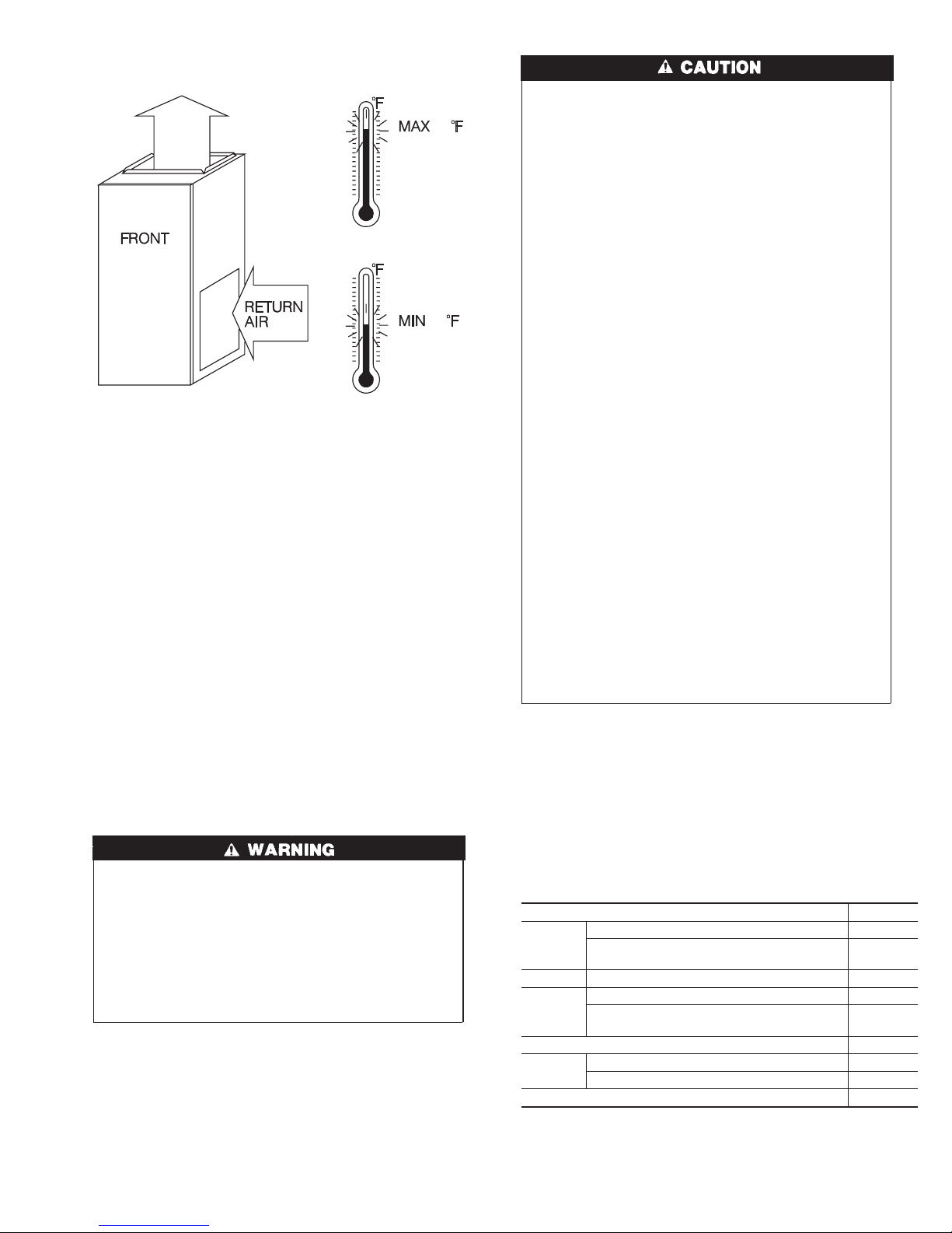
This furnace is designed for continuous return-air minimum
→
temperature of 60°F db or intermittent operation down to 55°F db
such as when used with a night setback thermostat. Return-air
temperature must not exceed 80°F db. Failure to follow these
return air limits may affect reliability of heat exchangers, motors
and controls. (See Fig. 3.)
CSA B139: INSTALLATION CODE FOR OIL BURNING
EQUIPMENT
CAS C22.1: CANADIAN ELECTRICAL CODE
2
A98009
.
Page 3
→
Fig. 3—Return-Air Temperature
INTRODUCTION
The model 58VLR Furnaces are available in 2 sizes. Each size can
be fired at 3 different rates by a simple nozzle change. Unit
58VLR105 covers input ranges from 70,000 to 105,000 Btuh. Unit
58VLR120 covers input ranges from 119,000 to 154,000 Btuh.
This furnace is a Low-Boy unit. It may be operated only in the
upflow configuration.
The furnace is shipped as a packaged unit, complete with burner
and controls. It requires a line voltage (115 vac) connection to
control box, a thermostat hook-up as shown on wiring diagram, oil
line connection(s), adequate duct work, and connection to a
properly sized vent.
The air handling capacity of this furnace is designed for cooling
airflow. Refer to Table 13 or 14 for expected airflows at various
external duct static pressures.
LOCATION
Step 1—General
80
60
A04036
UNIT DAMAGE HAZARD
This oil furnace may be used for construction heat provided
that:
-The furnace operating conditions, including ignition, input
rate, temperature rise and venting, are verified per instructions in this manual.
-The furnace is permanently installed with all electrical
wiring, piping, venting and ducting installed according to
these installation instructions. A return air duct is provided,
sealed to the furnace casing, and terminated outside the space
containing the furnace. This prevents a negative pressure
condition as created by the circulating air blower, causing a
flame rollout and/or drawing combustion products into the
structure.
-The furnace is controlled by a thermostat. It may not be ″hot
wired″ to provide heat continuously to the structure without
thermostatic control.
-Clean outside air is provided for combustion. This is to
minimize the corrosive effects of adhesives, sealers and other
construction materials. It also prevents the entrainment of
drywall dust into combustion air, which can cause fouling and
plugging of furnace components.
-The temperature of the return air to the furnace is no less
than 55°F, with no evening setback or shutdown. The use of
the furnace while the structure is under construction is
deemed to be intermittent operation per our installation
instructions.
-The air temperature rise is within the rated rise range on the
furnace rating plate, and the firing rate has been set to the
nameplate value.
-The filters used to clean the circulating air during the
construction process must be either changed or thoroughly
cleaned prior to occupancy.
-The furnace, ductwork and filters are cleaned as necessary to
remove drywall dust and construction debris from all HVAC
system components after construction is completed.
This furnace is approved for reduced clearances to combustible
construction, therefore, it may be installed in a closet or similar
enclosure. It may be located in a basement or on the same level as
area to be heated. In any case, unit should always be installed level.
The required minimum clearances for this furnace are specified in
Table 1.
ELECTRICAL SHOCK, FIRE OR UNIT DAMAGE
HAZARD
Failure to follow this warning could result in property damage
or personal injury or death.
This furnace is not water tight and is not designed for outdoor
installation. This furnace shall be installed in such a manner
as to protect electrical components from water. Outdoor
installation would lead to a hazardous electrical condition and
to premature furnace failure.
Table 1—Minimum Clearances to Combustible
Materials (In.)
UNIT APPLICATION LOW-BOY
Furnace 1
Sides
Back Service Clearance 19
Top
Bottom* 0
Flue Pipe
Front 8
*Floor may be combustible
NOTE: Adequate service clearance should be provided over and above these
dimensions as required.
Supply Plenum and Warm-Air Duct within 6 ft
of Furnace
Furnace Casing or Plenum 2
Horizontal Warm-Air Duct Within 6 ft
of Furnace
Horizontally or Below Pipe 4
Vertically Above Pipe 9
3
1
2
Page 4
The furnace should be located as close as possible to chimney or
vent in order to keep vent connections short and direct. The
furnace should also be located as near as possible to center of air
distribution system.
Step 2—Location Relative to Cooling Equipment
When installing furnace with cooling equipment for year-round
operation, the following recommendations must be followed for
series or parallel airflow:
1. In series airflow applications, coil is mounted after furnace in
an enclosure in supply-air stream. The furnace blower is used
for both heating and cooling airflow.
UNIT DAMAGE HAZARD
→
Failure to follow this caution may reduce the life of this unit.
The coil MUST be installed on air discharge side of furnace.
Under no circumstances should airflow be such that cooled,
conditioned air can pass over furnace heat exchanger. This
will cause condensation in heat exchanger and possible
failure of heat exchanger which could lead to a fire hazard
and/or a hazardous condition which may lead to bodily harm.
Heat exchanger failure due to improper installation may not
be covered by warranty.
2. In parallel airflow applications, dampers must be provided to
direct air over furnace heat exchanger when heat is desired and
over cooling coil when cooling is desired.
IMPORTANT: The dampers should be adequate to prevent cooled
air from entering furnace. If manually operated, dampers must be
equipped with a means to prevent operation of either cooling unit
or furnace unless damper is in full cool or heat position.
INSTALLATION
Step 1—Air for Combustion and Ventilation
CARBON MONOXIDE POISONING AND UNIT
CORROSION HAZARD
Failure to follow this warning could lead to premature rusting
of heat exchanger and possible premature furnace failure
and/or vent failure which could result in fire hazard and/or
personal injury or death.
Installation of this furnace in an area where it will receive
contaminated combustion air must be avoided. Such contamination would include the following: ammonia, chlorine,
hydrogen sulfide, halogenated hydrocarbons, carbon tetrachloride, cleaning solvents, hydrochloric acid, water softening chemicals, and similar chemicals.
CARBON MONOXIDE POISONING AND FIRE
HAZARD
Failure to follow this warning could result in property
damage, personal injury or death.
Do not block combustion-air openings in the furnace. Any
blockage could result in improper combustion.
Step 2—General
This furnace should be installed in a location in which facilities for
ventilation permit satisfactory combustion of oil, proper venting,
and maintenance of ambient temperature at safe limits under
normal conditions of use. The location should not interfere with
proper circulation of air within the confined space. (See NFPA-31,
Section 1.5.)
In addition to air needed for combustion, process air shall be
provided as required for: cooling of equipment or material,
controlling dew point, heating, drying, oxidation or dilution, safety
exhaust, and odor control.
In addition to air needed for combustion, air shall be supplied for
ventilation, including all air required for comfort and proper
working conditions for personnel.
The barometric draft regulator (included with furnace) shall be
installed in same room or enclosure as furnace in such a manner as
to prevent any difference in pressure between regulator and
combustion-air supply.
Air requirements for operation of exhaust fans, kitchen ventilation
systems, clothes dryers, and fireplaces shall be considered in
determining the adequacy of a space to provide combustion-air
requirements.
The lack of a proper amount of combustion air can lead to serious
furnace operational problems. Some of these problems are:
1. Excessive oil burner after drip and oil fumes.
2. Sooting.
3. Melted igniter/relay control.
4. Air band or air turbulator settings more open than normal.
5. Lockouts on start-up.
The requirements for combustion and ventilation air depend upon
whether the furnace is located in a CONFINED or UNCONFINED
space.
UNCONFINED SPACE
An unconfined space must have at least 50 cu ft for each 1000
Btuh of total input for all the appliances (such as furnaces, clothes
dryers, water heaters, etc.) in the space. (Refer to Table 2.)
Table 2—Minimum Floor Area for Unconfined
Space
58VLR FURNACE
INPUT BTUH
70,000 467
91,000 607
105,000 700
119,000 793
140,000 933
154,000 1028
In unconfined spaces in buildings of conventional frame, brick, or
stone construction, infiltration MAY be adequate to provide air for
combustion, ventilation, and dilution of flue gases. This determination must be made on an individual installation basis and must
take into consideration the overall volume of unconfined space, the
number of windows and ventilation openings, the number of doors
to the outside, internal doors which can close off unconfined space,
and overall tightness of building construction. Consideration must
also be given to the amount of storage items (furniture, boxes, etc.)
within the unconfined space which take away from the air volume.
Many new buildings and homes (and older ones that have been
weatherized) MUST BE considered as being of tight construction,
therefore, infiltration will not be sufficient to supply necessary air
for combustion and ventilation.
A building can be considered as being of tight construction when:
1. Walls and ceilings exposed to outside atmosphere have a
continuous water vapor retarder with a rating of 1 perm or less
with openings gasketed or sealed, and/or
MINIMUM SQ FT WITH
7-1/2 FT CEILING
4
Page 5
2. Weatherstripping has been added on operable windows and
doors, and/or
3. Caulking or sealants are applied to areas such as joints around
window and door frames; between sole plates and floors;
between wall-ceiling joints; between wall panels; at penetrations for plumbing, electrical, and fuel lines; and at other
openings.
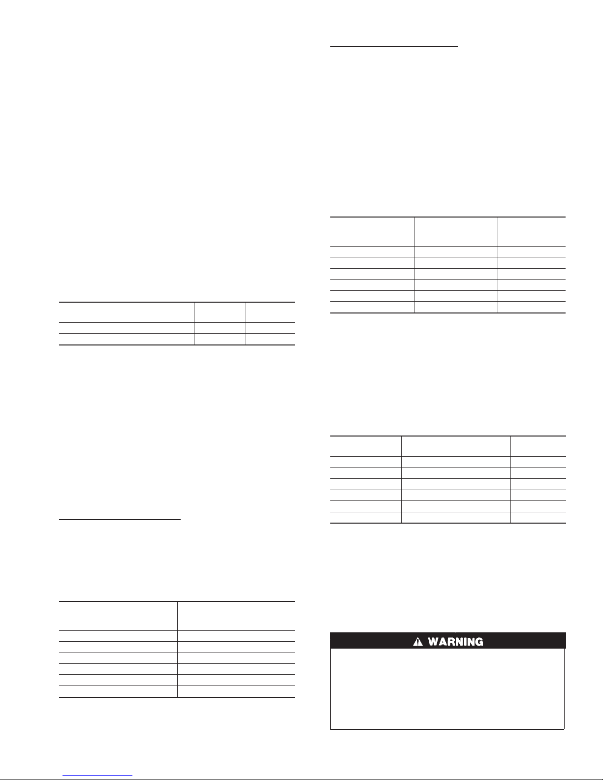
If combustion and ventilation air must be supplied to an unconfined space from outside, an opening with a FREE AREA of not
less than 1 sq in. per 1000 Btuh of total input of all appliances
within unconfined space (but not less than 100 sq in.) must be
provided. This opening must be located such that it can not be
blocked at any time.
CONFINED SPACE
A confined space has a volume of less than 50 cu ft per 1000 Btuh
of the total input rating for all appliances installed in that space.
When furnace is installed in a closet or enclosure, 2 ventilation
openings, with OPEN AREA as dimensioned in example below
are required for combustion air. The openings should be located
about 6 in. from top and bottom of enclosure at front of furnace.
(Refer to Table 3.)
Table 3—Combustion Air From Confined Space
58VLR FURNACE INPUT BTUH
70,000-105,000 16 8
119,000-154,000 20 10
LENGTH
(IN.)
NOTE: In calculating free area, consideration shall be given to
blocking effect of louvers, grilles, or screens protecting openings.
Screens used shall not be smaller than 1/4-in. mesh and shall be
readily accessible for cleaning. If free area through a design of
louver or grille is known, it shall be used in calculating size design
and free area specified. If design and free area are not known, it
may be assumed that wood louvers have 20 percent free area and
metal louvers and grilles have 60 percent free area. Louvers shall
be fixed in open position or interlocked with furnace so they open
automatically at furnace start-up and remain open during furnace
operation.
The size of the openings depends upon whether the air comes from
outside of the structure or an unconfined space inside the structure.
All Air From Inside the Structure
For a confined space, where air is taken from an interior space, 2
permanent openings of equal area are required. One opening must
be within 12 in. of ceiling and the other within 12 in. of floor. Each
opening must have a free area of at least 1 sq in. per 1000 Btuh of
total input rating but not less than 100 sq in. (Refer to Table 4.)
HEIGHT
(IN.)
Table 4—Combustion Air From Unconfined Space
58VLR FURNACE
INPUT BTUH
70,000 100
91,000 100
105,000 105
119,000 119
140,000 140
154,000 154
FREE AREA PER
OPENING
(SQ IN.)
All Air From Outside the Structure
If outside air is supplied to a confined space, then the 2 openings
must be equal and located as above.
1. If combustion air is taken through a permanent opening
directly communicating with the outdoors, the opening shall
have a minimum free area of 1 sq in. per 4000 Btuh of total
input rating for all equipment in the enclosure.
2. If combustion air is taken from outdoors through vertical
ducts, the openings and ducts MUST have at least 1 sq in. of
free area per 4000 Btuh of the total input for all equipment
within the confined space. (Refer to Table 5.)
Table 5—Combustion Air From Outdoors Through
Vertical Ducts
58VLR FURNACE
INPUT BTUH
70,000 17.5 5
91,000 22.8 6
105,000 26.3 6
119,000 29.8 6
140,000 35.0 6
154,000 38.5 6
3. If combustion air is taken from outdoors through horizontal
ducts, the openings and ducts MUST have at least 1 sq in. of
free area per 2000 Btuh of the total input for all equipment
within the confined space. (Refer to Table 6.)
FREE AREA PER
OPENING
(SQ IN.)
ROUND PIPE
(IN. DIAM)
Table 6—Combustion Air From Outdoors Through
Vertical Ducts
58VLR FURNACE
INPUT BTUH
70,000 35.0 7
91,000 45.5 8
105,000 52.5 9
119,000 59.5 9
140,000 70.0 10
154,000 77.0 10
When ducts are used to supply air, they must be of the same cross
sectional area as free area of openings to which they connect.
The minimum dimension of rectangular air ducts must not be less
than 3 in.
Step 3—Duct Work Recommendations
CARBON MONOXIDE POISONING HAZARD
Failure to follow this warning could result in personal injury
or death.
When supply ducts carry air circulated by furnace to areas
outside spaces containing furnace, return air MUST also be
handled by a duct sealed to furnace casing and terminating
outside space containing furnace.
FREE AREA PER OPENING
(SQ IN.)
ROUND PIPE
(IN. DIAM)
5
Page 6
→
UNIT
SIZE
105–12 115–60–1 132 104 12.2 14 26 15
120–20 115–60–1 132 104 15.7 12 26 20
*Permissable limits of voltage range at which unit will operate satisfactorally.
†Length shown is as measured 1 way along wire path between unit and service panel for maximum 2 percent voltage drop.
‡Time-delay fuse is recommended.
VOLTS —
HERTZ—
PHASE
OPERATING
VOLTAGE RANGE
Max.* Min.*
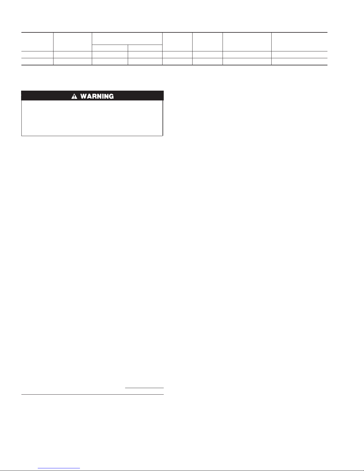
Table 7—Electrical Data
MAX
UNIT
AMPS
MIN
WIRE
GAGE
MAX WIRE
LENGTH (FT)†
1. Inspection for any deterioration in chimney or vent. If deterioration is discovered, chimney must be repaired or vent must
FIRE HAZARD or UNIT MAY NOT OPERATE
Failure to follow this caution may result in property damage
or intermittent unit operation.
Return-air grilles and warm air registers MUST NOT be
obstructed.
be replaced.
2. Inspection to ascertain that vent system is clear and free of
obstructions. Any blockage must be cleared before installing
furnace.
3. Cleaning chimney or vent if previously used for venting a
The proper sizing of warm air ducts is necessary to ensure
satisfactory furnace operation. Duct work should be in accordance
with the latest editions of NFPA-90A (Installation of Air Conditioning and Ventilating Systems) and NFPA-90B (Warm Air
Heating and Air Conditioning Systems) or Canadian equivalent.
The supply duct work should be attached to flanged front opening
provided at discharge end of furnace. The return-air duct work
should be attached to flanged rear opening of furnace. See Fig. 2
for dimensions of these openings.
NOTE: The back (blower access opening) should not be used for
return air.
The following recommendations should be followed when installing duct work:
1. Install locking-type dampers in all branches of individual
ducts to balance out system. Dampers should be adjusted to
impose proper static at outlet of furnace.
2. A flexible duct connector of noncombustible material should
be installed at unit on both supply- and return-air systems. In
applications where extremely quiet operation is necessary, the
first 10 ft (if possible) of supply and return ducts should be
internally lined with acoustical material.
3. In cases where return-air grille is located close to fan inlet,
there should be at least one 90° air turn between fan inlet and
grille. Further reduction in sound level can be accomplished
by installing acoustical air turning vanes or lining duct as
described in item 2 above.
4. When a single air grille is used, duct between grille and
furnace must be the same size as return opening in furnace.
Step 4—Venting
Venting of furnace should be to the outside and in accordance with
local codes or requirements of local utility.
OIL-FIRED APPLIANCES SHALL BE CONNECTED TO
FLUES HAVING SUFFICIENT DRAFT AT ALL TIMES TO
ENSURE SAFE AND PROPER OPERATION OF APPLIANCE.
For additional venting information, refer to ANSI/NFPA 211
Chimney, Fireplaces, Vents, and Solid Fuel Burning Appliances
and/or CSA B139 Installation Code.
This furnace is certified for use with Type ″L″ vent (maximum flue
gas temperature 575°F).
VENT SYSTEM INSPECTION
Before furnace is installed, it is highly recommended that any
existing vent system be completely inspected.
For any chimney or vent, this should include the following:
solid fuel burning appliance or fireplace.
4. Confirming that all unused chimney or vent connections are
properly sealed.
5. Verification that chimney is properly lined and sized per the
applicable codes. (Refer to list of codes in Safety Considerations section.)
MASONRY CHIMNEYS
This furnace can be vented into an existing masonry chimney. This
furnace must not be vented into a chimney servicing a solid fuel
burning appliance. Before venting furnace into a chimney, the
chimney MUST be checked for deterioration and repaired if
necessary. The chimney must be properly lined and sized per local
or national codes.
If furnace is vented into a common chimney, the chimney must be
of sufficient area to accommodate the total flue products of all
appliances vented into chimney.
The following requirements are provided for a safe venting
system:
1. Be sure that chimney flue is clear of any dirt or debris.
2. Be sure that chimney is not servicing an open fireplace.
3. Never reduce pipe size below the outlet size of furnace. (See
Fig. 2.)
4. All pipe should be supported using proper clamps and/or
straps. These supports should be at least every 4 ft.
5. All horizontal runs of pipe should have at least 1/4 in. per ft of
upward slope.
6. All runs of pipe should be as short as possible with as few
turns as possible.
7. Seams should be tightly joined and checked for leaks.
8. The flue pipe must not extend into chimney but be flush with
inside wall.
9. The chimney must extend 3 ft above highest point where it
passes through the roof of a building and at least 2 ft higher
than any portion of a building within a horizontal distance of
10 ft. It shall also be extended at least 5 ft above highest
connected equipment flue collar.
10. Check local codes for any variance.
FACTORY-BUILT CHIMNEYS
Listed factory-built chimneys may be used. Refer to chimney
manufacturer’s instructions for proper installation.
6
MAX FUSE OR
CKT BKR AMPS‡
Page 7

Step 5—Oil Burner
This furnace is supplied with a high-pressure atomizing retention
head-type burner (for use with grade 1 or 2 Fuel Oil). The Riello
oil burner operates with a prepurge period of 10 sec and a safety
timing of 5 sec. The burner flange is factory installed for an
insertion length of 3-3/4-in. The oil pump is set to operate on a
single line system. To operate on a two-line system the by-pass
plug must be installed.
Step 6—Oil Connections
UNIT DAMAGE HAZARD
Failure to follow this caution may result in unit component
damage.
This burner is shipped with the oil pump set to operate on a
single line system. To operate on a two-line system the
by-pass plug must be installed. Do not operate a single line
system with the by-pass plug installed. Operating a single line
system with the by-pass plug installed will result in damage to
the pump shaft seal. Pump pressure must be set at time of
burner start-up. A pressure gauge is attached to the PRES-
SURE PORT for pressure readings. Two PIPE CONNECTORS are supplied with the burner for connection lines to
burner pipe connectors. All pump port threads are British
Parallel Thread design. Direct connection of NPT threads to
the pump will damage the pump body. Riello manometers
and vacuum gauges do not require any adapters, and can be
safely connected to the pump ports. An NPT (metric) adapter
must be used when connecting other gauge models.
Complete instructions for installing fuel oil piping can be found in
oil burner Installation Instructions included with furnace.
Oil line entry holes are provided in side panels. Two holes are
provided in each location so that a 2-pipe system may be used if
desired.
An oil filter should be used with all oil burners and should be
installed as close to burner as possible.
Step 7—Barometric Draft Control
The barometric draft control shipped with furnace MUST be used
with furnace to ensure proper operation. Instructions for installing
control are packed with control.
Step 8—Electrical Connections
ELECTRICAL SHOCK AND FIRE HAZARD
Failure to follow this warning could result in serious injury,
death, or property damage.
The unit cabinet must have an uninterrupted or unbroken
electrical ground to minimize personal injury if an electrical
fault should occur. A green ground screw is provided in
control box for this connection.
115V WIRING
Before proceeding with electrical connections, make certain that
voltage, frequency, and phase correspond to that specified on unit
rating plate. Also, check to be sure that service provided by utility
is sufficient to handle load imposed by this equipment. Refer to
rating plate or Table 7 for equipment electrical specifications.
Make all electrical connections in accordance with National
Electrical Code (NEC) ANSI/NFPA 70-2001 and any local codes
or ordinances that might apply. For Canadian installations, all
electrical connections must be made in accordance with Canadian
Electrical Code CSA C22.1 or subauthorities having jurisdiction.
FIRE HAZARD
Failure to follow this warning could result in serious injury,
death, or property damage.
Do not connect aluminum wire between disconnect switch
and furnace. Use only copper wire.
The control system depends on correct polarity of power supply.
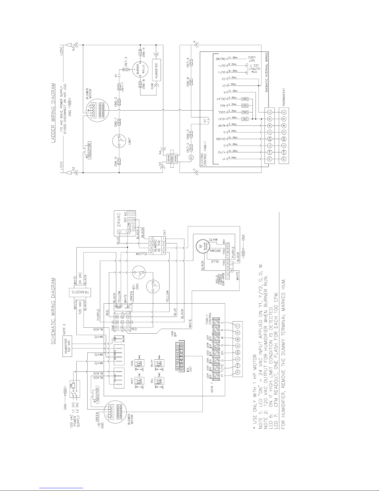
Connect HOT wire (H) and NEUTRAL wire (N) as shown in Fig.
4.
A separate line voltage supply MUST be used with a fused
disconnect switch or circuit breaker between main power panel
and unit. (See Fig. 4.)
Metallic conduit (where required/used) may terminate at side panel
of unit. It is not necessary to extend conduit inside unit from side
panel to control box.
When replacing any original furnace wiring, use only 105°C No.
14 AWG copper wire.
24–V WIRING
→
Instructions for wiring thermostat (field supplied) are packed in
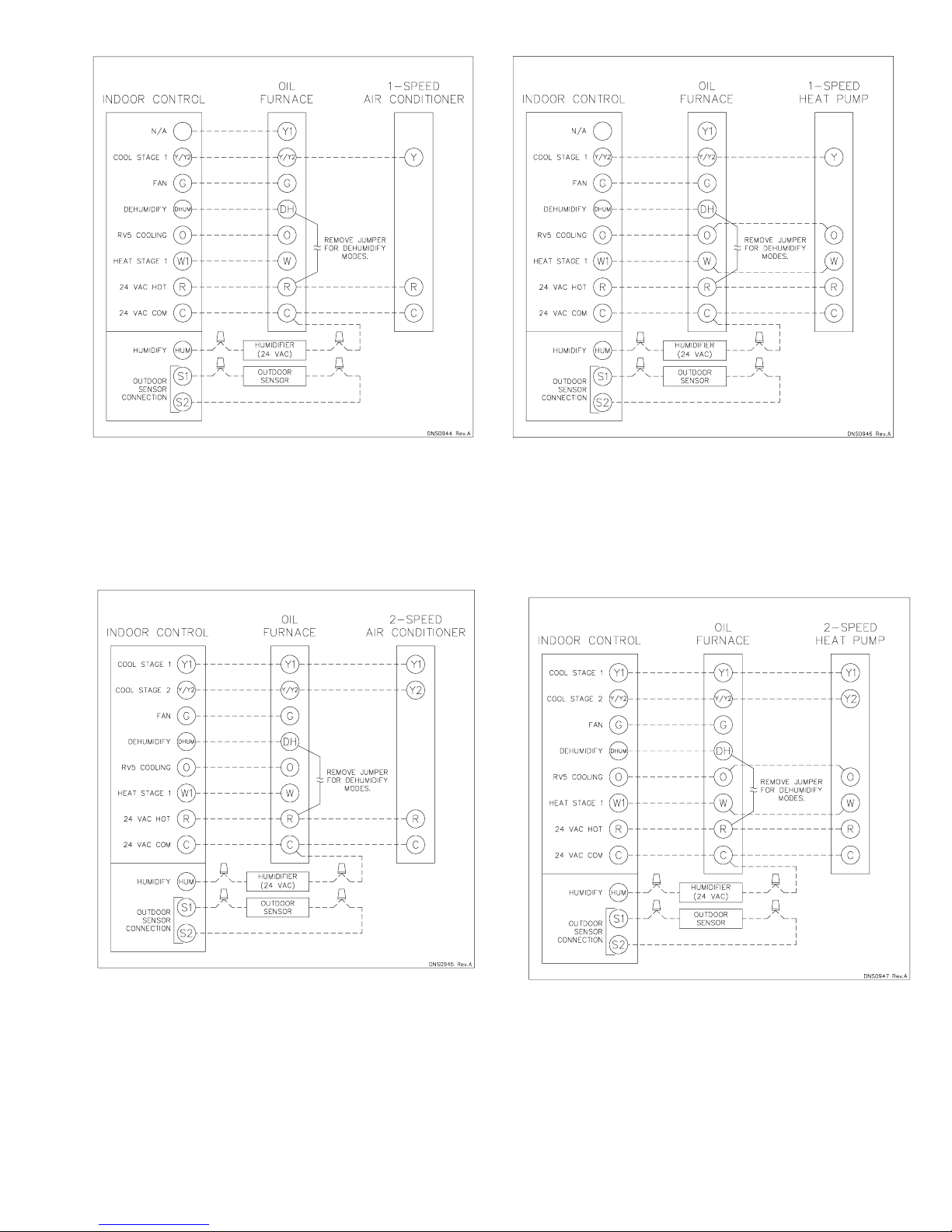
thermostat box. Make thermostat connections as shown in Fig. 5 to
8 at 24-v terminal board on electronic control board. Thermostat
wire connections at R and W are the minimum required for oil
heating operation.
ACCESSORY INSTALLATION
1. General
When installing optional accessories to this appliance, follow
manufacturer’s Installation Instructions included with accessory. Other than wiring for thermostat, wire with a minimum
of type ″T″ insulation (63°F rise) must be used for accessories.
→
2. Auxiliary Terminals
The HUM 120 VAC terminals on the electronic control board
are tied directly to the #8 pin of the 9 pin connector and
provide a 120 VAC signal whenever the burner is energized.
(See Fig. 4.) Supplementary 120 VAC and neutral terminals
can be used for accessory wiring. See Electronic Air Cleaner
and Humidifier sections for further information.
→
3. Electronic Air Cleaner Connections
When using an electronic air cleaner with variable-speed
oil-fired furnaces, use an Airflow Sensor kit. As the air cleaner
is connected to constant 120 VAC power, the airflow sensor
turns on the electronic air cleaner when the furnace blower is
operating.
→
4. Humidifier/Humidistat Connections
To ensure humidifier will operate properly, use HUM output
of Humidistat Control to control humidifier operation. A
24-VAC signal can be connected from the W and C on
terminal block connections on the electronic board or a 120
VAC signal from the ″HUM 120 VAC″ terminal when
primary heating source is used. (See Fig. 4-8.)
→
5. Dehumidify Capability with Standard Humidistat Connection
Latent capabilities for systems using the variable-speed oil-
fired furnaces are better than average systems. If increased
latent capacity is an application requirement, the field wiring
terminal block provides connection terminals for use of a
standard humidistat.
7
Page 8
A04182
Fig. 4—Wiring Diagram
8
Page 9
A04183
Fig. 5—24 VAC Oil Furnace Wiring with 1-Speed
Air Conditioner
A04185
Fig. 7—24 VAC Oil Furnace Wiring with 1-Speed
Heat Pump
Fig. 6—24 VAC Oil Furnace Wiring with 2-Speed
Air Conditioner
A04184
A04186
Fig. 8—24 VAC Oil Furnace Wiring with 2-Speed
Heat Pump
9
Page 10
The variable-speed oil-fired unit will detect the humidistat
contacts opening on increasing humidity and reduce its airflow
to approximately 85 percent of nominal cooling mode airflow.
This reduction will increase the system latent capacity until
the humidity falls to a level which causes the humidistat
contacts to close. When the contacts close, the airflow will
return to 100 percent of the selected cooling airflow. To
activate this mode, remove the Jumper between DH and R of
the electronic board and wire in a standard humidistat.
Step 9—Filters
FIRE, CARBON MONOXIDE AND POISONING
HAZARD
Failure to follow this warning could result in fire, personal
injury, or death.
Never operate unit without a filter or with filter access door
removed.
An internal filter rack is provided as standard equipment with
furnace and is located in blower compartment. A sufficient
clearance should be provided for air filter access. Refer to Table 8
for filter rack flange dimensions for return air duct.
Table 8—Filter Size (In.) and Quantity
UNIT
AIR FILTER
SIZE
105–12 (2)12X20 20X20 20X20
120–20 (2)16X20 22X20 24X20
SIZE
STARTUP, ADJUSTMENT, AND SAFETY CHECKOUT
Step 1—Operational Checkout
Installation of furnace is now complete. Run through the following
checkout and ensure each item has been performed.
1. Correct nozzle size has been selected for desired input rate.
2. Electrical wiring is completed according to Fig. 4.
3. Blower wheel support is removed.
4. Blower access door is secured in place.
5. Valve on oil supply line is open.
6. RESET BUTTON on primary control is pushed down.
7. Flame observation door is closed.
8. Thermostat is set for heating mode and set above room
temperature.
If all of the above items have been performed, set main electrical
switch to ON position and burner should start. When burner starts,
proceed to Combustion Check section.
→
Step 2—Sequence of Operation
Using schematic diagram in Fig. 4 follow the sequence of
operation through the different modes. Read and follow diagram
very carefully.
NOTE: The GE ICM2 + blower motor speeds are infinitely
variable control airflow rate (CFM). The ICM2+ motor ramps to
speed at a controlled rate to reduce start-up noise perception. The
ICM2+ motor ramps down slowly to a stop in the same time as
ramp-up time. ICM2+ ramp-up and ramp-down times are additive
to blower-on and -off delays, respectively. The ICM2+ is 115-v
energized whenever power is available at furnace control, but
operates only when 24-v motor control input(s) are on.
RETURN OPENING
SIZE
SUPPLY OPENING
SIZE
OIL-FIRED HEATING MODE
1. The thermostat closes R to W.
2. Burner motor starts. The burner motor fan pre-purges the
combustion chamber and vent for 10 seconds, establishing the
combustion air pattern. During this time the solenoid valve
holding oil pressure will be approximately 100 psig. Solenoid
valve opens, allowing oil to flow through nozzle. At the same
time, the burner motor’s ignition coil produces spark.
3. Spark ignites oil droplets.
4. Cad cell senses flame and burner continues to fire. Ignition
transformer ceases sparking.
5. After the ″Pre-Run″ ON-delay time, the circulating air blower
starts.
6. The circulating air blower and burner motor remain ON until
the thermostat is satisfied. The solenoid valve remains open
(R40-F)
7. Thermostat is satisfied.
8. The solenoid valve closes and the burner fan motor shuts
down.
9. The furnace blower motor continues operating at 38 percent of
the heating airflow for an additional 3 min.
COOLING MODE
a. Single-Speed Cooling Outdoor Unit (See Fig. 5 for ther-
mostat connections.)
(1.) The thermostat closes R to G-and-Y circuits. The
R-Y/Y2 circuit starts outdoor unit, and R to G-andY/Y2 circuits start the furnace BLWM on cooling
speed.
(2.) When thermostat is satisfied, the R to G-and-Y/Y2
circuits are opened. The outdoor unit stops, and
furnace BLWM continues operating at 50 percent of
the cooling airflow for an additional 180 sec.
b. Two-Speed Cooling Outdoor Unit (see Fig. 17 for thermo-
stat connections.)
(1.) The thermostat closes the R to G-and-Y1 circuits for
low cooling or closes the R to G-and Y1-and-Y/Y2
circuits for high cooling. The R to Y1 circuit operates
the outdoor unit on low-cooling speed. The R to
G-and-Y1 circuit operates the furnace BLWM at
low-cooling airflow 55 percent of single-speed cooling airflow. The R to Y1-and-Y2 circuits operate the
outdoor unit on high-cooling speed, and the R to
G-and-Y/Y2-and-Y1 circuits operate furnace BLWM
at high-cooling airflow.
NOTE: Y1 is found in the furnace and in the outdoor unit. The
furnace control CPU controls BLWM airflow by sensing only
G-and-Y1 for low-cooling airflow and G-and-Y1-and-Y/Y2-for
high-cooling airflow.
(2.) When the thermostat is satisfied, the R to G-and-Y1 or
R to G-and-Y1-andY/Y2 circuits open. The outdoor
unit stops, the furnace blower continues operating at
50 percent of the cooling airflow for an additional 3
min.
CONTINUOUS-BLOWER MODE
a. When R to G circuit is closed by the thermostat, BLWM
operates at 64 percent, 75 percent, or 86 percent of
single-speed cooling airflow; depend on dipswitch setting
(See Tables 13 and 14.)
b. During a call for heat, the BLWM will keep continuous-
blower speed until the end of ″Short run″ delay period.
10
Page 11

After which the BLWM operates at the appropriate oil
heating airflow. The BLWM reverts to continuous blower
airflow after the heating cycle is completed.
c. When thermostat ″calls for low-cooling″, the BLWM keeps
continuous-blower speed until the end of ″Short run″ delay
period. After which the BLWM operates at the appropriate
low cooling airflow. When the thermostat is satisfied, the
BLWM switches to continuous-blower airflow.
d. When the thermostat calls for high cooling, the BLWM
keep continuous-blower speed until the end of ″Short run″
delay period. After which the BLWM operates at the
appropriate high cooling airflow.
e. When R-G circuit is opened, the BLWM stops immedi-
ately.
HEAT PUMP
NOTE: A dual-fuel thermostat is required when variable speed
furnaces are used with heat pumps. See dual-fuel thermostat
Installation Instructions for interface connections. The interface
prevents simultaneous operation of both furnace and heat pump,
and prevents direct transition from heat pump to furnace operation.
a. Single-Speed Heat Pump Cooling
(1.) The thermostats close the R to Y/Y2-and-G-and-O
circuits to operate the Furnace BLWM at cooling
airflow. The Y/Y2 input to the furnace control is
necessary to provide adequate cooling airflow.
(2.) When thermostat is satisfied, furnace BLWM contin-
ues operating at 50 percent of the cooling airflow for
an additional 3 min
b. Two-Speed Heat Pump Cooling
(1.) The thermostat closes the R to G-and-Y1-and-O
circuits to operate the furnace BLWM at low-cool
airflow. The thermostat R to G-and-Y/Y2-and-Y1and-O circuits operates the furnace BLWM at highcool airflow.
NOTE: The furnace control CPU controls blower airflow by
sensing G, Y1, and O for low-cool airflow and G, Y1, Y/Y2, and
O for 2-speed high-cool airflow.
(2.) When the thermostat is satisfied, the furnace BLWM
continues operating at 50 percent of the additional 3
min.
c. Single-Speed Heat Pump Heating
(1.) The thermostats close R to G-and-Y/Y2 circuits to
operate the furnace BLWM at heat pump heating
airflow. Heating airflow is the same as cooling airflow.
(2.) When thermostat is satisfied, the furnace BLWM
continues operating at 50 percent of the heat pump
heating airflow for an additional 3 min.
d. Two-Speed Heat Pump Heating
(1.) The thermostat closes the R to Y1-and-G circuits for
low heat and operates the furnace BLWM at heat
pump low-heat airflow. Closing R-Y/Y2, Y1 and G
circuit to furnace provides BLWM heat pump highheat airflow.
NOTE: The furnace control CPU controls BLWM airflow by
sensing G and Y1 for heat pump low-heat airflow, and G, Y1, and
Y/Y2 for heat pump high-heat airflow.
(2.) When the thermostat is satisfied, the furnace BLWM
continues operating at 50 percent heating airflow for
an additional 3 min.
(3.) Opening only R-Y/Y2 circuit switches BLWM to heat
pump low-heat airflow.
DEFROST
When furnace controls R to W/W1-and-Y/Y2 circuits are closed,
furnace control CPU starts and burner and BLWM operation is at
oil heating airflow during defrost.
Step 3—Combustion Check
In order to obtain optimum performance from oil burner, the
following setup procedures must be followed:
1. A test kit to measure smoke, stack draft, over-fire draft, CO
oil pump pressure, and stack temperatures MUST be used in
order to obtain proper air band setting. Although all of the
above measurements are required for optimum setup and
efficiency data, the most important readings that must be taken
are smoke number, over-fire draft, stack draft, and pump
pressure.
2. The proper smoke number has been established by engineering tests to be between 0 and 1. This degree of smoke emission
is commonly referred to as a ″trace″ of smoke. It is recommended to use a Bacharach true spot smoke test set or
equivalent.
3. In order to ensure proper draft through furnace, a barometric
draft regulator (supplied with furnace) must be installed.
In order for this device to function properly, barometric
damper must be mounted with hinge pins horizontal and face
of damper vertical. (See instructions included with damper.)
The draft regulator should be adjusted after furnace has been
firing for at least 5 minutes, and set between -0.025 and -0.035
in. wc. (See Table 9.)
Table 9—Furnace Draft Conditions
(In. wc)
FURNACE
INPUT
(BTUH)
70,000 –0.025 0.010 0.020 to 0.035
91,000 –0.025 0.020 0.030 to 0.045
105,000 –0.025 0.025 0.035 to 0.050
119,000 –0.025 0.025 0.035 to 0.050
140,000 –0.025 0.025 0.035 to 0.050
154,000 –0.025 0.025 0.035 to 0.050
4. The over-fire draft, which is taken through observation door
(located in center line above burner in front panel of furnace),
is a measurement necessary to determine if there is a blockage
between oil burner and flue outlet.
There should be a total pressure drop of between 0.020 and
0.05 in. wc through furnace as shown in Table 9. The over-fire
draft must be set within the range shown in Table 9. A reading
outside the range shown in Table 9 (for example +0.1 in. wc)
would indicate that furnace is in an extremely high-pressure
condition in primary section. This condition may be caused by
any of the following problems:
a. Excessive combustion air due to air shutter being too wide
open.
b. A lack of flue draft (chimney effect) or some other
blockage, such as soot, in secondary section of heat
exchanger.
c. Use of an oversized nozzle input.
d. Pump pressure over the values listed in Table 10.
FLUE
DRAFT
MINIMUM
OVER-FIRE
DRAFT
MAXIMUM
TOTAL RESTRICTION
THROUGH
HEAT EXCHANGER
,
2
11
Page 12
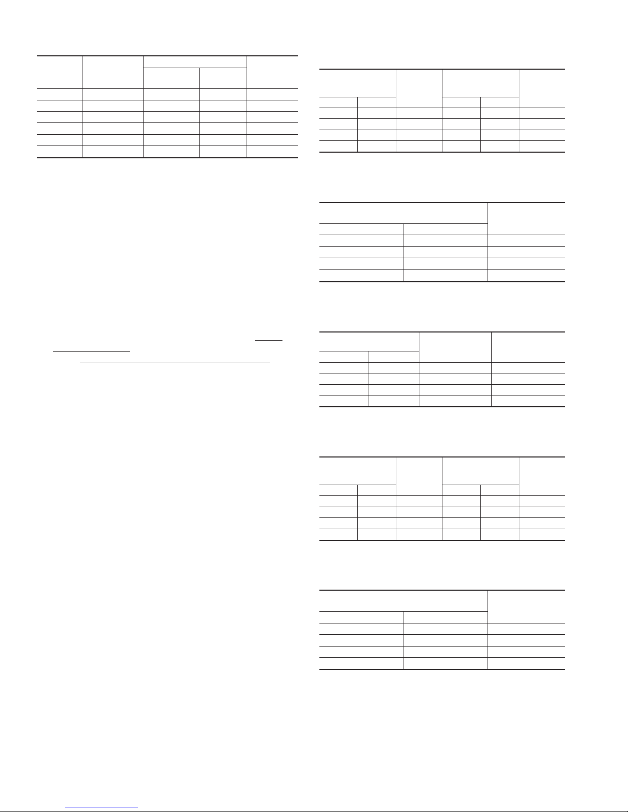
Table 10—Burner Input And Nozzle Size
FURNACE
INPUT
(BTUH)
70,000 0.50 F3 0.40 - 70A 160
91,000 0.65 F3 0.50 - 70W 170
105,000 0.75 F3 0.65 - 70W 135
119,000 0.85 F5 0.75 - 70B 130
140,000 1.00 F5 0.85 - 70W 140
154,000 1.10 F5 1.00 - 70W 125
* For rating puropses only.
FIRING
RATE
GAL/HR (US)*
5. The CO2and stack temperature instruments enable you to
obtain data required to determine thermal efficiency of furnace.
6. An oil filter should be installed as close to burner as possible
with ALL oil burners and is essential on lower firing rate
burners. We recommend the use of a low pressure drop oil
filter such as the General Filter, Inc. model #1A-25A or
equivalent.
7. The oil pressure regulator is factory set to give oil pressure of
135 psig for the model having 105,000 BTUH input and 130
psig for the model having 119,000 BTUH input. The firing
rate noted on nameplate may be obtained using the nozzles
and pump pressures indicated in Table 10. The proper oil
burner turbulator setting for all the firing rates is 0 (zero).
8. On a new installation, air entrapped in oil line leading from
tank to nozzle must be thoroughly purged in order to prevent
excessive after drip. The oil pump is provided with a special
fitting which allows purging of any air between tank and oil
pump. The proper procedure for performing this operation is
as follows:
a. Place a piece of clear plastic 1/4 in. diameter tubing over
purge fitting on oil pump.
b. Start oil burner, then open purge fitting and allow burner to
run until purge tube is completely free of air bubbles.
c. Tighten purge fitting. Allow oil to run to nozzle and fire
burner.
d. If purging takes longer than 15 sec and no flame has been
established, burner stops. Push reset button on front of
primary control to restart burner.
e. For detailed information on operation of primary control,
refer to instructions included with furnace.
After all the setup procedures mentioned above have been completed, the burner should be allowed to operate and an inspection
mirror should be used to observe the flame pattern at tip of nozzle.
Any irregularities such as burning to 1 side or pulsating flame
patterns should be corrected by changing nozzle.
Step 4—Fan Adjustment Check
This furnace is equipped with a variable speed motor. The blower
→
is factory set to deliver the required airflow for 0.75GAL/HR(US)
INPUT and 3.0 tons air conditioning for the 58VLR105 (See
Tables 11A, 11B, and 11C). The blower is factory set to deliver the
required airflow for 0.85GAL/HR (US) INPUT and 5 tons air
conditioning for the 58VLR120 (See Tables 12A, 12B, and 12C).
The blower is field adjustable to deliver the required airflow for
other capacities.
RIELLO OIL BURNER
No. 40 Series
Model
Delavan
Nozzle
PUMP
PRESSURE
(PSIG)
Table 11a—58VLR105 Size Dip Switch Adjustment
for Oil Heating Mode
SW1-HEAT
DIP SWITCH
POSITION
1 212
OFF OFF 0.75 OFF OFF 0.75
ON OFF 0.65 ON OFF 0.65
OFF ON 0.5 OFF ON 0.5
ON ON N/A ON ON N/A
INPUT
USGPH
SW4-DELAY
DIP SWITCH
POSITION
INPUT
USGPH
Table 11b—58VLR105 Size Dip Switch
Adjustments for Heat Pump and Cooling Mode
SW2-COOL
DIP SWITCH POSITION
1 2
OFF OFF 3.0
ON OFF 2.5
OFF ON 2.0
ON ON 1.5
A/C SIZE
(TONS)
Table 11c—58VLR105 Size Dip Switch CFM
Adjustments in All Modes
SW2-ADJUST
DIP SWITCH POSITION
1 2
OFF OFF 0 0
ON OFF + 13 + 10
OFF ON - 15 - 10
ON ON N/A 0
HEATING CFM %
INCREASE OR
DECREASE
COOLING CFM %
INCREASE OR
DECREASE
Table 12a—58VLR120 Dip Switch Adjustment for
Oil Heating Mode
SW1-HEAT
DIP SWITCH
POSITION
1 212
OFF OFF 0.85 OFF OFF 0.85
ON OFF 1.00 ON OFF 1.00
OFF ON 1.10 OFF ON 1.10
ON ON N/A ON ON N/A
INPUT
USGPH
SW4-DELAY
DIP SWITCH
POSITION
INPUT
USGPH
Table 12b—58VLR120 Size Dip Switch
Adjustments for Heat Pump and Cooling Mode
SW2-COOL
DIP SWITCH POSITION
1 2
OFF OFF 5.0
ON OFF 4.0
OFF ON 3.5
ON ON 3.0
A/C SIZE
(TONS)
12
Page 13
120 VA C
NEUTRALS
HUM
P2
SW1
1
OFF OFF
OFF
OFFONON
ON
ON
ON
OFF
SW3
1
OFF OFF
OFF
OFFONON
ON
ON
ON
OFF
SW2
1
OFF OFF
OFF
OFFONON
ON
ON
ON
OFF
SW4
1
OFF OFF
OFF
OFFONON
ON
ON
ON
OFF
P1
R14
R12
D18
2
2
LED7
GRN
GRN
COOL
DELAY
D17
A
B
C
D
A
B
C
D
JW5
D6
D7
SW2
D8
D9
D10
D11
D12
D14
SW4
R2
JW7
D19
GRN
JW6
R1
JW3
GRN
HEAT
2
A
B
C
D
SW1
ADJ
2
A
B
C
D
SW3
LED4 LED3 LED5 LED7 LED8 LED1
GRN
JW4
GRN
120 VAC
JW1
R3
D20
GRN
R23
R13
D16
R21
D21
LED
RED
24 VA C
C
F1
U1
01
R20
C2
U2
D13
D02
D04
D1
D3
JW2
D15
KJ
R22
MO V1
C1
HSC 1
1168-83-1
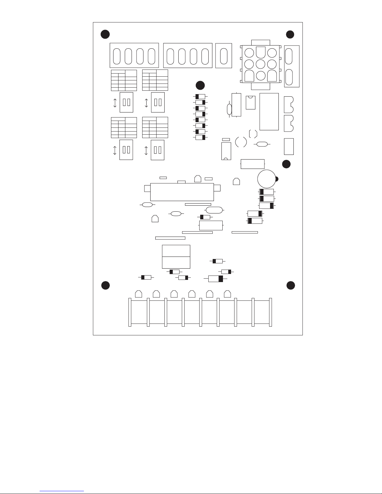
NOTES
1. The Red LED to the right of P-1 will illuminate whenever the limit switch is open.
2. The Green LED below the left end of P-1 will flash when the blower motor is operating.
The LED will flash one time for each 100 RPM.
3. The Green LEDs above Y1, Y/Y2, G, O, and W will illuminate whenever there is a 24V
input from the thermostat.
4. The Green LED above DH will illuminate whenever there is not a 24VAC input applied.
Y
Y/Y2 G DH O W R C
Fig. 9—Control Board
13
P3
A04194
Page 14
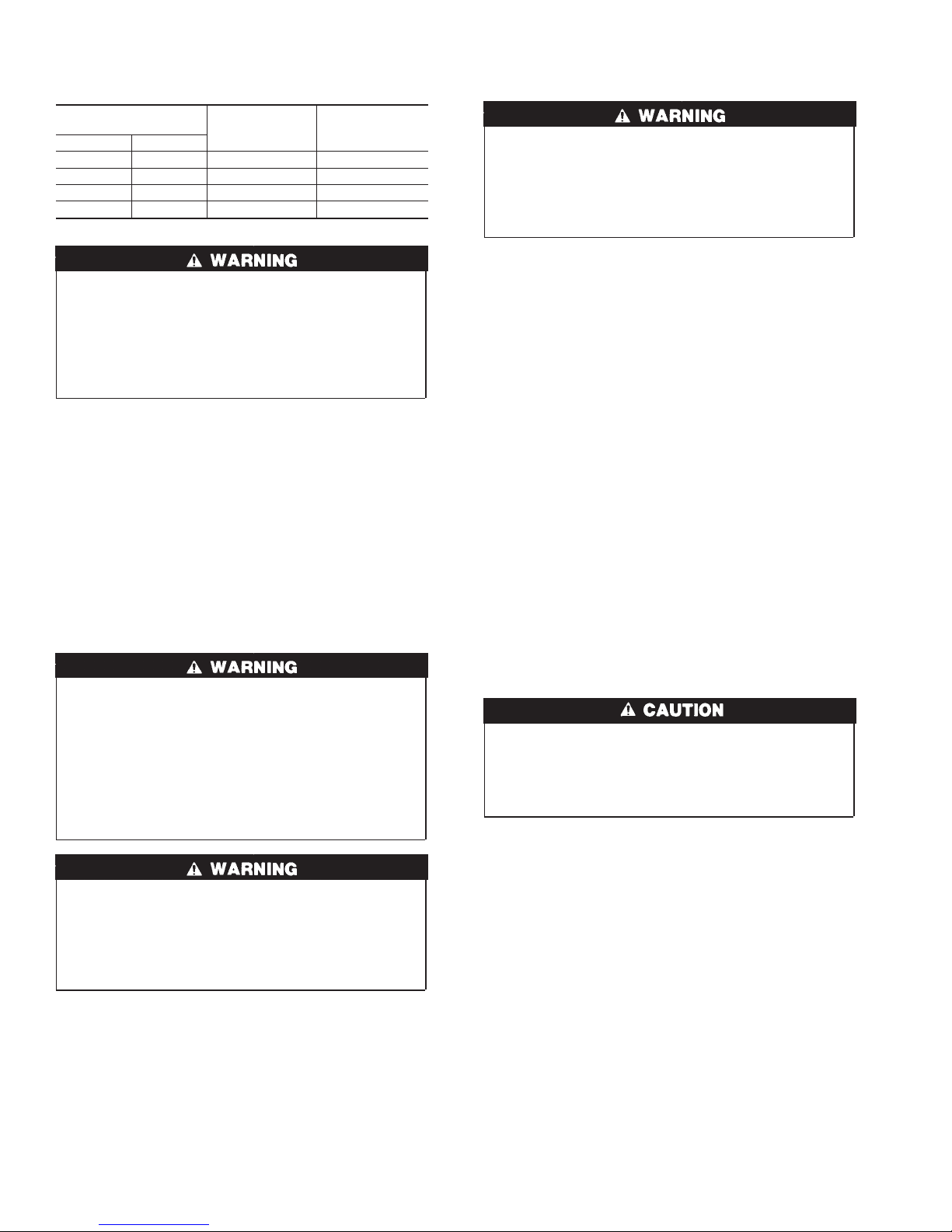
Table 12c—58VLR120 Size Dip Switch CFM
Adjustments in All Modes
SW2-ADJUST
DIP SWITCH POSITION
1 2
OFF OFF 0 0
ON OFF + 13 + 10
OFF ON - 15 - 10
ON ON N/A 0
FIRE HAZARD AND UNIT RELIABILITY
Failure to follow this warning could result in property
damage, personal injury or death.
When operating furnace in heating mode, static pressure and
temperature rise (supply-air temperature minus return-air
temperature) must be within those limits specified on rating
label.
Step 5—Limit Control Check
After furnace has been in operation for at least 15 minutes, restrict
return-air supply by blocking filters or closing return registers and
allow furnace to shut down on high limit. The burner should shut
off, and main blower should continue to run.
Step 6—For Year-Round Air Conditioning
This furnace is designed for use in conjunction with cooling
equipment to provide year-round air conditioning. The blower has
been sized for both heating and cooling, however, fan motor
setting may need to be changed to obtain necessary cooling
airflow.
CARE AND MAINTENANCE
ELECTRICAL SHOCK, FIRE OR EXPLOSION
HAZARD
Failure to follow this warning could result in possible damage
to this equipment, serious personal injury, or death.
The ability to properly perform maintenance on this equipment requires certain expertise, mechanical skills, tools, and
equipment. If you do not possess these, do not attempt to
perform any maintenance on this equipment other than those
procedures recommended in the User’s Manual.
ELECTRICAL SHOCK HAZARD
Failure to comply with this warning could cause electrical
shock resulting in personal injury or death.
Before performing any service functions, unless operations
specifically require power to be on, make sure all utilities are
turned off upstream of appliance.
Step 1—General
In order to keep this furnace in good operating condition and to
maintain its warranty, the furnace MUST be serviced on an annual
basis. This servicing includes a nozzle change, a burner inspection,
a visual check of tube passages through flue outlet and cleanout
ports, and a visual inspection of combustion chamber when burner
is removed.
Depending on above inspection, service could also include a
cleaning and vacuuming of heat exchanger tubes and possibly the
heat exchanger drum section.
HEATING CFM %
INCREASE OR
DECREASE
COOLING CFM %
INCREASE OR
DECREASE
Removal of any heat exchanger components which are sealed by
gaskets requires replacement of gasket.
CARBON MONOXIDE POISONING HAZARD
Failure to replace any heat exchanger gaskets with new
gaskets when any heat exchanger plates or covers are removed could lead to heat exchanger leakage, sooting, and/or
a hazardous condition capable of causing personal injury or
death.
This furnace should never be operated without an air filter.
Disposable filters should be replaced at least once a year. If
equipped to provide cooling, filters should be replaced a minimum
of twice a year. Permanent filters should be cleaned at least twice
a year.
ALWAYS KEEP MAIN OIL VALVE TURNED OFF IF
BURNER IS SHUT DOWN FOR AN EXTENDED PERIOD OF
TIME.
Step 2—Oil Burner
For optimum performance, oil burner nozzle should be replaced
once a year. Contact your service technician if you are unsure of
this procedure.
The procedure for nozzle installation and/or replacement is outlined in oil burner instruction manual which came with furnace.
After replacement of nozzle, burner should be adjusted in accordance with Combustion Check section of this instruction.
Step 3—Heat Exchanger and Flue Pipe
Ordinarily, it is not necessary to clean heat exchanger or flue pipe
every year, but it is necessary to have your service technician
check unit before each heating season to determine whether
cleaning or replacement of parts is required.
If cleaning is necessary, the following steps should be performed:
1. Turn off all oil and electrical supplies upstream of furnace.
BURN HAZARD
Failure to follow this caution may result in minor personal
injury.
If furnace has been in operation, some surfaces may be hot.
Allow time for unit to cool down.
2. Disconnect flue pipe.
3. Remove flue collar panel located in rear part of furnace.
4. Remove flue silencer from secondary heat exchanger.
5. Disconnect oil line and remove oil burner from furnace.
6. Clean primary and secondary heat exchangers with a stiff
brush and vacuum cleaner.
7. Before reassembly, heat exchanger/combustion chamber
should be inspected to determine if replacement is required.
8. After cleaning, replace flue silencer, flue collar, and oil
burner.
9. Readjust burner for proper operation.
Step 4—Blower Removal
To remove blower from furnace:
1. Turn off all oil and electrical supplies upstream of furnace.
2. Remove blower access door.
3. Remove air filters.
4. Remove blower retaining wing nuts.
14
Page 15
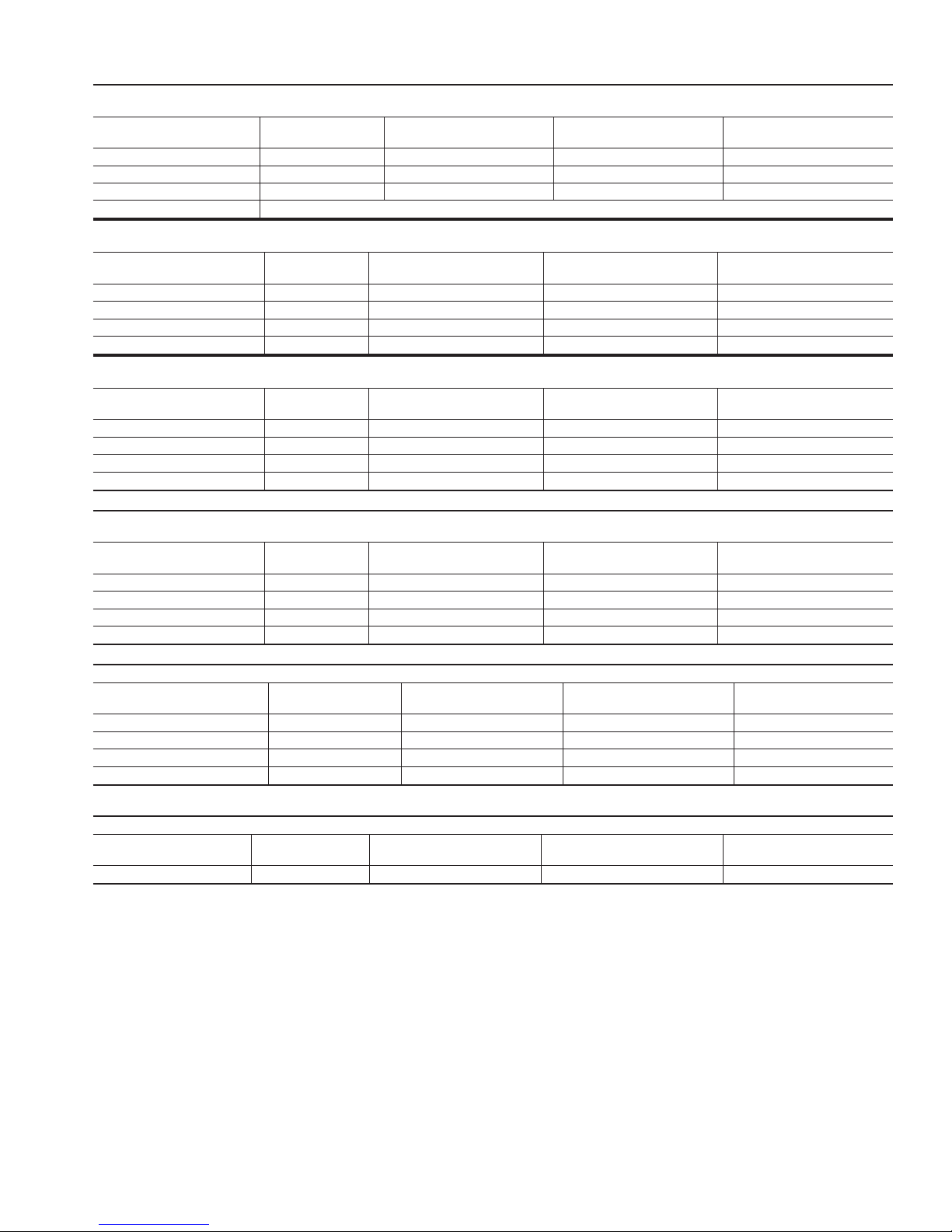
→ Table 13—58VLR105 Size Airflow Data (CFM)
OIL HEATING MODE
24 VAC INPUT (R) ON W ONLY
SW1-HEAT
Dip Switch Position
A (1=OFF, 2=OFF) 0.75 1260 1425 1070
B (1=ON, 2=OFF) 0.65 1050 1190 895
C (1=OFF, 2=ON) 0.5 850 960 725
D (1=ON, 2=ON) Same Value then A Dip Switch Position
SW2-COOL
Dip Switch Position
A (1=OFF, 2=OFF) 3.0 785 905 670
B (1=ON, 2=OFF) 2.5 655 755 560
C (1=OFF, 2=ON) 2.0 525 605 445
D (1=ON, 2=ON) 1.5 395 455 335
SW2-COOL
Dip Switch Position
A (1=OFF, 2=OFF) 3.0 1050 1155 945
B (1=ON, 2=OFF) 2.5 875 965 790
C (1=OFF, 2=ON) 2.0 700 770 630
D (1=ON, 2=ON) 1.5 525 580 475
NOTE: In cooling-Dehumidification mode, with no 24 VAC input to DH, the CFM is reduced by 15%
SW2-COOL
Dip Switch Position
A (1=OFF, 2=OFF) 3.0 580 635 520
B (1=ON, 2=OFF) 2.5 480 530 435
C (1=OFF, 2=ON) 2.0 385 425 345
D (1=ON, 2=ON) 1.5 290 320 260
NOTE: In Cooling-Dehumidification mode, with no 24 VAC input to DH, the CFM is reduced by 15%
SW4-DELAY
Dip Switch Position
A (1=OFF, 2=OFF) 0.75 13% - 45 sec 19% - 30 sec 38% - 3 min.
B (1=ON, 2=OFF) 0.65 13% - 45 sec 19% - 60 sec 38% - 3 min.
C (1=OFF, 2=ON) 0.5 13% - 60 sec 13% - 60 sec 38% - 3 min.
D (1=ON, 2=ON) All 13% - 30 sec 100% - 0 sec 100% - 2 min.
Short Run is the time before the blower start at normal speed, with very low CFM, to minimize cool draft in the air distribution system.
Off Delay is the time required to cool down the heat exchanger, with low CFM, to minimize cool draft in the air distribution system.
No Adjustment
Required
- All 13% - 30 sec 75% - 2.5 min. 50% - 3 min.
Short Run is the time before the blower start at normal speed, with lower CFM, to minimize cool draft in the air distribution system.
Off Delay is the time required to cool down the coil (heating mode), with low CFM, to minimize cool draft in the air distribution system.
HEAT INPUT
(USGPH)
A/C Size
(TON)
COOLING OR HEAT PUMP HEATING MODE - SINGLE SPEED OR 2-SPEED HIGH
24 VAC INPUT (R) TO G, Y/Y2 AND O (FOR COOLING)
A/C Size
(TON)
COOLING MODE OR HEAT PUMP HEATING MODE - 2-SPEED LOW
24 VAC INPUT (R) TO G, Y1 AND O (FOR COOLING)
A/C Size
(TON)
DELAY PROFILE FOR OIL HEATING MODE
HEAT INPUT
(USGPH)
DELAY PROFILE FOR COOLING OR HEAT PUMP HEATING MODE
A/C Size
CFM with SW3-ADJ
Dip Switch A Position
CONTINUOUS FAN
24 VAC INPUT (R) ON G ONLY
CFM with SW3-ADJ
Dip Switch A Position
CFM with SW3-ADJ
Dip Switch A Position
CFM with SW3-ADJ
Dip Switch A Position
Pre-Run On-Delay
CFM Level - Time
Pre-Run On-Delay
Time
CFM with SW3-ADJ
Dip Switch B Position
CFM with SW3-ADJ
Dip Switch B Position
CFM with SW3-ADJ
Dip Switch B Position
CFM with SW3-ADJ
Dip Switch B Position
Short Run On-Delay
CFM Level - Time
Short Run On-Delay
CFM Level - Time
CFM with SW3-ADJ
Dip Switch C Position
CFM with SW3-ADJ
Dip Switch C Position
CFM with SW3-ADJ
Dip Switch C Position
CFM with SW3-ADJ
Dip Switch C Position
CFM Level - Time
CFM Level - Time
Off-Delay
Off-Delay
5. Slide blower on rails toward rear of unit.
6. Reverse items 1 through 5 to reinstall blower. Refer to wiring
diagram (See Fig. 4) of these instructions or diagram located
on inside of blower door to properly rewire unit.
15
Page 16
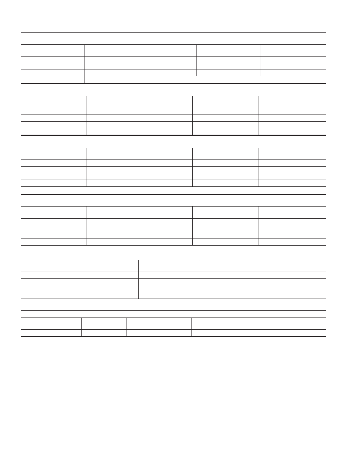
→ Table 14—58VLR120 Size Airflow Data (CFM)
OIL HEATING MODE
24 VAC INPUT (R) ON W ONLY
SW1-HEAT
Dip Switch Position
A (1=OFF, 2=OFF) 0.85 1450 1640 1235
B (1=ON, 2=OFF) 1.00 1700 1920 1445
C (1=OFF, 2=ON) 1.10 1850 2090 1575
D (1=ON, 2=ON) Same Value then A Dip Switch Position
SW2-COOL
Dip Switch Position
A (1=OFF, 2=OFF) 5.0 1315 1510 1115
B (1=ON, 2=OFF) 4.0 1050 1210 895
C (1=OFF, 2=ON) 3.5 920 1055 780
D (1=ON, 2=ON) 3.0 790 905 670
SW2-COOL
Dip Switch Position
A (1=OFF, 2=OFF) 5.0 1750 1925 1575
B (1=ON, 2=OFF) 4.0 1400 1540 1260
C (1=OFF, 2=ON) 3.5 1225 1350 1105
D (1=ON, 2=ON) 3.0 1050 1155 945
NOTE: In cooling-Dehumidification mode, with no 24 VAC input to DH, the CFM is reduced by 15%
SW2-COOL
Dip Switch Position
A (1=OFF, 2=OFF) 5.0 965 1060 865
B (1=ON, 2=OFF) 4.0 770 845 695
C (1=OFF, 2=ON) 3.5 675 740 605
D (1=ON, 2=ON) 3.0 580 635 520
NOTE: In Cooling-Dehumidification mode, with no 24 VAC input to DH, the CFM is reduced by 15%
SW4-DELAY
Dip Switch Position
A (1=OFF, 2=OFF) 0.85 13% - 45 sec 44% - 30 sec 38% - 3 min.
B (1=ON, 2=OFF) 1.00 13% - 30 sec 44% - 30 sec 38% - 3 min.
C (1=OFF, 2=ON) 1.10 13% - 30 sec 50% - 30 sec 38% - 3 min.
D (1=ON, 2=ON) All 13% - 30 sec 100% - 0 sec 100% - 2 min.
Short Run is the time before the blower start at normal speed, with very low CFM, to minimize cool draft in the air distribution system.
Off Delay is the time required to cool down the heat exchanger, with low CFM, to minimize cool draft in the air distribution system.
No Adjustment
Required
- All 13% - 30 sec 75% - 2.5 min. 50% - 3 min.
Short Run is the time before the blower start at normal speed, with lower CFM, to minimize cool draft in the air distribution system.
Off Delay is the time required to cool down the coil (heating mode), with low CFM, to minimize cool draft in the air distribution system.
HEAT INPUT
(USGPH)
CFM with SW3-ADJ
Dip Switch A Position
CFM with SW3-ADJ
Dip Switch B Position
CONTINUOUS FAN
24 VAC INPUT (R) ON G ONLY
A/C Size
(TON)
CFM with SW3-ADJ
Dip Switch A Position
CFM with SW3-ADJ
Dip Switch B Position
COOLING OR HEAT PUMP HEATING MODE - SINGLE SPEED OR 2-SPEED HIGH
24 VAC INPUT (R) TO G, Y/Y2 AND O (FOR COOLING)
A/C Size
(TON)
CFM with SW3-ADJ
Dip Switch A Position
CFM with SW3-ADJ
Dip Switch B Position
COOLING MODE OR HEAT PUMP HEATING MODE - 2-SPEED LOW
24 VAC INPUT (R) TO G, Y1 AND O (FOR COOLING)
A/C Size
(TON)
CFM with SW3-ADJ
Dip Switch A Position
CFM with SW3-ADJ
Dip Switch B Position
DELAY PROFILE FOR OIL HEATING MODE
HEAT INPUT
(USGPH)
Pre-Run On-Delay
CFM Level - Time
Short Run On-Delay
CFM Level - Time
DELAY PROFILE FOR COOLING OR HEAT PUMP HEATING MODE
A/C Size
Pre-Run On-Delay
CFM Time
Short Run On-Delay
CFM Level - Time
CFM with SW3-ADJ
Dip Switch C Position
CFM with SW3-ADJ
Dip Switch C Position
CFM with SW3-ADJ
Dip Switch C Position
CFM with SW3-ADJ
Dip Switch C Position
CFM Level - Time
CFM Level - Time
Off-Delay
Off-Delay
16
Page 17

SER VICE TRAINING
Packaged Service Training programs are an excellent way to increase your
knowledge of the equipment discussed in this manual, including:
• Unit Familiarization • Maintenance
• Installation Overview • Operating Sequence
A large selection of product, theory, and skills programs is available, using popular
video-based formats and materials. All include video and/or slides, plus companion
book.
Classroom Service Training plus "hands-on" the products in our labs can mean
increased confidence that really pays dividends in faster troubleshooting, fewer
callbacks. Course descriptions and schedules are in our catalog.
CALL FOR FREE CATALOG 1-800-644-5544
[ ] Packaged Service Training [ ] Classroom Service Training
17
Page 18

18
Page 19

19
Page 20

Copyright 2005 CARRIER Corp. • 7310 W. Morris St. • Indianapolis, IN 46231 58vlr2si
Manufacturer reserves the right to discontinue, or change at any time, specifications or designs without notice and without incurring obligations.
Book 1 4
Tab 6a 8a
PC 101 Catalog No. 535-80171 Printed in U.S.A. Form 58VLR-2SI Pg 20 2-05 Replaces: 58VLR-1SI
 Loading...