

Page 1
HEATING & COOLING
© .
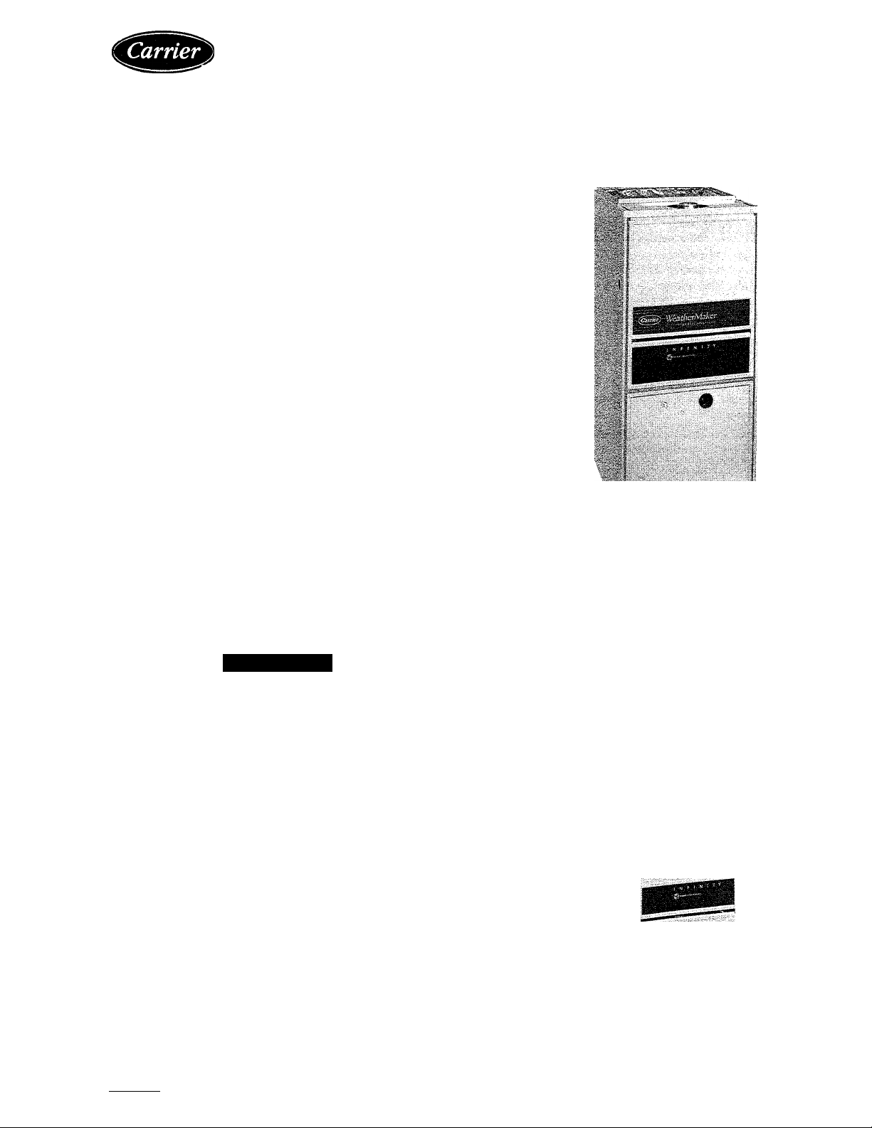
Variable-Speed Gas-Fired Condensing Furnaces
Service and Maintenance Instructions
For Sizes 060-100, Series 100
NOTE: Read the entire instruction manual before starting the
installation.
SAFETY CONSIDERATIONS
Installing and servicing heating equipment can be hazardous
due to gas and electrical components. Only trained and qualified
personnel should install, repair, or service heating equipment.
Untrained personnel can perform basic maintenance functions
such as cleaning and replacing air filters. All other operations must
be performed by trained service personnel. When working on
heating equipment, observe precautions in the literature, tags, and
labels attached to or shipped with the unit and other safety
precautions that may apply.
Follow all safety codes, including NFPA 54/ANSI Z223.1-1988,
National Fuel Gas Code. Wear safety glasses and work gloves.
Have a fire extinguisher available during start-up and adjustment
procedures and service calls.
Recognize safety information. This is the safety-alert symbol ^ .
When you see this symbol on the unit and in instructions or
manuals, be alert to the potential for personal injury.
Understand the signal word —DANGER, WARNING, or CAU
TION. These words are used with the safety-alert symbol. DAN
GER identifies the most serious hazards which will result in severe
personal injury or death. WARNING signifies hazards that could
result in personal injury or death. CAUTION is used to identify
unsafe practices, which would result in minor personal injury or
product and property damage.
Fig. 1—Model 58VUA Upflow Furnace
58VCA
58VUA
A91128
A WARNING
Never store anything on, near, or in contact with the furnace,
such as:
1. Spray or aerosol cans, rags, brooms, dust mops, vacuum
cleaners, or other cleaning tools.
2. Soap powders, bleaches, waxes or other cleaning com
pounds, plastic or plastic containers, gasoline, kerosene,
cigarette lighter fluid, dry cleaning fluids, or other volatile
fluids.
3. Paint thinners and other painting compounds, paper bags or
other paper products.
Failure to follow this warning can cause corrosion of the heat
exchanger, fire, personal injury, or death.
CARE AND MAINTENANCE
For continuing high performance and to minimize possible equip
ment failure, it is essential that maintenance be performed annually
on this equipment. Consult your local dealer for maintenance and
the availability of a maintenance contract.
Fig. 2—Model 58VCA Downflow Furnace
Manufacturer reserves the right to discontinue, or change at any time, specifications or designs without notice and without incurring obiigations.
Book 1 4
Tab 6a 8a
PC 101 Catalog No. 565-997
Printed in U.S.A. Form 58V-1SM
Pg1
О
6-92
A92095
Replaces: 58SXB-1SM
Page 2
A WARNING
The ability to properly perform maintenance on this equip
ment requires certain expertise, mechanical skills, tools, and
equipment. If you do not possess these, do not attempt to
perform any maintenance on this equipment other than those
procedures recommended in the User’s Manual. FAILURE
TO FOLLOW THIS WARNING COULD RESULT IN
POSSIBLE DAMAGE TO THIS EQUIPMENT, SERIOUS
PERSONAL INJURY, OR DEATH.
A WARNING
Turn OFF the gas and electrical supplies to the unit before
performing any maintenance or service. Follow the operating
instructions on the label attached to the furnace. Failure to
follow this warning could result in personal injury.
INSTALLATION
-POSITION
OF FILTERS
The minimum maintenance that should be performed on this
equipment is as follows:
1. Check and clean or replace air filter each month or as required.
2. Check blower motor and wheel for cleanliness and lubrication
each heating and cooling season. Clean and lubricate as
necessary. (See Step 2.)
3. Check electrical connections for tightness, and controls for
proper operation each heating season. Service as necessary.
4. Check for proper condensate drainage; clean as necessary.
5. Check for blockages of combustion-air and vent pipes.
A CAUTION
As with any mechanical equipment, personal injury could
result from sharp metal edges, etc. Be careful when removing
parts.
Step 1—Air Filter Cleaning and Replacement
The air filter arrangement may vary depending on the application.
A CAUTION
Never operate unit without a filter or with filter access door
removed. Failure to follow this warning could result in a fire
or personal injury.
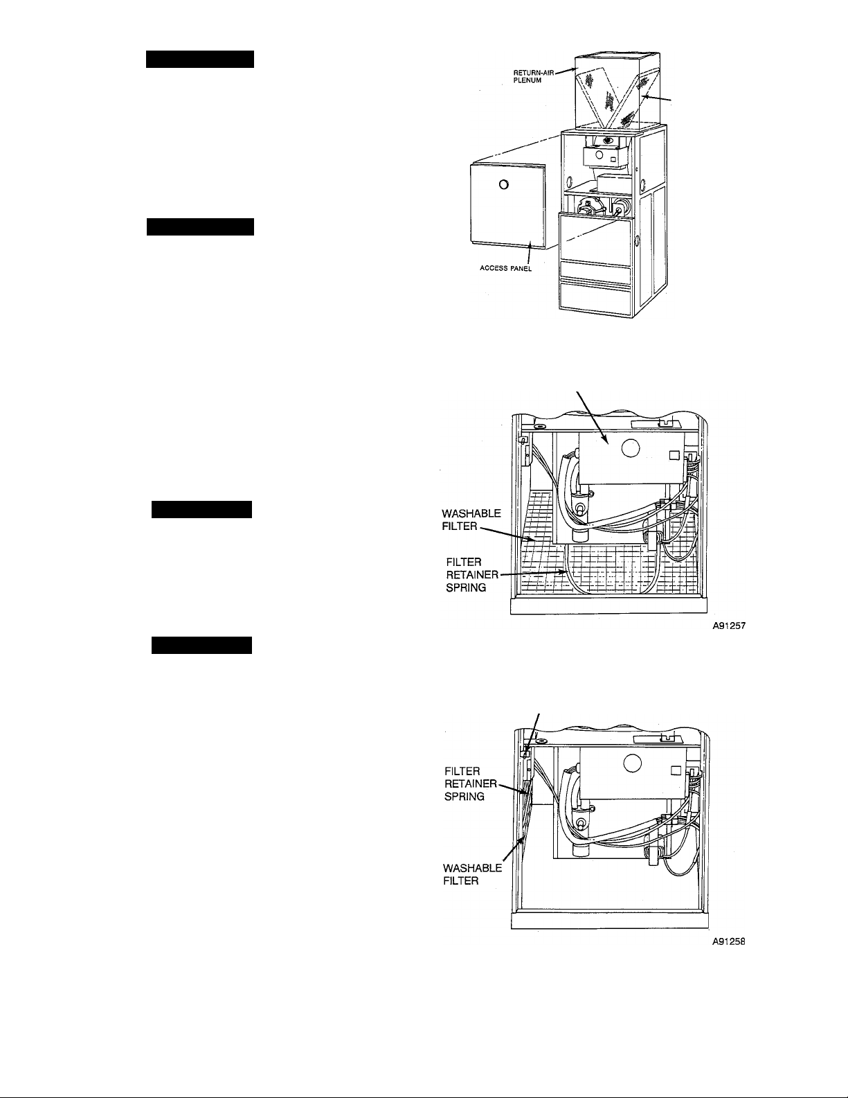
DOWNFLOW FURNACES ONLY - Each furnace accommo
dates 2 filters which are installed in the return-air duct. (See Fig.
3.) To clean or replace the filters, proceed as follows:
1. Turn OFF electrical supply to unit.
2. Remove blower access door.
3. Reaching up behind top plate, tilt filters toward center of
return-air plenum, remove filters, and replace or clean as
needed.
4. Furnaces are equipped with permanent, washable filters. Clean
these filters by spraying cold tap water through filter in
opposite direction of airflow.
5. Rinse filters and let dry. Oiling or coating of filters is not
recommended.
6. Reinstall filters with cross-mesh binding facing blower.
7. Replace access door.
8. Turn ON electrical supply to furnace.
UPFLOW FURNACES ONLY — To clean or replace the air
filter, proceed as follows:
1. Turn OFF electrical supply to unit.
A92117
Fig. 3—Position of Filters in Downflow Furnace
CONTROL
BOX
Fig. 4—Filter Installed for Bottom Inlet
AUX J-BOX
& BLOWER
DOOR SWITCH
Fig. 5—Filter Installed for Side Inlet
2. Remove access doors.
3. Release filter retainer spring from behind flange of furnace
casing. (See Fig. 4 and 5.)
4. Slide filter out.
WA
Page 3
5. Furnaces are equipped with permanent, washable filters. Clean
filter by spraying cold tap water through filter in opposite
direction of airflow.
6. Rinse filter and let dry. Oiling or coating of filter is not
recommended.
7. Place filter in furnace with cross-mesh binding either up or
facing blower.
8. Replace access doors.
9. Turn ON electrical supply to furnace.
Step 2—Blower Motor and Wheel Maintenance
For long life, economy, and high efficiency, clean accumulated dirt
and grease from blower wheel and motor annually.
The following items should be performed by a qualified service
technician:
Some motors have prelubricated, sealed bearings and require no
lubrication. These motors can be identified by the absence of oil
ports on each end of the motor. For motors with oil ports, lubricate
as follows:
Lubricate motor every 5 years if motor is used for intermittent
operation (thermostat FAN switch in AUTO position), or every 2
years if motor is in continuous operation (thermostat FAN switch
in ON position).
Clean and lubricate as follows:
1. Turn OFF electrical supply to unit.
2. Remove access doors.
3. Upflow furnaces only —remove drain trap and control box:
a. Remove control box from bottom side of blower shelf and
position to 1 side.
b. Disconnect 9-circuit connector PL-13 from blower hous
ing.
c. Using backup wrench, disconnect drain pipe at coupling in
blower compartment.
d. Loosen hose clamp and remove 7/8-in. diameter drain hose
from drain trap.
e. Loosen hose clamp and disconnect 5/8-in. diameter drain
hose at bottom of inducer housing located under blower
shelf.
f. Remove screw securing drain trap assembly.
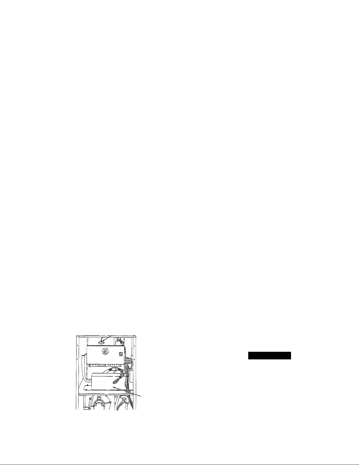
4. Downflow furnaces only — disconnect vent pipe, elbow, and
auxiliary limit switch. (See Fig. 6.)
a. Remove control box from top plate and position to 1 side.
AUXILIARY
UMIT
.SWITCH
c. Disconnect wires from auxiliary limit on blower housing.
d. Remove vent pipe enclosure from top side of blower shelf
and position to 1 side.
e. Loosen hose clamps on outlet elbow and remove elbow.
f. Loosen hose clamp on extension pipe outside of furnace
and remove pipe.
5. Remove screws securing blower assembly to blower shelf and
slide blower assembly out of furnace.
6. Squeeze side tabs of connector PL-13 and pull from blower
housing bracket.
7. Mark blower wheel location on shaft before disassembly to
insure proper reassembly.
8. Loosen setscrew holding blower wheel on motor shaft.
NOTE: Mark blower mounting arms and blower housing so each
arm is positioned at the same hole location during reassembly. This
will insure that oilers point up. ■
9. Remove bolts holding motor mount to blower housing and
slide motor and mounts out of housing.
10. Lubricate motor (when oil ports are provided).
a. Remove dust caps or plugs from oil ports located at each
end of motor. If motor does not have these caps or plugs,
bearings are sealed and need no further lubrication.
b. Use a good grade of SAE 20 nondetergent motor oil and
add 1 teaspoon (5 cc, 3/16 oz, or 16 to 25 drops) in each oil
port. The use of other types or grades of oil will damage the
motor. Excessive oiling can cause premature bearing fail
ures.
c. Allow time for total quantity of oil to be absorbed by each
bearing.
d. After oiling motor, wipe excess oil from motor housing.
e. Replace dust caps or plugs on oil ports.
11. Remove blower wheel from housing:
a. Mark blower wheel orientation and cutoff plate location to
insure proper reassembly.
b. Remove screws securing cutoff plate and remove cutoff
plate from housing.
c. Remove blower wheel from housing.
12. Clean blower wheel and motor using a vacuum with soft brush
attachment. Be careful not to disturb balance weights (clips)
on blower wheel vanes. Do not drop or bend wheel, as balance
will be affected.
13. Reassemble blower by reversing items ll.a. through ll.c.
Ensure wheel is positioned for proper rotation.
14. Reassemble motor and blower by reversing items 6 through 9.
If motor has ground wire, be sure it is reconnected.
Fig. 6—Downflow Furnace Blower Compartment
b. Disconnect 9-circuit connector PL-13 from blower hous
ing.
A92118
A CAUTION
Ensure the motor is properly positioned in the blower
housing. The motor oil ports must be at a minimum of 30°
above the horizontal centerline of the motor after the blower
assembly has been reinstalled in the furnace.
15. Reinstall blower assembly in furnace.
16. Upflow furnaces only — reinstall drain trap and control box:
a. Inspect drain trap and hoses to ensure they are not blocked
or restricted. Reinstall drain trap and hoses. Be sure to
tighten hose clamps.
b. Using backup wrench, attach drain pipe and tighten com
pression coupling.
Page 4

c. Reinstall control box on bottom side of blower shelf.
17. Downflow furnace only — reconnect vent pipe, elbow, and
auxiliary limit switch.
a. Reinstall outlet elbow and extension pipe. Be sure connec
tions are tight and leak proof.
b. Reinstall vent pipe enclosure.
c. Reconnect red wires to auxiliary limit switch.
d. Reinstall control box on top plate.
18. Connect 9-circuit connector PL-13 to blower harness. Note
that connections are polarized for correct assembly — do not
force.
19. Turn ON electrical supply and check for proper rotation and
speed changes between low- and high-heat and cooling.
Operate unit 10 minutes and carefully check for condensate
leaks.
Step 3—Cleaning Heat Exchangers
The following items should be performed by a qualified service
technician:
If it becomes necessary to clean the heat exchanger because of
carbon deposits, soot, etc., proceed as follows:
NOTE: Deposits of soot and carbon indicate a problem exists that
needs to be corrected. Action must be taken to correct the problem.
1. Turn OFF gas and electrical supplies to furnace.
2. Remove control and blower access doors.
3. Loosen hose clamps on combustion-air pipe and move air pipe
aside.
4. Using backup wrench, disconnect gas supply at ground joint
union. Remove gas pipe from valve.
5. Disconnect pilot leads at 3-circuit connector outside of burner
enclosure.
6. Disconnect high-voltage lead at spark generator.
7. Disconnect gas valve leads at 6-circuit connector on top of
valve.
8. Disconnect pressure tubing from right side of burner enclosure
and outlet end of gas valve.
9. Remove burner enclosure front.
10. Remove diffuser from inside top of burner enclosure. Remove
screws that secure burner enclosure to cell panel. These
screws are located Inside the burner enclosure.
11. Using care not to damage cell inlet panel gasket, remove gas
control assembly from furnace.
12. Remove vent pipe and drain.
a. Upflow furnace only:
(1.) Loosen hose clamps at vent pipe connection; discon
nect vent pipe and position to 1 side.
(2.) Loosen hose clamp and remove drain tube from
inducer outlet box.
b. Downflow furnace only:
(1.) Remove vent pipe enclosure.
(2.) Loosen hose clamps at vent pipe connection.
(3.) Loosen hose clamp and remove drain tube from
inducer outlet elbow.
13. Upflow furnace only —remove main control box.
a. Disconnect 15-circuit connector from main control box at
blower shelf.
b. Remove screws securing main control box to blower shelf
and position control box to 1 side.
14. Loosen hose clamp and remove drain tube from inducer
housing.
15. Disconnect both 6-circuit connectors from electronically com
mutated motor (ECM) inducer controller mounted on left side
of furnace.
16. Remove screws securing ECM inducer controller to mounting
plate attached to left side of furnace.
17. Disconnect 6-circuit connector from pressure switches.
18. Remove mounting screws securing inducer assembly to col
lector box and coupling box; remove inducer assembly and
remove all old sealant from parts.
19. Remove coupling box(es).
a. Upflow furnace only:
(1.) Remove screws securing coupling box and remove
from furnace. Remove all old sealant from parts.
b. Downflow furnace only:
(1.) Remove screws securing intake (upper) coupling box
and remove box from furnace. Remove all old sealant
from parts.
(2.) Remove screws securing primary (lower) coupling
box and remove box. Clean old sealant from parts.
20. Loosen hose clamp and remove 7/8-in. drain tube from trap.
21. Place bucket under 7/8-in. drain tube.
22. Using garden hose, flush each cell of the condensing heat
exchanger with water. Use care not to spray water onto
interior surfaces of control compartment. Dry all surfaces. Be
careful not to remove sealant around cell openings in cell
panel.
23. Using field-provided small wire brush, steel spring cable,
reversible electric drill, and vacuum cleaner, clean primary
heat exchanger cells. Do not use wire brush or other sharp
object to clean condensing heat exchanger. Failure of the
condensing heat exchanger will occur—flush with water only.
a. Assemble wire brush and steel spring cable.
(1.) Use 4 ft of 1/4-in. diameter high-grade steel spring
cable (commonly known as drain cleaning or Roto-
Rooter cable).
(2.) Use 1/4-in. diameter wire brush (commonly known as
25-caliber rifle cleaning brush).
NOTE: The materials required above can be purchased at local
hardware stores.
(3.) Insert twisted wire end of brush into end of spring
cable, and crimp tight with crimping tool or strike with
ball-peen hammer. Tightness is very important.
(4.) Remove metal screw fitting from wire brush to allow
insertion into cable.
b. Clean each primary heat exchanger cell:
(1.) Attach variable-speed, reversible drill to end of spring
cable (end opposite brush).
(2.) Insert brush end of cable into upper opening of cell
and slowly rotate with drill. Do not force cable.
Gradually insert at least 3 ft of cable into 2 upper
passes of cell. (See Fig. 7.)
(3.) Work cable in and out of cell 3 or 4 times to obtain
sufficient cleaning. Do not pull cable with great force.
Reverse drill and gradually work cable out.
(4.) Insert brush end of cable in lower opening of cell, and
proceed to clean 2 lower passes of cell in same manner
as 2 upper passes.
Page 5

A88489
Fig. 7—Cleaning Primary Heat Exchanger Cell
(5.) Repeat procedures (previous) until each furnace cell has
been cleaned.
(6.) Using vacuum cleaner, remove residue from each cell.
(7.) Using vacuum cleaner with soft brush attachment,
clean burner assembly.
Step 4—Reassemble Furnace (After Cleaning Heat Ex
changers)
1. Reinstall coupling box(es):
c. Apply sealant releasing agent (Pam) to coupling box flange
and cell panel where coupling box flange matches. (See
Fig. 8.)
APPLY RELEASE AGENT TO AREA
INDICATED BY SHADING
d. Install inducer assembly on collector box and support
bracket to coupling box.
e. Connect 6-circuit inducer motor connector to inducer
controller. Reconnect 6-circuit connector from pressure
switches to main harness. (See Fig. 18.)
f. Reconnect pressure tubes to pressure switch. (See Fig. 10 or
11.)
3. Connect small drain tube from top of trap to fitting on bottom
of inducer housing. (See Fig. 10 or 11.)
4. Connect 7/8-in. drain tube to trap and collector box; tighten
hose clamps. (See Fig. 10 or 11.)
COUPLING BOX
(INSIDE VIEW)
Fig. 8—Inside View of Coupling Box
d. Apply a generous bead (3/16-in. diameter) of G.E. RTV
122, 162, or Dow-Corning RTV 738 sealant (NO substi
tute is permissible) to flange of coupling box. (See Fig. 8.)
Your distributor/dealer should have G.E. RTV 122, 162, or
Dow-Corning RTV 738 sealants in stock.
e. Being careful not to smear sealant, position coupling box so
that slot in insulation is on left side and install coupling
box.
2. Reinstall inducer assembly.
a. Upflow furnace only —Be sure small round gasket(s) is in
place between blower shelf and inducer housing.
b. Apply sealant releasing agent (Pam) to collector box.
c. Apply 1/8-in. diameter bead of G.E. RTV 122, 162, or
Dow-Corning RTV 738 sealant to back of inducer housing.
Apply sealant around inlet air opening. (The sealant should
be about 1/4 in. from the edge of the inlet air opening.) (See
Fig. 9.)
Fig. 9—Back of Inducer Assembly Housing
A87318
Fig. 10—Upflow Furnace Pressure and Drain
Tubing Diagram
5. Reinstall vent pipe and drain tube,
a. Upflow furnace only;
(1.) Reconnect vent pipe. Be sure clamps are tight.
Page 6

13. Reconnect pressure tubes to gas valve and burner enclosure.
Be sure tubes are not kinked.
14. Using a backup wrench, install gas pipe in gas valve.
15. Reconnect gas pipe at ground joint union.
16. Reconnect combustion-air pipe. Tighten hose clamps.
17. Replace blower door only.
18. Turn ON gas and electrical supplies.
19. Check furnace operation through 2 complete operating cycles.
Lxjok through sight-glass in burner enclosure to check burners.
Burner flames should be clear blue, almost transparent. (See
Fig. 13.) p||_Q.^ flame burner flame
Fig. 11—Downflow Furnace Pressure and Drain
Tubing Diagram
(2.) Connect drain tube from collector box to inducer
outlet box.
b. Downflow furnace only:
(1.) Reconnect vent pipe. Be sure clamps are tight.
(2.) Reinstall vent pipe enclosure.
(3.) Connect drain tube from collector box to inducer
outlet elbow.
6. Upflow furnace only—reinstall main control box.
a. Reinstall main control box on blower shelf.
b. Reconnect 15-circuit connector at main control box on
blower shelf.
7. Check condition of gasket on cell inlet panel of burner
enclosure. Replace gasket if necessary. (See Fig. 12.)
Fig. 12—Burner Enclosure
8. Install gas control assembly in furnace.
9. Install diffuser and burner enclosure front.
10. Reconnect pilot leads at 3-circuit connector.
11. Reconnect high-voltage lead to spark generator.
12. Reconnect gas valve leads at 6-circuit connector.
A87301
A WARNING
Never use matches, candles, flame, or other sources of
ignition to check for gas leakage. Use a soap-and-water
solution. Failure to follow this warning could result in a fire,
personal injury, or death.
20. Check for gas leaks.
21. After condensate starts to drain, check for condensate leaks.
22. Replace control door.
Step 5—Clean Condensate Drainage System
1. Disconnect 5/8-in. drain tube from bottom of inducer housing.
(See Fig. 10 or 11.)
2. Disconnect 7/8-in. drain tube from collector box. (See Fig. 10
or 11.)
3. Disconnect condensate drain line from drain trap at compres
sion fitting.
4. Remove 1/4-in. screw(s) securing strap on drain trap.
5. Remove drain trap/hose assembly from furnace and flush with
water until clean.
6. Flush external condensate drain line with water until clean.
7. Reassemble condensate drainage system by reversing items 1.
through 5.
Step 6—Pilot Assembly
Check the pilot assembly and clean if necessary at the beginning of
each heating season. The pilot flame should be high enough for
proper impingement of the safety element and to light the burners.
Remove any accumulation of soot and carbon from the safety
element. Check spark electrode gap. (See Fig. 14 for proper spark
gap and Fig. 15 for correct pilot location.)
Step 7—Electrical Controls and Wiring
NOTE: There may be more than 1 electrical supply to the unit.
Page 7

Fig. 14—Position of Electrode to Pilot
(4.) Plug receiver into different outlet so that equipment
and receiver are on different branch circuits.
(5.) Slide Ferrite core electrical noise suppressor over
thermostat wire.
If necessary, the user should consult the dealer or an experienced
radio/television technician for additional suggestions. The follow
ing booklet prepared by the FCC may be helpful: “How to Identify
and Resolve Radio-TV Interference Problems.” This booklet is
available from the U.S. Government Printing Office, Washington,
DC 20402, Stock No. 004-000-00345-4.
SERVICE DIAGNOSTICS — This furnace has a light emitting
diode (LED) display to aid the installer, homeowner, or service
technician in installing or servicing the unit. (See Fig. 17.) The
display can be seen through the view port provided in the blower
door. To decipher the meaning of the display, refer to Fig. 17 or the
fault code label inside the control access door.
A79080
With power disconnected to the unit, check all electrical connec
tions for tightness. Tighten all screws on electrical connections. If
any smokey or burned connections are found, disassemble the
connection, clean all parts, strip wire, and reassemble properly and
securely.
Reconnect electrical power to the unit and observe unit through 1
complete operating cycle. Electrical controls are difficult to check
without proper instrumentation.
ELECTRICAL NOISE AND INTERFERENCE - This equip
ment generates and uses radio frequency energy and, if not
installed and used properly (in strict accordance with the manu
facturer’s instructions), may cause interference with radio and
television reception. The unit has been tested and found to comply
with the limits for a Class B computing device in accordance with
the specifications in Subpart J of Part 15 of Federal Communica
tions Commission (FCC) Rules, which are designed to provide
reasonable protection against such interference in a residential
installation. However, there is no guarantee that interference will
not occur in an installation. If this equipment does cause interfer
ence to radio or television reception (which may be determined by
turning the equipment off and on), the user is encouraged to try
correcting the interference by 1 or more of the following measures:
(1.) Reorient receiving antenna.
(2.) Relocate receiver with respect to equipment.
(3.) Move receiver away from equipment.
SETUP SWITCHES
BLOWER OFF DELAY COOLING AIRFLOW
ADJUSTMENT ADJUSTMENT
24V TERMINALS
A92099
Fig. 16—Microprocessor Control Center
View the display through the port provided in the blower door. If
YEL LED 3 is lit continuously, the furnace is operating in the
high-heat mode. If GRN LED 4 is lit continuously, the furnace is
operating in the low-heat mode. If the lower RED LED 1 is lit
continuously, the furnace is operating in the emergency-heat
mode. If the upper RED LED 2 is lit continuously, the micropro
cessor has malfunctioned.
DO NOT REMOVE THE BLOWER DOOR IF LED’s ARE
FLASHING; the fault code will be lost.
Alternate flashing of the YEL and GRN LED’s indicates that a
fault has occurred during operation. Count the number of times the
YEL LED flashes and then count the number of times the GRN
LED flashes. Once the fault code has been determined, refer to
Table 1 or the fault code label inside the control access door to
decipher the meaning of the display.
RED LED 2
MALFUNCTION
O
o
RED LED 1
EMER HT
COUNT THE
NO. OF ^
FLASHES '
I
(4)
Fig. 17—Fault Code LED’s
COUNT THE
NO. OF
FLASHES
I
■ = 42 FAULT
INDUCER OUTSIDE
VALID SPEED
RANGE
A87348
Page 8

When power is turned ON at the main disconnect, a microproces
sor self-test sequence will be completed in approximately 20 sec.
During this period the GRN LED will light for 12 sec, followed by
lighting of the YEL and GRN LED’s for 1 sec. After this period,
the unit will operate if a thermostat signal is initiated.
Table 1—Fault Code Descriptions
CODE
11
12
13 High limit lockout
14
DESCRIPTION
No faults in history display
Blower calibration lockout
Pilot proving lockout
21 Invalid model selection
22 Set-up error
23 Cooling capacity error
24
31
32 Low-pressure switch fault
33
34
41
42 Inducer outside valid speed range
43 Rpm ratio out of range
44
Fault Code Descriptions:
Code 11 — No fault in recent history display.
Indicates no faults have occurred within last 5 cycles.
To read recent fault history, put setup switch SW-1 in the ON
position.
To clear recent fault history, put setup switch SW-1 in the ON
position and jumper R, W, and Y simultaneously until a code 11 is
flashed.
Return setup switch SW-1 to the OFF position when complete.
Code 12 —Blower calibration lockout.
Indicates rpm calculated for low heat is less than 300 rpm or
greater than 1300 rpm on 2 successive attempts.
Check the following before referring to the trouble-shooting guide;
1. Excessive high- or low-static pressure could be caused by
dirty filters or undersized ductwork.
Code 13 —High-limit lockout.
Indicates the occurrence of 10 successive limit trips during high
fire or 3 successive limit trips during low fire.
Check the following before referring to the trouble-shooting guide:
1. Improper or misaligned limit and/or limit shield.
2. Improper high- or low-gas input adjustment.
3. Stuck high-fire solenoid in gas valve.
Code 14—Pilot-proving lockout.
Indicates pilot failed to prove in 5 minutes on 2 successive cycles.
It can also indicate the pilot was proven at the start of 2 successive
cycles.
Check the following before referring to the trouble-shooting guide:
1. Gas valve is turned OFF.
2. Main shutoff valve is turned OFF.
3. Wet pilot.
4. Restricted pilot orifice.
5. Open pilot circuit.
6. No spark at pilot.
7. Stuck pilot solenoid in gas valve.
Illegal thermostat input
High-pressure switch fault
High limit fault
Pilot proving fault
Blower outside valid speed range
Blower calibration fault
Code 21 — Invalid model selection.
Indicates personality connector is missing or incorrect.
See wiring diagram for correct connector jumper location.
Code 22 —Setup error.
Indicates setup switch SW-1, SW-2, or SW-3 is positioned
improperly.
The following combinations will cause the fault:
1. Thermostat call with SW-1 ON.
2. SW-2 and SW-3 ON together.
3. SW-1 and SW-2 ON together.
4. SW-1 and SW-3 ON together.
5. SW-1, SW-2, and SW-3 ON together.
Code 23 — Cooling capacity error.
Indicates improper A/C switch setting.
The 060-size furnace can deliver 1-1/2 to 3 tons of cooling airflow.
The 080-size furnace can deliver 1-1/2 to 3-1/2 tons of cooling
airflow. The 100-size furnace can deliver 2 to 5 tons of cooling
airflow.
If fault is flashing, unit will operate, but it will default to the
closest allowable airflow.
Code 24 — Illegal thermostat input.
Indicates thermostat terminals Y and W are both energized; unit
will default to cooling operation.
Code 31 —High-pressure switch fault.
Indicates high-pressure switch is closed at “call for heat,” is
closed in low-fire operation, fails to close after “call for heat,” or
opens in high-fire operation.
Check the following before referring to the trouble-shooting guide:
1. Plugged condensate drain.
2. Water in vent piping (possibly sagging piping).
3. Pressure switch wiring or tubing connections incorrect.
4. Failed or out-of-calibration pressure switches.
5. Pilot flame adjustment.
6. Failed or out-of-calibration pilot.
Code 32 — Low-pressure switch fault.
Indicates low-pressure switch is closed at “call for heat,” fails to
close after “call for heat,” or opens during operation.
Check the following before referring to the trouble-shooting guide;
1. Plugged condensate drain.
2. Water in vent piping (possibly sagging piping).
3. Pressure switch wiring or tubing connections inconect.
4. Failed or out-of-calibration pressure switches.
Code 33 — High-limit fault.
Indicates the high limit is open or the unit is operating in high- heat
only mode due to 2 successive low-fire limit trips.
Check the following before referring to the trouble-shooting guide;
1. Improper or misaligned limit and/or limit shield.
2. Improper low-gas input adjustment.
3. Stuck high-fire solenoid in gas valve.
Code 34—Pilot-proving fault.
Indicates pilot failed to prove within 5 minutes, the pilot opened
during the cycle, or the pilot was proven at the start of the cycle.
If this fault does not progress to a fault code 14, check the
following. Otherwise, refer to fault code 14:
Page 9

1. Combustion box diffuser plate missing or backwards.
2. Pilot flame adjustment.
3. Recirculation of combustion products at vent termination.
Code 41 —Blower outside valid speed range.
Indicates blower is not operating at the calculated or default rpm.
If this fault occurs in conjunction with fault code 44, check wiring
to motor—otherwise refer to the troubleshooting guide.
If this fault occurs by itself, check torque taps on motor. Normal
settings are White on pin-1, Black on pin-10, and Red on pin-11
unless used with a variable-speed cooling system.
Code 42—Inducer outside valid speed range.
Indicates inducer is not operating at the calculated rpm or has not
started within 10 sec after a “call for heat.”
Check the following before referring to the troubleshooting guide:
1. Continuous pilot spark.
2. High-tension lead too close to wiring harness.
Code 43 — Inducer rpm ratio outside valid range.
Indicates the low- and high-pressure switch “make” points during
purge are not within the calibration range.
Check the following before referring to the troubleshooting guide:
1. Plugged condensate drain.
2. Water in vent piping (possibly sagging piping).
3. Pressure switch wiring or tubing connections.
4. Failed or out-of-calibration pressure switches.
Code 44 —Blower calibration fault.
Indicates calculated blower speed is below 300 or above 1300 rpm.
Unit will default to either mode if possible.
If this fault occurs in conjunction with fault 41, check wiring to
motor. Otherwise, refer to troubleshooting guide.
If this fault occurs by itself, check for excessive static pressure
caused by dirty filters or undersized ductwork.
Using these fault codes, the owner may save the expense of a
service call by following the procedures provided in the User’s
Manual. A service technician can follow the steps furnished in the
appropriate section of the trouble-shooting guide when correcting
the problem.
NOTE: If the fault history is not cleared during servicing, the
microprocessor will clear it internally after 5 heating cycles have
been successfully completed without the fault occurring. This is
done to prevent the storage of useless fault codes in the service
history.
Step 8—Winterizing
A CAUTION
The unit must not be installed, operated, and then turned off
and left off in an unoccupied structure during cold weather
when the temperature drops to 32° F and below. Freezing
condensate left in the furnace will damage the equipment.
If the furnace will be off for an extended period of time in a
structure where the temperature will drop to 32° F or below,
winterize as follows:
1. Mix a solution of equal amounts of ethylene glycol (Prestone
II antifreeze/coolant or equivalent) and water.
2. Turn OFF electrical supply to furnace.
3. Remove control access door.
4. Disconnect drain tube from bottom of inducer outlet box/elbow.
5. Insert funnel in drain tube and pour antifreeze/water solution
into furnace until it is visible at point where condensate enters
open drain.
6. Reconnect drain tube to outlet box.
7. Replace control access door.
Page 10

Copyright 1992 CARRIER Corp. • 7310 W. Morris St. • Indianapolis, IN 46231
Manufacturer reserves the right to discontinue, or change at any time, specifications or designs without notice and without incurring obligations.
Book! 1 I 4 PC 101 Catalog No. 565-997 Printed in U.S.A. Form 58V-1SM Pg 10 6-92 Replaces: 58SXB-1SM
Tab |6a|8a
15055
 Loading...