

Carrier 58TUA User Manual
HEATING & COOLING
Induced-Combustion Gas Furnace
Installation, Start-up, and Operating instructions
Sizes 040-140, Series 100
NOTE: Read the entire instruction manual before starting the
installation.
Index Page
2-Speed, 2-Stage
SAFETY CONSIDERATIONS
INTRODUCTION ...................................................................... 2
Clearances to Combustibles .................................................. 1
Dimensional Drawing
LOCATION ................................................................................ 2
General ................................................................................ 2
Respect to Cooling Equipment .............................................. 2
Hazardous Locations ............................................................. 2
AIR FOR COMBUSTION AND VENTILATION ... 2-5
Unconfined Space .............................................................. 3-4
Confined Space .................................................................. 4-5
FILTER ARRANGEMENT ..................................................... 5
LEVELING LEGS
.....................................................................
GAS PIPING ......................................................................... 5-7
ELECTRICAL CONNECTIONS
115-v Wiring ......................................................................... 7
24-v Wiring ........................................................................... 7
Accessories ............................................................................ 7
VENTING ............................................................................. 7-10
High Temperature and Special Gas Vent
START-UP, ADJUSTMENT AND
SAFETY CHECK ............................................................... 10-18
General ................................................................................ 10
SEQUENCE OF OPERATION
Heating Mode ................................................................. 11-12
Cooling Mode ...................................................................... 12
Continuous Blower Mode
Heat Pump Mode
...........................................................
Start-Up Procedures ....................................................... 13-15
ADJUSTMENTS
................................................................
Input rate ........................................................................ 15-17
Temperature Rise
................................................................
Thermostat Heat Anticipator ............................................... 17
CHECK SAFETY CONTROLS
CHECK LIST ........................................................................... 18
SAFETY CONSIDERATIONS
Installation and servicing of heating equipment can be hazardous
due to gas and electrical components. Only trained and qualified
personnel should install, repair, or service heating equipment.
Untrained personnel can perform basic maintenance functions
such as cleaning and replacing air filters. All other operations must
be performed by trained service personnel. When working on
heating equipment, observe precautions in the literature, tags, and
labels attached to or shipped with the unit and other safety
precautions that may apply.
Follow all safety codes. In the United States, follow all safety
codes including the National Fuel Gas Code NFPA No. 54-
1992/ANSI Z223.1-1992. In Canada, refer to the current edition of
the National Standard of Canada CAN/CGA- B149.1- and .2-M91
.................................................
...........................................................
...........................................
........................
..........................................
9-10
10-13
...................................................
12-13
15-18
.........................................
17-18
7-8
12
17
1
3
Natural Gas and Propane Gas Installation Codes. Wear safety
glasses and work gloves. Have fire extinguisher available during
start-up and adjustment procedures and service calls.
Recognize safety information. This is the safety-alert symbol ^ .
When you see this symbol on the furnace and in instructions or
manuals, be alert to the potential for personal injury.
Understand the signal word DANGER, WARNING, or CAU
TION. These words are used with the safety-alert symbol. DAN
5
GER identifies the most serious hazards which will result in severe
personal injury or death. WARNING signifies a hazard that could
result in personal injury or death. CAUTION is used to identify
unsafe practices which would result in minor personal injury or
product and property damage.
These instructions cover minimum requirements and conform to
existing national standards and safety codes. In some instances,
these instructions exceed certain local codes and ordinances,
especially those that may not have kept up with changing residen
tial construction practices. We require these instructions as a
minimum for a safe installation.
Table 1—Minimum Clearances From
Combustible Materials (In.)
UNIT SIZE 040 AND 060
Single-Wall Vent
Type B-1 Double-Wall Vent 0 0
Sides
Back
Plenum Top 1
Vent
Front
‘May be 0 for furnaces 24 in. wide.
tListed for Category III appliances per UL1738 (high temperature plastic pipe
rated for 480°F).
NOTES:
1. Provide 30-in. front clearance for servicing. An open door in front of the
furnace can meet this requirement.
2. A minimum clearance of 3 in. must be provided in front of the furnace for
combustion air and proper operation.
Special Gas Ventst
Diameter
Clearance 0 0
Single-Wall Vent 6 6 6
Type B-1 Double-Wall Vent 1 1
Special Gas Ventst
Diameter
Clearance 5
Single-Wall Vent 6 6 6
Type B-1 Double-Wall Vent 3 3 3
Special Gas Ventst
Diameter
Clearance 5 5 9
58TUA
080 100 THRU 140
1
0 0 0
3
3 3
0
3 4
5
0
0
2*
1
9
4
Manufacturer reserves the right to discontinue, or change at any time, specifications or designs without notice and without incurring obligations.
Bookl 1 1 4 PC 101 Catalog No. 565-896 Printed in U.S.A. Form 58TUA-1SI . Pg 1 8-93 Replaces: New
Tab |6a|8a

INTRODUCTION
Step 1—LOCATION
The Model 58TUA, Series 100 Furnace is available in sizes 40,000
through 140,000 Btuh input capacities.
The design of the upflow gas-fired furnace is A.G.A./C.G.A.
certified for use with natural and propane gases and for installation
on combustible flooring, in alcoves, attics, basements, closets, or
utility rooms. The design of this furnace line is NOT A.G.A./
C.G.A. certified for installation in mobile homes, recreation
vehicles, or outdoors.
Before installing the furnace, refer to the current edition of the
National Fuel Gas Code NFPA No. 54-1992/ANSI Z223.1-1992.
Canadian installations must be installed in accordance with
CAN/CGA-B149 Installation Codes and all authorities having
jurisdiction. For further information, the National Fuel Gas Code is
available from National Fire Protection Association Inc. Batterymarch Park, Quincy, MA 02269, American Gas Association, 1515
Wilson Boulevard, Arlington, VA 22209, or from Literature
Distribution.
Installation must conform to the regulations of the serving gas
supplier and the local building, heating, and plumbing codes in
effect in the area in which the installation is made, or in the
absence of local codes, with the requirements of the National Fuel
Gas Code.
A CAUTION
Application of this furnace should be indoors with special
attention given to vent sizing and material, gas input rate, air
temperature rise, and unit sizing. Improper installation or
misapplication of the furnace can require excessive servicing
or cause premature component failure.
This furnace is designed for a minimum continuous return-air
temperature of 60°F db or intermittent operation down to 55°F db
such as when used with a night setback thermostat. Retum-air
temperature must not exceed 85°F db.
To aid in installation, trouble shooting, and service, a status code
label is located on the blower compartment door. This label
explains how to use the LED status indicator on the furnace control
which is viewed through the sightglass on the door.
A WARNING
Improper installation, adjustment, alteration, service, mainte
nance, or use can cause carbon monoxide poisoning, explo
sion, fire, electrical shock, or other conditions which may
cause personal injury or property damage. Consult a qualified
installer, service agency, local gas supplier, or your distribu
tor or branch for information or assistance. The qualified
installer or agency must use only factory-authorized and
listed kits or accessories when modifying this product. A
failure to follow this warning can cause electrical shock, fire,
personal injury, or death.
For high altitude installations, the high altitude conversion kit
MUST be installed for conventional Category I (negative pressure)
vertical vents at or above 5500 ft above sea level. For Category III
vertical or horizontal high temperature plastic Special Gas Vents,
the kit must be installed at or above altitudes of 4000 ft above sea
level.
For accessory installation details, refer to the applicable instruction
literature.
NOTE; Remove all shipping brackets and materials before
operating the furnace.
GENERAL
A CAUTION
Do not install furnace in a corrosive or contaminated atmo
sphere. Make sure all combustion and circulating air require
ments are met, in addition to all local codes and ordinances.
A CAUTION
Do not use this furnace during construction when adhesives,
sealers, and/or new carpets are being installed. If the furnace
is required during construction, use clean outside air for
combustion and ventilation. Compounds of chlorine and
fluorine, when burned in combustion air, form acids which
will cause corrosion of the heat exchangers and metal vent
systems. Some of these compounds are released from: pan
eling and dry wall adhesives, paints, thinners, masonry
cleaning materials, and many other solvents commonly used
in the construction process.
This furnace must be installed so the electrical components are
protected from water.
Locate the furnace as near the center of the air distribution system
as possible. The furnace should be installed as level as possible.
When a furnace is installed so that the supply ducts carry air to
areas outside the space containing the furnace, the return air must
also be handled by a duct(s) sealed to the furnace casing and
terminating outside the space containing the furnace.
When venting vertically with Category I vent materials, locate
furnace close to the chimney or vent.
Provide ample space for servicing and cleaning. Always comply
with the minimum fire protection clearances shown on the unit
clearance label. This furnace shall not be installed directly on
carpeting, tile, or any combustible material other than wood
flooring.
LOCATION WITH RESPECT TO COOLING EQUIPMENT
The cooling coil must be installed parallel with, or on the
downstream side of, the furnace to avoid condensation in the heat
exchangers. When installed parallel with a furnace, dampers or
other means used to control the flow of air must prevent chilled air
from entering the furnace. If the dampers are manually operated,
they must be equipped with means to prevent operation of either
unit unless the damper is in the full-heat or full-cool position.
HAZARDOUS LOCATIONS
When the furnace is installed in a residential garage, it must be
installed so that the burners and ignition source are located at least
18 in. above the floor. Also, the furnace should be protected from
physical damage by vehicles. When a furnace is installed in public
garages, airplane hangars, or other buildings having hazardous
atmospheres, the unit must be installed in accordance with the
recommended good practice requirements of the National Fire
Protection Association, Inc.
Step 2—AIR FOR COMBUSTION AND VENTILATION
Provisions for adequate combustion and ventilation air must be
provided in accordance with Section 5.3, Air for Combustion and
Ventilation, of the National Fuel Gas Code, ANSI Z223.1-1992, or
applicable provisions of the local building codes.
Canadian installations must be installed in accordance with
CAN/CGA-B149 Installation Codes, and all authorities having
jurisdiction.
WA
39-7/8
-28-1/2-
VENT CONN
7/8 DIA HOLE"
POWER ENTRY
7/8 DIA
ACCESSORY
1-3/4 DIA HOLE
GAS ENTRY
1/2 DIA HOLETHERMOSTAT
WIRE ENTRY
-2-1/16
-1
5-im I
5-13/16
2-3/8
12-5/16
-A-
-D- -13/16
5-3/8 I
A 2-iine
i-13/16 -I— ■
j.
____
2-3/8
T
L,,
2-1/16
7/8 DIA
'POWER ENTRY
--------
1-1/2 DIA
7/8 DIA
ACCESSORY
1/2 DIA
THERMOSTAT
WIRE ENTRY
♦
AIR FLOW
------19--------
OUTLET
R.H. GAS ENTRY
-13/16
SIDE INLET
11/16-
UNIT SIZE A
040-08 14-3/16
040-12
060-08
060-12
080-14
080-16 21
100-12
100-16 21
100-20 24-1/2
120-16 21
120-20 24-1/2
140-20 24-1/2
-24-5/16-
NOTE: 2 ADDITIONAL 7/8 DIA KNOCKOUTS
ARE LOCATED IN THE TOP PLATE
NOTE: AIR DELIVERY ABOVE 1800 CFM REQUIRES THAT BOTH SIDES OF FURNACE
BE USED, OR A COMBINATION OF 1 SIDE AND BOTTOM, OR BOTTOM ONLY FOR
RETURN AIR.
14-3/16 12-9/16
14-3/16 12-9/16
14-3/16
17-1/2
17-1/2
11/16-
-11/16
Fig. 1—Dimensional Drawing
Table 2—Dimensions (In.)
D
12-9/16
12-9/16
15-7/8 16 4
19-3/8 19-1/2
15-7/8
19-3/8
22-7/8
19-3/8
22-7/8 23,;
22-7/8 23
E VENT CONN SHIP. WT
12-11/16
12-11/16 4 124
12-11/16 4
12-11/16
16 4
19-1/2 4
23 4
19-1/2
SIDE INLET
INLET
-23-1/4-
4
4
4 154
5
5 194
5 204
14-1/2
i
1-3/4
A88367
122
132
134
150
160
166
184
178
A CAUTION
Air for combustion must not be contaminated by halogen
compounds, which include fluoride, chloride, bromide and
iodide. These elements are found in aerosol sprays, deter
gents, bleaches, cleaning solvents, salts, air fresheners, and
other household products.
All fuel-burning equipment must be supplied with air for combus
tion of the fuel. Sufficient air MUST be provided to insure there
will not be a negative pressure in the equipment room or space. In
addition, a positive seal MUST be made between the furnace
cabinet and the return-air duct to prevent pulling air from the
burner area and draft safeguard opening.
A CAUTION
The operation of exhaust fans, kitchen ventilation fans,
clothes dryers, or fireplaces could create a negative air
pressure condition at the furnace. Make-up air must be
provided for the ventilation devices, in addition to that
required by the furnace.
Combustion air requirements are determined by whether the
furnace is in an UNCONFINED or CONFINED space. A confined
space is one whose volume is less than 50 cubic ft per 1000 Btuh
of the total input rating for all appliances installed in that space.
UNCONFINED SPACE
An unconfined space must have at least 50 cubic ft for each 1000
Btuh of input for all the appliances (i.e. furnaces, clothes dryer,
water heaters, etc.) in the space.
For Example:
58TUA FURNACE
HIGH FIRE INPUT BTUH
40,000
60,000 400
80,000
100,000
120,000 800
140,000
MINIMUM SQ FT WITH
7-1/2 FT CEILING
267
534
667
934
If the unconfined space is of unusually tight construction, air for
combustion and ventilation MUST come from either the outdoors
or spaces freely communicating with the outdoors. Combustion
and ventilation openings must be sized the same as for a confined
space as defined below. Return air must not be taken from the
room unless an equal or greater amount of ait is supplied to the
room.
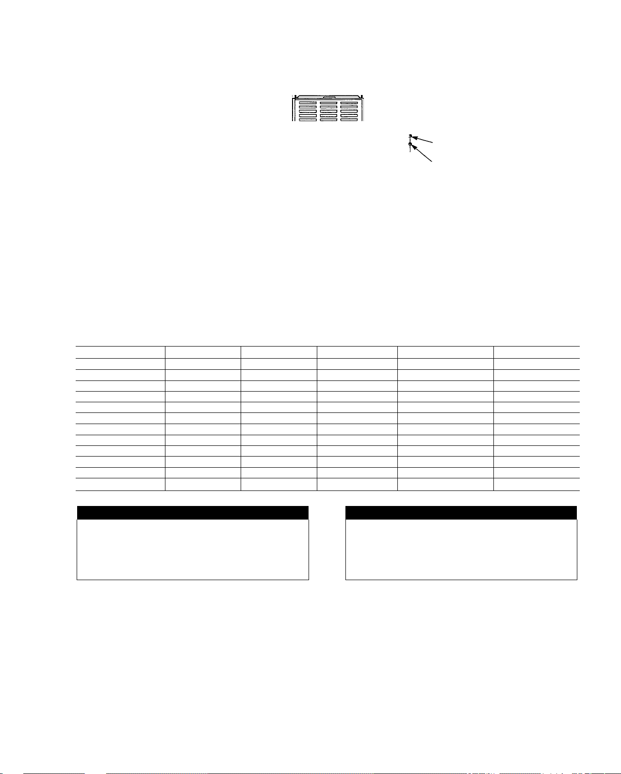
CONFINED SPACE
A confined space MUST have 2 permanent openings, 1 within 12
in. of the ceiling, and the other within 12 in. of the floor. (See Fig.
2.)
NOTE: In determining the free area of an opening, the blocking
effect of the louvers, grilles, and screens must be considered. If the
free area of a louver or grille design is unknown, it may be
assumed that wood louvers have a 20 percent free area and metal
louvers or grilles have a 60 percent free area. Screens, when used,
must not be smaller than 1/4-in. mesh. Louvers and grilles must be
constructed so they cannot be closed.
SUPPLY
AIR
VENT THROUGH ROOF
(CATEGORY 1) OR WALL
(CATEGORY 111)
~r~
_12MAX
Q_i
1 SO IN.
Щ PER 1000
BTUH*
INTERIOR
HEATED
SPACE
6 IN. MIN
(FRONT) t
1 SO IN.
PER 1000
BTUH*
* Minimum opening size is 100 square in. with
minimum dimensions of 3 in.
1 Minimum of 3 in. when type-B vent is used.
A89012
Fig. 2—Air For Combustion and Ventiiation
(inside Air)
The size of the openings depends upon whether the air comes from
inside or outside of the structure.
1. All air from inside the structure
Each opening MUST have at least 1 square in. of free area per
1000 Btuh of the total input for all equipment within the
confined space, but not less than 100 square in. per opening.
(See Fig. 2.) The minimum dimension of air openings shall be
not less than 3 in.
For Example:
58TUA FURNACE
HIGH FIRE INPUT
BTUH
40,000
60,000
80,000
100,000
120,000
140,000
FREE AREA OPEN
ING (SQUARE IN.)
100
100
100
100
120
140
If the building is constructed unusually tight, a permanent opening
directly communicating with the outdoors should be provided.
This opening shall have a minimum free area of 1 square in. per
5000 Btuh of total input rating for all equipment in the enclosure.
If the furnace is installed on a raised platform to provide a
return-air plenum, and return-air is taken directly from the hallway
or space adjacent to the furnace, all air for combustion must come
from outdoors.
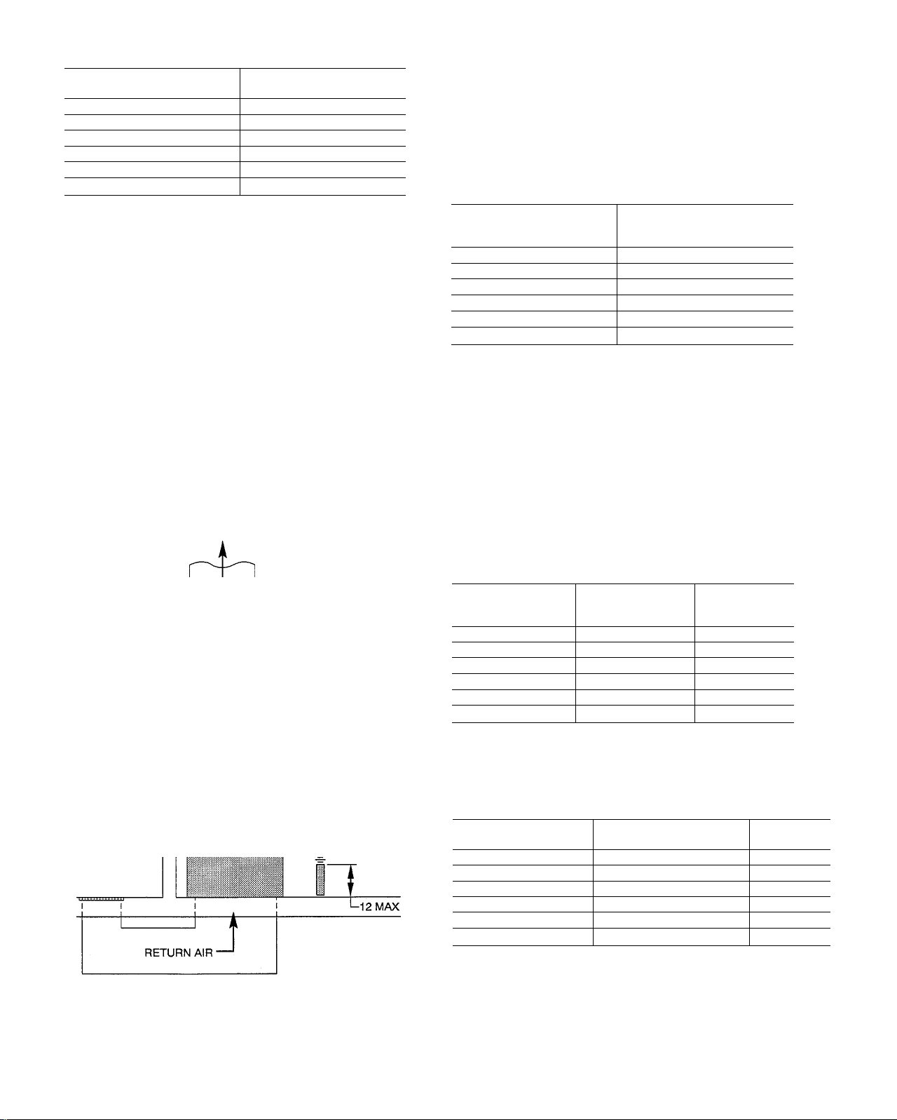
2. All air from outdoors
a. If combustion air is taken from outdoors through vertical
ducts, the openings and ducts MUST have at least 1 square
in. of free area per 4000 Btuh of the total input for all
equipment within the confined space. (See Fig. 3.)
For Example:
58TUA FURNACE
HIGH FIRE INPUT
BTUH
40,000 10.0
60,000
80,000 20.0
100,000 25.0
120,000 30.0 7
140,000 35.0
FREE AREA PER
OPENING
(SQUARE IN.)
15.0 5
ROUND PIPE
(IN. DIA)
4
6
6
7
b. If combustion air is taken from the outdoors through
horizontal ducts, the openings and ducts MUST have at
least 1 square in. of free area per 2000 Btuh of the total
input for all equipment within the confined space. (See Fig.
3)
For Example:
58TUA FURNACE
HIGH FIRE INPUT BTUH
40,000 20.0 6
60,000 30.0
80,000 40.0
100,000 50.0
120,000
140,000
FREE AREA PER OPENING
(SQUARE IN.)
60.0
70.0
ROUND PIPE
(IN. DIA)
10
When ducts are used, they must be of the same cross-sectional area
as the free area of the openings to which they connect. The
minimum dimension of rectangular ducts must not be less than 3
in. (See Fig. 3.)
7
8
8
9
A WARNING
Do not install the furnace on its back or sides. Safety control
operation will be adversely affected. Never connect return-air
ducts to the back of the furnace. A failure to follow this
warning can cause a fire, personal injury, or death.
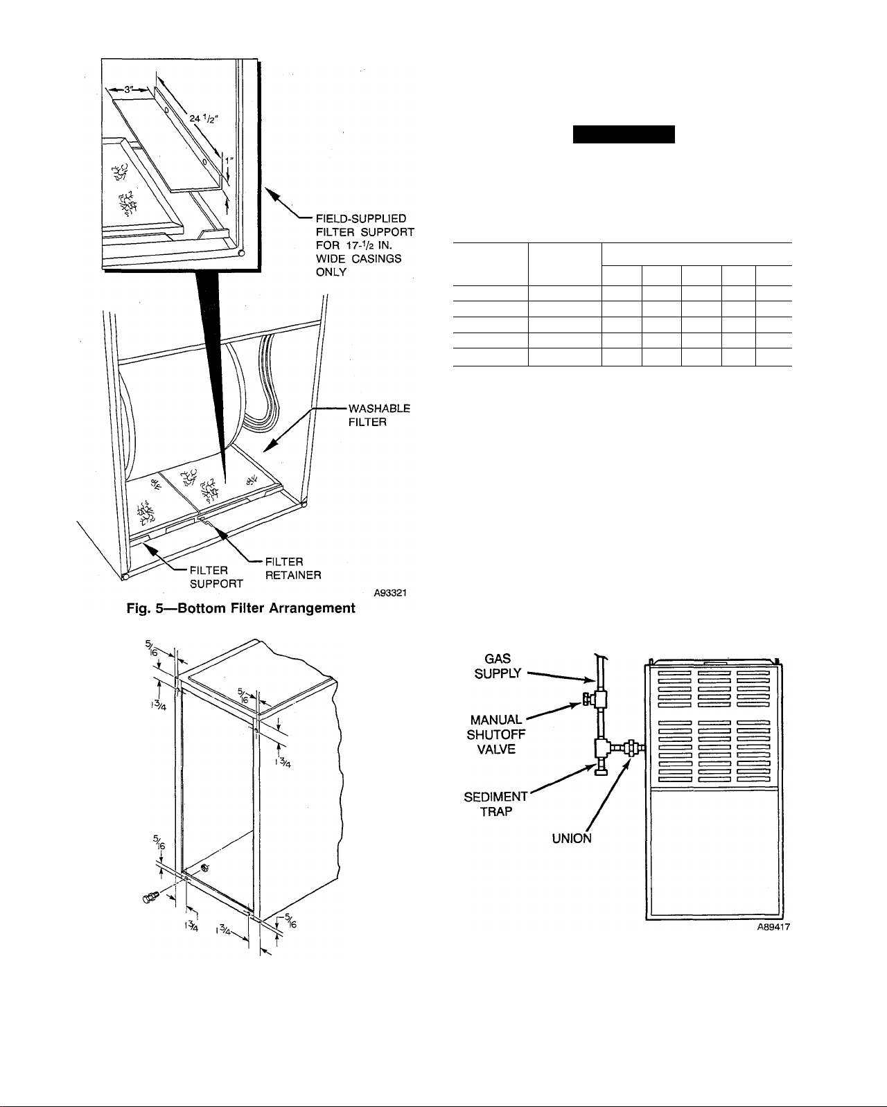
Step 3—FILTER ARRANGEMENT
The factory-supplied filter(s) is shipped in the blower compart
ment. Determine location for the filter and move filter retaining
hardware, if necessary, before attaching the return-air duct. After
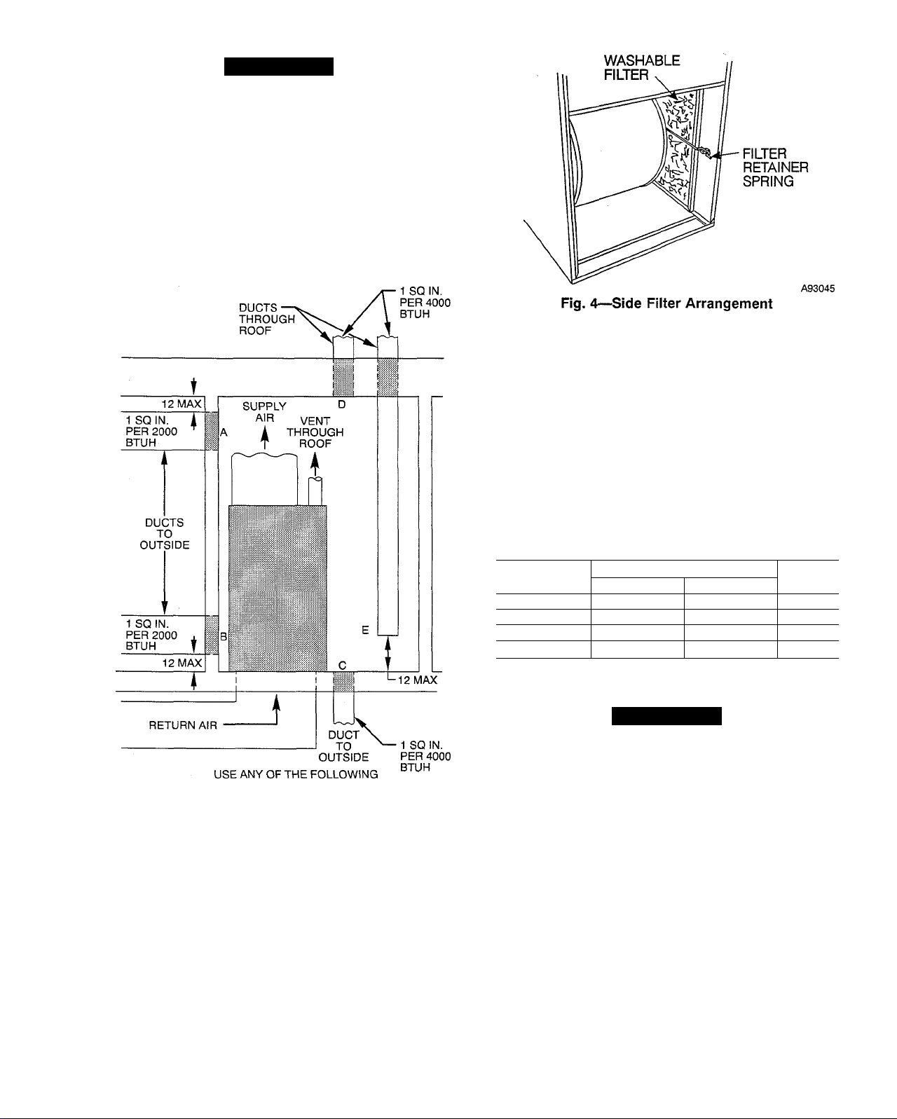
the return-air duct has been connected to the furnace, install the
filter(s) inside the furnace blower compartment. See Fig. 4 for side
return application and Fig. 5 for bottom return application.
reinstall. (Do not reinstall in 17-1/2 in. casing.) Install the filter
retaining rod (small U-shaped end) in the rear bracket, and the
front of the filter retainer rod as shown in Fig. 5. Two sets of
hardware are needed for furnaces in 24-1/2 in. casings using 2
filters for bottom return. All hardware is provided for filter
installation.
NOTE: Furnaces with a 17-1/2 in. wide casing require an
additional procedure when locating the filter for bottom return-air
application. Field-fabricate a sheet metal filler strip 1 X 3 X 24-1/2
in. and install it along side of the filter as shown in Fig. 5. Drive
2 screws through the casing side and into the filler strip to secure
it in place. Filter is to rest on top of the filler strip when installed.
COMBINATIONS OF OPENINGS:
A&B C&D D&E
A89013
Fig. 3—Air For Combustion and Ventilation
(Outside Air)
A bottom closure panel is factory installed in the bottom of the
furnace. When bottom return inlet is desired, remove and discard
the enclosure panel.
Filter-retaining brackets, supports, and retainers are factory assem
bled and shipped installed for side return application, with 1 set of
all required hardware on each furnace. (See Fig. 4.)
For bottom return applications, remove the brackets (front and
back) and supports from each side. The back bracket(s) are
installed in the rear of the furnace casing (dimples are provided to
mark mounting screw locations).
The front bracket(s) are installed on the bottom front plate as
shown in Fig. 5, once the bottom enclosure has been removed.
Rotate filter supports 180° so filter will rest on support, and
Table 3—Filter Information (In.)
FURNACE
CASING WIDTH
14-3/16
17-1/2
21 (1) 16X25X 1 (1) 20 X 25 X It
24-1/2
‘Filters can be field-modified by cutting the frame as marked and folding to the
desired size. Alternate sizes can be ordered from your distributor or dealer.
tFactory provided with the furnace.
Side Return Bottom Return
(1) 16 X 25 X It
(1) 16X25X1t
(2) 16X25X1t
FILTER SIZE*
(1) 14X25X1
(1) 16 X 25 X 1
(1) 24X25X1 Cleanable
FILTER
TYPE
Cleanable
Cleanable
Cleanable
A WARNING
Never operate unit without a filter or with filter access door
removed. A failure to follow this warning can cause a fire,
personal injury, or death.
Step 4—LEVELING LEGS (If Required)
When the furnace is used with side inlet(s) and leveling legs are
required, refer to Fig. 6 and install field-supplied corrosionresistant 5/16-in. machine bolts and nuts.
NOTE: The length of the bolt should not exceed 1-1/2 in.
1. Lay furnace on its back, locate and drill 5/16-in. diameter hole
in each bottom comer of furnace as shown in Fig. 6.
2. Install nut on bolt and install bolt and nut in hole. (Install flat
washer if desired.)
3. Install another nut on other side of furnace base. (Install flat
washer if desired.)
4. Adjust outside nut to provide desired height, and tighten inside
nut to secure arrangement.
Step 5—GAS PIPING
Gas piping must be installed in accordance with national and local
codes. Refer to the current edition of the National Fuel Gas Code.
The gas supply line should be a separate line running directly from
the gas meter to the furnace, if possible. Refer to Table 4 for the
recommended gas pipe size. Risers must be used to connect to the
furnace and the meter.
A CAUTION
If a flexible connector is required or allowed by the authority
having jurisdiction, black iron pipe shall be installed at the
gas valve and extend a minimum of 2 in. outside the furnace
casing.
Table 4—Maximum Capacity of Pipe*
NOMINAL
IRON PIPE
SIZE (IN.)
1/2 0.622 175
3/4 0.824
1
1-1/4
1-1/2
* Cubic ft of gas per hr, for gas pressures of 0.5 psig (14-in. wc) or iess, and
a pressure drop of 0.5-in. wc (based on a 0.60 specific gravity gas). Ref: Table
10-2, NFPA 54-1992.
Piping should be pressure-tested in accordance with local and
national plumbing and gas codes before the furnace has been
attached. If the test pressure exceeds 0.5 psig (14-in. wc), the gas
supply pipe must be disconnected from the furnace and capped
before the pressure test. If the test pressure is equal to or less than
0.5 psig (14-in. wc), close the manual shutoff valve located on the
gas valve before the test. It is recommended that the ground joint
union be loosened before pressure testing. After all connections
have been made, purge the lines and check for leakage with
regulated gas supply pressure.
Install a sediment trap in the riser leading to the furnace. The trap
can be installed by connecting a tee to the riser leading from the
furnace. Connect a capped nipple into the lower end of the tee. The
capped nipple should extend below the level of the gas controls.
(See Fig. 7.)
INTERNAL
DIAMETER
(IN.)
1.049 680
1.380 1400
1.610 2100
LENGTH OF PIPE (FT)
20 30 40 50
10
120
250 200 170 151
360
465 375
950 770 660 580
1460 1180
97 82
320
990
73
285
900
A89014
Fig. 6—Leveling Leg Installation
Canadian installations must be installed in accordance with
CAN/CGA-B149 Installation Codes, and all authorities having
jurisdiction.
Fig. 7—^Typical Gas Pipe Arrangement
Apply joint compound (pipe dope) sparingly and only to the male
threads of each joint. The compound must be resistant to the action
of propane gas.
Install an accessible manual shut-off valve upstream of the furnace
gas controls and within 72 in. of the furnace. A 1/8-in. NPT
plugged tapping, accessible for test gage connection, must be
 Loading...