

Carrier 58SX040-IBC User Manual
58SX040-IBC
HEATING A COOLING
Deluxe Gas-Fired Condensing Furnaces
Application Data
Installation Guidelines—Procedures
INTRODUCTION
Portions of the following instructions have been adopted in
part from the current edition of the National Fuel Gas Code
NFPA No. 54, TIA-54-1984-1/ANSI Z223.1-1984, Z223.1a1987 and American Gas Association. For further details,
consult this pubhcation, or the current edition available
from National Fire Protection Association, Inc., Batterymarch Park, Quincy, MA 02269, or American Gas Associa
tion, 1515 Wilson Boulevard, Arhngton, VA 22209.
These instructions cover minimum requirements and con
form to existing national standards and safety codes. In
some instances, these instructions exceed certain local
codes and ordinances, especially those that may not have
kept pace with changing residential construction practices.
Carrier requires these standard procedures as a minimum
for a safe installation.
Refer also to regulations of the local gas supplier as well as
to local building, heating, plumbing, or other codes in effect
in area in which installation is made.
A CAUTION
Application of this furnace should be indoors with spe
cial attention given to vent sizing and material, gas
input rate, air temperature rise, and unit sizing.
Improper installation or misapphcation of the furnace
can require excessive servicing or cause premature com
ponent failure.
(Only)
CONTENTS
Page
INSPECTION........................................................................ 1
FURNACE LOCATION..........................................................1
GAS PIPING
COMBUSTION-AIR AND VENT PIPING
CONDENSATE DRAIN ........................................................ 5
ELECTRICAL CONNECTIONS
START-UP, ADJUSTMENT, AND
SAFETY CHECK
Available power supply must meet specifications on furnace
rating plate and on all motors in the equipment.
Check the available gas supply to see that it conforms to
the gas specification on the A.G.A. rating plate.
Locate the furnace as near the center of the air distribution
system as possible.
This furnace may be located in a confined space without
special provisions for dilution or ventilation air.
Provide ample space for servicing and cleaning. Always
comply with the minimum fire protection clearances shown
on the unit rating plate. This furnace must NOT be installed
directly on carpeting, tüe, or any combustible material other
than wood flooring.
.......................................................................
............................
............................................
................................................................
INSPECTION
FURNACE LOCATION
1,2
2-5
5
5-7
This furnace is designed for a minimum continuous return
edr temperature of 60 degrees F DB or an intermittent oper
ation down to 55 degrees F DB such as when used with a
thermostat night setback.
A WARNING
Never store anything on, or in contact with, the fur
nace, such as:
Spray or aerosol cans, rags, brooms, dust mops, vac
uum cleaners, or other cleaning tools.
Soap powders, bleaches, waxes or other cleaning com
pounds, plastic or plastic containers, gasoline, kerosene,
cigarette lighter fluid, dry-cleaning fluids, or other vola
tile fluids.
Paint thinners and other painting compounds, paper
bags or other paper products.
A failure to adhere to this warning can cause corrosion
of the heat exchanger and vent system, fire, personal
injury, or death.
Manufacturer reserves the right to discontinue, or ohange at any time, specifications or designs without notice and without incurring obligations.
Book| 1 PC 101 Catalog No. 515-820 Printed in U.S.A. Form 58SX-9XA Pg 1 1-88 Replaces: 58SX-7XA
Tab l6a
Do not install furnace in unconditioned space that could
experience temperatures of 32 F or lower.
NOTE: For proper furnace operation, the furnace must be
installed within 1/2 in. of level.
When furnace supply ducts dehver air to areas outside the
space containing the furnace, return air ducts must also be
sealed to furnace casing and must terminate outside the
space containing the furnace. Otherwise, a negative pres
sure condition could develop within equipment room or
space.
Furnace Location Relative to Cooling Equipment—Install
cooling coU in parallel with, or on downstream side of, fur
nace to reduce potential for condensation in heat exchanger.
When a coU is installed in parallel with a furnace, deimpers
or other means used to control airflow must prevent chilled
air from entering furnace. For manual damper operation,
equip dampers with a means of preventing operation of
either unit unless deimper is in the fuU-heat or fuU-cool
position.
A CAUTION
Special Locations—When installing furnace in a residential
garage, protect it from physical damage by vehicles. Fur
naces installed in public garages, airplane hangers, or other
buildings having hazardous atmospheres must comply with
requirements of the National Fire Protection Association,
Inc.
GAS PIPING
Gas piping must be installed in accordance with national
and local codes.
Run a separate gas supply hue directly from the meter to
the furnace, if possible. Table 1 shows recommended gas
pipe sizing. Slope all pipe 1/4 inch in 15 ft to prevent traps.
Slope aU horizontal runs away from meter and toward
risers. Use risers to connect lines to furnace and meter.
Apply joint compounds (pipe dope) sparingly and only to
male threads of joints. Consult local gas supplier for com
pound recommendations.
NOTE: Use only compounds resistant to the action of LP
(propane) gas.
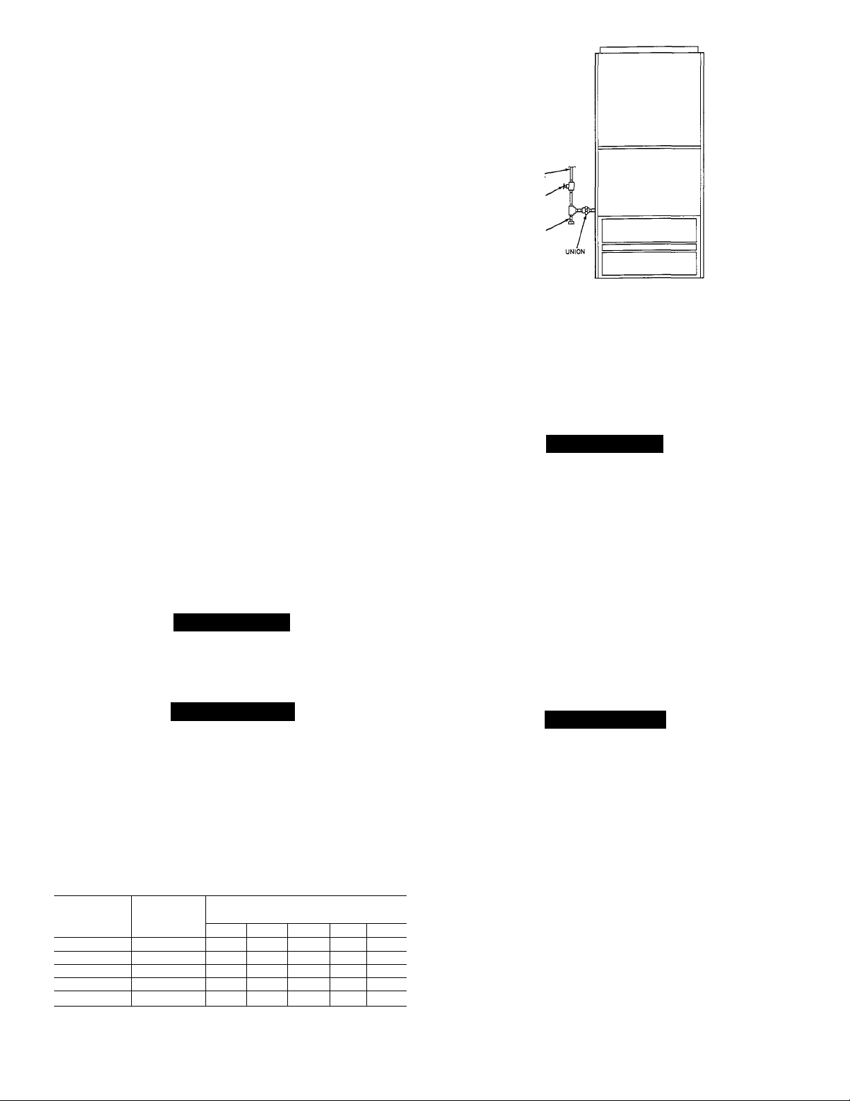
Install a sediment trap in the riser leading to the furnace to
trap dirt and condensate. Connect a tee to the riser leading
to the furnace, keeping straight-through section of tee verti
cal. Connect a capped nipple into lower end of tee, so that
nipple extends below level of gas controls (Fig. 1).
Where a gum filter is required by local codes, install it in
accordance with their requirements.
An accessible manual shutoff valve must be installed
upstream of furnace gas controls and within 6 ft of furnace.
A 1/8-in. NPT plugged tapping, accessible for test-gage con
nection, must also be installed immediately upstream of gas
supply connection to furnace and downstreeun of manual
shutoff valve.
Install a ground joint imion between gas control manifold
and manual gas shutoff valve (Fig. 1).
A CAUTION
Use a backup wrench when connecting gas pipe to fur
nace to avoid damaging gas controls.
MANUAL
SHUTOFF
VALVE
A84218
Fig. 1—Ground Joint Union and Sediment Trap
sizes larger than 1/2 in., foUow recommendations of national
codes.
A CAUTION
If a flexible connector is required or allowed by the
authority having jurisdiction, black iron pipe must be
installed at the gas valve and extend a minimum of 2 in.
outside the furnace casing.
Pressvue-test piping in accordance with local and national
plumbing and gas codes before attaching furnace. Crack
ground joint union before pressure testing. If pressure
exceeds 0.5 psig (14 in. wc), disconnect gas supply Une from
furnace before performing pressure test. If test pressure is
equal to or less than 0.5 psig (14 in. wc), close manual shut
off valve located on gas valve before testing.
After final connection to the furnace has been made, purge
lines and check for leakage with regulated gas supply
pressure.
A WARNING
Use the proper length of pipes to avoid stress on the
gas control manifold. A failure to adhere to this warn
ing can cause a gas leak resulting in a fire, explosion,
physical injury, or death.
Protect all segments of the piping system agEunst physical
and thermal damage. Support aU piping with appropriate
straps or hangers (one hanger every 6 ft rninimum). For pipe
Table 1—Maximum Capacity of Pipe*
NOMINAL
IRON PIPE
SIZE (in.)
1/2
3/4 0.824
1 1.049
1-1/4
1-1/2
Ref: Table C-4 NFPA 54-1984
♦Cubic ft of gas per hour, for gas pressures of 0.5 psig (14 in. wc) or less,
and a pressure drop of 0.5 in. wc (based on a 0.60 specific gravity gas).
INTERNAL
DIAMETER
(in.)
0.622 175 120 97 82 73
1.380 1400 950
1.610
2100 1460
LENGTH OFPiPE(ft)
20
10
360 250
680 465 375 320 285
30 40 50
200 170
660 580
770
1180 990
151
900
A WARNING
Never purge line into combustion chamber. Never use
matches, candles, flame, or other sources of ignition to
check for gas leakage. Use a soap-and-water solution to
check for leaks. A failure to adhere to this warning can
cause a fire, explosion, physical injtuy, or death.
COMBUSTION-AIR AND VENT PIPING
The combustion-air and vent pipe and fittings must con
form to American National Standards Institute (ANSI)
standards and American Society for Testing and Materials
(ASTM) standards D1785 (schedule-40 PVC), D2665 (PVCDWV), D2441 (SDR-21 and SDR-26 PVC) or D2661 (ABSDWV). Pipe cement and primer must conform to ASTM
standards D2564 (PVC) or D2235 (ABS). See Table 3 for
pipe sizing and Fig. 3 through 5 for exterior piping arrange
ments. See “High-Altitude Pipe Sizing Procedures” section
for high-altitude applications.
The unit is shipped with a 2-1/2 x 2-1/2-in. rubber coupling.
An optional coupling size 2-1/2 x 2-in. is available through
the Distributor or Branch. See the Replacement Parts cata
log for the part number.
—2—
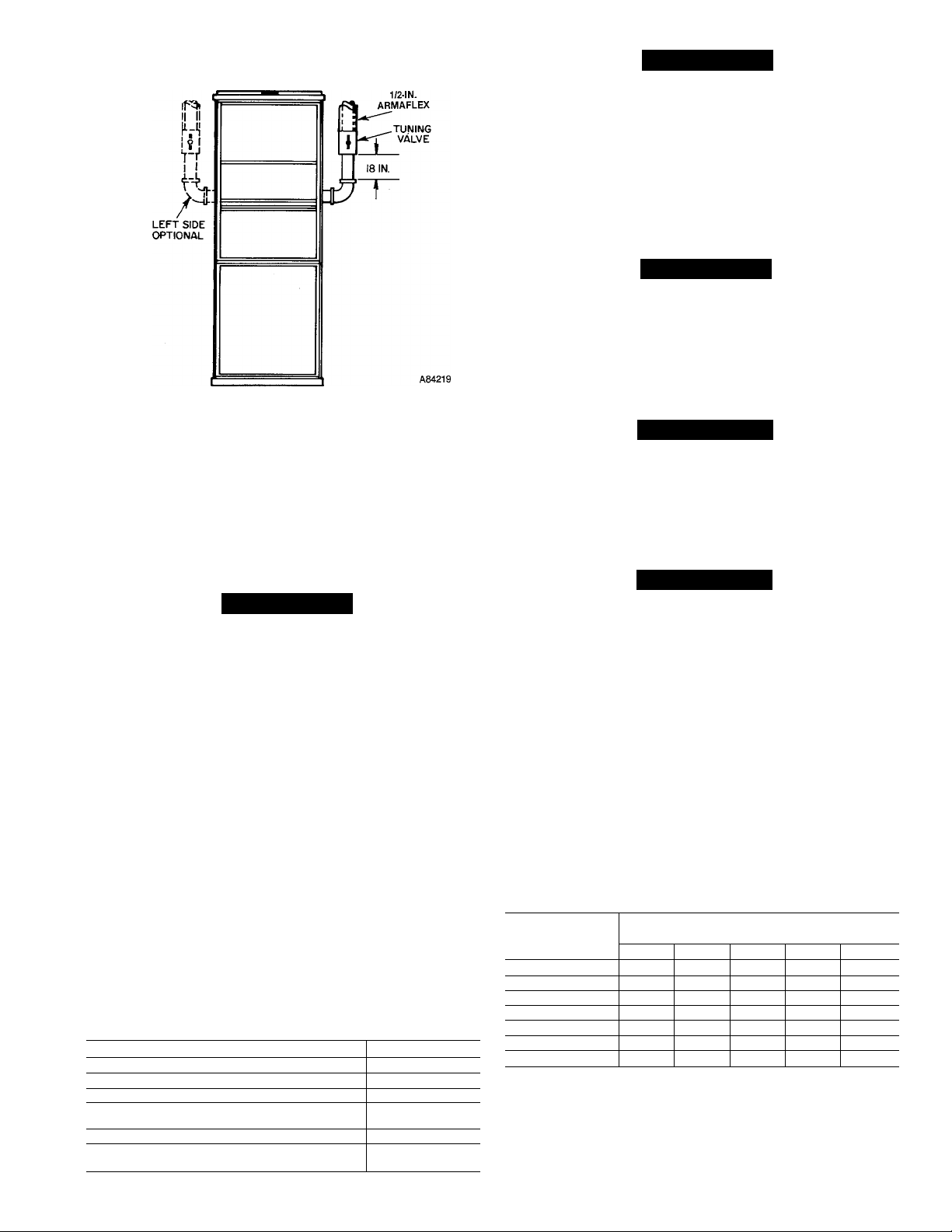
Fig. 2—Tuning Vaive Location
The accessory vent terminal kit described below must be
used in constructing the vent terminal for this imit. Pipes
must terminate through either the roof or the sidewall; roof
termination is preferable. Locate sidewall terminations to
prevent damage to shrubs, condensing unit, and siding
materials. Table 2 gives clearance requirements.
A CAUTION
Combustion air must not be taken from inside the
structure because that air frequently is contaminated
by halogens, which include fluorides, chlorides, bro
mides, and iodides. These elements are found in aero
sols, detergents, bleaches, cleaning solvents, salts, air
fresheners, and other household products. Vapors from
these products are highly corrosive to gas-fired fur
naces, even in extremely low concentrations (as low as
0.5 ppm).
Maintain a minimum of 36-in. between combustion-air
inlet and clothes-dryer vent.
Locate the combustion-air inlet as far as possible from
the switnrning pool and swimming pool pump house.
NOTE: When a previously common-vented system (furnace
and water heater) is converted to water heater only, the
vent system may be drastically oversized for the water
heater. Consult the National Fuel Gas Code for proper siz
ing of the vent and revise the system if necessary.
Table 2—Combustion-Air and
Vent Terminal Clearances
LOCATION
Dryer vent 3ft
From plumbing vent stack 3ft
Gas appliance vent terminal
From any opening where vent gases
could enter building
Above grade and anticipated snow depth
Above grade when adjacent to public
walkway
CLEARANCE
4 ft
12 in.
12 in.
7ft
A CAUTION
When the vent pipe is exposed to temperatures below
freezing i.e. when it passes through an unheated space
or when a chimney is used as a raceway, the pipe must
be insulated with 1/2-inch thick Armaflex-type
insulation.
NOTE: The vent pipe must be insulated with 1/2-in. thick
Armaflex insulation from the tuning valve to the point
where the pipe exits the structme.
A CAUTION
When the combustion-air pipe is installed above a sus
pended ceiling, the pipe must be installed with 1/2-in.
Armaflex insulation.
The combustion-air pipe should also be insulated in warm,
humid spaces such as basements.
A WARNING
Solvent cements are combustible. Keep away from heat,
sparks, and open flame. Use only in weU ventilated
areas. DO NOT breathe vapors. Avoid contact with the
skin or eyes. A failure to adhere to this warning can
cause a fire or physiceil injury.
A WARNING
All combustion-air and vent pipes must be airtight and
watertight. Pipes must terminate exactly as shown in
Fig. 3 through 5. A failure to adhere to this warning can
cause property damage, physical injury, or death.
Furnace is shipped from factory assembled for right-hand
vent pipe connection. When left-hand vent connection is
desired, remove cap from left-hand side of inducer outlet
box and install over hole in right-hand side of box.
Remove plastic plug from left-hand casing side panel and
install plug in unused hole in the right-hand casing side
panel.
Install the turning valve in the vertical riser of the vent pipe
18 in. above the elbow, as shown in Fig. 2.
To install piping:
Table 3—Pipe Diameter (in.)
PIPE
LENGTH
(ft)
5 2 2 2 2
10 2 2
15
20
25
30 2 2
35 2 2
NOTES:
1. Assume two 45° elbows equal one 90° elbow.
2. Diameters listed are for schedule-40 PVC, PVC-DWV or ABS-DWV pipe.
3. Long radius elbows are desirable.
4. Elbows and pipe sections supplied in vent terminal kit should not be
included in count.
5. Do not exceed 35 linear feet.
1 2 3 4 5
2
2
2
NUMBER OF 90° ELBOWS
(See Notes)
2 2 2
2 2 2 2
2 2 2
2 2 2 2
2 2 2
2 2 2
2
2
-3—
 Loading...