

Page 1
58SSB
... ..„„0 .0 Accessory Variable Speed Blower Kit
Installation Instructions
GENERAL
These instructions cover installation of an ECM blower
accessory on 2- and 3-ton cooling 58SSB 060 and 080
furnaces. ECM blower accessory Part No. 58SSB900131
is used on 2-ton cooling 58SSB060 furnace and Part No.
58SSB900141 is used on3-toncooling58SSB080furnace.
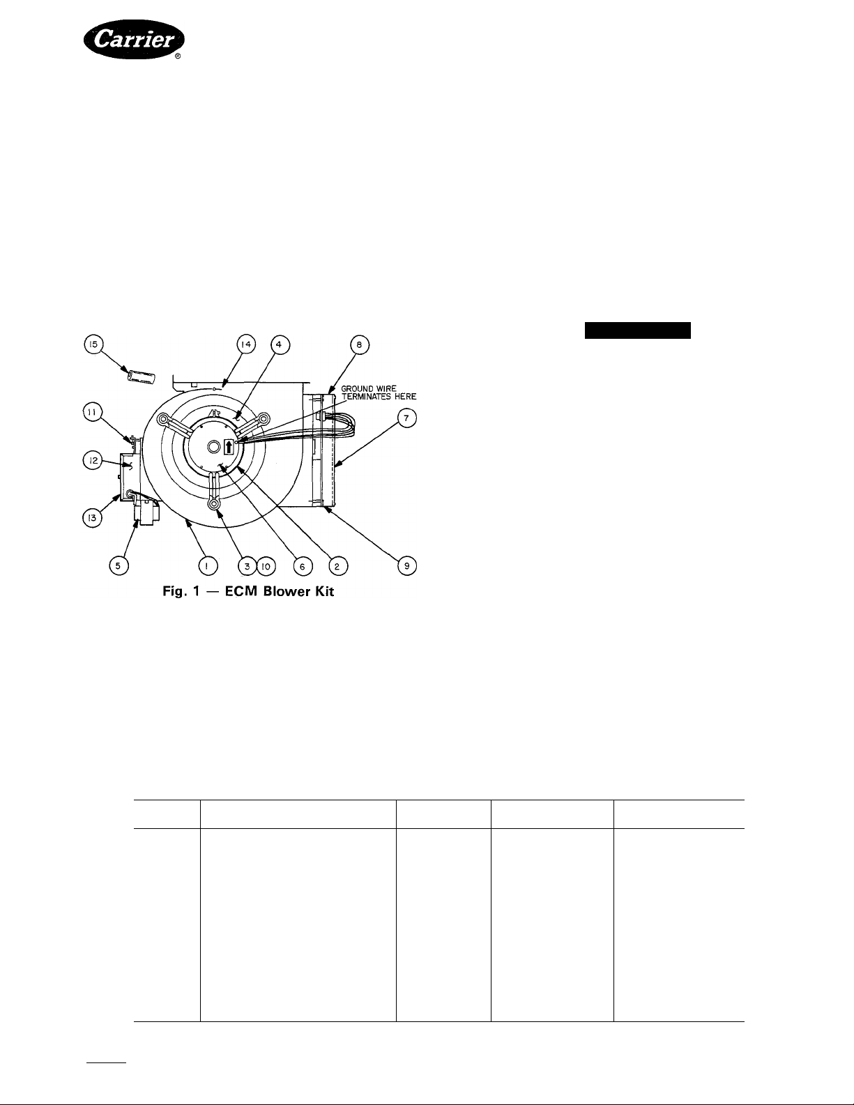
Each ECM blower kit comes completely assembled
with an ECM blower motor and controller, and interface
circuit board. See Table 1 for a list of parts in assembly
shown in Fig. 1.
ECM blower kit is used in conjunction with following
variable speed outdoor units:
38EV024320
38EV036320
38QV024320
38QV036320
This ECM blower is controlled by outdoor unit and
provides variable airflow across furnace coil in response
to variable demand on heat pump or air conditioner. For
emergency heat, interface circuit board allows furnace
control board to operate ECM blower at a fixed rate of
speed. This speed is normally adjusted to midpoint of
rating plate temperature rise range. Interface circuit
board also powers a Parker indoor thermostat. Part No.
HH05ZA001.
Installation of indoor coil expansion valve, and start
up and adjustment instructions are covered in Installa
tion, Start-Up and Service Instructions for the 38EV,QV
outdoor units. See detailed system operation and control
in the 38EV,QV system operation and troubleshooting
guide.
A WARNING
Turn off power at main disconnect switch before
starting installation to avoid possibility of electrical
shock.
TABLE OF CONTENTS
Page
INSTALLATION ..................................................................1-4
SEQUENCE OF OPERATION
TEMPERATURE RISE ADJUSTMENT
CARE AND MAINTENANCE
INSTALLATION
The following steps should be performed by a qualified
service person:
1. Turn off power at main disconnect.
2. Remove blower door.
3. Remove control box from bottom side of blower
shelf and position out of way.
4. Remove electrical leads from numbered side of
blower speed selector.
5. Remove screws securing blower assembly to blower
shelf and slide blower assembly out of furnace.
6. Unpackage ECM blower assembly and set the
minimum and maximum torque settings on ECM
blower control via access in lower mounting bracket
as shown in Fig. 2.
.........................................
....................
..........................................
5
6
6,7
Table 1 — ECM Blower Kit Parts List
ITEM
1
2
3
4
5
6
7
8
9
10
11
12
13
14 Cutoff, Blower 1
15
Manufacturer reserves the right to discontinue, or change at any time, specifications or designs without notice and without incurring obiigations.
Book|1 14 PC101 Catalog No. 535-857 Printed in U.S.A. Form58SSB-5SI Pgl 4-87 Replaces:New
Tab |6a|8a
Housing-Blower
Band-Motor Mount
Arm-Motor Mount
Wheel-Blower
T ransformer
Motor (ECM) 1
ECM Motor Controller
Top Blower Control Bracket
Grommet-Isolator
Interface Board
Interface Box
Interface Box Cover
Electrical Noise Suppressor 1
DESCRIPTION
Bottom Blower Control Bracket
QUANTITY
1
1
3
1
1
1
1
1
3
1
1
1
58SSB900131
PART NO.
58SSB309891-701
HC98ZZ480
HC98ZZ242
LA22RA101
HT01AW232
HC42SE113
HR46KH001
58SSB308056-201
58SSB308056-202
09-0135
HK42FA002
58SSB309863-401
58SSB309864-301
79725-2
HK99FA001
58SSB900141
PART NO.
58SSB309891-702
HC98ZZ480
HC98ZZ248
LA22RA100
HT01AW232
HC42SE113
HR46KH001
58SSB308056-201
58SSB308056-202
09-0135
HK42FA002
58SSB309863-401
58SSB309864-301
79725-3
HK99FA001
Page 2
TORQUE SELECT
[ 1
pnnnnnnn
r)
pmnnnnf^
MIN.
LIMIT
, (WHITE)
FURNACE
SIZE
58SSB060 3 7
58SSB080
MIN
SETTING
3
Fig. 2 — Torque Setting
7. Slide ECM blower assembly into furnace and tighten
screws to secure blower assembly to the blower shelf.
8. Reinstall furnace control box on bottom side of
blower shelf.
9. Connect electrical leads from furnace control pre
viously used as blower speed selector taps to
numbered connector which is panel mounted on the
left side of the interface control box. Black lead to
position 1, red lead to position 2, white lead to posi
tion C.
10. Double-check to make sure main power disconnect
is off.
In steps 11 through 14, the 115-v power leads to ECM
blower icit connects in parallel with furnace 115-v power
supply. To do this:
11. Remove cover of auxiliary junction box.
|j
^ MAX.
LIMIT
(BLACK)
SETTING
MAX
10
12. Remove strain relief securing the power leads in place
on the auxiliary J-box.
13. Route power leads from ECM blower kit through
opening in back of auxiliary junction box. Dis
connect black lead from furnace control at door
switch, and connect black lead with 3/16-in. piggy
back quick-connect from ECM blower kit in its place.
Then reconnect black lead from furnace control to
3/16-in. male quick-connect provided on piggyback
connector. Remove wire connecting white lead of
furnace control to line voltage common line. Connect
white wire from ECM blower kit and reinstall wire
nut.
14.
Make sure all power leads are secured in place using
the strain relief provided with this kit.
Reinstall cover to auxiliary junction box.
15.
Disconnect all existing thermostat leads from the
16.
furnace control board if applicable.
Connect W, R, and C from terminal block TB3
17.
labeled, HEAT, on interface circuit board located on
front of blower housing to their respective thermostat
connections on furnace control board, labeled (W,
R, C) using field-supplied thermostat wire cut 6 in.
in length and stripped 1 /4 in. on each end. See Fig. 3.
18.
Install thermostat following instructions included
with outdoor section. For single zone applications,
route 6-conductor thermostat wire into furnace
through one of the knock-outs in the cabinet. Multi
zone applications require only 3-conductor wire.
Slide electrical noise suppressor provided, over
19.
thermostat wire before making electrical connections
(see Fig. 3) at blower assembly.
NOTE; For electrical interference and noise, refer to
38EV,QV outdoor section Installation, Start-Up and
Service Instructions.
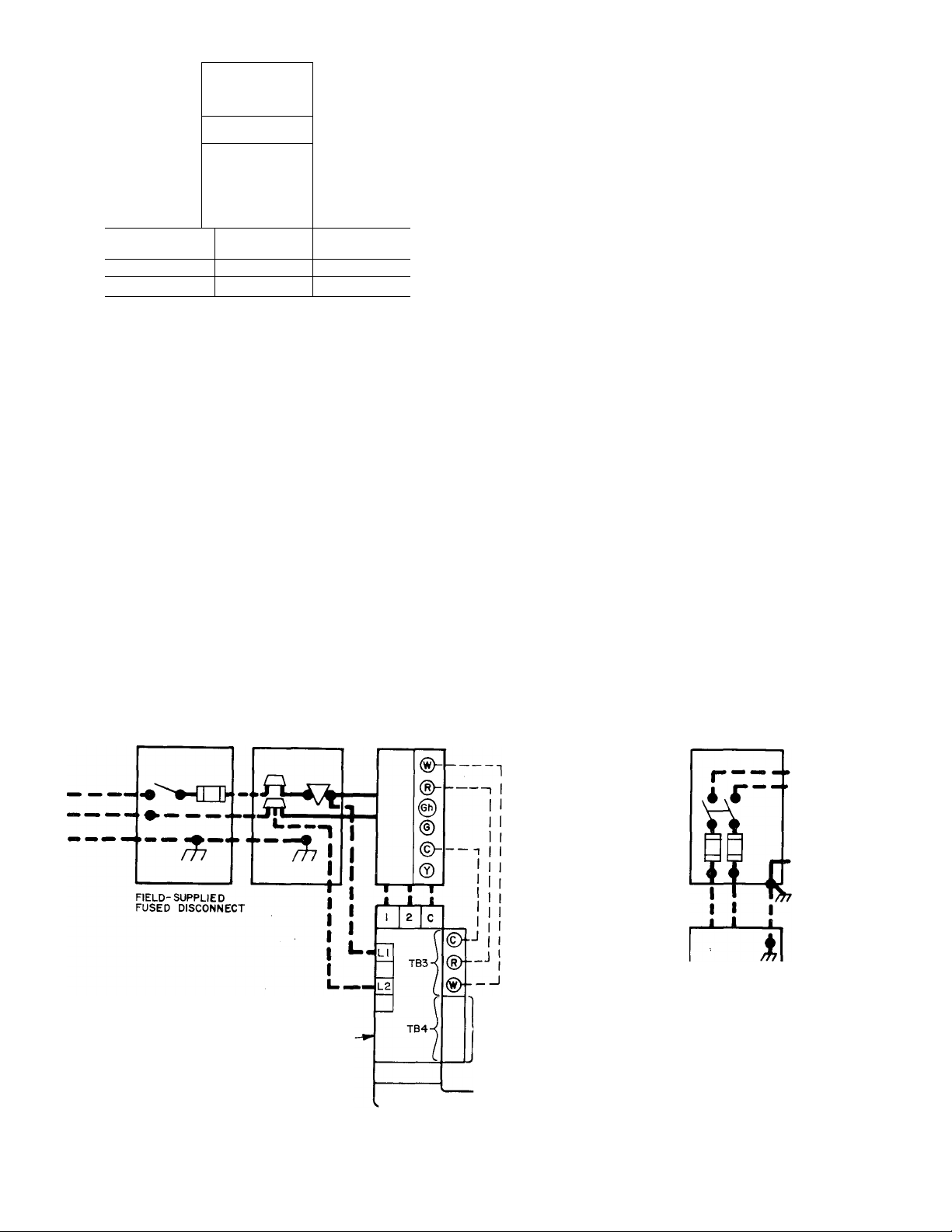
AUXILIARY
JUNCTION BOX
ECM BLOWER KIT
INTERFACE BOARD-
FIELD LOW-VOLTAGE WIRING
■ FIELD HIGH-VOLTAGE WIRING
FACTORY LOW-VOLTAGE WIRING
LOW-VOLTAGE
TERMINAL BLOCK
PARKER INDOOR
THERMOSTAT TERMINALS
ELECTRICAL
NOISE
SUPPRESSOR
----------------------
THERMOSTAT LINE
(SEE FIG. 4a OR FIG. 4b
FOR CONNECTIONS)
INTERFACE CABLE
► SINGLE
PHASE
VAR. SPEED
CONDENSING
1
UNIT
NOTE: If any of the original wire as supplied must be replaced, use same type or equivalent wire.
Fig. 3 — Field High- and Low-Voltage Wiring Diagram
Page 3
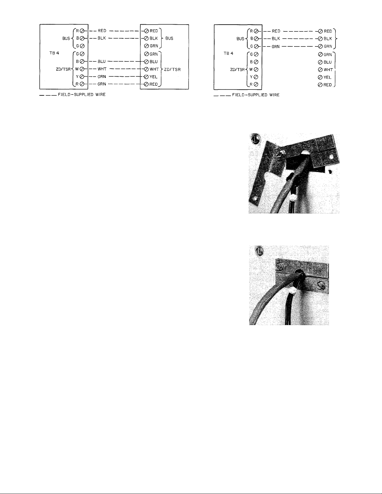
INTERFACE BOARD
PARKER
INDOOR THERMOSTAT INTERFACE BOARD
PARKER
INDOOR THERMOSTAT
BUS
VZD/TSR
4a — SINGLE ZONE
Fig. 4 — Thermostat Connections
20. Strip thermostat wire leads back 1/8-in. and make
connections to blower kit interface board as shown
in Fig. 4a or 4b. Slide noise suppressor down thermo
stat wire and position close to interface board.
21. Route interface cable provided with Model 38EV or
QV outdoor unit to furnace, as described in Model
38EV,QV installation instructions.
22. To permit routing of interface cable into furnace
blower compartment it is necessary to modify furnace
cabinet according to the following procedure,
referring to Fig. 5.
a. Provided with kit are 2 sheet metal covers, screws
and snap bushing. See Fig. 5. Use one cover as a
template. Mark and drill two 1/8-in. diameter
mounting screw holes in either side of furnace
cabinet.
NOTE: Be sure to locate cable entry hole where
cable does not interfere with interior furnace com
ponents. Also, before making hole be sure cable
reaches proper receptacle (PI) on blower acces
sory interface board.
b. Use a chassis punch or similar tool to cut a 1 /2-in.
X 1-5/8 in. rectangular cable entry opening
between the 2 sheet metal cover mounting screw
holes to permit passage of interface cable
connector.
c. Mount the 2 sheet metal covers loosely to cabinet
with one screw. See Fig. 5.
d. Route interface cable through cable entry hole
into furnace blower compartment to receptacle PI
of blower accessory interface board. Connector is
polarized so it cannot be mounted in wrong direc
tion. Be sure spring clips on connector lock in
place to secure connector. Secure cable ground
wire to convenient interface board mounting
screw.
e. Mount indoor coil solenoid expansion valve
(SEV) as described in Model 38EV,QV outdoor
section installation instructions. Route 4-lead
wire harness from SEV through interface cable
entry hole to interface board polarized recep
tacle P2.
f. Open snap bushing provided and install busliing
around interface cable and 4 SEV leads at cable
entry hole with large rim of bushing facing out
ward from cabinet.
g. Slide 2 sheet metal covers together around bush
ing and secure covers loosely with remaining
mounting screw. Adjust cable and leads to allow
slack inside cabinet for strain relief.
h. Tighten both sheet metal cover mounting screws
with bushing positioned to protect cable and
leads from metal edges of cable entry hole.
4b — MULTI-ZONE
COVER DISASSEMBLED WITH
SNAP BUSHING ATTACHED TO LEADS
COVER FULLY ASSEMBLED
Fig. 5 — Cable Entry Hole and Cover
23.
Peel off backing from wiring diagram and stick on
top of previous furnace wiring diagram located on
inside of blower access panel.
24.
Reinstall control and blower access panels. See Fig. 3
for a wiring diagram showing proper field high- and
low-voltage wiring. Make all electrical connections
in accordance with National Electrical Code and any
local codes or ordinances that might apply.
25.
Clean 2-in. x 3-in. area next to unit rating plate.
Peel backing from auxiliary rating plate and stick to
26.
clean area next to unit rating plate.
NOTE: DO NOT apply auxiliary rating plate on top
of the unit rating plate. Make sure both rating plates
are legible after installation.
Page 4

CONNECTION DIAGRAM
SCHEMATIC (NAT'L a PROP)
MOTOR INTERFACE
CONTROLLER BOX
PCBl PCB2
, INTERNAL FUSE
ши (WHEN USED)
lA-TRANSFORHER, 120VAC/24VAC
2D-RELAY, INDUCER MOTOR DPST-N.O.
2E-RELAY, HEATING BLOHER (HER) SPST-K.C.
2F-RELAY, COOLING BLOHER (CFR) DPDT
3A-H0T0R, INDUCER
5F-VALVE, GAS (REDUNDANT)
6CI-B0ARD. P.C. (FURNACE CONTROL)
6C2-B0AR0, P.C. (INDUCER CONTROL)
•6C3-L0CK0UT MODULE
6F-GENERAT0R, SPARK (SOLID STATEl
6H-SHITCH. PILOT FLAME SENSING SPOT (740A)
7H1-SHITCH, LIMIT SPST-N.C.
7H2-SHITCH, DRAFT SAFEGUARD(SPST-N.C.) MANUAL RESET
7H3-SHITCH, AUXILIARY LIMIT(SPST-N.C.) MANUAL RESET
(HHEH USED)
7P-PRESSURE SHITCK, H.O.
7V-SHITCH, FLOH SENSING SPDT
9G-SHITCH, BLOHER DOOR INTERLOCK SPST-li.f.
FACTORY HIRING (120VAC)
FACTORY HIRING(24VAC)
—— FIELD HIRING (120VAC)
- CONDUCTORS ON 6C1 (FURNACE CONTROL BOARD)
CONDUCTORS OH 6C2 (INDUCER CONTROL BOARD)
@ SCREH TERMINAL FOR FIELD HIRING
t=3 1/4 INCH QUICK CONNECT TERMINALS
10B1-CONNECT0R. EDGE (FURNACE CONTROL BOARD)
1OB2-CONNECT0R, EDGE (INDUCER CONTROL B0ARD-7CKT.)
10B3-COHNECTOR, EDGE (INDUCER CONTROL B0ARD-2CKT.)
10B4-CONNECT0R. PILOT
10B5-FACT0RY TEST POINTS (NOT FOR FIELD USE)
1DB6-CONNECTOR, BLOHER MOTOR (PL3 ON PCB2)
IIB-FUSE, IN LINE 2AMP (HHEN USED)
11C-LIHK, FUSIBLE (OVER TEMPERATURE) (1 REQD. ON UPFLOH t
3 REQD. OH DOHNFLOH/KORIZONTAL FURNACE
llE-GROUHDj EQUIPMENT
HTRl-MOTOR (ECM) BLOHER
PCBI-P.C. BOARD (ECM BLOHERCONTROL )
PCB2-P.C. BOARD (INTERFACE)
T-3-THERMISTOR
TP)-TEST POINT
TRAN-24VAC TRANSFORMER
SEV-SOLENOID EXPANSION VALV:
c@=
5/>S
T2-INTERNALLY CONNECTED TO EQUIPMENT GROUND SPARK GENERATOR (6F)
MOUNTING SCREhS.
RELAY (2E) CONTACTS ARE NORMALLY CLOSED UNTIL 120VAC IS APPLIED
TO FURNACE.
IF ANY OF Tl
IT MUST BE I
BLOHER MOTOR (HTR-1) HAS A THERMAL OVERLOAD SWITCH.
BLOHER MOTOR (MTR-1) FACTORY SPEED ADJUSTMENTS ARE FOR AVERAGE
CONDITIONS. SEE ECM BLOHER KIT INSTALLATION INSTRUCTIONS
USE COPPER WIRE ONLY BETWEEN THE DISCONNECT SWITCH AND THE UNIT.
SYMBOLS ARE AH ELECTRICAL REPRESENTATION ONLY.
PRESSURE SWITCH (7P) IS USED FOR PROPANE ONLY.
FUSIBLE LINK USAGE, 1 REQD. OH UPFLOH & 3 REQD. ON DOHHFLOK/
HORIZONTAL FURNACE.
LOCKOUT MODULE (6C3) IS USED FOR PROPANE OR 100« SHUTOFF
NATURAL GAS.
2AMP FUSE IN SECONDARY OF TRANSFORMER FOR CANADIAN UNITS ONLY.
...... .
.................. -
FOR DETAILS OH OPTIMUM SPEED SELECTION.
-------------------
О solid state time delay relay
----
-------------------------------------------1
-isisr*
_____________
I I
310736-401 Rev. A
Fig. 6 — Schematic Wiring Diagram
Page 5

PIN 6 FOR 115 VAC
PIN 9 FOR 208,230 VAC
rh
GND,
WHT cnsv)
WHT Cl 15V) BLUC208V) RED C230V) ,
PR1-2 L2
YEL C208.230)
Fig. 7 — ECM Blower Kit Line-to-Line Wiring Diagram
LE6END
BLOWER CTRL RELAY DPST
BCR
Dl-4
DIODE BRIDGE
GROUND
GND
ILK
SWITCH, BLOWER DOOR INTERLOCK
SPST-N.O. CGA5 FURNACE ONLY)
MTRl
MOTOR CECM) BLOWER
ONR
ON/OFF RELAY DPST
P.C. BOARD CECM BLOWER CTRL)
PCBl
PCB2
P.C. BOARD CINTERFACE)
PLl
CONNECTOR CECM BLOWER CTRL)
PL2
CONNECTOR CECM BLOWER MTR)
PL3
CONNECTOR CFURN./HEATPACK CTRL.)
PL4
CONNECTOR (OUTDOOR SECTION)
CONNECTOR (EXPANSION VALVE)
PL5
RESISTOR CADJ: TEMP. RISE)
RES
TB3
TERMINAL BLOCK (FURNACE CTRL)
TERMINAL BLOCK (THERMOSTAT)
TB4
TRANSFORMER, 120, 208-230VAC
TRAN
PRI/24VAC SEC
FIELD SPLICE
PLUG RECEPTACLE
^ >-
JUNCTION
TERMINAL PCB FACTORY CONN.
TERMINAL FIELD CONN.
FACTORY WIRING C120V AC)
FACTORY WIRING CLOW VOLTAGE)
FIELD WIRING
CONDUCTOR ON PCB2 (INTERFACE)
SCREW TERMINAL FOR FIELD CONN.
0
D.C. GROUND
EQUIP. GROUND
Hi
NOTES:
T2 INTERNALLY CONNECTED TO EQUIP
MENT GROUND.
REPLACED DAMAGE WIRE WITH AWH
C105"C) WIRE OR ITS EQUIVALENT.
BLOWER MTR CMTRl) HAS THERMAL
OVERLOAD SWITCH.
SYMBOLS ARE ELECTRICAL REPRESENTA
TION ONLY.
SOLID LINES INSIDE PCB2 ARE P.C.
5.
BOARD CONDUCTORS.
303892-301 REV. B
SEQUENCE OF FURNACE OPERATION
Heating Cycle — The control circuit of furnace
shown in schematic wiring diagrams, Fig. 6 and 7, results
in the following sequence of operation for the heating
cycle when used with ECM blower kit:
1. When blower door is in place, 120 volts is supplied
through blower door interlock 9G. Both transformers
lA and TRAN are energized supplying 24 volts to
heating blower relay coil 2E, interface circuit board
PCB2, and outdoor section. When heating blower
relay coil 2E is energized its normally closed contact
is opened.
2. The wall thermostat calls for heat which in turn
transmits necessary signal to CPU in outdoor section
which energizes R and W circuit. This closed circuit
supplies power to 24-volt safety circuit containing
limit switch 7H1, fusible link 11C, manual reset draftsafeguard switch 7H2, manual reset auxiliary switch
7H3 (when used), and energizes ECM blower motor
MTRl at a low blower speed.
3. Simultaneously, the pick coil of gas'valve 5F, spark
generator 6F, and inducer-motor relay coil 2D are
energized. Inducer-motor relay contacts 2D close
supplying 120 volts to start inducer blower motor 3A.
Also, another set of contacts in inducer-motor relay
2D close in 24-volt circuit, and lock in inducer-motor
relay coil 2D. The coil is locked in until R and W
circuit or safety circuit opens.
4. When pick coil of gas valve 5F is energized, gas flows
to pilot. Pilot gas is ignited by a spark produced by
spark generator 6F. Simultaneously, inducer motor
3A comes up to speed, actuating flow sensing switch
7V, energizing hold coil of gas valve 5F. Pick coil of
gas valve 5F and spark generator 6F are de-energized
when contacts of pilot-flame sensing switch 6H move
from normally closed position, breaking circuit to
pick coil and spark generator. In approximately 50 to
60 seconds, normally open contacts of pilot-flame
sensing switch 6H close, making circuit to MGV (main
gas valve) of gas valve 5F. Gas valve 5F opens in
approximately 10 seconds, allowing gas flow to main
burners, which are ignited by pilot 6H. Simul
taneously, time-delay circuit in furnace control board
is energized. Approximately 60 seconds after gas
valve 5F opens, heating relay coil 2E is de-energized,
which closes 120-volt contacts of heating relay 2E,
energizing blower control relay BCR and on/off relay
ONR on interface circuit board PCB2. This in turn
steps up ECM blower motor MTR 1 to its heating speed.
5. When thermostat is satisfied, the appropriate signal
is transmitted to CPU in outdoor section which de
energizes R and W circuit. This in turn de-energizes
gas valve 5F, inducer motor relay 2D, and solid-state
time-delay circuit on furnace control board. Gas flow
stops immediately to pilot and main burners. After
approximately 105 seconds, heating relay 2E is ener
gized, which opens heating relay contacts 2E supplying
120 volts to interface circuit board PCB2. This causes
blower control relay BCR and on/ off relay ONR to
de-energize allowing ECM blower motor MTRl
to stop.
NOTE: After a brief interruption of either electric or gas
supply, furnace will not resume operation until contacts
of pilot-flame sensing switch 6H move from normally
open to normally closed position.
Page 6

HEATING SPEED
TRIM POT
TO BLOWER'
Fig. 8 — Variable Speed Blower Interface Board
TEMPERATURE RISE ADJUSTMENT
Furnace must not be operated outside range of tem
perature rise specified on unit rating plate. Determine
air temperature rise as follows;
1. Place thermometers in return and supply ducts as
near furnace as possible. Be sure thermometers do not
see heating element so that radiant heat does not
affect readings. This practice is particularly important
with straight run ducts.
2. When thermometer readings stabilize, subtract returnair temperature from supply-air temperature to deter
mine air temperature rise.
NOTE: If outdoor section and system thermostat are
not installed, temperature rise can be determined by
jumpering R and W circuits on furnace control board.
3. Adjust temperature rise to midpoint of temperature
rise range specified on unit rating plate by adjusting
blower speed. To adjust blower speed locate heating
speed trimpot in interface circuit board (see Fig. 8).
Increase blower speed clockwise to reduce tempera
ture rise. Decrease blower speed counterclockwise to
increase temperature rise.
CARE AND MAINTENANCE
A CAUTION
Because of possible damage to the equipment or
personal injury, maintenance should be performed
by qualified persons only.
For long life, economy and high efficiency, clean
accumulated dirt and grease from blower wheel and
motor annually.
The following steps should be performed by a qualified
service person:
Some motors have prelubricated sealed bearings and
require no lubrication. These motors can be identified
by the lack of oil ports on each end of the motor. For
those motors with oil ports:
Lubricate motor every 5 years if motor is used on inter
mittent operation (thermostat FAN switch in AUTO,
position), or every 2 years if motor is in continuous
operation (thermostat FAN switch in ON position).
A WARNING
To avoid possibility of electrical shock, be sure to
disconnect electrical power before removing access
panels.
Clean and lubricate as follows:
1. Remove access panels.
2. Disconnect R, W, and C thermostat leads on furnace
control board.
3. Remove control box from bottom side of blower
shelf and position out of way.
4. Note location of wires for reassembly. Remove elec
trical leads from numbered panel mount connector
located on left side of interface box.
5. Disconnect 15-conductor cable on interface circuit
board.
6. Note location of thermostat wires for reassembly.
Remove electrical leads from terminal block,TB4 on
interface circuit board.
7. Remove cover of auxiliary junction box. Disconnect
power leads going to interface circuit board.
8. Remove screws securing blower assembly to blower
shelf and slide blower assembly out of furnace.
9. Squeeze release tabs on connector PL2 and pull from
ECM blower controller.
10. Mark blower wheel location on shaft and motor
support location on motor before disassembly to
ensure proper reassembly.
11. Loosen setscrew holding blower wheel on motor
shaft.
12. Remove bolts holding motor mount to blower hous
ing. Slide motor and mount out of housing.
13. Lubricate motor.
a. Remove dust caps or plugs from oil ports located
at each end of motor. If motor does not have these
caps or plugs, bearings are sealed and need no
further lubrication.
b. Use a good grade of SAE 20 nondetergent motor
oil. Put one teaspoon (5 cc, 3/16 oz or 16 to 25
drops) in each oil port. Use of other types or
grades of oil will damage motor. Excessive oiling
can cause premature bearing failures.
c. Allow time for total quantity of oil to be absorbed
by each bearing.
d. After oiling motor, wipe excess oil from motor
housing.
e. Replace dust caps or plugs on oil ports.
14. Remove blower wheel from housing.
a. Mark blower wheel orientation and cutoff plate
location to ensure proper reassembly.
b. Remove screws securing cutoff plate and remove
cutoff plate from housing.
c. Remove blower wheel from housing.
15. Clean blower wheel and motor by using a vacuum
with soft brush attachment. Be careful not to disturb
balance weights (clips) on blower wheel vanes. Do
not drop or bend wheel because balance will be
affected.
16. Reassemble blower by reversing steps 14a through c.
Be sure wheel is positioned for proper rotation and
motor oiling plugs are pointed up when motor is
installed.
Page 7

17. Reassemble motor and blower by reversing steps 9
through 12. If motor has ground wire, be sure it is
reconnected. Be sure wheel is centered in blower
housing. Spin blower wheel to check clearance.
18. Reinstall blower assembly in furnace.
19. Reconnect power leads from interface circuit board.
Reinstall auxiliary junction box cover.
20. Reconnect thermostat leads to terminal block TB4
on interface circuit board.
21. Reconnect 15-conductor cables.
22. Reconnect electrical leads from furnace control to
numbered panel mount connector located on left
side of interface box.
23. Reinstall control box on bottom side of blower shelf.
24. Refer to 38EV,QV outdoor section installation in
structions and inspect for proper blower operation.
Page 8

Manufacturer reserves the right to discontinue, or change at any lime, specifications or designs without notice and without incurring obiigations.
Book|1 |4 PC101 Catalog No. 535-857 Printed in U.S.A. Form58SSB-5SI Pg 8 4-87 Replaces:New
Tab |6a 8a
 Loading...