

Page 1
58SS/DH
HEATING «COOLING
Induced-Combustion Gas-Fired Furnaces
Application Data
Installation Guidelines Procedures
INTRODUCTION
The desire to conserve energy has created
greater use of insulation, improved vapor barriers,
weather stripping, etc. Homes are now tighter, resulting
in less natural air infiltration and inefficient furnace oper
ation. The condition is further affected by the growing use
of kitchen and bathroom exhausts and even fireplaces.
Field studies indicate that combustion air starvation,
particularly in closet installations, points to a need for
positive furnace air supply, plus new guidelines for to
day’s furnace applications.
A WARNING
These instructions cover minimum combustion air
requirements and venting practices. They also reflect
current conditions found in the field, and conform to
existing national standards, and safety codes. In
some instances, these instructions exceed certain
local codes and ordinances, especially those that may
not have kept pace with changing construction
practices. Carrier requires these standard pro
cedures as a minimum for safe installation.
CONTENTS
INSPECTION
...................................................
1
FURNACE LOCATION — COMBUSTION/
VENTILATION AIR ...................................... 1
GAS PIPING................................................................... 3
VENTING.......................................................... 4
ELECTRICAL................................................................ 5
START-UP, ADJUSTMENT AND
SAFETY CHECK...................................................... 5
FURNACE LOCATION WITH RESPECT
TO COOLING EQUIPMENT................................. 7
SPECIAL LOCATIONS.............................................. 7
APPENDIX — VENTING REPLACEMENT
INSTALLATIONS..................................................... 7
INSPECTION
Check available power supply to be sure it meets speci
fications on wiring diagram and all motors in furnace.
Check available gas supply to see that it conforms to
gas specifications on AGA rating plate.
Page
A CAUTION
Do not block openings in front of furnace or on
furnace top along side vent pipe. These openings pro
vide air for combustion and ventilation. Never store
anything on or in contact with furnace, such as:
aerosol cans, rags, brooms and mops, cleaning tools
and aids, powders, bleaches, waxes, plastic items,
gasoline, kerosene, lighter fluids, cleaning fluids,
thinners, painting compounds or paper products.
Installation Procedures — These recommendations
apply to the installation and operation of gas furnaces
and piping systems for natural or LP (propane) gases.
Use these procedures in conjunction with your specific
furnace installation instructions.
Refer also to your gas supplier regulations and local
building, heating, plumbing and other codes for your
installation area.
Portions of the following have been adopted in part
from the National Fuel Gas Code (NFPA No. 54-1984 or
ANSI Z223.1-1984) copyrighted by the National Fire
Protection Association and American Gas Association.
For further details, consult this publication or current
edition available from NFPA, Batterymarch Park,
Quincy, MA 02269, or American Gas Association, 1515
Wilson Boulevard, Arlington, VA 22209.
FURNACE LOCATION —
COMBUSTION/VENTILATION AIR
Locate furnace close to chimney and as near to the
center of the air distribution system as possible. Install
furnace as level as possible. Provide ample space for
servicing and cleaning. Always comply with minimum
fire protection clearances shown on unit rating plate. Do
not install directly on carpeting, tile or any combustible
material other than wood flooring. Accessory eom-
bustible floor base is available from your dealer when
required.
The relief-air supply for the draft safeguard duct (draft
hood) must be in the same atmospheric pressure zone as
the combustion-air inlet supply to the furnace.
When a furnace is installed so that the supply ducts
carry air to areas outside the space containing the
furnace, the return air must also be handled by duct(s)
sealed to the furnace casing and terminating outside the
furnace location area.
All fuel-burning furnaces must be supplied with air
that enters the combustion process and then is vented to
the outdoors. Sufficient air must enter the space contain
ing the furnace to replace the amount drawn up the vent
stack. Replacement air must be provided by means of
ducts from the outside to the furnace area or heated
spaee. Under all eonditions, enough air must be provided
to ensure there will be no negative pressure condition
Bookh PC101 Catalog No 515-808 Printed in U S A Form 58D.S-2XA Pg 1 6-85 Replaces: 58D,S-1XA
Tab l6a
Manufacturer reserves the right to discontinue, or change at any time, specifications or designs without notice and without incurring obligations.
Page 2

within the space containingHlte fut'^ace. A positive seal
must be made between the furnace base and platform
or return-air duct connections. Even a slight leak can
create a negative pressure condition in a confined closet
or basement and affect combustion. If necessary, seal the
furnace base-to-floor opening with fiberglass or other
approved material. Furnaces with side-connected returns
should use the factory-supplied bottom closure, properly
sealed.
For complete combustion and ventilation, the furnace
requires approximately 20 cu ft of air for every 1000 Btuh
of gas consumed. Thus, for each 1000 Btuh of gas con
sumed, a total of 20 cu ft of air must be supplied. For a
100,000-Btuh gas furnace, this equals 2000 cu ft of air per
hour (100 X 20) or 33 cu ft of air per minute (2000 60).
In the past, the infiltration of outside air assumed in heat
loss calculations (one air change per hour) was sufficient.
However, current construction methods using more insu
lation and vapor barriers, tighter fitting and gasketed
doors and windows, or weatherstripping, and the
presence of fuel-burning fireplaces and household
exhaust fans require positive introduction of outside air.
Use of exhaust fans, kitchen ventilation systems,
clothes dryers and fireplaces may create conditions that
require special attention to avoid unsatisfactory furnace
operation. Exhaust fans and range hoods can handle
from 60 to 300 cfm (or more). Gas and electric clothes
dryers remove even more air. Use of multiple appliances
requires special mandatory provisions for positive intro
duction of outside air. This makeup air requirement is
several times that required by the furnace and must be
replaced, in addition to the air required by the furnace.
A CAUTION
In addition, if ths building is of unusually tight con
struction, there shall be one permanent opening commu
nicating directly with outdoors. This opening shall have
a minimum free area of one sq in. per 5000 Btuh of total
input rating of all equipment in the enclosure. Ducts
shall be used to convey makeup air, and shall be of the
same cross-sectional area as the free area of the openings
to which they connect. This duct should be connected to
the cold air return of the heating system. The minimum
dimension of the rectangular air ducts should not be
less than 3 inches. See Fig. 1.
If furnace is installed on a raised platform to provide a
return-air plenum, and return air is taken directly from
the hallway or space adjacent to the furnace, all air for
combustion must come from the outside, as prescribed in
paragraph below.
ALL AIR FROM OUTDOORS — The confined space
shall be provided with 2 permanent openings, one com
mencing within 12 in. of the top and one commencing
within 12 in. of the bottom of the enclosure. These open
ings shall communicate directly, or by ducts, with out
doors. See Fig. 2.
a. When communicating with the outdoors through
horizontal ducts, each opening shall have a minimum
free area of one sq in. per 2000 Btuh of the total rated
input of all equipment in the enclosure. If vertical
ducts or openings with louvers and grilles are used,
each opening or duct shall have a minimum free area
of one sq in. per 4000 Btuh of the total rated input of all
equipment in the enclosure.
b. When ducts are used, they shall be of the same cross-
sectional area as the free area of the openings to which
they connect. The minimum dimension of rectangular
air ducts shall not be less than 3 inches.
Combustion air must come from a source not con
taminated by halogens, which include fluorides,
chlorides, bromides and iodides. These elements are
found in aerosols, detergents, bleaches, cleaning
solvents, salts, air fresheners and other household
products. Vapors from these products are highly
corrosive to gas-fired furnaces, even in extremely low
concentrations — as low as 1/2 part per million.
When such contaminants are present, outside air
must be ducted separately to the furnace room.
Requirements for combustion and ventilation air
depend upon whether furnace is located in a confined or
unconfined space. An unconfined space is defined as a
space where volume is not less than 50 cu ft per 1000 Btuh
of the total input rating of all appliances installed in that
space. Rooms directly open (no doors) to the space in
which the appliances are installed are considered a part
of the unconfined space. A confined space is defined as a
space with volume less than 50 cu ft per 1000 Btuh of the
total input ratings of all appliances in that space.
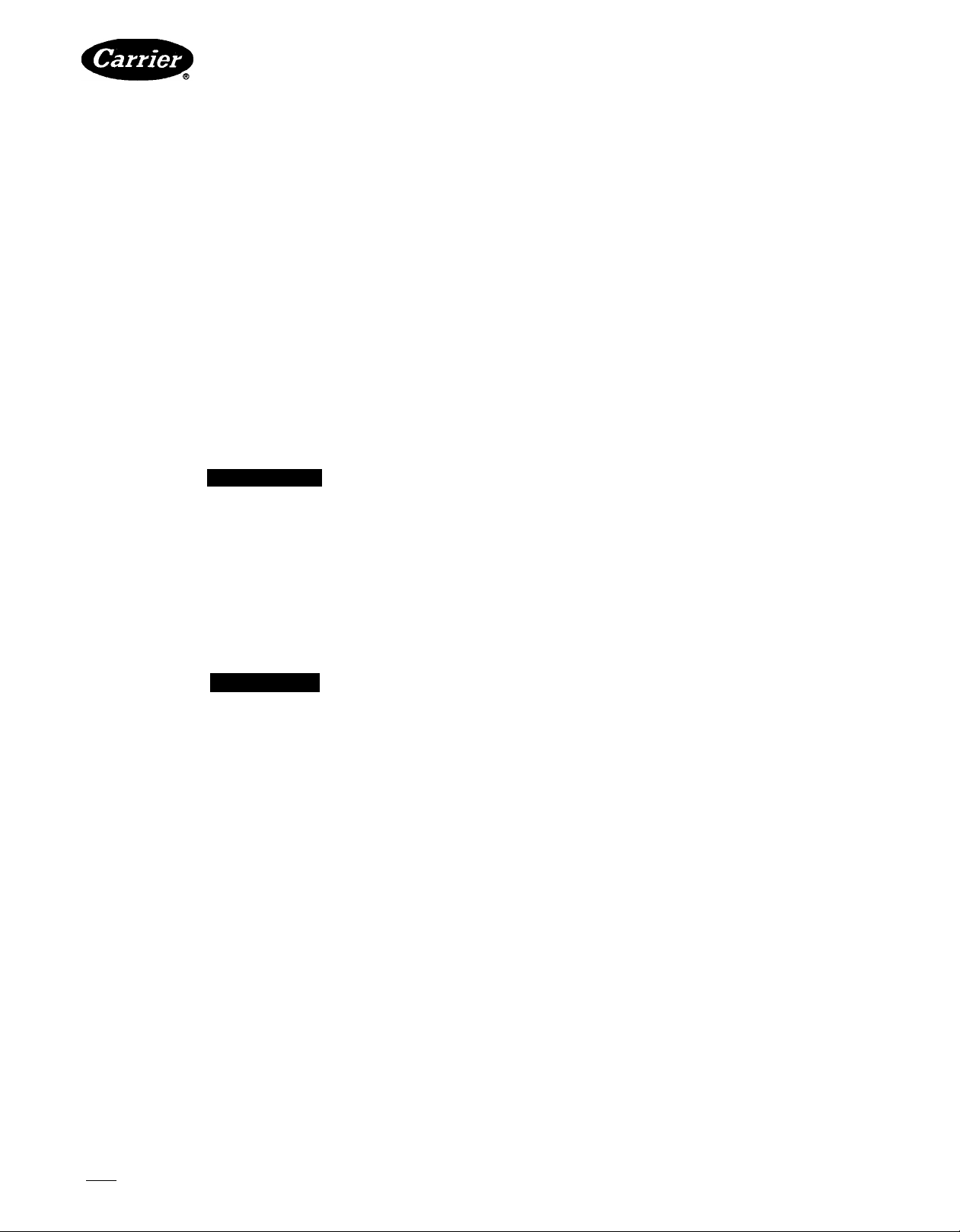
Furnaces in Confined Spaces (Typical Furnace
Closet)
ALL AIR FROM INSIDE BUILDINGS — The con
fined space shall be provided with 2 permanent openings,
one beginning within 12 in. of the top and one beginning
within 12 in. of the bottom of the enclosure. Each opening
shall have a minimum free area of one sq in. per 1000 Btuh
of the total input rating of all equipment in the enclo
sure, but not less than 100 sq inches. The openings must
freely communicate with other interior areas served by
the furnace, of sufficient volume so that the combined
volume of all spaces meets the criteria for an unconfined
space. This can be accomplished through either per
manent openings or louvered doors.
Furnaces in Unconfined Spaces (Basements,
Large Equipment Rooms, etc.) — If the uncon
fined space is within a building of unusually tight con
struction, air for combustion, ventilation and dilution of
flue gases shall be obtained from outdoors or from spaces
freely communicating with the outdoors. A permanent
opening, or openings, having a total free area of not less
than one sq in. per 5000 Btuh of total input rating for all
equipment shall be provided. A duct may be used to con
vey makeup air from the outdoors and shall be of the
same cross-sectional area as the free area of the openings
to which it connects. The duct may be connected to the
cold air return of the heating system only if it connects
directly to outside air. The minimum dimension of
rectangular air ducts shall be not less than 3 inches.
A CAUTION
Return air must not be taken from the room, unless
an equal or greater amount of air is supplied to the
room. All duct connections to the furnace must be
airtight to avoid causing a negative pressure condi
tion within the room.
Louvers and Grilles — In calculating the free area,
consideration shall be given to the blocking effect of
louvers, grilles, or screens protecting openings. Screens
used must not be smaller than 1 / 4-in. mesh. If the free
area through a design of louver or grille is known, it
should be used in calculating the size opening required to
provide the free area specified. If the design and free area
is not known, assume that wood louvers will have 20 to
25% free area and metal louvers and grilles will have
60 to 75% free area. Louvers and grilles that provide
combustion and dilution air must be constructed so they
cannot be closed.
©
Page 3
RETURN OR
SUPPLY AIR
pl~1
I I I
I I I
I I I
VENT TO ROOF
12 IN. MAX
I so IN. PER
2000 BTUH
DUCTS TO
OUTSIDE
I SO IN. PER
2000 BTUH
12 IN. MAX
±
T
I so IN. PER
4000 BTUH
DUCTS
TO ROOF
I I
I I
T
i
RETURN
OR
SUPPLY
AIR
VENT
TO ROOF
1 3
-12 IN.MAX
* MINIMUM OPENING SIZE IS 100 SO IN. (REUIRN
+ MINIMUMOF 3 IN. WHEN TYPE-BI VENT IS USED. AIR ONLY)
Fig. 1 — Upflow or Counterflow, Using Air
from Inside Building
GAS PIPING
Gas piping must be installed in accordance with
national and local codes.
The gas supply line should be a separate line directly
from the meter to the furnace, if possible. Referto Table 1
for recommended gas pipe sizing.
Table 1 — Maximum Capacity of Gas Pipe*
NOMINAL
IRON PIPE
SIZE
(in.)
'k
% 0.824
1 1.049
r/4
1V2
'Cubic ft of gas per hour for gas pressure of 0.5 psig or less, and a
pressure drop of 0.5 in wg (based on a 0 60 specific gravity)
Ref. Table C-4 NFPA 54-1984.
INTERNAL
DIAMETER
(in.)
0 622
1 380 1400 950
1 610 2100 1460 1180
LENGTH OF PIPE (ft)
10 20 30
175 120 97
360 250 200
680 465 375
40
50
82 73
170
151
285
320
770 660 580
990 900
RETURN OR
SUPPLY AIR
USE ANY OF THE FOLLOWING COMBINATIONS
OF OPENINGS; AaB CSD D8E
J
TO OUTSIDE
5
DUCT
I so IN. PER
4000 BTUH
Fig. 2 — Upflow or Counterflow, Using Air
from Outside Building
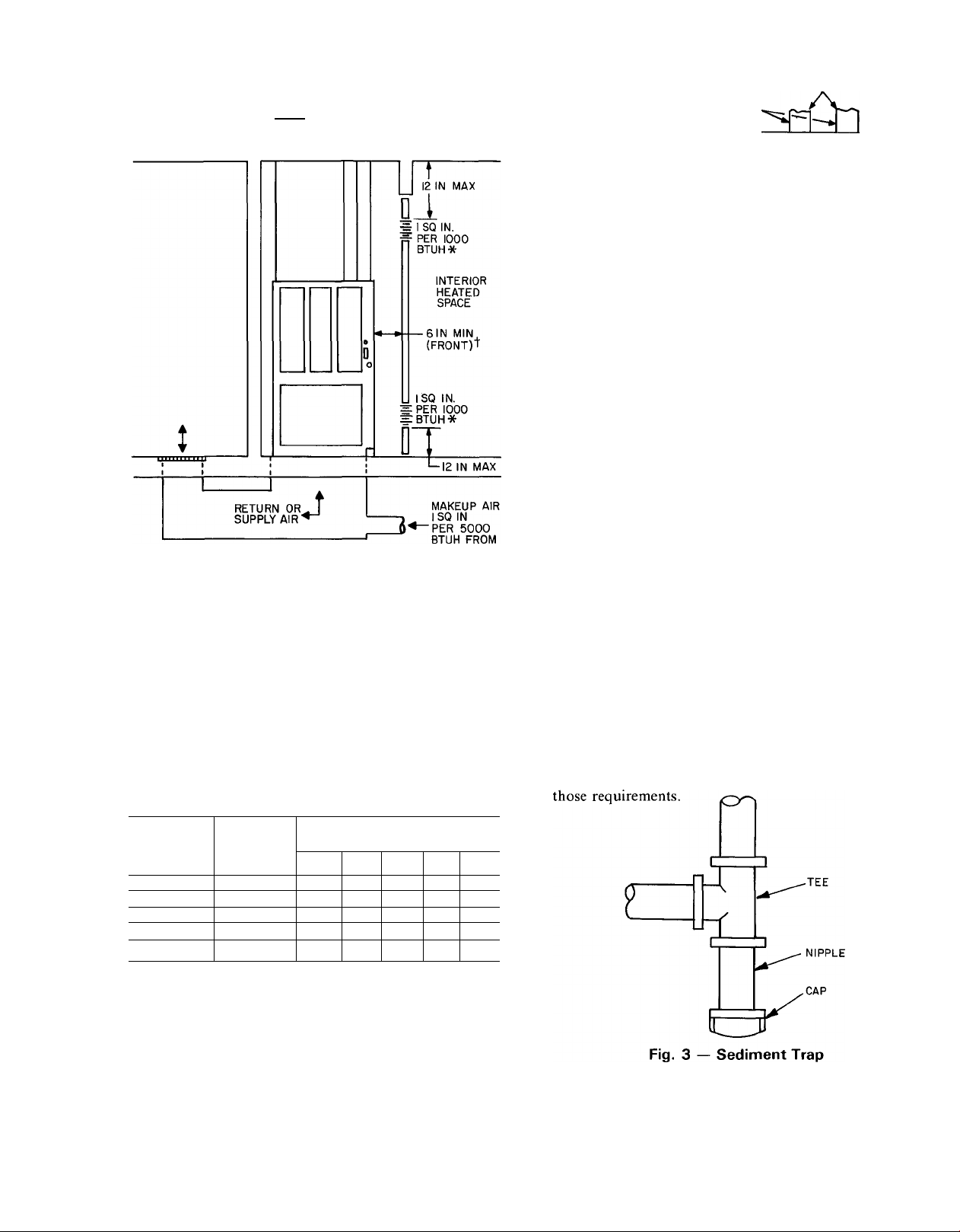
Install a sediment trap in the riser leading to the
furnace. This trap collects dirt or condensate. It can be
installed by connecting a Tee to the riser leading to the
furnace, so that the straight through section of the Tee
is vertical. Then connect a capped nipple into the lower
end of the Tee. The capped nipple should extend below
the level of the gas controls. See Fig. 3. Where a gum filter
is required by local codes, install it in accordance with
Avoid low spots in long runs of pipe. It is best to slope
all pipe I/4inch in 15 ft to prevent traps. All horizontal
runs should slope away from the meter, to risers. Risers
should be used to connect to the furnace and to the meter.
Joint compounds (pipe dope) should be applied
sparingly and only to the male threads of the joints.
Consult local supplier for type of compound to be used.
This pipe dope must be resistant to the action of LP
(propane) gas.
An accessible manual shutoff valve shall be installed
upstream of the furnace gas controls and within 6 ft of the
furnace. A 1/8-in. NPT plugged tapping, accessible for
test gage connection, must be installed immediately up
stream of the gas supply connection to the furnace, and
downstream of the manual shutoff valve.
Page 4

Place a ground joint union between the gas control
manifold and the manual gas shutoff valve. See Fig. 4.
A WARNING
Use the proper length of pipes to avoid stress on the
gas control manifold.
Protect all segments of the piping system against
physical and thermal damage. Support all piping with
appropriate straps, hangers, etc. Use a minimum of one
hanger every 6 feet. For pipe sizes larger than l/2in.,
follow recommendations of national codes.
A CAUTION
If a flexible connector is required or allowed by the
authority having jurisdiction, black iron pipe shall
be installed at the gas valve and extend a minimum of
2 in. outside the furnace casing.
point temperature. Do not attempt to confirm this data
by field measurement, as specific laboratory equipment
and test conditions are required.
Consult local codes. For additional information refer
to the National Fuel Gas Code (NFPA No. 54-1984 or
ANSI Z223.1-1984). Unless the local codes direct other
wise, unit may be vented to an NFPA-or ANSI-approved
chimney, or to a listed type-Bl gas vent. Connect the
vent collar to the chimney or gas vent to be used. Follow
these recommendations:
1. Select flue connection material that is satisfactory
for installation and that meets requirements of local
codes.
2. Flue connection pipe must be at least as large as
outlet collar on furnace. No reduction in this size is
permissible in pipe run.
NOTE: The clearance requirements which must be
maintained between the furnace vent pipe and com
bustible materials are as follows: 6 in. for single-wall
vent and one in. for type-Bl (double-wall) vent.
When B1 vent material is used, make the single wallto-B 1 transition with a listed transition fitting
directly on the flue collar or flue extension pipe.
3. Run pipe as directly as possible with minimum
number of turns and minimum of 12 in. straight pipe
before the first bend (upflow and downflow).
4. Maintain minimum of 1/4in. per linear ft upward
slope on all horizontal runs.
5. Rigidly support flue pipe with hangers and straps to
ensure that there will be no movement after
installation.
6. Insert smallest flue connection pipe at highest level
consistent with available headroom or clearance to
combustible materials, when 2 or more vent eon-
nectors enter a common gas vent or chimney flue.
7. Extend flue connection pipe through chimney wall
flush with inner face of chimney liner and above
extreme bottom to avoid restriction.
A WARNING
Piping should be pressure tested in accordance with
local and national plumbing and gas codes before furnace
has been attached. If pressure exceeds 0.5 psig(14in. wg),
gas supply pipe must be disconnected from furnaee before
pressure test. If test pressure is equal to or less than 0.5
psig (14 in. wg), close manual shutoff valve located on gas
valve before test. Ground joint union should be loosened
before pressure testing.
After all connections have been made, purge the lines
and check for leakage.
A WARNING
Never purge a line into a combustion chamber. Never
use matches, candles, flame, or other sources of
ignition for the purpose of checking leakage. Use a
soap-and-water solution to cheek for leakage.
VENTING
■ Venting Category I — This furnace complies with
Venting Category 1, as noted on the furnace rating plate.
This refers to the type of venting system as specified in the
ANSI 21.47 requirements, against which this appliance is
tested and design certified by the American Gas Associa
tion Laboratories. Specifically, Venting Category 1 is a
nonpositive venting system, meaning the static pressure
in the vent is less than atmospheric pressure, and the stack
gas temperature is at least 140 degrees F above the dew
Never connect into a chimney serving a fireplace
unless the fireplace opening is sealed off.
8. No portion of venting system shall extend into, or
pass through, any circulating air duct or plenum.
9. Chimney or gas vent shall extend at least 5 ft above
highest connected draft hood and should extend high
enough above roof or neighboring obstruction, so
that wind from any direction will not create positive
pressure in vicinity of chimney or gas vent outlet.
Chimney or gas vent should extend 3 ft higher than
point of emergence through roof, and at least 2 ft
higher than any object within a radius of 10 feet. See
Fig. 5.
A type-B 1 gas vent shall terminate above roof surface
10.
with a listed cap or roof assembly.
Common Venting with Other Appliances —
This furnace may be connected to a common chimney or
listed type-Bl gas vent with other listed gas-fired appli
ances. The vent system of this induced-draft furnace
operates at negative pressure during normal operation. If
for any reason the pressure in the vent system becomes
positive (may happen if chimney is inadvertently
blocked), the furnace shuts down and locks off. This is
accomplished by means of draft safeguard switch located
on tube attached to relief box just above draft inducer
blower. The design of this furnace, equipped with draft
safeguard switch, has been tested by the American Gas
Association Laboratories.
Page 5

MORE THAN
Fig. 5 — Chimney, Gas Vent Height
Type-BI Gas Vent — Note that this furnace may
be connected to type-Bl gas vents. Type-Bl vents are
suitable, providing the vent system always operates at
zero or negative pressure. The vent system of this furnace
meets this standard.
For Replacement Installations, Refer to
Appendix, page 7.
ELECTRICAL
IMPORTANT: Before proceeding with electrical
connections, make certain that voltage, frequency
and phase correspond to that specified on the furnace
rating plate. Also, check to be sure the service pro
vided by the utility is sufficient to handle the addi
tional load imposed by this equipment. Refer to unit
rating plate for equipment electrical requirements.
The specific furnace installation instructions contain
wiring diagrams which show the proper field high- and
low-voltage wiring. Make all connections in accordance
with National Electrical Code and any local codes or
ordinances that apply.
A WARNING
The cabinet must have an uninterrupted or unbroken
ground according to National Electrical Code,
ANSl/NFPA 70-1984 and local codes to minimize
personal injury if an electrical fault should occur.
Ground may be electrical wire or conduit, approved
for electrical ground when installed in accordance
with electrical codes. Do not use gas piping as
electrical ground.
START-UP, ADJUSTMENT, AND
SAFETY CHECK
Intermittent Ignition Systems — Check to be sure
all connections have been properly made, then proceed
as follows:
Light furnace, using the procedure outlined on the
lighting instruction plate attached to the furnace.
However, when lighting the pilot for the first time,
perform the following additional steps:
1. If supply line was not purged before connecting fur
nace, it will be full of air. It is recommended that the
ground joint union be loosened, and supply line be
allowed to purge until odor of gas is detected. Never
purge gas lines into a combustion chamber. Imme
diately upon detection of gas odor, retighten the
union. Allow 5 minutes to elapse, then light pilot in
accordance with instructions on furnace.
2. After pilot lights, main burners should light in
25-75 seconds. If main burners do not light within that
time period, adjust pilot flame, allow pilot to cool
for 5 minutes, repeat time check.
3. Locate pilot adjusting screw on top of gas valve.
a. Remove cap screw; turn pilot adjusting screw
counterclockwise to decrease burner-on time delay,
clockwise to increase burner-on time delay.
b. Replace cap screw.
Gas Input — Determine gas input as follows:
NATURAL GAS
a. Turn off all other gas appliances and pilots.
b. Measure time (in seconds) for gas meter test dial to
complete one revolution.
c. Refer to Table 2 for cu ft of gas per hour.
Multiply cu ft per hour times heating value of gas
d.
(Btu/cu ft). Obtain heating value of gas from local
utility.
Example:
Btuh heating input = Btu/cu ft x cu ft/hr
Heat value of gas = 1070 Btu/cu ft
Time for one revolution of 2 cu ft dial = 72 seconds
Gas rate = 100 cu ft/hr (from Table 2)
Btuh heating input = 1070 x 100 = 107,000 Btuh
Measured gas input should not exceed gas input
e.
shown on unit rating plate.
PILOT flame
BURNER FLAME
A CAUTION
If manual disconnect switch is to be mounted on
furnace, select a mounting location where drill or
fastener will not contact electrical or gas components.
NOTE: Use only copper wire between disconnect switch
and furnace.
Check all electrical connections (both factory and field)
for tightness. This should also be done after the unit has
reached operating temperatures, especially if aluminum
conductors are used.
Page 6

Table 2 — Gas Rate (Cu Ft Per Hr)
SECONDS
FOR ONE
REVOLU-
TION
10
11
12
13
14 257
15
16
17
18
19
20
21
22
23
24 150
25
26 138
27 133
28
29
30
31
32
33
34 106
35
36
37
38
39
40
41 88
42 86
43
44
45
46
47
48 75
49
SIZE OF
TEST DIAL
1 2
cu ft cu ft cu ft
720
360
327 655 1636 51
300 600 1500 52 69 138 346
555
277
514
240 480 1200 55
225 450 1125 56
424
212
200 400 1000 58
189 379 947 59
180 360 900 60 60
171 343 857 62 58
164 327 818 64 56 112
157 313 783 66
300 750 68 53 106 265
144 288
277 692 72
267 667 74
257 643
129
124 248 621 78 46
240 600 80 45
120
232
116
113 225 563
218
109
212
103 206
100 200 500 92 39 78
97 195 486 94 38 75 192
95 189 474 96 38 75 188
185
92
90 180 450 100 36 72 180
176
172
84 167
82 164
80 160
157
78
76 153
150
73 147
SECONDS
FOR ONE
REVOLU-
5
TION
1800 50
1385 53 68
1286
54 67 133 333
1059 57 63
720 70
76 47
581
545 86
529 88
514
82 44
84
90 40 80 200
462 98
439 102 35
429
419
409
400
391
383
375
367
104 35 69 173
106 34 68 170
108 33 67
110 33 65
112 32 64 161
116 31 62 155
120
SIZE OF
TEST DIAL
1
2
cuft cu ft
72 144 360
71
cu ft
141 355
136 340
131
65
64
129
126 316
62 124 310
61
122
120 300
116 290
54
109
51 103 257
100 250
50
97 243
48
95 237
92
80
78
76
43
75
42
74
41
37 74 184
71 178
60 150
30
5
327
321
305
281
273
231
225
220
214
209
205
196
167
164
f. To adjust input rate, remove cap that conceals regu
lator adjustment. Turn adjusting screw counterclock
wise (out) to decrease input When adjusting, DO
NOT change manifold pressure more than 0.3 in. wg.
Make any major adjustment by changing main burner
orifices.
HIGH ALTITUDE— Ratings are approved for altitudes
to 2000 ft for all gases. Ratings for altitudes over 2000 ft
are 4% less for each 1000 ft above sea level. (Furnace must
be derated by changing main burner orifices.)
BURNER AND PILOT FLAMES — The main burner
flame should be elear blue, almost transparent. The pilot
flame should be well defined. See Fig. 6.
Temperature Rise — Do not exceed the range of
temperature rise specified on the unit rating plate. Deter
mine the air temperature rise as follows:
1. Place duct thermometers in return and supply ducts
as near furnace as possible. Be sure thermometers do
not “see” heat element so that radiant heat will not
affect thermometer readings. This is partieularly
important with straight-run duets.
2. When thermometer readings stabilize, subtract returnair temperature from supply-air temperature to deter
mine air temperature rise.
3. Adjust air temperature rise by adjusting blower speed.
Increase blower speed to reduce temperature rise.
Decrease blower speed to increase temperature rise.
Thermostat Heat Anticipator Check — Thermo
stat heat anticipator must be set to match amp draw of
gas valve and eleetrical components in R-W circuit.
Accurate amp draw readings can be obtained at thermo
stat subbase terminals R & W. Figure 7 illustrates an easy
method of obtaining actual amp draw. Amp reading
should be taken after blower motor has started.
Fig. 7 — Amp Draw Check with Ammeter
Limit Control Safety Check — This control shuts
off the combustion control system and energizes the
circulating-air blower motor if the furnace overheats.
The recommended method of checking the limit con
trol is to gradually block off the return air after the
furnace has been operating for at least 5 minutes. As soon
as the limit has proven safe, the return air opening should
be unblocked to permit normal air circulation. By
using this method to check the limit control, it can be
established that the limit is functioning properly and will
“fail-safe” if there is a motor failure. The downflow/
horizontal furnaces have a manual reset limit switch
located on blower housing.
Flow-Sensing Switch Safety Check — This con
trol proves operation of the draft inducer blower. Check
as follows:
1. Turn off 115-volt power to furnace.
2. Remove control door and disconnect inducer motor
lead wires from inducer printed-circuit board.
3. Turn on 115-volt power to furnaee.
4. Close thermostat switch as if making a normal furnace
start. The pilot should light and then cycle off and on.
If main burners do not light, flow-sensing switch is
functioning properly.
5. Turn off 115-volt power to furnace.
6. Reconnect inducer motor wires, replace control door,
turn on 115-volt power.
Draft Safeguard Switch Safety Check — This
control permits safe shutdown of furnace during certain
blocked flue conditions. Check as follows:
1. Disconnect power to furnace and remove vent pipe
from furnace outlet collar. Allow time for vent pipe
to cool before removing.
2. Set room thermostat above room temperature and
restore power to furnace.
3. After normal start-up, allow furnace to operate 2
minutes. Block (100%) flue outlet. Furnace should
cycle off within 2 minutes.
4. Reeonneet vent pipe to furnaee outlet collar.
5. Wait 5 minutes. Reset draft safeguard switch.
Page 7

FURNACE LOCATION WITH RESPECT
TO COOLING EQUIPMENT
The cooling coil must be installed parallel with, or on
the downstream side of the furnace to avoid condensa
tion in the heating element. When installed parallel with a
furnace, dampers or other means used to control the flow
of air must prevent chilled air from entering the unit.
If the dampers are manually operated, they must be
equipped with means to prevent operation of either unit
unless the damper is in the full-heat or full-cool position.
APPENDIX —
Venting Replacement Installations
SPECIAL LOCATIONS
When the furnace is installed in a residential garage,
burners and ignition source should be no less than 18 in.
above the floor. Furnace should be protected against
physical damage by vehicles.
When the furnace is installed in public garages, air
plane hangars, or other buildings having hazardous
atmospheres, it should be installed in accordance with
recommended good practice requirements of the National
Fire Protection Association.
1. The vent is a critical part of the heating system. It
should always be examined prior to installation of
the furnace.
II. When installing high-efficiency furnaces on a venting
system that is “marginal,” the following suggestions
may help;
A. Set furnace to full input rate. New furnaces are
commonly set conservatively at factory.
Existing Chimney
Type-BI Vents
Existing Chimney
Masonry Chimney
B. Minimize restrictions in vent connector — use as
few elbows as possible.
C. Insulate any long horizontal single-wall vent
connector with 1/2-in. insulation or use double
wall pipe.
D. Follow recommendations in flow charts regarding
application of 58SC, SS, DH induced-draft fur
naces on existing chimney.
Existing Chimney
Masonry Chimney — Tile Liner
Page 8

58SS/DH
HEATING A COOLING
Induced-Combustion Gas-Fired Furnaces
Manufacturer reserves the right to discontinue, or change at any time, specifications or designs without notice and without incurring obligations.
Book|l PC 101 Catalog No 515-808 Printed in USA Form 58D,S-2XA Pg 8 6-85 Replaces: 58D,S-1XA
Tab l6a
 Loading...