

Carrier Corporation • Syracuse. N.Y. 13221
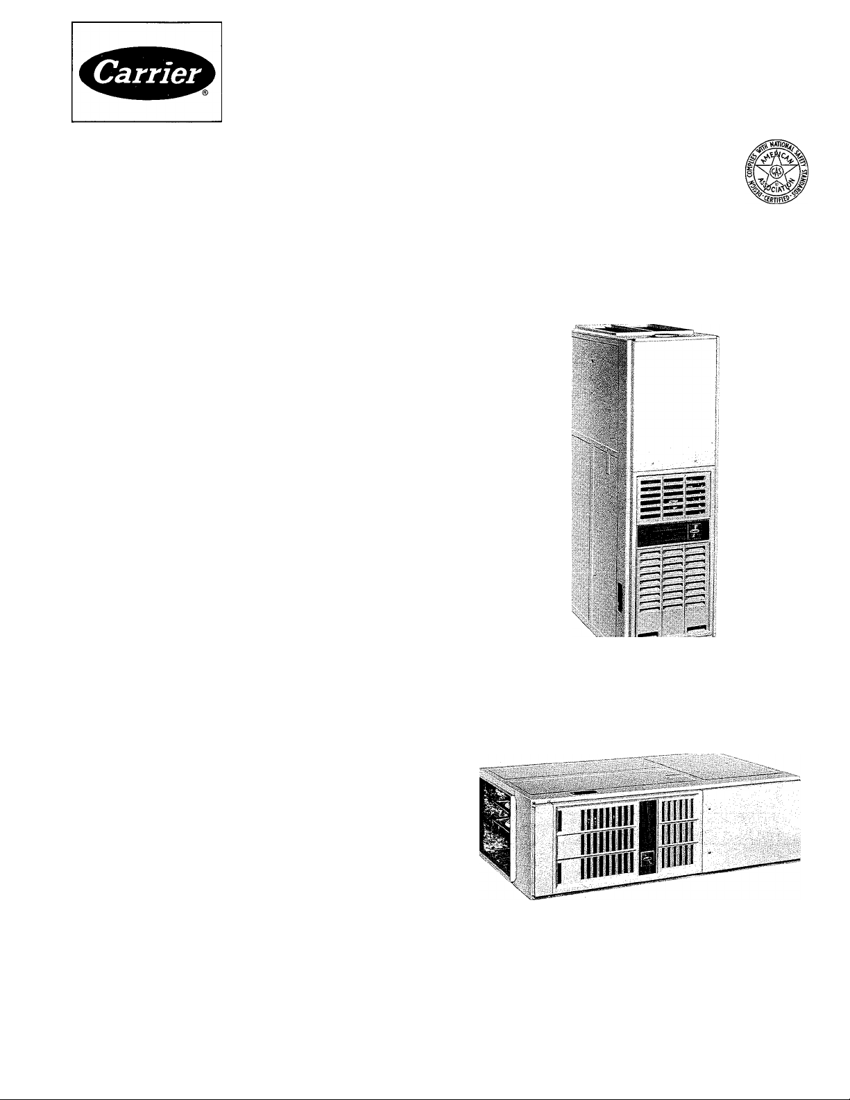
Downflow/Horizontal Induced-Draft
Gas Furnace
GENERAL
Before starting installation of this furnace, read
these instructions carefully and completely. After
installation is complete, remove the Energy Guide
tag from the furnace. Also read the Procedures for
Induced-Draft Gas-Fired Furnaces (packaged with
furnace) for important information concerning
combustion, venting, piping and other standard
installation practices. Further reference can be made
to the current edition of the American National
Standard Z223.1 National Fuel Gas Code.
The induced-draft vent system of this furnace is
designed to operate at zero or negative pressure at
the vent connector outlet. This furnace, therefore,
complies with the National Fuel Gas Code (NFPA
54-1980 or ANSI Z223.1-1980), Part 7.14.3.b. This
furnace is also listed by AGA for use with the type
B1 gas vent, as described in the National Fuel Gas
Code, Part 7.3.2.
Each furnace is shipped from the factory com
pletely assembled with multispeed direct-drive
blower, and wired ready for indoor heating installa
tion. All sizes feature a blower control center with
easy-to-read low-voltage terminal strip to ensure
proper connections.
The output capacity and any representations of
efficiency for this product are based on standard
Department of Energy test procedures. The installed
operation may vary, depending on installation,
weather and other factors.
EPFICIENCY
RATING
CERTIFIED
a
Fig. 1 — Furnace in Downflow Position
ama
( \l NON Ddik'I II Mall liiinaCL
^l^.c III i.iiiilaminali.d atmnMilu n. Xdlicu lo.ill
combustion and ciiculatmg air requirements
listed in Procedures foi Induced-Dratt (iasI ii..d liiiiiai.is ()h'^eI\l. all loi.al Lodes and
1 1 1
a >.ono
Fig. 2 — Furnace in Horizontal Position
The design of the downflow/horizontal (Fig. 1
and 2) gas-fired furnace is AGA certified for in
stallation on combustible flooring (with optional
floor base), in alcoves, attics, crawl spaces, base-
Carrier Corporation 1984 Form 58DH-3SI
ments, closets or utility rooms. The design of this
furnace line is not AGA certified for installation in
mobile homes, recreation vehicles or outdoors.
-H THERMOSTAT „„
S
WIRE ENTRY 13..
-2l
o
.. f
_ _
-4"
llll
’ j
1" 7“
“'2
S POWER
ENTRY
F"
H
1
■
r
_ _
Ì
l^DIA KO.
RH.GAS
ENTRY
M
► ---i"
=^ORI
BOLTS (BOTH SIDES)
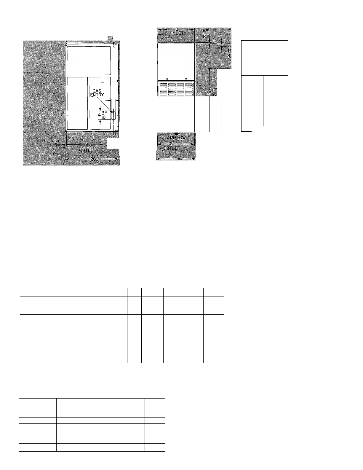
Fig. 3 — Dimensional Drawing (in.)
Installation Procedures
Page
1
**
*
*
*
SIDESt
1
0 0
Iti
lit
nt
nt
ut
BACK
0
0 18
0 18
3 6
3 3
0 18
Horizontal Attic Installation...................................4
Crawl Space Installation
Filter Arrangement ............................................... 5
Electrical Connections
Sequence of Operation
Start-Up and Adjustment
Care and Maintenance ...........................................8
*Provide a 30-in. service clearance in front of
FRONT VENT
6»*
3»*
1
6
1
6
1
1
6
the furnace.
flndicates supply or return sides \A/hen furnace
is in the horizontal position.
íFor installation on non-combustiblefloorsonly.
For installation on combustible flooring only
when installed on special base (Part No.
58DS900041).
**Alcove installations require 18-in. front
clearance.
ttLine contact permissible only between lines
formed by intersections of the top and 2 sides
of the furnace jacket, and building joists, studs
or framing.
ifClearance shown is for the outlet side. The inlet
side must maintain 6-in. clearance from flue
to combustible materials with single-wall vent.
Inspection
........................................................
Location, Ventilation and Air for
Combustion
Gas Piping
.....................................................
...........................................................
Venting ................................................................ *
Supply-Air Plenum Installation
(downflow) ...................................................... 3
‘Refer to appropriate sections of ProcSdures for Induced-Draft Gas-Fired Furnaces booklet packed with this furnace.
Table 1 — Clearances (in.)^
FURNACE
DOWNFLOW (In Alcove or Closet)|
Single-Wall Vent 1
Type B1 Double-Wall Vent
HORIZONTAL (In Alcove)ft
Single-Wall Vent 1
Type B1 Double-Wall Vent 0
HORIZONTAL (In Closet)
Single-Wall Vent 2
Type B1 Double-Wall Vent 2
HORIZONTAL (Attic or Unoccupied Spaces)
Type B1 or Type L Double-Wall Vent
TOP
1
.......................................
.........................................
.........................................
......................................
Page
5
5
V
8
Table 2 — Dimensions (in.)
Furnace
Size
035,040
055,060
070,080
090,1 OO(CC) 17-1/2
090,1 OO(DC) 21
110,120 24-1 /2
A
14-3/16
14-3/16
17-1/2
B
12-9/16
12-9/16 12-11/16 4
15-7/8 16
15-7/8 16i 4
19-3/8 19-1/2 4
22-13/16 23 5
C
12-11/16 4
Vent
Diam
NOI I \Mn.i' l)4().i)SS ,|iul iibli size )m-
n.iccN .ih. iiiM.iILd in d hoii/iMiul poMiion on
conibiixliblc ni,iîi.iial 11 IS iictcss.ii\ lo i.iisciIil
I LI I IKK I. OIK in lo ohi.iin icqiiiicd (<-in \Liiipipc
lIc.LI.1IKl tOI
.1
Mllglc V^dll Lent
The Carrier induced-draft gas furnace is designed
4
to accept a Carrier electronic air cleaner and
humidifier.
For accessory installation details, refer to appli
cable installation literature.
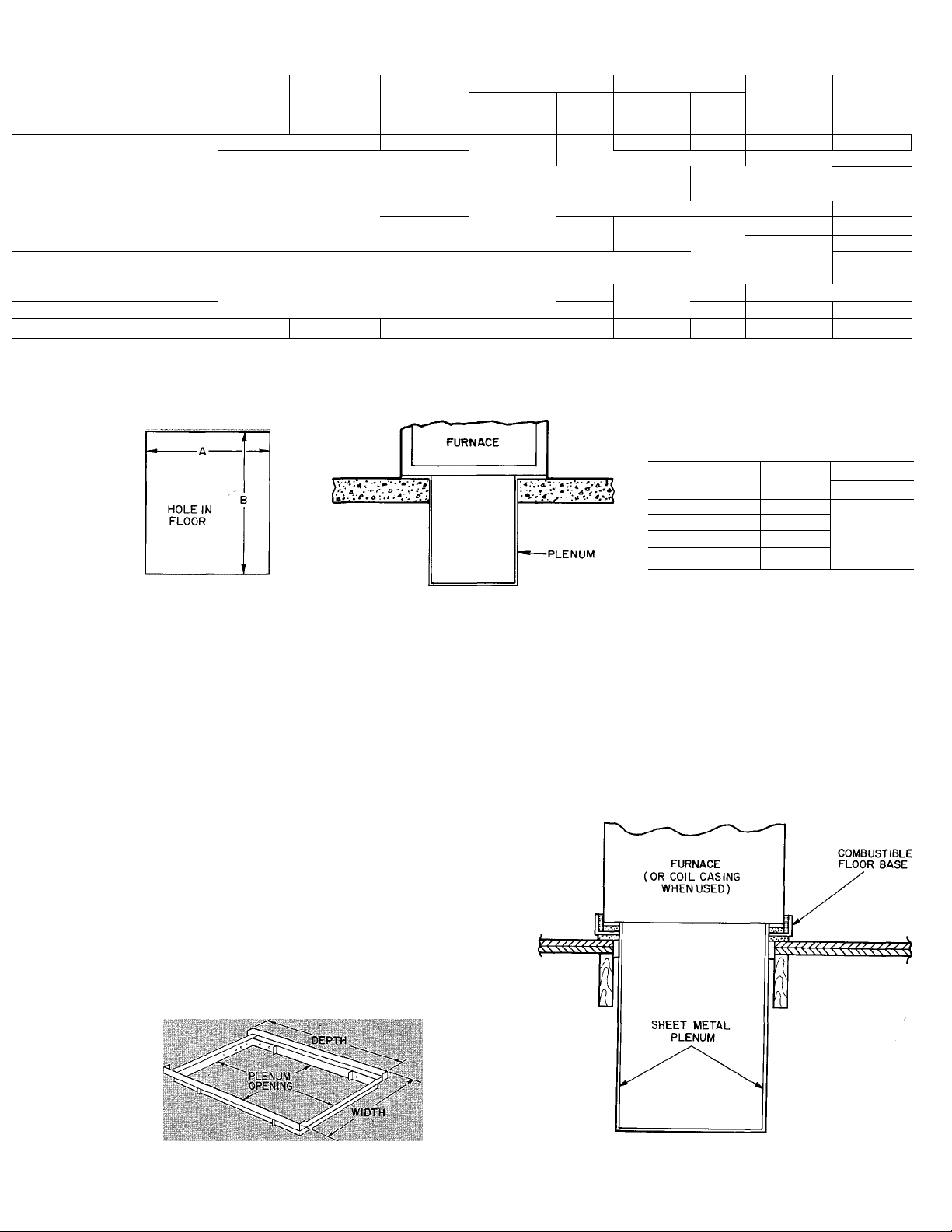
Table 3 — Ratings and Performance*
FURNACE
SIZE
OJS 100CC
040-100CC 48,000 38,000
055-1OOCC ; 6.1,UCiO
beo-'iooc'c i /1000
070-1 OOCC f 86,OCiO 71 000
080-1 OOCC 95,000 77,000
OiJO loncr
1 100 1 OOCC
OOlllOODC 107,000
100-100DC 119,000
^ iio-ii)ocf;
120-1 OOCC 143,000 117,000
. ' I r. Models meet or exceed California low NOx requirements.
PSC — Permanent Split Capacitor
*Ratings are certified for altitudes to 2000feet. For elevations above 2000ft, reduce ratings 4% for each 1000ft above sea level.
tOetermined by U.S. Government Standard test procedures using outdoor combustion air method.
INPUT
(Btuh)
43,000
107,000
119,000 98,000
■ ■ )bo"'
CAPACITY
(Btuht)
3b,000
52,000
57,000 \ 45-75
88,000 ¡ 55-85
88,000 50 80
97,000
106,000
TEMP
RISE
RANGE (F)
20- 50
25-55 .12
•10 7(J 012
40-70 015
45-75 0.15
60-90 _!20 I 1348
3-85
40 '7Ó
50-80
HEATING COOLING
Ext Static
Pressure
(in. wg)
0 12
0 12
0.20
0 2n
0 20 193/
0.20" 1937
Cfm
1060 0 50
1060 0.50
1080
1080
1240 0 50 ' 1553
1240
0 20 ! 1348 0 50
13i)0
1350 0.50 1929 1/2PSC 188
Ext Static
Pressure
(in. wg)
0.50
0.50
0.50 1553
0.50 1590 1 2 PSC
0 50
0 50 2010
0.50
Table 4 — Opening Dimensions
MOTOR
Cfm
1 171
11/1 1 /3 PSC
1157 1 3PSC
1157 1 3PSC
1590 1 2 PSC
1929 ! 1 2PSC 188
2010 1/2PSC 208
HP & TYPE
1 '3PSC
1 2 PSC
1/2PSC
1 2PsSC 208
APPROX
SHIP.
WT (lb)
132
132
142
142
163
16.1
178
178
(in.)
Fig. 4 — Floor Opening
for Concrete Slab
Fig. 5 — Furnace on a Concrete
Slab
INSTALLATION
Supply-Air Plenum (Downflow)
INSTALLATION ON CONCRETE SLAB
1. See Fig. 3 for dimensions and location of supplyair opening in furnace bottom.
2. Construct hole in floor. See Fig. 4 and Table 4.
3. Place plenum and furnace. See Fig. 5.
INSTALLATION ON COMBUSTIBLE FLOOR
1. Read installation instructions packaged with
accessory combustible floor base.
2. Cut and frame hole in floor. See Table 1 of in
stallation instructions packaged with combus
tible floor base. If this requires cutting a floor
Furnace
Size
035—060
070—lOO(CC)
090—100(00
110—120 23-7/16
13-1/8
16-7/16
19-7/8
A
B
Heat-Only
19-5/8
joist, tie ends of cut joist into adjacent joists for
proper floor support.
3. Assemble and install combustible floor base per
instructions packaged with base.
4. When completed, install combustible floor base,
plenum, and furnace (or coil casing when used).
See Fig. 7.
Fig. 6 — Accessory Combustible Floor Base
Fig. 7 — Furnace, Plenum, and
Base Installed on Combustible Floor
 Loading...