

Page 1

HEATING & COOUNG
Upflow/Horizontal Oil Furnace
Installation, Start-up and Operating Instructions
FOR YOUR SAFETY
DO NOT STORE OR USE GASOLINE OR OTHER FLAMMABLE
VAPORS AND LIQUIDS IN THE VICINITY OF THIS OR ANY OTHER
APPLIANCE.
DO NOT ATTEMPT TO START THE BURNER WHEN EXCESS OIL HAS
ACCUMULATED, WHEN THE FURNACE IS FULL OF VAPOR OR WHEN
THE COMBUSTION CHAMBER IS VERY HOT.
58BTA
WARNING
For use with grade 2 Fuel Oil maximum. Do Not
use Gasoline, Crankcase Oil or any Oil containing
Gasoline!
CAUTION
Never burn garbage or paper in the heating systems
and never leave rags or paper around the unit.
CAUTION
These instructions are intended to be used by
qualified personnel who have been trained in
installing this type of furnace. Installation of this
furnace by an unqualified person may lead to
equipment damage and/or a hazardous condition
which may lead to bodily harm.
GENERAL
This furnace is a three position unit, in that it may be
operated in upflow, horizontal left-to-right, and horizontal
right-to-left air flow positions. Very few modifications are
required to change the furnace from one position to
another at the job site. The furnace is shipped in the
upflow configuration-instructions on changing to other
configurations are on page 6 of this document.
It is shipped as a packaged unit, complete with burner
and controls. It requires a line voltage (115VAC)
connection to the control box, a thermostat hook-up as
shown on the wiring diagram, oil line connection(s),
adequate ductwork, and connection to a properly sized
vent.
The air handling capacity of this furnace is designed for
cooling air flow. Refer to Figure 6 for the expected
airflows at various external duct static pressures.
Manufacturer reserves the right to discontinue, or change at any time, specifications or designs without notice and without incurring obligations.
Book 14' PC 101
Tab 6a 8a
Catalog No. 565-878
Printed in U.S.A. Form 58BTA-1SI
Issue 9413
20142901 118
Replaces; New
Page 2

IMPORTANT: All local and national code requirements
governing the installation of oil burning equipment, wiring
and flue connections must be followed. Some of the
codes (issued by the Canadian Standards Association,
the National Fire Protection Agency, and/or the American
National Standards Institute) that may be applicable are:
CSA B139
ANSI/NFPA 31
ANSI/NFPA 90B WARM AIR HEATING AND AIR
ANSI/NFPA 211
ANSI/NFPA 70
CSA C22.1
Only the latest issues of the above codes should be used,
and are available from either:
The National Fire Protection Agency
Batterymarch Park
Qunicy, MA 02269
INSTALLATION CODE FOR OIL
BURNING EQUIPMENT
INSTALLATION OF OIL BURNING
EQUIPMENT
CONDITIONING SYSTEMS
CHIMNEYS, FIREPLACES, VENTS
AND SOLID FUEL BURNING
APPLIANCES
NATIONAL ELECTRICAL CODE
CANADIAN ELECTRICAL CODE
attic instailation. As this unit may be installed as an
upflow or horizontal furnace, it may be located in a
basement, on the same level as the area to be heated,
suspended, or in a crawlspace. In any case, the unit
should always be installed level.
In a basement, or when installed on the floor (as in a
crawlspace), it is recommended that the unit be installed
on a concrete pad that is 1" to 2" thick.
When installed in a horizontal position, the furnace may
be suspended by using an angle iron frame, as long as
the total weight of both the furnace and the frame are
allowed for in the support calculations. (Other methods of
suspending are acceptable.)
The required minimum clearances for this furnace in all
positions are specified in Figure 5.
The furnace should be located as close as possible to the
chimney or vent in order to keep vent connections short
and direct. The furnace should also be located as near
as possible to the center of the air distribution system.
or The Canadian Standards Association
178 Rexdale Blvd.
Rexdale, Ontario M9W 1R3
LOCATION
WARNING
This furnace is not watertight and is not designed for
outdoor installation. This furnace shall be installed
in such a manner as to protect the electrical
components from water. Outdoor installation would
lead to a hazardous electrical condition and to
premature furnace failure.
CAUTION
For an attic installation it is important to keep
insulation 12" or more away from any furnace
openings. Some types of insulating materials may
be combustible.
Air for Combustion and Ventilation:
This furnace should be installed in a location in which the
facilities for ventilation permit satisfactory combustion of
oil, proper venting and the maintenance of ambient
temperature at safe limits under normal conditions of use.
The location should not interfere with proper circulation of
air within the confined space.
In addition to air needed for combustion, process air shall
be provided as required for: cooling of equipment or
material, controlling dew point, heating, drying, oxidation
or dilution, safety exhaust and odor control.
In addition to air needed for combustion, air shall be
supplied for ventilation, including all air required for
comfort and proper working conditions for personnel.
The barometric draft regulator, included with the furnace,
shall be installed in the same room or enclosure as the
furnace in such a manner as to prevent any difference in
pressure between the regulator and the combustion air
supply.
Air requirements for the operation of exhaust fans, kitchen
ventilation systems, clothes dryers, and fireplaces shall be
considered in determining the adequacy of a space to
provide combustion air requirements.
This furnace is approved for reduced clearances to
combustible construction, therefore, it may be installed in
an alcove or similar enclosure. It is also approved for
Issue 9413
20142901 218
Page 3

In unconfined spaces in buildings of conventional frame,
brick or stone construction infiltration may be adequate to
provide air for combustion, ventilation and dilution of flue
/--xgases. This determination must be made on an individual
( hstallation basis and must take into consideration the
overall volume of the unconfined space, the number of
windows and ventilation openings, the number of doors to
the outside, internal doors which can close off the
unconfined space and the overall tightness of the building
construction.
Many new buildings and homes (and older ones that have
been weatherized) must be considered as being tight
construction and, therefore, infiltration will not be sufficient
to supply the necessary air for combustion and ventilation.
A building can be considered as being of tight
construction when:
a. Walls and ceilings exposed to the outside
atmosphere have a continuous water vapor
retarder with a rating of one perm or less with
openings gasketed or sealed and /or
b. Weatherstripping has been added on operable
windows and doors, and/or
c. Caulking or sealants are applied to areas such as
joints around window and door frames, between
sole plates and floors, between wall-ceiling joints,
between wall panels, at penetrations for
plumbing, electrical and fuel lines and at other
openings.
If combustion and ventilation air must be supplied to an
unconfined space from outside, an opening with a free
area of not less than one square inch per 1,000 BTU per
hour of total input of all appliances within the unconfined
space (but not less than 100 square inches) must be
provided. This opening must be located such that it can
not be blocked at any time.
When ducts are used to supply air, they must be of the
same cross sectional area as the free area of the
openings to which they connect.
The minimum dimension of rectangular air ducts must not
be less than 3 inches.
In calculating free area, consideration shall be given to
the blocking effect of louvers, grilles or screens protecting
openings. Screens used shall not be smaller than 1/4
inch mesh and shall be readily accessible for cleaning.
If the free area through a design of louvered or grille is
known, it shall be used in calculating the size design and
free area specified. If the design and free area is not
known, it may be assumed that wood louvers will have 20
percent free area and metal louvers and grilles will have
60 percent free area. Louvers shall be fixed in the open
position or interlocked with the furnace so they are
opened automatically at furnace start-up and remain open
during furnace operation.
WARNING
Do not block the combustion air openings in the
furnace. Any blockage will result in improper
combustion and may result in a fire hazard and/or
cause bodily harm.
Ductwork Recommendations:
The proper sizing of warm air ducts is necessary to insure
satisfactory furnace operation. Ductwork should be in
accordance with the latest editions of NFPA-90A
(Installation of Air Conditioning and Ventilating Systems)
and NFPA-90B (Warm Air Heating and Air Conditioning
Systems) or Canadian equivalent.
For a confined space, where air is taken from an interior
space, two permanent openings of equal area are
required. One opening must be within 12" of the ceiling
and the other within 12" of the floor. Each opening must
have a free area of at least 1 sq. inch per 1,000 BTU of
total input rating but no less than 100 sq. inches.
If outside air is supplied to a confined space, then the two
openings must be equal and located as above and the
free area of each must be:
1. 1 sq. inch per 4,000 BTU of total rating when the
air is directly communicated from the outdoors.
2. 1 sq. inch per 4,000 BTU of total input rating
\ when the air is brought in through vertical ducts.
3. 1 sq. inch per 2,000 BTU of total input rating
when the air is transferred through horizontal
ducts.
The supply ductwork should be attached to the flanged
opening provided at the discharge end of the furnace.
See Figure 7 for the dimensions of this opening.
Knockouts are provided on both sides of the furnace to
facilitate the side panel cut out required to assemble the
return ductwork. This can be done on either the right or
the left side of the furnace. See Figure 7 for location and
dimensions. Undersized cut-outs will adversely affect the
airflow capability of the furnace.
When the provided external filter rack is used, the return
air duct should be attached as per Figure 9.
Provision is also made on this furnace for a bottom return
air duct. (We recommend the use of this opening for
horizontal installations.) The specifications for this
ISSUE 9413
20142901 318
Page 4

opening are also illustrated in Figure 7. If the bottom
return is not used, a field-supplied galvanized steel filler
plate should be used to block off the opening.
The following recommendations should be followed when
installing the ductwork:
1. Install locking type dampers in ail branches of the
individual ducts to balance out the system.
Dampers should be adjusted to impose the
proper static at the outlet of the furnace.
2. A flexible duct connector of noncombustible
material should be installed at the unit on both
the supply and return air system. In applications
where extremely quiet operation is necessary, the
first 10 feet (if possible) of supply and return
ducts should be internally lined with acoustical
material.
WARNING
The coil MUST be installed on the air discharge side
of the furnace. Under no circumstances should the air
flow be such that cooled, conditioned air can pass
over the furnace heat exchanger. This will cause
condensation in the heat exchanger and possible
failure of the heat exchanger which could lead to a fire
hazard and/or a hazardous condition which may lead
to bodily harm. Heat exchanger failure due to
improper installation may not be covered by warranty.
2. In parallel flow installation, dampers must be
provided to direct air over the furnace heat
exchanger when heat is desired and over the
cooling coil when cooling is desired.
3. In cases where the return air grille is located
close to the fan inlet, there should be at least one
90° air turn between fan inlet and grille. Further
reduction in sound level can be accomplished by
installing acoustical air turning vanes or lining
duct as described in item 2 above.
4. When a single air grille is used, the duct between
grille and furnace must be the same size as
return opening in furnace.
CAUTION
Return air grilles and warm air registers must not be
obstructed.
WARNING
When supply ducts carry air circulated by the furnace
to areas outside the spaces containing the furnace,
the return air shall also be handled by a duct sealed to
the furnace casing and terminating outside the space
containing the furnace. Incorrect ductwork termination
and sealing will create a hazardous condition which
could lead to bodily harm.
IMPORTANT: The dampers should be adequate to
prevent cooled air from entering the
furnace, and if manually operated,
must be equipped with the means to
prevent operation of either the
cooling unit or furnace unless the
damper is in the full cool or heat
position.
Venting Instructions:
Venting of the furnace should be to the outside and in
accordance with local codes or requirements of the local
utility.
OIL FIRED APPLIANCES SHALL BE CONNECTED TO
FLUES HAVING SUFFICIENT DRAFT AT ALL TIMES
TO ENSURE SAFE AND PROPER OPERATION OF
APPLIANCE.
For additional venting information refer to ANSI/NFPA 211
Chimney. Fireplaces. Vents and Solid Fuel Burning
Appliances and/or CSA B139 Installation Code.
When installing the furnace with cooling equipment for
year round operation, the following recommendations
must be followed for series or parallel air flow:
1. In series air flow applications, the coil is mounted
after the furnace in an enclosure in the supply air
stream. The furnace blower is used for both
heating and cooling air flow.
This furnace is certified for use with Type "L" vent
(maximum flue gas temperature 575°F).
ISSUE 9413
20142901 418
Page 5

Pre-Installation Vent System Inspection:
Before this furnace is installed, it is highly recommended
;"^^that any existing vent system be completely inspected.
For any chimney or vent, this should include the following:
1. Inspection for any deterioration in the chimney or
vent. If deterioration is discovered, the chimney
must be repaired or the vent must be replaced.
2. Inspection to ascertain that the vent system is
clear and free of obstructions. Any blockage
must be cleared before installing this furnace.
3. Cleaning the chimney or vent if previously used
for venting a solid fuel burning appliance or
fireplace.
4. Confirming that all unused chimney or vent
connections are properly sealed.
5. Verification that the chimney is properly lined and
sized per the applicable codes. (Refer to list of
codes on page 2.)
Masonry Chimney:
This furnace can be vented into an existing masonry
chimney. This furnace must not be vented into a chimney
servicing a solid fuel burning appliance. Before venting
) this furnace into a chimney, the chimney must be checked
for deterioration and repaired if necessary. The chimney
must be properly lined and sized per local or national
codes.
If the furnace is vented into a common chimney, the
chimney must be of sufficient area to accommodate the
total flue products of all appliances vented into the
chimney.
The following requirements are provided for a safe venting
system:
the highest point where it passes through a roof
of a building and at least two (2) feet higher than
any portion of a building within a horizontal
distance of ten (10) feet. It shall also be
extended at least five (5) feet above the highest
connected equipment flue collar.
10. Check local codes for any variance.
Factory Built Chimneys:
May use listed factory built chimneys. Refer to chimney
manufacturers instructions for proper installation.
Horizontal Venting ”150 Size Only"!:
This furnace may be horizontally vented through an
outside wall when installed with the following auxiliary
inducer blower:
Tjernlund Products, Inc. Model SS1C
available from:
Tjernlund Products, Inc.
1601 Ninth Street
\A/hite Bear Lake, MN 55110-6795
NOTE: An isolation relay should be used to allow proper
operation of the ignition control with the auxiliary
blower. Instructions for connecting the relay are
included in the Tjernlund blower.
CAUTION
USE METALLIC VENT PIPE, ONLY! PLASTIC VENTING MATERIALS ARE PROHIBITED!
1. Be sure that the chimney flue is clear of any dirt
or debris.
2. Be sure that the chimney is not servicing an open
fireplace.
3. Never reduce the pipe size below the size of the
furnace flue pipe.
4. All pipe should be supported using the proper
clamps and/or straps. These supports should be
at least every four (4) feet.
5. All horizontal runs of pipe should have at least a
1/4" per foot of upward slope.
6. All runs of pipe should be as short as possible
with as few turns as possible.
7. Seams should be tightly joined and checked for
leaks.
8. The flue pipe must not extend into the chimney
but be flush with the inside wall.
9. The chimney must extend three (3) feet above
Oil Burner:
This furnace is supplied with a high pressure atomizing
retention head type burner (for use with not heavier than
grade 2 Fuel Oil). The air tube length, from the face of
the mounting plate to the extreme face of the end cone,
should be seven (7) inches.
Lubricate the burner motor with SAE 10 oil. Once each
year, pour two (2) teaspoons of oil slovviy into each oil
cup.
ISSUE 9413
20142901 518
Page 6
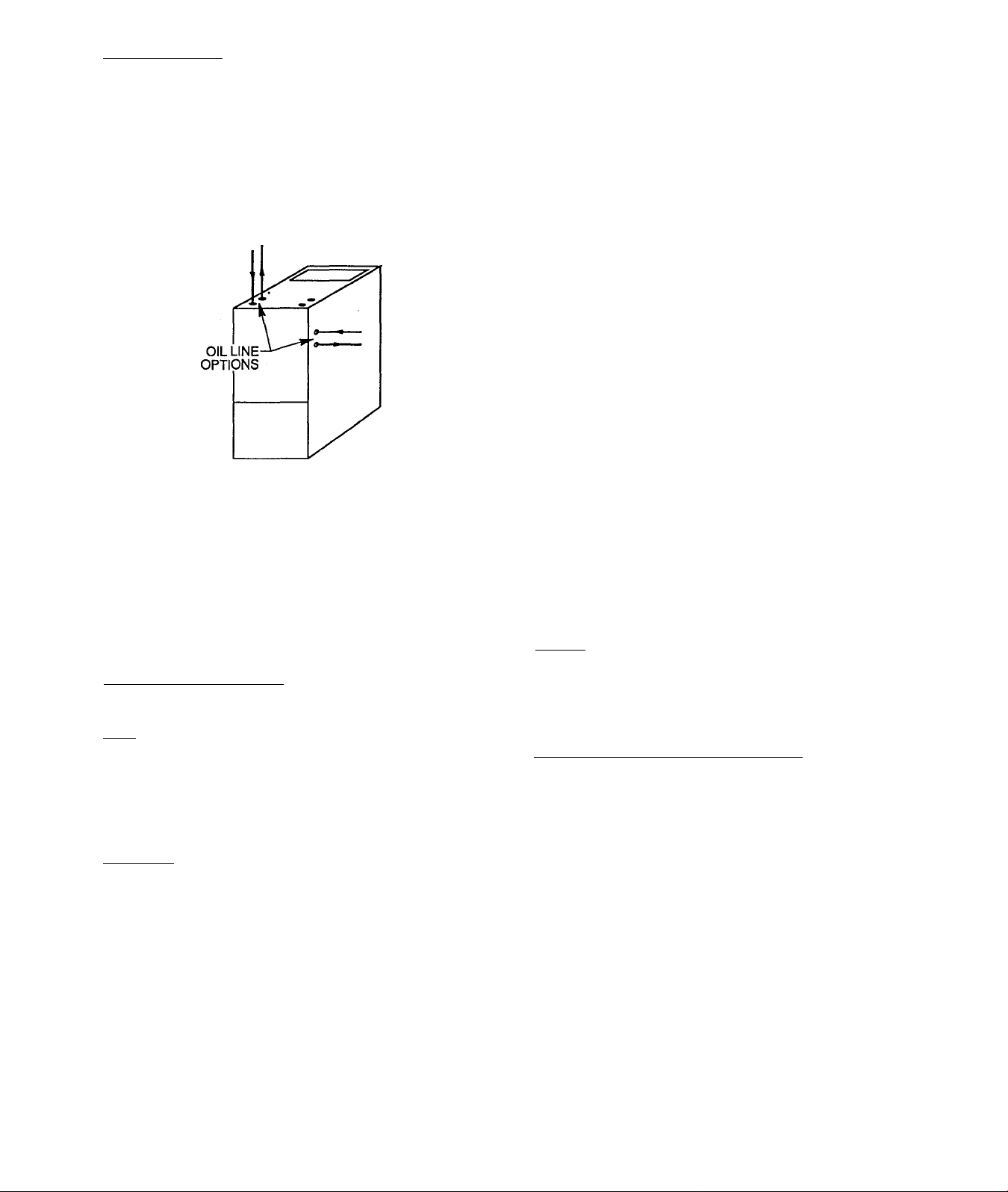
Oil Connections:
Complete instructions for installation of the fuel oil piping
will be found in the oil burner installation instructions
included with the furnace.
Oil line entry holes are produced in the side panels and
top panel. Two holes are provided in each location, so
that a two-pipe system may be used if desired. See
Figure 1 below.
Oil Connection Entry Holes
Figure 1
An oil filter should be used with all oil burners, installed as
close as possible to the burner.
WARNING
TTie unit cabinet must have an uninterrupted or
unbroken electrical ground to minimize personal injury
if an electrical fault should occur. A green ground
screw is provided in the control box for this
connection.
Use copper wire only for 115V supply service to unit.
Metallic conduit (where required/used) may terminate at
the side panel of the unit. It is not necessary to extend
the conduit inside the unit from the side panel to the
control box.
When replacing any original furnace wiring, use only 105
degree C, 16 AWG copper wire.
Instructions for wiring the thermostat are packed in the
thermostat (field supplied) box. Make the thermostat
connections as shown in Figure 10 at the 24 volt terminal
board on the control box.
When installing optional accessories to this appliance,
follow the manufacturer's installation instructions included
with the accessory. Other than wiring for the thermostat,
wire with a minimum of type "T" insulation (63°F rise)
must be used for accessories.
Barometric Draft Control:
The barometric draft control shipped with the furnace
must be used with the furnace to insure proper operation.
Instructions for installing the control are packed with the
control. Refer also to Figure 8 on page 14 for suggested
locations.
Electrical:
The appliance must be installed In accordance with
current ANSI/NFPA 70 National Electrical Code, CSA
C22.1 Canadian Electrical Code Part 1 and/or local
codes.
The control system depends on the correct polarity of the
power supply. Connect "HOP' wire (H) and "NEUTRAL"
wire (N) as shown in Figure 10.
A separate line voltage supply should be used with a
fused disconnect switch or circuit breaker between the
main power panel and the unit. See Figure 10.
Filters:
An external filter rack is provided as standard equipment
with this furnace. The assembly and installation of this
filter rack is shown in Figure 9.
To Change from Upflow to Horizontal:
• Remove the burner from the unit by removing the
three burner mounting nuts. Prevent putting
undue strain on burner wiring. (It may be
necessary to disconnect the burner wiring in
some cases.)
Note that the three burner mounting studs are in
the "nine, twelve, and three" o'clock positions on
the burner mounting plate.
Place the furnace in the installation position (i.e.,
on its side). Remove the burner mounting stud
that is now in the six o’clock position (See
Illustrations A & B). Reinstall the stud in the
other open position on the mounting plate, so that
ISSUE 9413
20142901 618
Page 7

once again there are studs in the nine, tweive,
and three o'clock positions. It may be necessary
to use two of the burner mounting nuts as "Jam
"N Nuts" on the stud in order to provide a means of
y using a wrench to remove a tight stud.
• Reinstall the burner, insuring that all three burner
mounting nuts are tight. IMPORTANT: Burner
must always be installed in the upright position
with the ignition control on top.
START-UP:
1. Check the wiring against the diagram in Figure
10.
2. Open the valve on the oil supply line.
3. Reset the primary control.
4. Set the thermostat above room temperature.
5. Set the main electrical switch to "ON" position
and the burner should start.
DO NOT TAMPER WITH THE UNIT OR CONTROLS CALL YOUR SERVICEMAN.
(ILLUSTRATIONS A & B)
WARNING
Do not use this furnace as a construction heater. Use
of this furnace as a construction heater exposes the
furnace to abnormal conditions, contaminated
combustion air and the lack of air filters. Failure to
follow this warning can lead to premature furnace
failure and/or vent failure which couid result in a fire
hazard and/or bodily harm.
WARNING
Installation of this furnace in an area where it will
receive contaminated combustion air must be avoided.
Such contamination would include the following:
ammonia, chlorine, hydrogen sulfide, halogenated
hydrocarbons, carbon tetrachloride, cleaning solvents,
hydrochloric acid, water softening chemicals and other
similar chemicals. Failure to follow this warning will
lead to premature rusting of the heat exchanger and
possible premature furnace failure and/or vent failure
which couid result in a fire hazard and/or bodily harm.
Operational Checkout:
DO NOT START THE BURNER UNLESS THE BLOWER
ACCESS DOOR IS SECURED IN PLACE.
Recommended Installation
Practices and
Combustion Check:
In order to obtain the optimum performance from the oil
burner, the following set-up procedures must be
followed:
1. A test kit (Bacharach No. 5022 kit or equivalent)
to measure the smoke, stack draft, over-fire
draft, COj, and stack temperatures must be
used in order to obtain the proper air band
setting. Although all of the above
measurements are required for optimum set up
and efficiency data, the most important readings
that must be taken are the smoke number, over
the fire draft and stack draft.
2. The proper smoke number has been
established by engineering tests to be between
0 & 1. This degree of smoke emission is
commonly referred to as a "Trace" of smoke. It
is recommended to use a Bacharach true spot
smoke test set or equivalent.
3. In order to ensure the proper draft through the
furnace, a barometric draft regulator, which is
supplied with the furnace, must be installed as
close to the outlet of the furnace as possible.
In order for this device to function properly, the
barometric damper must be mounted with the
hinge pins horizontal and the face of the
damper vertical (see instructions included with
damper). The draft regulator should be
adjusted after the furnace has been firing for
at least five minutes and the stack draft should
be measured and set between -.025" wc and
-.035"wc. The draft should be checked with a
Bacharach MZF draft gauge or equivalent.
The installation of the furnace is now complete and the
operational checkout may be performed.
ISSUE 9413
20142901 718
Page 8

4. The over the fire draft, which is taken through
the hole that is provided in the observation
door, is a measurement that is necessary to
determine if there is a blockage between the oil
burner and the flue outlet.
There should be between a .005"wc to .020"wc
pressure drop through the furnace. This would
set the range of the over the fire draft between
-.01 "wc to -.03"wc. A reading above -.01 "wc,
for example +0.1 "wc, would indicate that the
furnace is in an extremely high pressure
condition in the primary section. This condition
may be caused by excessive combustion air
due to the air band being too wide open or a
lack of flue draft (chimney effect) or some other
blockage, such as soot, in the secondary
section of the heat exchanger.
5. The CO2 and stack temperature instruments will
enable you to obtain the data that is required to
determine the thermal efficiency of the furnace.
Although this information is nice to have, it is
not essential in the basic set up of the furnace.
6. An oil filter should be installed as close to the
burner as possible with ail oil
burners and is essential on the lower firing rate
burners. We recommend the use of a low
pressure drop oil filter such as the General
Filter, Inc . model #1A-25A or equivalent. It is
critical that the oil capacity be equivalent or
greater than the fuel pump gear capacity. For a
two pipe system this is 25gph.
7. The oil pressure regulator is factory set to give
nozzle oil pressures of 100PS1G. The firing
rate noted on the nameplate may be obtained
with "standard" nozzles by adjusting the pump
pressure as noted on the chart below or noted
on the label on the furnace.
NOTE: This appliance is equipped with one of the
oil burners as listed on the chart below and rating
label on the furnace. Use the nozzle listed for that
specific oil burner.
On a new installation the air entrapped in the oil
line leading from the tank to the nozzle must be
thoroughly purged in order to prevent excessive
after drip. The oil pump is provided with a
special fitting that will enable you to purge any
air between the tank and oil pump. The proper
procedure for performing this operation is as
follows:
Place a piece of clear plastic 1/4" dia. tubing
over the purge fitting on the oii pump. Start the
oil burner, then open the purge fitting and allow
the burner to run until the purge tube is
completely free of air bubbles. At this point
tighten the purge fitting which will allow the oil
to run to the nozzle and fire the burner. (If the
purging takes longer than 15 seconds and no
flame has been established the burner will stop.
Push the reset button on top of Primary Control
to restart burner.) For detailed information on
operation of primary control refer to instructions
included with furnace.
8. After all the set up procedures mentioned
above have been completed, the burner should
be allowed to operate and an inspection mirror
should be used to observe the flame pattern.
Any irregularities such as burning to one side or
pulsating flame patterns should be corrected by
changing the nozzle.
BURNER, NOZZLE AND PUMP PRESSURE CHART
HEATING
CAPACITY
BTU/HR.
150,000 1.35
200,000 1.75
FIRING
RATE
GAL/HR/(US)
PUMP
PSIG
100
100
Fan Adjustment Check:
This furnace is equipped with a 3 speed direct drive
motor to deliver a temperature rise within the range
specified on the rating plate, between the return and
supply plenums, at the external duct static pressure
noted on the rating label.
DUCANE
OIL BURNER
MODEL NOZZLE
DRC-20A 1.35 GPH
DRC-20A 1.75 GPH
80* SOLID
80" SOLID
Adjust the fan speed so that the temperature rise is
within the rise specified on the rating plate. Consult the
wiring diagram for speed changes on the direct drive
motor.
To adjust fan OFF time, set the DIP switches on the
control board as shown to obtain the desired timing
(See Figure 2 on next page).
MODEL
AFG
AFG
R.W.
OIL
BECKETT
BURNER
1.35 GPH
70* SOLID
1.75 GPH
70’ SOLID
NOZZLE
ISSUE 9413
20142901 818
Page 9

MAINTENANCE
This furnace should never be operated without an air
filter. Filters should be cleaned at least twice a year.
Figure 2
Limit Control Check:
After the furnace has been in operation for at least 15
minutes, restrict the return air suppiy by blocking the
filters or closing the return registers and allow the
furnace to shut down on high limit. The burner will shut
OFF and the main blower should continue to run.
Remove the restriction and the burner should come
back on in a few minutes.
For Year Round Air Conditioning;
The furnace is designed for use in conjunction with
cooling equipment to provide year round air
conditioning. The blower has been sized for both
heating and cooling, however, the fan motor speed may
need'to be changed to obtain the necessary cooling air
flow.
Heating:
The blower speed is factory set to deliver the required
air flow at normal duct static pressure.
Cooling:
The blower speed may be adjusted in the field to
deliver the required air flow, for cooling application, as
outlined in Figure 6.
To avoid personal injury, make sure the electrical
supply power is "OFF" before servicing.
ALWAYS KEEP THE MAIN OIL VALVE TURNED
OFF, IF THE BURNER IS SHUT DOWN FOR AN
EXTENDED PERIOD OF TIME.
WARNING
Before performing any service functions, unless
operations specifically require the power to be on,
make sure ail utilities are turned "OFF" upstream of
the appliance. Failure to comply with this warning
will cause a fire hazard and/or bodily harm.
Periodic oiling of the blower motor may be necessary.
Check for instructions on the inside of your blower
compartment door.
To maintain proper performance, the oil burner nozzle
must be replaced once a year. Contact your dealer
serviceman if you are unsure of this procedure.
The procedure for nozzle installation and/or
replacement is outlined in the oil burner instruction
manual which came with the furnace. For ease of
maintenance, the oiling procedure for the burner motor,
as outlined in the burner manual, should be performed
at this time.
After replacement of the nozzle, the burner should be
adjusted in accordance with the "COMBUSTION
CHECK" section of the instruction.
Ordinarily, it is not necessary to clean the heat
exchanger or flue pipe every year, but it is necessary to
have your oil burner serviceman check the unit before
each heating season to determine whether cleaning or
replacement of parts is required.
Constant Blower Switch:
This furnace is equipped with a constant iow speed
blower option. Whenever the room thermostat is not
calling for heating or cooling, the blower will run on low
speed in order to provide air circuiation. If this constant
blower option is not desired, the rocker switch on the
side of the controi box may be used to "turn off" the
constant speed.
If cleaning is necessary, the following steps should be
performed:
1. Turn "OFF" all utilities upstream of the furnace.
2. Disconnect the flue pipe.
3. Remove the collar on the flue connection.
ISSUE 9413
20142901 918
Page 10

4. Remove the upper rear panel.
5. Remove the flue collector box from the
secondary heat exchanger tube flange. This
exposes the inside surfaces of the secondary
tubes of the heat exchanger. If only the
secondary needs to be cleaned, no further
disassembly is required.
13. Again, use a stiff brush and vacuum cleaner to
clean the inside of the primary drum.
CAUTION
Never use incendiary type cleaners (smoke sticks)
for cleaning!!
6. Clean the secondary tubes and flue pipe with a
stiff brush and vacuum cleaner.
If the primary heat exchanger section is also to be
cleaned;
7. Disconnect the limit control wires
8. Disconnect the oil line and remove the oil
burner from the furnace.
9. Remove the observation door.
10. Remove the collar on the observation tube.
11. Remove the intermediate panel. (Care, must be
taken not to bend or damage the limit control.)
12. Loosen to hand tightness the three (3) nuts
labeled "A" in Figure 3. Remove the screws
labeled "B" in Figure 3. Slide the combustion
chamber forward, out of the heat exchanger.
Be careful not to bump the combustion
chamber as it becomes brittle after having been
fired.
14. Before reassembly, the heat exchanger and
combustion chamber should be inspected to
determine if replacement is required. After
cleaning, place combustion chamber back into
primary drum and secure with the "B" screwsinsure that the cover plate gasket is in place
before tightening the screws. (Care must be
taken not to damage the combustion chamber.)
15. Tighten the "A" nuts to 30 pound-inches of
torque (firm, but not overly tight).
16. Replace the intermediate panel, observation
tube collar, observation door, limit wiring, and
oil burner.
17. Replace the collector box on the secondary
tube flange, insuring proper placement of the
gasket. If gasket is damaged in any way, it
should be replaced! Tighten the screws to 30
pound-inches of torque.
18. Replace the upper rear panel and flue collar.
19. Reconnect the flue pipe and oil pipe(s).
Figure 3
20. Readjust burner for proper operation. Check
limit operation as outlined in this manual.
COMBUSTION CHAMBER REMOVAL
ISSUE 9413
20142901 1018
Page 11

Figure 4
BLOWER REMOVAL
REMOVE 3 SCREWS
Blower Removal (Refer to Figure 4):
1
To remove the blower from the furnace:
1. Turn "OFF" all utilities upstream of the furnace.
2. Remove the louvered door and blower door.
3. Remove the blower retaining screw (on the
blower partition panel, near the corner where
the intermediate panel and blower partition
meet).
4. Remove cover from control box and disconnect
the thermostat and power wires from the board.
5. Remove the three (3) screws holding control
box to the blower partition.
6. Slide the blower forward on the rails toward the
front of the unit until the motor wire connections
at the terminal block on the motor can be easily
reached and disconnected.
7. Disconnect the motor wires at the terminal
block on the motor and then disconnect the two
(2) red wires connected to the auxiliary limit
control mounted on the opposite side of the
blower.
8. Swing control box out of the way of the blower
and remove blower from unit.
CAUTION
Be sure the blower is adequately supported when
sliding out of the mounting rails, especially in the
horizontal position, in order to prevent dropping the
ibiower and injuring yourself or damaging the blower!
9. Reverse the above steps to reinstall the blower.
(Refer to wiring diagram Figure 10 of this
instruction or the diagram located on the inside
of the door to properly rewire the unit.)
ISSUE 9413
20142901 1118
Page 12

MINIMUM CLEARANCE TO COMBUSTIBLES
(Adequate service clearance should be provided over and above these dimensions, as required.)
CLEARANCE FROM : UPFLOW
Top of furnace casing or plenum 2"
Top of horizontal warm-air duct within 6 ft of furnace
Flue pipe, measured horizontally or below pipe 9" 9"
Flue pipe, measured vertioally above pipe 9" 9"
Any side of supply plenum and warm-air duct within 6 ft of furnace
Front of furnace
Sides of furnace
Rear of furnace
Bottom of furnace
2" 3"
1" 1"
24"
2"
2"
0"* 0"*
HORIZONTAL
2"
24"
2"
2"
Floor may be combustible
Figure 5
WARNING
When operating the furnace in the heating mode, the static pressure and the temperature rise (supply air
temperature minus return air temperature) must be within those limits specified on the rating label. Failure to follow
this warning could lead to severe furnace damage.
UNIT OUTPUT
(KBTUH)
150 and 200
(12 X 12 WHEEL)
(3/4 HP MOTOR)
NOTES:
AIR-FLOW DATA
BLOWER
SPEED
LOW
MED
HIGH
0.1
0.2
1640 1590
2195
2485
2125
2395
0.3
1540 1515
2060
2305 2250
1) . AIR FLOW VALUES IN CUBIC FEET PER MINUTE (CFM), ROUNDED TO NEAREST FIVE (5) CFM
2) . DATA TAKEN WITHOUT FILTERS IN PLACE
EXTERNAL STATIC
0.4 0.5
1460
1990
1915
2145
Figure 6
0.6
1410
1860
2075
0.7
1350
1785
0.8 0.9
1275 1190
1700
1975 1885
1620 1525
1780
Issue 9413
20142901 1218
1.0
1075
1675
Page 13

GENERAL LAYOUT MULTI-POISE OIL FURNACE
■FLUE 6 0 FOR 150
FLUE 7 0 FOR 200
Figure 7
UP FLOT
GENERAL LAYOUT 150/200 MULTI-POISE OIL FURNACE
Issue 9413
20074701 1318
Page 14

BAROMETRIC DAMPER LOCATIONS
GOOD LOCATIONS
Figure 8
F
WRONG
BAD LOCATIONS
FIG. L
'POOR
ISSUE 9413
20142901 1418
Page 15

Filters
A filter and filter rack is supplied with the furnace.
It is NECESSARY THAT ALL FURNACES BE
EQUIPPED WITH A FILTER.
)
When filter rack is used on side of furnace:
1. Filter rack may be mounted on either side of
furnace.
2. The filter rack is made up of four (4) pieces - a top
and bottom (which are the same), and the rear and
access panels (which are the same). (Use the
shorter two rear/acess panels-discard the long
pair.)
clearance holes in the filter rack top, bottom, and
rear panels. DO NOT SCREW THE ACCESS
PANEL IN PLACE!
4. To fasten return air duct to filter rack, first cut a
notch in the return air duct (for filter access panel)
to dimension shown in detail. Then slide duct over
filter rack.
5. Remove access panel, slide filter in piace, then
replace access panel.
Minimum filter size and suggested filter material:
(If different type filter is used, it must be an equivalent
high airflow capacity.) 38'/4' X 24/i'
3. Using corner indentations as a guide, cut out the
selected side duct return opening (See Figure 7).
4. Clip the filter rack pieces together, as shown in
Figure 9.
5. Remove the rear-most sheet metal screw
(approximately 10" from the front of the unit) from
the base. Align the second hole from the front of
the filter rack bottom piece with the base hole and
reinsert the screw. (The frame should be centered
over the knockout opening.)
6. Hold the filter rack against the unit (make sure it is
; square) and drill the remaining holes in the side of
the unit located according to the clearance holes in
the filter rack top, bottom, and rear panels. DO
NOT SCREW THE ACCESS PANEL IN PLACE!
7. To fasten return air duct to filter rack, first cut a
notch in the return air duct (for filter access panel)
to dimension shown in detail. Then slide duct over
filter rack.
8. Remove metal rod from filter. Trim 4W' from width
of filter (24Vf to 20VJ'). Reinsert rod into filter at an
angle, so that it does not extend past sides of filter.
9. Remove access panel, slide filter in place, then
replace access panel.
When filter rack is used on return air End opening
of furnace (either upflow, or horizontal):
massmWi
(VASHASie
• rUMAMDCr
«Ncaf MO o€ .
iAirm* rtAiS
WARNING
Never operate unit without a filter or with filter
access door removed. Failure to adhere to this
warning could lead to a hazardous condition which
could lead to equipment damage and bodily harm.
Keeping Filters Clean
As a homeowner, this is your most important
responsibility. A dirty filter reduces the efficiency of
your system, causes erratic performance of controls
and could result is damage to the motor or heating
element.
1. Inspect filters at regular intervals
depending upon dirt conditions. For
new homes, check filters every week
for 4 consecutive weeks. In all cases,
inspect your filters at least every 3 to 4
weeks when the system is in constant
operation. Replace or clean filter at
least at the beginning of each season
(heating and cooling) and thereafter as
needed.
1. Clip the filter rack pieces together, as shown above.
(Use the longer two rear/acess panels-discard the
shorter pair.)
2. Position the rack centered over the opening in the
supply end of the furnace, with access panel toward
; front of unit.
3. Hold the filter rack against the end of the unit
(make sure it is square) and drill the mounting
holes in the end of the unit according to the
2. If the permanent filter supplied with the
filter rack becomes dirty, it can be
cleaned with cold water and soap.
Be sure that the filter is thoroughly dry before
installing back into the .furnace.
ISSUE 9413
20142901 1518
Page 16

FILTER RACK ARRANGEMENT INSTALLATION
Figure 9
FILTER RACK INSTALLATION
HORIZONTAL
FILTER RACK INSTALLATION
UPFLOW
Issue 9413
20142901 1618
Page 17

и Z
O'
I ^
'^Figure
Issue 9413
20142901 1718
Page 18

USER'S INFORMATION
Here's How Your Heating System Works
The furnace operates automatically. It is controlled
by a thermostat which you set at the temperature most
comfortable to you. When the inside temperature drops
below this setting, your thermostat will turn on the
heating system.
When the thermostat calls for heat, power from the
transformer energizes the fan control board. The fan
control energizes the ignition control. The ignition
control will light the burner automatically.
The electronic fan control will automatically turn on
the blower after 30 seconds. Fan "ON" control is not
adjustable. The air moved over the heat exchanger by
the blower is warmed and passes through the ducts to
the room registers.
When the thermostat is satisfied, the circuit is de
energized and the primary control shuts off the burner.
The blower continues to run until the selectable fan off
time period has expired.
The heat sensing switch performs as the furnace
high temperature limit switch. If the furnace overheats
for any reason, the limit switch opens, breaking the
circuit to the burner. The blower motor will be
energized and as the unit cools the limit switch will
close. This will relight the burner and unless the
overheating condition is corrected, the furnace will cycle
on limit.
This unit is equipped with an interrupted ignition
electronic control. If the main burner does not ignite
within 15 seconds from the call for heat, the conirol will
go into lockout. The red button on top of the control
must be depressed for 3 seconds in order to reset the
control. The control can not be reset from the room
thermostat.
1. Open all warm air registers and make sure that all
return air grills are unobstructed.
2. If a humidifier is installed with your system, open
the water supply valve.
3. Set the thermostat to its lowest setting.
4. Turn "ON" the electric power to the furnace.
5. Open the oil supply valve.
6. Check all connections to insure there are no leaks.
Lighting Your Furnace
CAUTION
This furnace is equipped with an interrupted type
electronic ignition system. DO NOT ATTEMPT TO
LIGHT WITH A MATCH. DANGER! HIGH
VOLTAGE AT IGNITOR.
1. This appliance is equipped with an ignition device
which automatically lights the burner. Do not try to
light the burner by hand.
2. After preparing the furnace for heating operation
(See previous section) and checking for oil, proceed
as follows.
3. For heating/cooling system, set the thermostat
system switch to "HEAT" and the fan switch to
"AUTO". Set the thermostat to the desired room
temperature and turn on the electrical power to the
furnace.
4. The burner should light and the system should be
controlled by the thermostat.
HEATING
Preparing Furnace For Operation
Before attempting to put your furnace into operation
for the heating season you should perform the following
procedures.
WARNING
If you do not follow these instructions exactly, a fire
or explosion may result causing property damage,
personal injury or. loss of life.
FOR SERVICE CALL
NAME:
ADDRESS:
TELEPHONE:
Turn Off Furnace
Follow these simple procedures to put your furnace
into "retirement" for the summer.
1. Set the thermostat to the lowest setting
2. Turn "OFF" all electric power to the appliance.
3. Turn the oil supply "OFF".
4. If applicable, turn "OFF" water supply to humidifier.
5. If furnace blower will be necessary for cooling
system, remember to turn electric power back on
when needed for air conditioning.
Issue 9413
20142901 1818
Page 19

Page 20

Copyright 1994 CARRIER Corp. • 7310 W. Morris St. ■ Indianapolis, IN 46231
Manufacturer reserves the right to discontinue, or change at any time, specifications or designs without notice and without incurring obligations.
Book 1 4
Tab 6a 8a
PC 101 Catalog No. 565-878 Printed in U.S.A.
Form 58BTA-1SI
Pg 20
Replaces: New
 Loading...