

Page 1
58ED,PB
HEATING A COOLING
Horizontal Gas-Fired Furnaces
Installation, Start-Up and Service Instructions
CONTENTS
Page
SAFETY CONSIDERATIONS
GENERAL .................................................................1
INSTALLATION ....................................................2-13
Step 1 — Select Location ...........................................2
Step 2 — Provide Air For Combustion and
Ventilation..............................................................3
Step 3 — Assemble Furnace ......................................3
• DRAFT HOOD
Step 4 — Size Ductwork
Step 5 — Vent Furnace ..............................................4
• MASONRY CHIMNEY
• TYPE B-1 VENT
• ATTIC INSTALLATION
Step 6 — Connect Gas Piping
• BURNER ORIFICES
Step 7 — Make Electrical Connections
Step 8 — Install Filters
.............................................
Step 9 — Reverse Components
(if required) ........................................................ 11-13
START-UP AND ADJUSTMENT ........................13-15
SERVICE AND MAINTENANCE
SAFETY CONSIDERATIONS
These instructions are intended for use by qualified
personnel who have been trained in installing this type of
furnace. Installation of this furnace by an unqualified
person may lead to equipment damage and/or a
hazardous condition which may lead to personal injury
GENERAL
This furnace is designed for use with either natural or
liquefied petroleum (propane) gases and has been design
certified by the American Gas Association It is shipped
as a packaged unit, complete with burners and controls,
and requires only a line voltage ( 115-v) connection to the
................................
...........................................
...................................
.....................
.......................
1
4
5
6
II
15-17
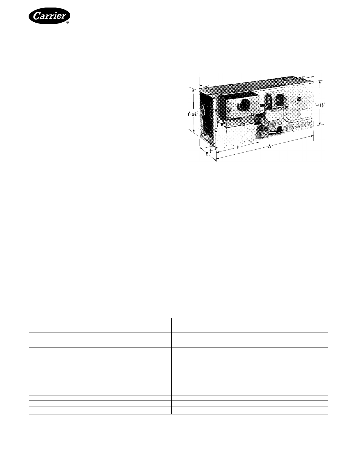
Fig. 1 — Furnace Dimensions
(Modei 58ED Shown)
junction box and a thermostat hookup as shown in the
wiring diagram. The design of the furnace is such that
the burners, controls and flue outlet can be assembled
on the same side to facilitate servicing for installations
where only limited access to the unit is available. (See
Step 9 — Reverse Components.) The 58ED furnace
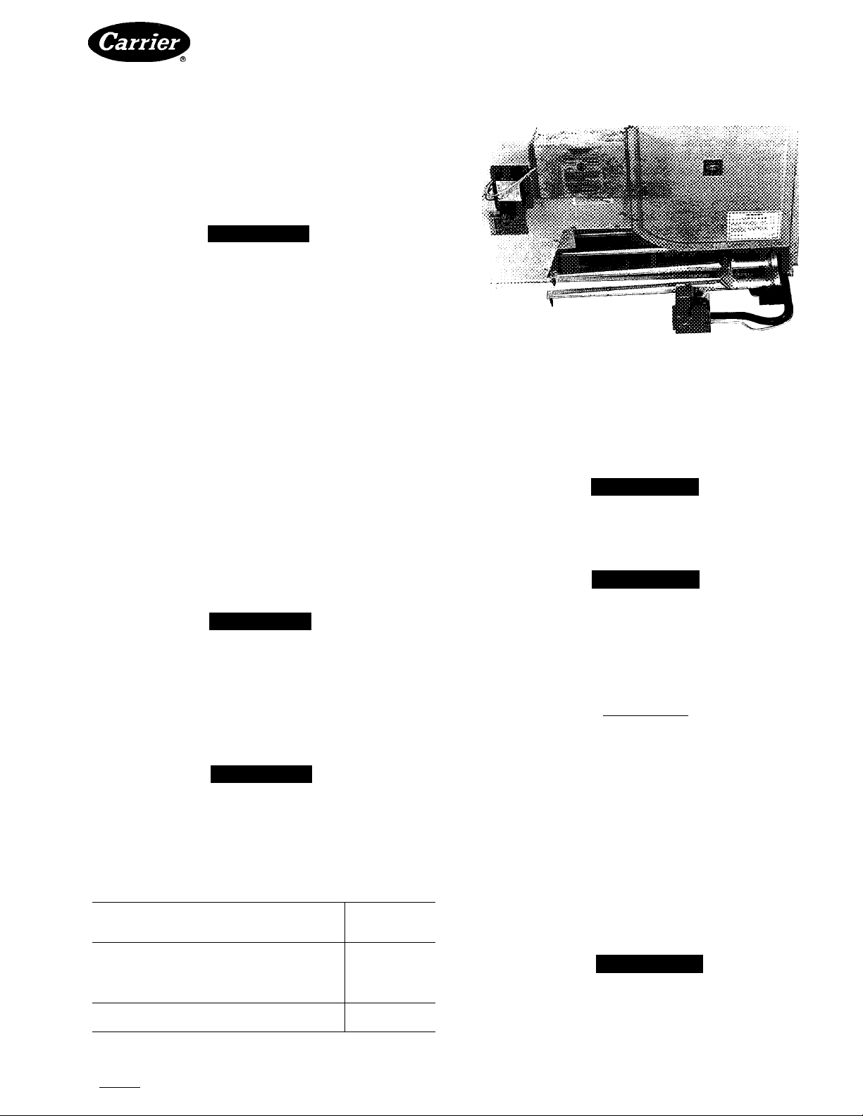
(with intermittent electronic ignition) is shown in Fig. I.
This furnace has been designed to interface with splitsystem cooling equipment (approved by UL) to provide
year-round air conditioning. The blower is sized for
both heating and cooling. Table I provides physical
data and dimensions of the furnaces, and Table 2 pro
vides airflow data.
The furnace installation must conform with local
building codes or, in the absence of local codes, with the
National Fuel Gas Code, NFPA54-I984/ANSI Z223.I-
I984 For complete information on installation standards
consult the National Fuel Gas Code, obtainable at a
nominal cost from the National Fire Protection Associa
tion, Inc., Batterymarch Park, Quincy MA 02269 or the
Table 1 — Physical Data and Dimensions
SIZE 58ED/PB FURNACE
INPUT (1000 Btuh)*
HEATING CAPACITY (1000 Btuh)t
Non-Weatherized
Indoor
TEMPERATURE RISE (F)
DIMENSIONS (ft-ln.)
NUMBER OF BURNERS
SHIPPING WEIGHT (lb)
‘Ratings shown are for elevations up to 2000 ft above sea level.
For elevations above 2000 ft, deduct 4% of input capacity for
each 1000 ft above sea level
Manufacturer reserves the right to discontinue, or change at any time, specifications or designs without notice and without incurring obiigations.
Book|1 |4 PC101 Catalog No 535-834 Printed in U S A Form 58ED,PB-1SI Pg 1 6-85 Replaces: 58PB-1 SI
Tab |6a|8a
Length A
Width B
Duct Opening C
Vent Diameter D
E
F
G
OSO
50
38
39
35-65
4-6
1- V/2
0-11 Ye 0-11 Ye 1-ЗУв
0-4
1- 8%
0- 8%
1-4
1- 9У4 1- 9'/4
1- 7%
2
155
For replacement items use Carrier Specified Parts.
075 100
75 100 125 140
56
58 77
40-70 40-70
4-6
1- VÁ
0-4 0-5
1- 8У4 1-8У4
0- 8% 0-6У8
1-4
1- 7У4 1-7У4 1- 5У4
3
165 190
fDetermined as per U S Government standard tests
75
4-6
1-5
1-4
1-9У4
4
125
94 105
96
40-70
4-8
1- 8Уг 2-0
1- 6Ув 1-10Ув
0-5 0-6
1- 8У4
0- 9У2 0- 9Уг
1- 5У4
1-11 '/4
5
230 250
140
108
40-70
4-8
1- 7У4
1- 5У4
1-11 '/4
1- 5'/4
6
Page 2
58ED,PB
HEATING A COOLING
American Gas Association, 1515 Wilson Boulevard,
Arlington, VA 22209.
A WARNING
The furnace cabinet must have an uninterrupted or
unbroken electrical ground to minimize personal
injury if an electrical fault should occur. The unit
must also be electrically grounded in accordance
with local codes, with the National Electrical Codes
ANSl/NFPA No. 70-1984 or the latest edition. Do
not use gas piping as an electrical ground.
INSTALLATION
Step 1 — Select Location — This furnace may be
located in an attic, basement crawl space, alcove or
suspended from the ceiling of a utility room or basement.
As shown in Table 3, the minimum clearances, or greater,
must be provided between the furnace and adjacent
construction.
A WARNING
Failure to comply with all the recommended clear
ances will result in a fire hazard.
If a furnace is to be installed in a residential garage, it
must be installed so the burners and the ignition source
are located not less than 18 in. above the floor and the
furnace must be located or protected to avoid physical
damage by vehicles.
The furnace should be located as close to the chimney
as possible in order to keep vent connections as short and
direct as possible. The furnace should also be located as
near to the center of the air distribution as possible, and
should be mounted level.
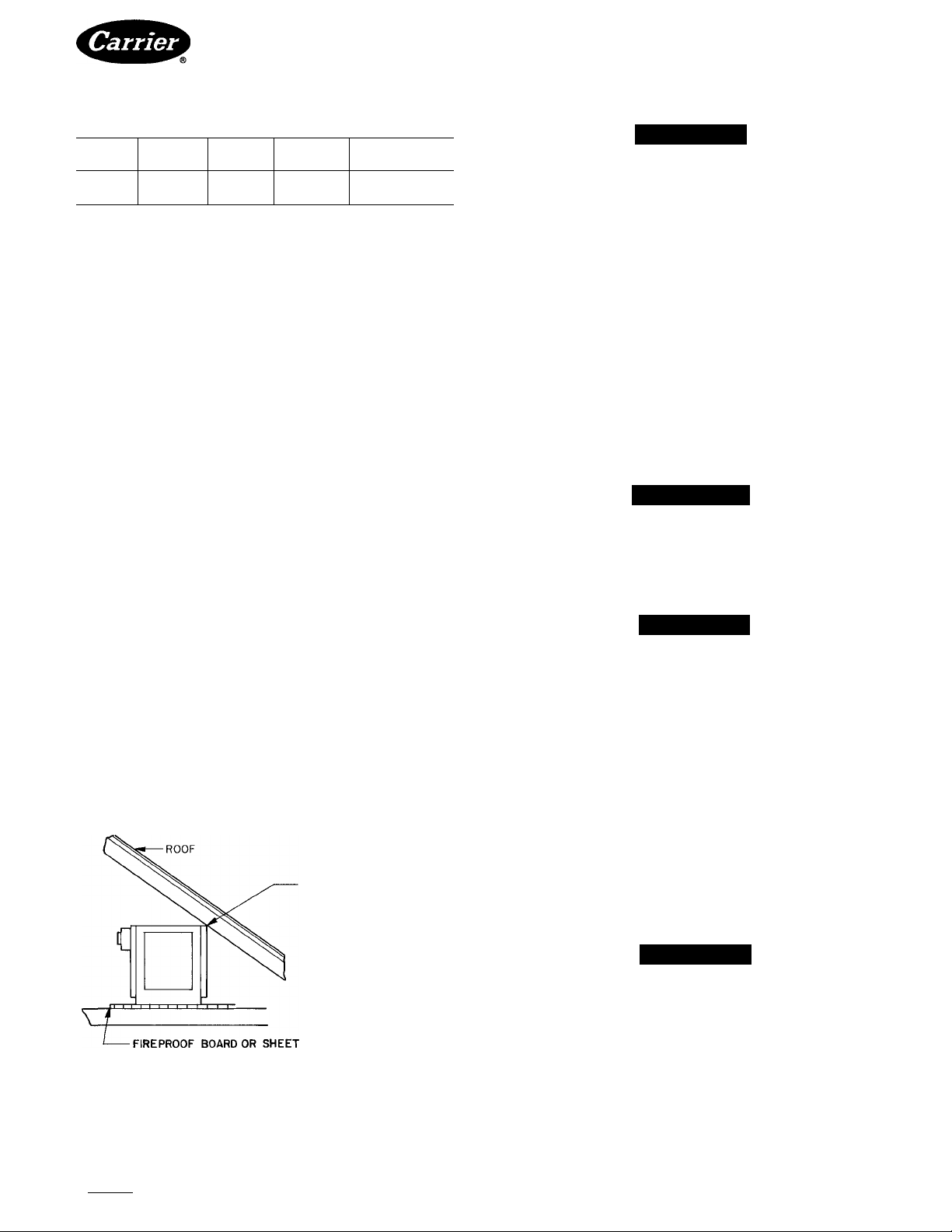
Horizontal Gas-Fired Furnaces
Since this furnace is suitable for attic installation, it
must not be installed directly on carpeting, tile or other
combustible material. Line contact is only permissible
between lines formed by the intersection of the furnace
top and two sides and the building joists, studs or
framing. See Fig. 2
A clearance of at least 30 in. should be provided at the
front of the furnace for combustion air and servicing.
For attic installations, the passageway and service area
adjacent to the furnace should have a floor installed.
The areas adjacent to the combustion air openings must
be covered with fireproof board or sheet metal extending
a minimum of 12 in. from the furnace. See Fig. 2.
If the furnace is to be installed in a crawl space, consult
local codes. Use of a concrete pad one to 2 in. thick is
recommended.
If the furnace is to be suspended from the ceiling, it is
necessary to use steel pipe straps around each end of the
furnace. These straps should be attached to the furnace
with sheet metal screws and bolted to the rafters. The
furnace may also be suspended by an angle iron frame
bolted to the rafters.
A WARNING
Do not place combustible material on or against
the draft hood.
A WARNING
The furnace is not watertight and is not designated
for outdoor installation.
Table 2 — Blower Data (Direct Drive)
FURNACE 58ED/PB
SERiES (15th Digit
of Model No.)
BLOWER SIZE (in)
DXW
MOTOR HP (PSC)
SPEED TAP
WIRE COLOR
BLOWER RPM
EXTERNAL STATIC
PRESSURE (in wg)
A
10x4 10x4
%
Hi
Lo
Red BIk
830 1070
20 50
930
765
050
B c
10x6 10x6
Va
Lo Hi
Red BIk
1080 700 920 1020
760
50 20
20
1220 790 1165
735
075 100
A B c A B c C
10x6 10x6
'/3 %
Lo Lo
Red Red BIk Blu BIk Blu Red
Va
Hi Med Hi
790
20 50 20 50 20 20
1130 995 1260 1090
'/3
Med Lo
1060 820 860
10x8
10x8 10x8
Va
'4
Hi
Med Hi Med
BIk Blu
990 730 1050
50 20 50
AIRFLOW (Cfm)
1290 1090 1530 1360 2010 I860
1310
'/3
BIk Blu
840 1070
20 50 20 50
Hi
BIk
125 140
D B c
12 X 9
'h
Med Hi
Blu BIk
12x9 12 X 12 12x12
3/4
Med Hi
820
Blu BIk Blu BIk Blu
920
1000
20 50 20 50 20
1810
2115
’/2
Med
1070 970
2100 1930
3/4
Hi Med
980 780
2350 2100
A WARNING
When operating furnace in heating mode, the static pressure
and the temperature rise (outlet air temperature minus room
temperature) must be within those limits specified on the
AGA rating plate.
Book|1 |4 PC101 Catalog No 535-834 Printed in U S A Form 58ED.PB-1 SI Pg 2 6-85 Replaces: 58PB-1 SI
Tab I6al8a
Manufacturer reserves the right to discontinue, or change at any time, specifications or designs without notice and without Incurring obligations.
For replacement Items use Carrier Specified Parts
Page 3
58ED,PB
HEATING A COOLING
Table 3 — Alcove Clearances (In.)
TOP
8 6
’With draft hood in front of furnace
tWith draft hood on back of furnace
SIDES
BACK
8*
18t
DRAFT
HOOD
Line
Contact
SINGLE
WALL VENT
6
Step 2 — Provide Air For Combustion and
Ventilation — For an unconfined space (more than
50 cu ft of volume per 1,000 Btu of aggregate input rating
of all appliances installed in that space) such as a base
ment or attic, infiltration air is normally adequate to
provide air for combustion, ventilation and dilution of
flue gases. Adjoining rooms may be included if there are
no doors between the rooms
For a confined space, where air is taken from an
interior space, 2 permanent openings of equal area are
required. One opening must be within 12 in. of the ceiling
and the other must be within 12 in. of the floor. Each
opening must have a free area of at least 1 sq in. per
1000 Btu of total input rating but not less than 100 sq
inches.
If the outside air is supplied to a confined space, then
the 2 openings must be equal and located as above and
the free area of each must be:
Horizontal Gas-Fired Furnaces
A CAUTION
Whenever this furnace is installed in an area along
with one or more gas appliances, the total Btu input
of all appliances must be included when determining
the free area requirements for combustion and
ventilation air openings.
When ducts are used, they must be of the same cross-
sectional area as the free area of the openings to which
they connect. The minimum dimension of rectangular
air ducts must not be less than 3 inches.
The free area through a design of louver or grille
should be used in calculating the size opening required
to provide the free area specified. If the design and free
area is not known, it may be assumed that wood louvers
have 20-25% free area and metal louvers and grilles have
60-75% free area. Screens used must not be smaller than
1/4 in. mesh and louvers shall be fixed in the open posi
tion or interlocked with the equipment so that they are
opened automatically during equipment operation.
A WARNING
Do not block the combustion air openings in the
furnace. Any blockage will result in improper com
bustion and may result in a fire hazard or unsafe
condition
1. Onesqin. per 4,000 Btu of total input rating when
the air is directly communicated from the outdoors.
2. One sq in. per 4,000 Btu of total input rating when
the air is brought in through vertical ducts.
3 One sq in. per 2,000 Btu of total input rating when the
air is transferred through horizontal ducts.
LINE CONTACT ONLY
PERMISSIBLE BETWEEN
TOP CORNERS OF FURNACE
AND BUILDING JOISTS.
STUDS OR FRAMING.
KEEP ALL INSULATING
MATERIAL CLEAR OF
FURNACE. INSULATING
MATERIALS MAY BE
COMBUSTIBLE.
METAL EXTENDING 12 IN, FROM
UNDER COMBUSTION CHAMBER
Fig. 2 — Attic Installation Showing Point Contact
A CAUTION
For an attic installation, keep insulation 12 in. or
more away from any furnace openings. Some types
of insulating materials may be combustible.
Step 3 — Assemble Furnace — The burner and
controls are shipped in place and the furnace high- and
low-voltage wiring is complete to facilitate the installa
tion. Low-voltage wiring to the field-supplied thermostat
is necessary to complete the unit wiring (see Step 7 —
Make Electrical Connections).
In order to accommodate all the possible field installa
tions that may exist, the unit is designed so that the gas
valve, controls and draft hood assembly may be
assembled on either side of the furnace. Refer to Com
ponent Reversal section for details. After reversal (if
required), return to this section.
A CAUTION
Remove cardboard shipping insert from eye of the
blower scroll before energizing blower.
DRAFT HOOD — In order to save shipping space the
draft hood is shipped disassembled (on models 125 and
140 the left panel is spotwelded in place). Remove the
draft hood components from the blower compartment
(on some models the panels might be packed outside the
furnace jacket). On the models 50, 75 and 100 there will
Book|1 |4 PC101 Catalog No 535-834 PrintedinUSA Form 58ED.PB-1 SI Pg 3 6-85 Replaces: 58PB-1SI
Tab l6a|8a
Manufacturer reserves the right to discontinue, or change at any time, specifications or designs without notice and without incurring obiigations.
For replacement items use Carrier Specified Parts
Page 4
r
58ED,PB
HEATING & COOLING
be a wrapper, 2 panels (one marked with an “R”, the
other marked with an “L”) and a hardware package.
Refer to Fig 3 to assemble the draft hood. Depending
on the model, one or both panels are slid into the proper
location in order to line up the 4 mounting holes. Secure
the panel(s) with the screws provided
After completing the draft hood assembly, it is
advisable to check the overall size with Table 4.
Install the draft hood over the selected flue opening by
placing it on top of the draft hood clip and securing it to
the furnace jacket with screws provided. Adhere to the
necessary clearances as shown in Table 3.
Table 4 — Draft Hood Dimensions (in.)
FURNACE
58ED/PB
050
075
100
125
140
LENGTH
16
16
16 10
17'/4
17'/4
HEIGHT
10
10
10
10
DEPTH
8
8
8
8
8
PIPE DIA.
4
4
5
5
6
Step 4 — Size Ductwork— Proper ductwork sizing
is necessary to ensure satisfactory heating operation
Ductwork should be in accordance with the latest editions
of NFPA-90A (Air Conditioning Systems) and NFPA-
90 B(Warm Air Heating and Air Conditioning Systems).
Follow these recommendations when installingductwork:
1. Install locking-type dampers in all branch or indi
vidual ducts to balance out system. Dampers should
be adjusted to impose the proper static pressure at
the outlet of the furnace.
2 Noncombustible flexible duct connectors are recom
mended to connect both the supply and return ducts
to the furnace
3 In cases where the return air grille is located close to
the fan inlet, there should be at least one 90 degree air
turn between fan and inlet grille. Further reduction
in sound can be accomplished by installing acoustical
air turning vanes and/ or lining the inside of duct with
acoustical material.
Horizontal Gas-Fired Furnaces
When installing the furnace with cooling equipment
for year-round operation, the following recommenda
tions should be followed for series or parallel airflow:
1. In series airflow applications, the coil is mounted
after the furnace in an enclosure in the supply air-
stream. The furnace blower is used for both heating
and cooling airflow.
A WARNING
The coil must be installed on the air discharge
side of the furnace. U nder no circumstance should
the airflow be such that cooled, conditioned air
can pass over the furnace heat exchanger. This
causes condensation in the heat exchanger and
possibly early failure due to rust.
2. In parallel flow installation, dampers must be pro
vided to direct air over the furnace heat exchanger
when heat is desired and over the cooling coil when
cooling is desired.
IMPORTANT: The dampers should be adequate
to prevent cooled air from entering the furnace,
and if manually operated, must be equipped with
means to prevent operation of either the cooling
unit or furnace unless the damper is in the
full cool or heat position.
Step 5 — Vent Furnace — This furnace must be
A CAUTION
Air openings in burner cover, return air grilles, and
warm air registers must not be obstructed.
A WARNING
When supply ducts carry air circulated by the furnace
to areas outside the spaces containing the furnace,
return air shall also be handled by a duct sealed to
the furnace casing and terminating outside the space
containing the furnace.
Manufacturer reserves the right to discontinue, or change at any time, specifications or designs without notice and without incurring obligations.
Book|1 14 PCiOl Catalog No 535-834 Printed in U S A Form 58ED,PB-1SI Pg4 6-85 Replaces: 58PB-1SI
Tab l6al8a
For replacement items use Carrier Specified Parts.
vented to the outside and in accordance with local codes
or requirements of the local utility. In the absence of local
codes, venting should conform to the requirements of
the National Fuel Gas Code (NFPA 54-1984/ANSI
Z223.1-1984 Part 7).
For additional venting information, refer to ANSI/
NFPA 211 Chimneys, Fireplaces, Vents and Solid Fuel
Burning Appliances.
This furnace must not be vented into a solid fuel
burning chimney. The chimney must be checked for
deterioration. Correct the condition before venting
the furnace into the chimney. The chimney must be
properly lined and sized per National Fuel Gas Code
(ANSI Z223.1-1984/NFPA-54, 1984).
Page 5
58ED,PB
HEATING A COOLING
MASONRY CHIMNEY — This furnace can be vented
into an existing masonry chimney. Normal connections
to a chimney are made using single wall pipe; however,
single wall pipe is not approved to pass through any attic,
inside wall or concealed space or through any floor. For
further information, consult venting section of National
Fuel Gas Code.
TYPE B-1 VENT — The furnace is also approved for
use with a Type B-1 vent that terminates through the roof
(horizontal venting through an outside wall is not
approved). The vent must be terminated with a listed
cap or roof assembly. This venting must be installed in
accordance with the vent manufacturer’s instructions
and be in accordance with all local codes.
ATTIC INSTALLATION — Attic and/or National Fuel
Gas installations require the use of Type B or Type L vent
material The following requirements are provided for
venting system;
1. Ensure the chimney flue is clear of any dirt or debris.
2. Ensure the chimney is not serving an open fireplace.
3. Never reduce the pipe size below the outlet size of
the furnace.
GAS
SUPPLY
Horizontal Gas-Fired Furnaces
4. All pipe should be supported using the proper clamps
and/ or straps
5. All horizontal runs of pipe must have an upward
slope of 1/4 in. per foot.
6. All runs of pipe should be as short as possible with
as few turns as possible.
7. Seams must be tightly joined and checked for leaks.
8 The flue pipe must not extend into the chimney,
but be flush with the inside chimney wall.
9. The chimney or gas vent must extend 3 ft above the
highest point where it passes through a roof of a
building and at least 2 ft higher than any portion of a
building within a horizontal distance of 10 feet. It
shall also extend at least 5 ft above the highest
connected equipment flue collar.
10 Check local codes for any variance.
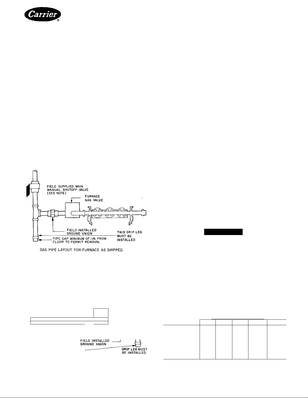
Step 6 — Connect Gas Piping — Install gas piping
to provide a supply of gas sufficient to meet the maximum
demand without undue loss of pressure between the gas
meter and the furnace. The gas line to the furnace should
be a separate line direct from the meter, unless the
existing gas line is of ample capacity. Refer to Table 5
for sizing gas piping.
Use a joint compound (pipe dope) resistant to the
action of liquefied petroleum gases or to any other
chemical constituents of the gases to be conducted
through the piping.
Before any system of gas piping is finally put into
service, it should be carefully tested to determine if it is
gas tight. The piping must withstand a pressure of 6 in. Hg
for a period of 10 minutes or as required by local
authority.
note:
LOCATE MANUAL SHUTOFF VALVE AS REQUIRED
BY THE LOCAL AUTHORITY OR CODE IN THE
ABSENCE OF SUCH A CODE, LOCATE THE
MANUAL MAIN
FROM THE FLOOR
FIELD SUPPLIED MAIN
MANUAL SHUTOFF VALVE
FURNACE
GAS VALVE -
Tl
CD
r'l
PIPE CAP MINIMUM OF I IN. FROM
FLOOR TO PERMIT REMOVAL
GAS PIPE LAYOUT AFTER REVERSING COMPONENTS
(SEE NOTE)
r
Lj
Fig. 4 — Gas Pipe Layout
A WARNING
The furnace and its individual shutoff valve must be
disconnected from the gas supply system during any
pressure testing of that system at test pressures in
excess of 1 / 2 psig. The furnace must be isolated from
the gas supply piping system at pressures equal to or
less than 1/2 psig.
GAS
SUPPLY
The recommended method for installing the gas piping
to the furnace is shown in Fig. 4. Also shown is correct
piping if the gas valve and controls have been reversed
in the field.
Table 5 — Gas Pipe Sizing (Cu Ft of Gas per Hour)'*
)
PIPE (ft)
10
20
30
40
50
75
100
150
* Based on gas pressures of 0 5 psig or less and pressure drop of
0 3 in wg and 0 60 specific gravity gas
DIAMETER OF PIPE — IPS (in.)
Vr % 1 IV4
132
278
92
190
73
152
63
130
—
115
—
—
_
520 1050
350 730
285 590
245 500
215 440
93 175 360
150 305
79
64 120 250
IV2
1600
1100
890
760
670
545
460
380
Manufacturer reserves the right to discontinue, or change at any time, specitications or designs without notice and without incurring obligations.
Book|1 |4 PC101 Catalog No 535-834 PrintedinUSA Form 58ED.PB-1SI Pg5 6-85 Replaces; 58PB-1 SI
Tab l6a|8a
For replacement items use Carrier Specified Parts
Page 6
58ED,PB
HEATING & COOLING
Support all gas piping independent of the furnace. For
propane gas, a tank regulator is required to reduce supply
pressure to 12-13in.wg. For manifold pressure, see
Table 6.
Check all piping for leaks using soapy water and a
brush.
A CAUTION
Never use an open flame when testing for gas leaks!
Use a soap and water solution
A 1/8 in. NPT plugged tap accessible for test gage
connection must be installed immediately upstream of
the gas supply connection to the furnace if one is not
supplied on gas valve.
BURNER ORIFICES — The furnace is supplied with
standard orifices for the gas shown on the rating plate.
Table 6 shows combinations of heating values and
specific gravities for various fuels, from which proper
input may be obtained
Regardless of the type of gas used, when installation is
at an elevation of 2000 ft or more above sea level, orifices
may need to be changed, depending on local gas value.
For operation at elevations above 2000 ft, input ratings
should be reduced at the rates of 4% for each 1000 ft
above sea level. To change orifices, remove the burner
removal cover on the gas valve side of unit. Remove
manifold locking device and slide the manifold tray back
until each burner is clear of heat exchanger tube. See
Fig. 5 Pull the manifold tray forward until burners are
clear of furnace. Remove the locking device from each
burner and pull each burner back off the orifice.
A CAUTION
Take care when removing the pilot burner not to
damage the pilot gas line.
Horizontal Gas-Fired Furnaces
Fig. 5 — Burners Removed From Furnace
After securing the manifold assembly, replace all other
components and/or wiring, being sure that all connec
tions and screws are tightened.
A WARNING
If it is necessary to adjust the manifold pressure
more than 0.3 in. wg, the orifices must be changed
A WARNING
Never set the furnace input rate above that shown
on rating plate.
Use the following formula to determine the furnace
input rate:
After removing orifices, ensure the new orifiees are
Input (Btuh) = Heating Value of Gas (Btu/cu ft)
seated properly and tightened. Replace burners correctly
and secure with the locking device before replacing and
securing the manifold assembly.
X 7200 sec/2 hr
Time in sec for 2 cu ft of gas
Example. If the heating value of natural gas is 1015
_______
______
Btu/cu ft and it takes 75 seconds to burn 2cuft of gas,
A CAUTION
The manifold must be properly positioned in order
to engage the locking mechanism
then:
Input (Btuh) = 1015 Btu/cu ft X 7200 sec/2 hr
75 sec/2 cu ft
Input = 97,440 Btuh
When checking rate, make sure all other gas appliances
are shut off except for pilot burners.
Table 6 — Burner Orifices
Step 7 — Make Electrical Connections — The
control system depends on the correct polarity of the
TYPE OF GAS
(Heating Value — SP GR)
BTU PER CU FT
NATURAL — MANIFOLD PRESS. 3.5 in. wg
800 — 0.6
900 — 0.6
1000 — 0.6
1100 — 0.6
PROPANE — MANIFOLD PRESS. 10 in. wg
2500 — 1.53
Book|1 |4 PC101 Catalog No 535-834 Printed in U S A Form 58ED.PB-1 SI Pg6 6-85 Replaces: 58PB-1SI
Tab l6al8a
Manufacturer reserves the right to discontinue, or change at any time, specifications or designs without notice and without incurring obligations.
ORIFICE SIZE
(Drill No.)
43
44
45
46
54
For replacement items use Carrier Specified Parts
power supply. Connect field power wiring and field
ground wire as shown in Fig. 6 and 7.
A WARNING
The unit cabinet must have a separate uninterrupted
or unbroken electrical ground to minimize personal
injury if an electrical fault should occur.
Page 7

“ü
o
(O
O 3
FIELD POWER SUPPLY C115-1-60)
CN0TE5 #2,3 g 4)
SCHEMATIC DIAGRAM
ORN
WHT
<i~I <ri^
ic
9 ij> o Cj)
PI
BLK
GRN
YEL
m
1
GV
(NOTES #2, 3 g 4)
GROUND
COMPONENT ARRANGEMENT
YEL
TB
MLS
g
FS
WHT
IFR
DS
TRAN
WHT
C--BLK-
GRN
RED-i
FM
BLK
BLU WHT
^ o>.1/ 3
Q. sS
« d' Ä
i c 3
E CO i®
= > 45
<D ^
3 O
« 2.
c S:
w o
O 0)
S "n 5’
q o 3
0 5*"
-» 3 o
W C71
•O 05 Q.
g m ®
2; O 2.
<5' <o
m 3
T3 r «
0) _L <
2. 05 S.
"D
CD
THERMOSTAT g SUB-BASE
(NOTE #1)
— Capacitor
Cap.
CC
— Cooling Compensator
DS — Door Switch
IC — Ignition Control
FM
— Fan Motor
FS — Fan Switch
GV
— Automatic Gas Valve
HA — Heat Anticipator
— Indoor Fan Relay
IFR
— Limit Switch
LS
— Mam Limit Switch
MLS
— Outdoor Relay
OR
P — Pilot
— Pilot Igniter
PI
— Spark Igniter
SI
— Terminal Board
TB
NOTES;
1 USE THERMOSTAT PART NO. HH01PD042 WITH SUB-BASE
2. USE COPPER CONDUCTORS ONLY.
3. TO BE WIRED IN ACCORDANCE WITH NATIONAL ELECTRIC
4 MAKE FIELD POWER SUPPLY CONECTIONS TO BLACK AND
5. IF ANY OF THE ORIGINAL WIRE AS SUPPLIED WITH THE
6. IMPORTANT - UNIT HAS 5866 CONTROL, IF PILOT
7 DO NOT ATTEMPT TO LIGHT THE FURNACE MANUALLY
8. OR - OUTDOOR RELAY SUPPLIED WITH CONDENSING UNIT.
Fig. 6 — 58ED Furnace Wiring Label — Heat/Cool
LEGEND (FIG. 6 and 7)
Tran — Transformer
CommoH Potential (Not Actual Wiring)
_______Fieid Power Wiring
—Field Ground Wiring
______
Field Control Wiring
PART NO. HH93RZ03G OR ENG. EQUIVALENT.
(N.E.C ) AND LOCAL CODES. UNIT MUST BE GROUNDED
WHITE WIRES CAPRED WITH ORANGE WIRE NUTS.
FURNACE MUST BE REPLACED, IT MUST BE REPLACED
WITH WIRING MATERIAL HAVING A TEMPERATURE RATING
OF AT LEAST 105°C AND BE A MINIMUM OF 16 GA.AWG.
FLAME 15 NOT ESTABLI5HED, CONTROL WILL SHUT DOWN
THE SYSTEM. TO INITIATE A RE-IGNITION TRIAL,TURN
DOWN THERMOSTAT TO LOWEST SETTING, WAIT AT LEAST
60 SECONDS g THEN RESET THERMOSTAT TO ABOVE TEMP
o Component Connection (Unmarked)
O Component Connection (Marked)
Field Splice
—O— Junction
—•— Junction Thermostat to Subbase
T
o
Ñ'
o
3
O
fi)
0)
(D
Q.
T| cn
C 00
D o
c/) W
Page 8

58ED,PB
HEATING & COOLING
Horizontal Gas-Fired Furnaces
CC LU
I— O
o z
UJ 3
¿iJ
< C D O O <
ox cr 3 < Q 3
cn C 3 O 2
_( o
c r
<D
C L U
H- cn cn a: i:u
:3c 3
LU •
o cn
2 L U
< o
Q O
cr. o
o
O -j
a. cn OD
CD I—
3
o
2
z c
o cr
o o
cr :3c
2
3
Ln Q
LU
cr Cl
3 1 — < 2 X C
Q L U 3 ^
' n. ■< <C C 3 I
cn O L—
. 2 >— <
‘ 3 o
O ^ <C I— >
< L i_ t j_ — 1 z < O
O o I
O o I
Ln < o LH <D
3 2 cn
' cr 3
• 223
3 q : Q
) h- 3 2
•3X0
>- h- o
I 3 3
I X o o
h- Q 3
c
o
CO
0)
X
0)
n
(0
u
O)
c
o
(0
c
w
3
Li.
Q
LU
00
in
O
CO
Q>
C
o
d)
CTr
CL^r
3
Cno5
crcn
lU K
:3:(M
O it
Cl
3
Book 11 |4 PC101 Catalog No 535-834 Printed in U S A Form 58ED,PB-1 SI Pg 8 6-85 Replaces'. 58PB-1 SI
Tab I6al8a For replacement items use Carrier Specified Parts
Manufacturer reserves the right to discontinue, or change at any time, specifications or designs without notice and without incurring obligations.
Page 9

58ED,PB
HEATING & COOLING
Horizontal Gas-Fired Furnaces
o
o
0
(0
a>
1
c
0)
SI
(0
-I
O)
c
u
CD
a
oo
lO
d>
a>
n>
c
Book 11 14 PC101 Catalog No 535-834 PrintedinUSA Form 58ED,PB-1 SI Pg9 6-85
Manufacturer reserves the right to discontinue, or change at any time, specifications or designs without notice and without incurring obiigations.
Tab !6al8a For replacement items use Carrier Specified Parts
Replaces: 58PB-1SI
Page 10

58ED,PB
HEATING & COOLING
Horizontal Gas-Fired Furnaces
>
C
O
(0
0)
X
0)
n
(0
_l
u>
c
0)
o
(0
c
3
u.
m
0.
00
IT)
c
o
o
d)
Bookll 14 PC101 Catalog No 535-834 Printed in U S A Form 58ED,PB-1Sl Pg 10 6-85 Replaces; 58PB-1 SI
Tab l6a l8a For replacement Items use Carrier Specified Parts
Manufacturer reserves the right to discontinue, or change at any time, specifications or designs without notice and without Incurring obilgations.
Page 11

58ED,PB
HEATING & COOLING
Use only copper wire for 115v supply service to
furnace. When replacing any original wiring, use only
105 C, 16 gage AWG copper wire.
Instructions for wiring the thermostat are packaged
with the thermostat (field supplied). Make connections
as shown in wiring labels at the 24 v terminal board
located on the electrical junction box. When installing
accessories to this furnace, follow manufacturer’s
instructions included with the accessory Except for
thermostat wiring, a minimum of typeT (63 F rise) must
be used.
Step 8 — Install Filters — Filters and racks are
available as accessories. See Fig. 8 for recommended
filter size rating and type.
IMPORTANT: All furnaces must be equipped with
a filter.
Step 9 — Reverse Components (if required).
A WARNING
Before proceeding with component reversal, make
sure that all power is turned off upstream of furnace
and all gas piping is shut off and disconnected from
furnace.
A CAUTION
Before proceeding with field reversing, ensure a
correct wiring diagram is available and/or be
prepared to mark all wiring as it is disconnected.
Horizontal Gas-Fired Furnaces
All references to left or right side of furnace refer to
the furnace looking at the heat exchanger (supply
air side).
The gas valve, pilot burner components and controls
may be reversed as follows:
1 Loosen burner removal cover screws and remove
both covers
2 Disconnect all wires to gas valve and unplug the
igniter cable from the ignition control (if so
equipped).
3. Remove the manifold locking device and slide the
burner and manifold assembly back towards the
furnace inlet until the burners are clear of the heat
exchanger tubes. See Fig. 5.
4. Slide manifold assembly towards the front of furnace .
until it clears the blower deck.
NOTE: Keep manifold assembly straight while
removing. If manifold is cocked, then the assembly
will bind in burner box.
5. Place manifold on a work area and disconnect the
pilot tubing and thermocouple, if equipped, from the
valve
6. Using 2 pipe wrenches (one on the gas valve and
one on the manifold extension pipe), remove the
gas valve
7. Remove the manifold extension pipe from the
manifold (it may be necessary to put a pipe wrench
on the manifold pipe while turning the extension).
8. Using 2 pipe wrenches (one on the manifold pipe
between the pipe cap and burner orifices and one on
the pipe cap), remove the pipe cap.
9. Clean the threads on manifold pipes, gas valve and
pipe cap of any old pipe dope.
NOTE: Use a joint compound (pipe dope) resistant
to the action of liquefied petroleum gases or to any
other chemical constituents of the gases to be
conducted through the piping.
10. Using a suitable joint compound and 2 pipe
wrenches, replace the manifold pipe extension where
the pipe cap was. The pipe extension should be
tightened and positioned so that it is pointing
towards the back of the burners.
11. Using 2 pipe wrenches (one on the manifold exten
sion and the other on the gas valve), tighten gas
INPUT
(iOOO BTUH)
50
75
100
125 20i
140 I5Î
A
(IN)
I4i
I6|
valve to the extension and position the valve so that
the manual knob is in the 12 o’clock position
12. Using 2 pipe wrenches (one on the pipe cap and the
other on the manifold pipe), tighten the pipe cap to
the other end of the manifold pipe
13. Remove the screws holding the pilot bracket to the
crossovers of the first 2 burners When removing
pilot assembly, be carelul not to damage the pilot
note;
FILTER RACK TO INLET
END OF FURNACE INSTALLED
INTO RETURN DUCTWORK.
Fig. 8 — Accessory Filter Rack Assembly
Manulacturer reserves the right to discontinue, or change at any time, specifications or designs without notice and without incurring obligations.
Book|1 |4 PC 101 Catalog No 535-834 PrintedinUSA Form 58ED,PB-1SI Pgll 6-85 Replaces: 58PB-1SI
Tab I6al8a
For replacement items use Carrier Specified Parts
gas tubing and ignition cable (or thermocouple, if so
equipped).
NOTE This step is not required foi 050 size, as
there are only 2 burners
Page 12

58ED,PB
HEATING & COOLING
1415With the pilot bracket removed from burners, rebend
the pilot tubing and thermocouple at the second bend
per Fig. 10. Make sure there are no kinks in tubing.
Connect the 1/4 in. diameter pilot gas tubing (and
the thermocouple, if equipped on standing pilot
models) to the gas valve. Be careful not to kink the
aluminum tubing.
16. Check the pilot position as shown in Fig. 9 and 10.
17. Standing pilot models only: Mount the pilot bracket
on the crossovers of the first 2 burners on the side of
manifold where valve is now mounted (Fig. 10).
Connect thermocouple and the 1/4 in. diameter
pilot gas tubing to gas valve This requires adjust
ments to pilot tubing and thermocouple. It is ex
tremely important not to kink either the thermo
couple or aluminum tubing.
Insert the manifold tray back into the furnace and
18.
slide the burners into the heat exchanger tubes. The
locking device will not engage unless the manifold
is in the correct position.
Lock the manifold in place (on electronic ignition
19.
models, be sure the ignition cable or sensing lead
is not pinched under the burners).
Remove the junction box cover and disconnect the
20
motor leads.
21. Remove junction box. See Fig. 11. On standing
pilot models, remove 2 hole plugs from back side
of furnace and then remove junction hox.
IMPORTANT; Pull junction box straight out
from furnace until fan and limit is clear of side
panel.
22. Mount the junction box on the opposite side of
furnace. Ensure door switch is kept towards the
blower door when mounting junction box
Horizontal Gas-Fired Furnaces
EDGE OF PILOT HOOD TO BE FLUSH TO
NOTE; The fan and limit dial will be upside down
when junction box is properly reversed. This does
not affect the operation of fan and limit.
Remove the strain relief holding the motor wires,
23
route motor leads under blower, feed wires into back
of junction box and snap the strain relief into place.
Reconnect motor leads and replace junction box
24.
cover.
Replace hole plugs in openings where fan and limit
25
and motor leads were
26. Remove the draft hood and draft hood support clip
PILOT
TUBE
PILOT ASSEMBLY AS SHIPPED
FROM FACTORY
PILOT ASSEMBLY AFTER FIELD REVERSAL
PILOT LOCATION
Fig. 10 — Pilot Assembly
Manufacturer reserves the right to discontinue, or change at any time, specifications or designs without notice and without incurring obiigations.
Book|1 [4 PC101 Catalog No 535-834 Printed in U S A Form 58ED.PB-1S1 Pg 12 6-85 Replaces: 58PB-1 SI
Tab i6al8a
For replacement Items use Carrier Specitied Parts
Page 13

58ED,PB
HEATING & COOLING
27. Remove the flue box cover and flue box cover gasket
and remount them where the draft hood was located.
See Fig. 12. Do not glue gasket to cover plate.
28. Replace the draft hood support clip and the draft
hood where the flue box cover plate was located.
NOTE; All controls, wiring, draft hood and the
AG A lighting instruction plates must be located
on the same side of the furnace as the automatic
main gas valve. Reattach all wires to gas valve and
check against wiring diagram.
29. Elect}onic ignition models only: Reattach all wires
to the gas valve and the ignition cable to the ignition
control.
Check all wiring against the wiring diagram. Fig.
6 and 7.
30. After the furnace components have been reversed,
return to Step 3, Assemble Furnace Draft Hood and
proceed with remainder of installation.
START-UP AND ADJUSTMENT
Standing Pilot Models
OPERATIONAL CHECKOUT — The automatic gas
valve controls the flow of gas to both the pilot and
main burners. The manual valve built into the automatic
valve body has 3 positions- OFF, PILOT, and ON.
SEQUENCE OF OPERATION — The furnace operates
automatically. It is controlled by a thermostat which is
set at the desired temperature. When indoor temperature
/ drops below this setting, the thermostat turns on the
system.
When the thermostat calls for heat, power from the
transformer energizes the main gas valve (the pilot must
be lit already) and gas flows through the valve to the
burners. The pilot flame lights the burners.
A heat sensing switch automatically energizes the
blower when heat buildup is sufficient. The air is moved
by the blower over the heating element, thus warming it,
and it goes through the ducts to room registers.
When the thermostat is satisfied, the circuit is broken,
de-energizing the main gas valve and stopping gas flow
to the main burners.
Horizontal Gas-Fired Furnaces
The blower continues to run until the heat in the heat
exchanger is removed and then the sensing switch shuts
off the blower.
All forced air furnaces are equipped with a high
temperature limit switch which prevents the furnace
from overheating. If the furnace overheats for any
reason, the high temperature limit opens, breaking the
circuit to the gas valve. The blower motor continues to
run. The main burners cycle on limit until the fault is
corrected.
A WARNING
If overheating occurs, or if the gas supply fails to
shut off, shut off the manual gas valve to the furnace
before shutting off the electrical supply.
Electronic Ignition Models
OPERATIONAL CHECKOUT — The automatic gas
valve controls the flow of gas to both the pilot and main
burners. The manual valve built into the automatic valve
body has 2 positions: OFF and ON.
SEQUENCE OF OPERATION — The furnace operates
automatically. It is controlled by a thermostat which is
set at the desired temperature. When indoor temperature
drops below this setting, the thermostat turns on the
system.
When the thermostat calls for heat, power from the
transformer simultaneously energizes the pilot gas valve
(inside the main gas valve) and the spark igniter. After
the pilot flame is established, the electrode ceases to
spark and the flame sensing probe acts to energize the
main gas valve, permitting gas flow to the burners.
A heat sensing switch automatically energizes the
blower when heat buildup is sufficient. The air is moved
by the blower over the heating element, thus warming it,
and it goes through the ducts to room registers.
When the thermostat is satisfied, the circuit is broken,
de-energizing the main gas valve and stopping gas flow
to the pilot and main burners. The blower continues to
run until the heat in the heat exchanger is removed and
then the sensing switch shuts off the blower.
JUNCTION
BOX
FLUE BOX
COVER
(GASKET IS
UNDERNEATH)
Fig. 11 — Junction Box
(Model 58ED Shown)
Manufacturer reserves the right to discontinue, or change at any time, specifications or designs without notice and without incurring obligations.
BookH 14 PC101 Catalog No 535-834 PrintedinUSA Form 58ED,PB-1SI Pg 13 6-85 Replaces: 58PB-1 SI
Fig. 12 — Flue Box Cover
Page 14

58ED,PB
HEATING & COOLING
All forced air furnaces are equipped with a high
temperature limit switch which prevents the furnace
from overheating. If the furnace overheats for any
reason, the high temperature limit opens, breaking the
circuit to the gas valve. The blower motor continues to
run. The main burners cycle on limit until the fault is
corrected.
A WARNING
If overheating occurs, or if the gas supply fails to
shut off, shut off the manual gas valve to the furnace
before shutting off the electrical supply.
The furnace is equipped with either Honeywell S86E or
S86G intermittent pilot control.
S86E control. If the pilot fails to light, the pilot valve
and spark gap remain energized until there is a successful
ignition.
S86G control: If the pilot fails to light, the control
will shut down the system. To initiate a reignition
trial, turn down the thermostat to lowest setting, wait
at least 60 seconds, and then reset thermostat to a setting
above room temperature.
Starting Procedure
STANDING PILOT MODELS
1. Set the manual gas shutoff valve at OFF position.
Wait 5 minutes.
2. Be sure all electrical power to furnace is off.
3 Check all wiring using proper wiring diagram on
inside of blower door.
4. Light the pilot by following instructions on lighting
plate. (Main burners should not light.)
a) Remove burner cover.
b) Turn manual gas shutoff valve to PILOT position.
c) Depress dial, light pilot with a match or taper.
Keep dial depressed until pilot remains lit after
dial is released (approximately 30-45 seconds).
If pilot does not remain lit, repeat operation,
allowing a longer period before releasing dial.
d) Replace burner cover.
5. Adjust pilot flame to envelop the thermocouple a
distance of 3/8 to 1/2 inch. The adjusting screw for
pilot flame is located on main gas control. With
standing pilot, rate is approximately 1000 Btuh.
See Pig. 13.
Fig. 13 — Pilot Thermocouple or Sensor Position
6. With the pilot lit, set thermostat above room
temperature.
7. Turn on power supply to furnace. This energizes
gas valve which should click open. The burners
should not light.
Horizontal Gas-Fired Furnaces
Open the manual gas valve on the automatic gas
valve. Burners should light and remain on.
Check for leaks in manual valve, gas control valve
and gas connections using soap and water solution.
A CAUTION
Never use an open flame when testing for leaks.
Use soap and water solution.
lO. Leave burners on for 15 minutes before making
combustion adjustment
ELECTRONIC IGNITION MODELS
1. Set the manual gas shutoff valve at OFF position.
Wait 5 minutes.
2. Be sure all electrical power to furnace is off
3 Check all wiring using proper wiring diagram on
inside of blower door.
4 Set thermostat above room temperature.
5. Turn on power supply to furnace. This energizes the
pilot valve and spark igniter. The burners should
not light.
6. Turn dial on gas valve to ON position. The pilot
should light. When the sensing probe detects the
presence of pilot flame, the control de-energizes
spark igniter and energizes main gas valve. Main
burners should light and remain on. (If system shuts
down on S86G control, a reignition trial is
necessary.)
7. Check for leaks in manual valve, gas control valve
and gas connections using a soap and water solution.
A CAUTION
Never use an open flame when testing for gas
leaks. Use a soap and water solution.
8 Leave burners on for 15 minutes before making a
combustion adjustment.
Combustion Adjustment
ALL FURNACES — A primary air shutter assembly is
provided on all furnaces. The shutters are factory set for
natural gas furnaces and a closed position for LP gas
furnaces. Readjustment may be required to obtain
optimum setting. Shutters are individual to each burner,
so adjustment of the burner flame must be done one
burner at a time. See Fig. 14.
Loosen the locking screw and close the air shutter.
This should cause the burner flame to glow bright yellow
Open the shutter until the flame turns blue. Lock the
locking screw. See Fig. 15 for proper flame. Repeat this
procedure until all burners are properly adjusted. A
visual check of the main burner and pilot flame should
be made at the beginning of each heating season.
Safety Pilot Check — For Standing Pilot Models
Only. After operating for 15 minutes, turn the valve to
the OFF position. The pilot switch should snap open
between 20 seconds and 3 minutes later. To re-ignite
pilot, follow the nameplate instructions.
Manufacturer reserves the right to discontinue, or change at any time, specifications or designs without notice and without incurring obligations.
Book|1 |4 PC101 Catalog No 535-834 Printed in U S A Form 58ED,PB-1SI Pg 14 6-85 Replaces: 58PB-1SI
Tab |6a|8a
For replacement items use Carrier Specified Parts
Page 15

58ED,PB
HEATING & COOLING
LOCATION OF SHUTTER
LOCKING SCREW
SHUTTER ADJUSTING TAB
NOTE; LOOSEN LOCKING SCREW BEFORE
ADJUSTING SHUTTER. RETIGHTEN SCREW
AFTER FINAL ADJUSTMENTS ARE MADE.
Fig. 14 — Air Shutter Adjustment
Manifold Pressure Adjustment — For natural
gas, best results are obtained with a manifold pressure of
3.0 in. to 3.5 in. wg. Remove pressure tap pipe plug from
the gas valve and connect to a water manometer. Measure
gas pressure with the furnace on.
Turn regulator adjusting screw in to increase pressure,
or out to decrease pressure.
For LP gases, a 10 in. wg pressure is required. Input
rate must be maintained at ± 2%.
Fan Adjustment Check — This furnace is equipped
with a 3-speed direct drive motor to deliver a temperature
rise within the range specified on the rating plate, between
the return and supply plenums at the external duct static
pressure noted on the AGA rating plate. Consult the
wiring diagram for speed changes on the direct drive
motor. Adjust fan speed so that temperature rise is within
rating plate specifications.
Fan and Limit Control Check — After the furnace
has been operating for at least 15 minutes, restrict the
return air supply by blocking the filters or closing the
return air registers and allow the furnace to shut down on
high limit. The fan must continue to run. Remove the
restriction and the burner should come on in a few
minutes.
The operational checkout is now complete. Be sure to
adjust the thermostat to the desired setting and inform
the owner how to operate the furnace system before
leaving the jobsite.
Stopping the Furnace— Follow these procedures to
shut down the furnace for the summer, if required.
1. Disconnect electrical power to all accessories.
2. To shut down main burner, turn gas cock dial clock
wise to OFF position
3. (Standing pilot models only): To shut down both
pilot and main burner, depress dial and turn clockwise
to OFF position
4. Turn off all electrical power to furnace.
5. Turn off water supply to humidifier, if so equipped.
Horizontal Gas-Fired Furnaces
Fig. 15 — Burner Flames
SERVICE AND MAINTENANCE
A CAUTION
The ability to properly perform maintenance on this
equipment requires certain mechanical skills and
tools. If you are at all uncertain, contact your Carrier
dealer for qualified maintenance and service.
A WARNING
Turn off all gas and electrical power to furnace
before performing any maintenance or service on
unit. Failure to take this precaution may result in
personal injury due to electrical shock or uncon
trolled gas leakage.
NOTE; Furnace is equipped with a blower door switch
which cuts electric power when blower door is removed.
Air Filter — In order to aequaint the user of the furnace
with proper procedure for inspecting and cleaning the
filter, the installer should instruct the user to locate,
remove, clean and replace the furnace filter(s).
NOTE: If furnace is equipped with accessory filter rack,
refer to section on page 11.
A CAUTION
Personal injury or property damage may result if
furnace is operated with the blower compartment
door removed. A lack of adequate combustion air
may cause the main burner flame to be drawn out of
the furnace unless blower compartment door is
secured.
After inspecting or replacing the filter, be sure that
the blower compartment door is securely fastened in
place. Never operate the furnace without a filter.
Lubricating Motors — Direct drive motor and
blower assemblies are factory lubricated and normally
do not require oiling.
Bookjl |4 PC101 Catalog No 535-834 Printed in U S A Form 58ED,PB-1SI Pg 15 6-85 Replaces: 58PB-1SI
Tab l6a|8a
Manufacturer reserves the right to discontinue, or change at any time, specifications or designs without notice and without incurring obligations.
For replacement items use Carrier Specified Parts
Page 16

58ED,PB
HEATING & COOLING
Cleaning Heat Exchanger and Venting System
— The heat exchanger and venting system should be
checked each year by a qualified dealer. If necessary,
the following procedures should be performed:
1. Make sure that all utilities are turned off upstream
of the furnace (both gas and electrical supplies),
2. Remove burner covers, manifold assembly with
burners, vent connectors and draft hood.
3. Clean flue box, flue ways, burner box and burners
with brush and/or vacuum cleaner.
4. After cleaning, check pilot for proper position.
Replace all parts.
Table 7 — Trouble Analysis Chart for Standing Pilot Models
Turn off gas and electrical supplies to furnace before servicing. (Unless specific
test requires gas and electrical supplies )
Horizontal Gas-Fired Furnaces
5. Turn on gas and electrical supplies. Test for leaks
using soap and water solution.
A CAUTION
Never use an open flame when testing for gas
leaks. Use a soap and water solution.
6. Check for proper operation of all controls.
A WARNING
SYMPTOM AND PROBABLE CAUSE
BURNERS WILL NOT IGNITE
1 Pilot light out
2 No 115-v power to furnace
3 No 24-v power to control circuit
4. Miswired or loose connections
5. No gas at main burners
6 Flame probe or connecting lead is shorted or open 6, Correct electrical shorting or open circuit
INADEQUATE HEATING
1 Furnace undersized for application
2 Gas input to furnace too low
3 Limit switch cycles main burners
ALDEHYDE ODORS (CO), SOOTING FLAME,
FLOATING FLAME
1 Incomplete combustion — poor flame characteristics
1 Relight pilot If pilot does not remain lit, replace
thermocouple
2. Connect to power supply. Check fuse, wiring or circuit
breaker.
3. Check transformer; replace.
4 Check all wiring and wirenut connections.
5 Check to see if main valve is operating Look for loose or
broken wiring connections If no deficiency is found, replace
valve assembly.
1 Replace with proper size furnace
2. Check gas pressure at manifold. Clock gas meter for input
If too low, increase manifold pressure, or replace with correct
orifices.
3 OFF setting of fan control set too high; reset.
Dirty air filters; clean and reinstall.
Blower speed too low; use faster speed tap
Registers closed, restricted ductwork, open or remove
restriction
Check heat anticipator setting on thermostat, readjust.
1 Air shutter on burners closed, adjust to soft, blue flame.
Check all screws aroundflueoutletsand burner compartment,
tighten
Lack of combustion air, see Installation section
Cracked heat exchanger; replace
Overfired furnace; reduce input or change orifices.
Check vent for restriction; clean as required
REMEDY
Bookp |4 PC101 Catalog No 535-834 PrintedinUSA Form 58ED.PB-1SI Pg16 6-85 Replaces: 58PB-1 SI
Tab I6al8a
Manufacturer reserves the right to discontinue, or change at any time, specifications or designs without notice and without incurring obligations.
For replacement items use Carrier Specified Parts.
Page 17

58ED,PB
HEATING & COOLING
Table 8 — Trouble Analysis Chart for Electronic ignition Modeis
Turn off gas and electrical supplies to furnace before servicing (Unless specific
test requires gas and electrical supplies.)
SYMPTOM AND PROBABLE CAUSE
PILOT WILL NOT LIGHT
1 No spark at electrode
2 Spark shorting out to main burner
3. No gas at pilot burner
BURNERS WILL NOT IGNITE
1 No 115-v power to furnace
2. No 24-v power to control circuit
3. Miswired or loose connections
4 No gas at main burners
5 Flame probe or connecting lead is shorted or open
INADEQUATE HEATING
1. Furnace undersized for application
2 Gas input to furnace too low
3 Limit switch cycles main burners
Horizontal Gas-Fired Furnaces
A WARNING
REMEDY
1 Check spark gap, refer to Start-Up and Adjustment section
Check if Induced draft motor is operating If not, check power
to motor
Check for any blockage in flue venting system and chimney,
thereby preventing pressure switch from closing Unblock
if necessary
Check moisture or dirt accumulation on electrode ceramic,
clean ceramic with cloth
Cracked ceramic, replace pilot electrode assembly
Check for loose or broken wiring at and between electronic
control box and electrode. Replace wire as necessary
Check fuse or circuit breaker for 115-v supply to furnace
Check 24 v input to electronic control box If you read 24 v,
and above steps have been completed, replace electronic
control box assembly
Check pressure switch and tube assembly for any blockage
that prevents pressure switch from operating
Check continuity to determine if pressure switch has
disengaged
2 Realign electrode tip away from main burner but maintain
spark gap to pilot burner as noted above
3 Check to see if pilot valve is opening Look for loose or broken
wiring connections If no deficiency is found, replace valve
assembly
1 Connect to power supply Check fuse, wiring or circuit
breaker
2 Check transformer; replace
3 Check all wiring and wirenut connections
4 Check to see if main valve is operating. Look for loose or
broken wiring connections If no deficiency is found, replace
valve assembly
5. Correct electrical shorting or open circuit
1 Replace with proper size furnace
2 Check gas pressure at manifold Clock gas meter for input.
If too low, increase manifold pressure, or replace with correct
orifices
3 OFF setting of fan control set too high, reset
Dirty air filters, clean and reinstall.
Blower speed too low, use faster speed tap
Registers closed, restricted ductwork, open or remove
restriction.
Check heat anticipator setting on thermostat; readjust
ALDEHYDE ODORS (CO), SOOTING FLAME,
FLOATING FLAME
1 Incomplete combustion — poor flame characteristics
Manufacturer reserves the right to discontinue, or change at any time, specifications or designs without notice and without incurring obligations.
Book|1 [4 PC101 Catalog No 535-834 PrintedinUSA Form 58ED,PB-1SI Pg17 6-85 Replaces: 58PB-1 SI
1 Air shutter on burners closed, adjust to soft, blue flame
Check all screws around flue outlets and burner compart
ment; tighten
Lack of combustion air, see Installation section
Cracked heat exchanger, replace
Overfired furnace; reduce input or change orifices
Check vent for restriction; clean as required
>% Dorfo
Page 18

58ED,PB
HEATING A COOLING
Horizontal Gas-Fired Furnaces
t
t
BookM 14 PC101 Catalog No 535-834 Printed in U S A Form 58ED,PB-1Si Pg 18 6-85 Repiaces: 58PB-1Si
Tab IGaTSa For replacement items use Carrier Specified Parts
Manufacturer reserves the right to discontinue, or change at any time, specifications or designs without notice and without incurring obligations.
 Loading...