

Page 1
installation, operation,
and maintenance instructions
542E
Sizes 024 thru 060
PACKAGED HEAT PUMPS
NOTE TO INSTALLER: Leave these instructions with the
unit after installation.
NOTE: The installation of this unit must conform to the
guidelines presented in these unit Installation Instructions.
Read and become familiar with this publication before start
ing installation.
INTRODUCTION
Models 542D and 542E Packaged Heat Pumps are fully selfcontained combinatipn heating/cooling units designed for
outdoor installation. Model 542E may be installed either on
a rooftop or ground-level slab. See Figure 1. Model 542D is
used with an accessory roof-mounting curb (P/N 304851-
302) and incorporates a down-discharge/return-air plenum
as an integral part of the unit. See Figure 2.
These units are factory-charged with R-22 refrigerant.
Installation is simple: connect condensate drain, air ducts,
high- and low-voltage.wiring, and install a field-supplied air
filter (except for model 542D which has factory-supplied air
filters).
All units can be connected into existing duct systems that
are properly sized and designed to handle an airflow of 350 to
450 ffimin per each 12,000 Btuh of rated unit capacity. See
Table I for indoor airflow requirements.
Accessory UL-listed, field-installed, supplemental electric
heat packages are available in a variety of KW and voltage
options. These electric resistance heaters mount inside the
unit blower compartment.
A full line of rooftop system accessories is available for field
installation. These accessories include plenums with facto
ry-supplied air filters (plenum not required with Model
542D), roof-mounting curbs, horizontal and downflow
economizers, barometric relief dampers, concentric diffuser
boxes, and flexible duct packages. Filter racks with air
filters are available for rooftop or ground-level installation.
NOTE: When installing any accessory item, see the Installa
tion Instructions packaged with the accessory.
IMPORTANT-READ BEFORE INSTALLING
1. This installation must conform with all applicable local
and national codes.
2. The power supply (volts, hertz, and phase) must corres
pond to that specified on unit rating plate.
3. The electrical supply provided by your utility must be
sufficient to handle the load imposed by this unit.
4. Refer to the 542D or 542E dimensional drawing for loca
tions of electrical inlets, condensate drain, duct connec
tions, and required clearances before setting unit in
place.
5. Styrofoam shipping blocks located between compressor
and divider panel and between accumulator and divider
panel must be removed. A failure to remove these blocks
can result in undesirable vibration noises being
transmitted into the conditioned space.
& 542D060
Cancels: 40542DP6-A
À
Figure 1—Model 542E
Figure 2—Model 542D060 Mounted on
Accessory Roof-Mounting Curb
GENERAL
Models 542D and 542E Packaged Heat Pumps have been
designed and tested in accordance with ARI Standards 24077 and 270-75, and these units are UL-listed.
This publication contains the following sections:
I. Moving and Setting Unit in Place
II. Condensate and Defrost Disposal
HI. Duct Connections
IV. Electrical Connections
V. Preparing Unit for Startup
VI. Startup and Adjustments
VII. Sequence of Operation
VIII. Care and Maintenance
40542DP16-A
6/1/80
A79110
A79111
BDP Company, Division of Carrier Corp.
Page 2
542E REQUIRED CLEARANCE (Inches)
Top of unit
Duct side of unit
Compressor access door access end...........................12
side
..................................
.........................
.........................................
CONTROL ACCESS DOOR
COMPRESSOR
ACCESS DOOR
48 Blower access door end
12 End opposite blower
30 Bottom of unit above
anticipated snow level.... 6
______
30
OUTDOOR FAN
ELECTRIC HEAT
HIGH-VOLTAGE INLET WITH
MULTIPLE KNOCKOUTS
A79071
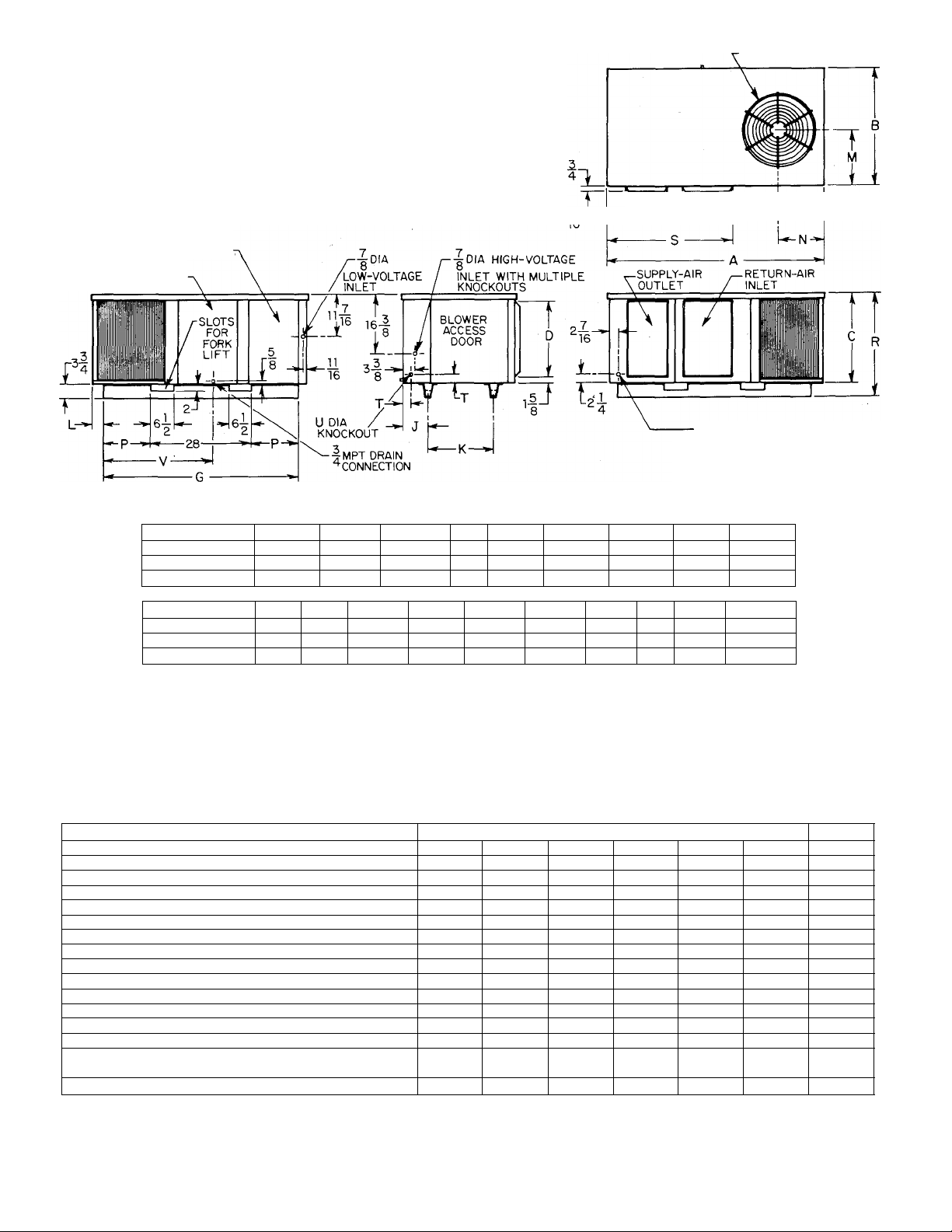
542E DIMENSIONS (Inches)
Size
A
B
024 & 030 60-3/16 32-3/16
036
60-3/16 32-3/16 24-13/16
c D E F
24-13/16
042, 048, & 060 68-3/16 40-3/16 30-13/16
L M N
Sizes
024 & 030 18-1/8
036
042, 048, & 060
K
18-1/8
25 1-1/2
1-1/2 15-3/32 12-9/16
15-3/32 12-9/16
1-1/2
20-3/32 15-1/8
21 11-1/2 13-5/16
21 13-3/4 13-5/16
21 16-3/8 17-5/16
P
14-1/2
R
28-9/16
14-1/2 28-9/16 37-1/8 2 7/8
18-1/2 34-9/16
G H J
57
57 4-5/8 6-15/16
65 5-1/8
T
S
37-1/8 2 7/8
44-1/4
2
Figure 3—542E Dimensional Drawing
TABLE l-RATiNGS, PERFORMANCE, & RECOMMENDED FILTER SIZES
MODEL
SIZE
SERIES
Rated Heating Capacity @ 47°F (Btuh)*
Total Power Consumption (Watts)*
COP*
Rated Heating Capacity® 17°F (Btuh)*
Total Power Consumption (Watts)*
COP*
**
024
A A A
030
26,000 30,000
2850 3450 3850
2.7 2.5
13,500 16,000 18,000
2350 2900
1.7 1.6
Rated Cooling Capacity @ 95°F (Btuh)* 25,500 30,000
Total Power Consumption (Watts)*
EER 7.6
Rated Indoor Airflow (Ft^/Min)*
3350 3900
7.7 7.5
850 1050
Rated External Statio Pressure (In. wc)* 0.10 0.15
ARI Sound Rating Humbert 19 19
Recommended Minimum Filter Size (Sq ln.)t
Standard-Type
Cleanable-or High-Capacity-Type 265
408 504
328
* Rated in accordance with ARI Standard 240-77.
t Rated in accordance with ARI Standard 270-75.
f Recommended field-supplied filter sizes shown are based on a velocity of 300 ft/min at the rated indoor airflow.
**Two 20 X 20 X 1 air filters are furnished with Model 542D060.
ttTo achieve the performance ratings indicated, the fresh-air and exhaust openings of the plenum section must be sealed airtight, the
fresh-air damper must be insulated, and the plenum section must be supported by a curb around an opening to the indoor airspace.
542E
036
35,000
042
A A
42,000
4600
2.7 2.7 2.8
21,000
3000
3700
1.8 1.7 1.8
35,000
4650
41,000
5150
8.0
1300
0.15
1535
0.15
19 18 18
624
406
737
479
6-7/8
6-15/16
7-1/2
TJ
V
27-7/8
27-7/8
7/8 35-3/16
048
48,000
060 060
A A
58,000
5100 6300
2.7
25,000 31,000
4150 5300
5420
58,00011
6300tt
2.7t-
31,00011
530011
1.7 1.711
47,000 57,000
6100 7600
57,00011
7600-t
7.7 7.5 7.511
1700 2000 200011
0.20
0.20 0.2011
20 20
816
530
960
624
**
**
-2-
Page 3
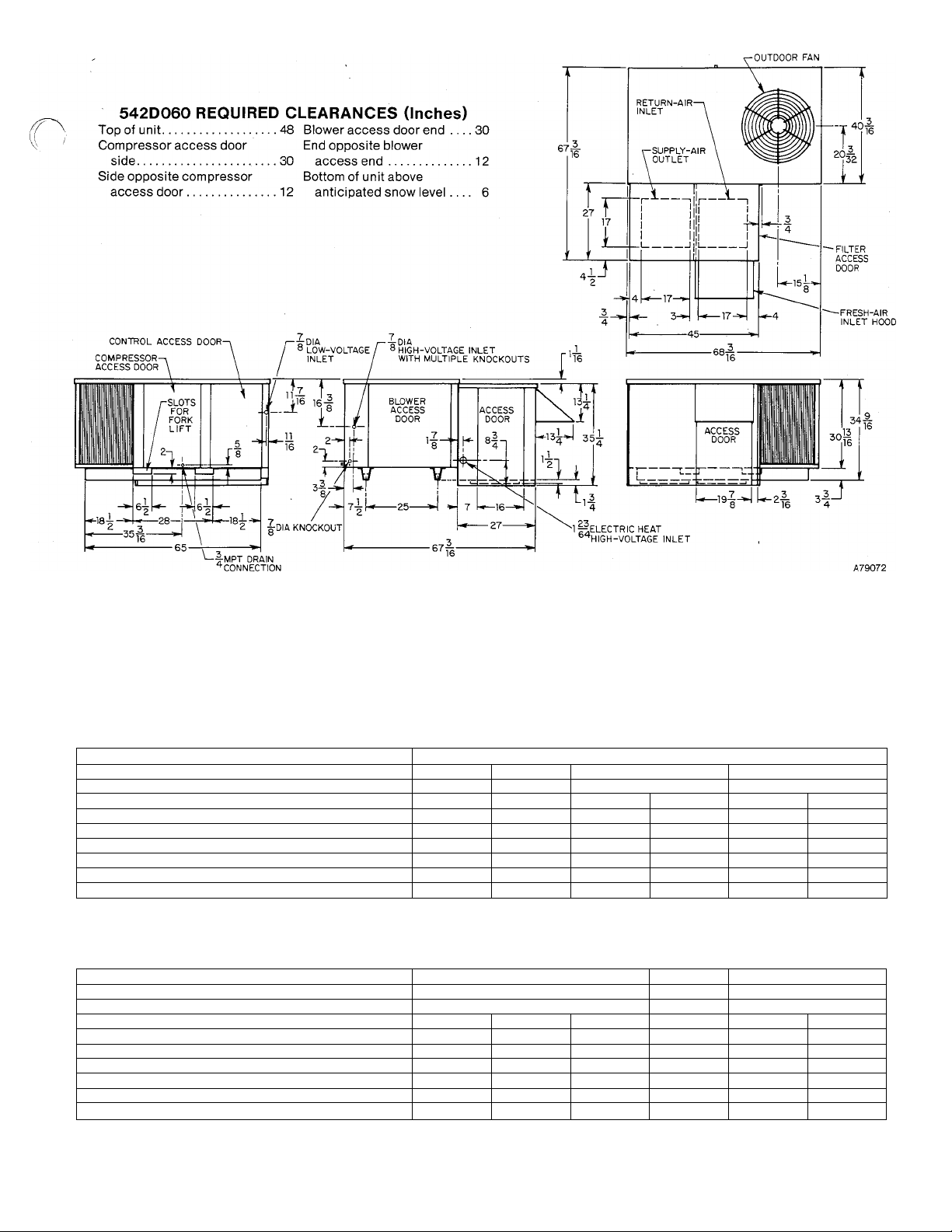
Figure 4—542D060 Dimensional Drawing
TABLE ll-ELECTRICAL DATA-MODEL 542E-SIZES 024 THRU 042
MODEL
SIZE
SERIES
Unit Volts—Phase (60Hz)
Operating Voltage Range
Total Unit Amps
Max Branch Circuit Fuse Size (Amps)
Unit Ampacity for Wire Sizing
Minimum Wire Size (AWG)*
Maximum Wire Length (Ft)*
J024 J030 J036 1 P036
A
A
208-230-1 208-230-1 208-230-1
197-253 197-253
197-253
16.7 22.7 23.9
30 45
20.2 27.5
10 10
115 85
542E
A
208/230-3 230-1
187-253 207-253 187-253
45 25
14.8
28.7 21.0
50 40
29.2 17.8 34.9
10
12 8 10
80 95 112
B042 1 P042
A
208/230-3
25.2
107
TABLE lll-ELECTRICAL DATA-MODELS 542E048, 542D060, & 542E060
MODEL
SIZE
SERIES
Unit Volts—Phase (60Hz)
Operating Voltage Range
Total Unit Amps
Max Branch Circuit Fuse Size (Amps)
Unit Ampacity for Wire Sizing
Minimum Wire Size (AWG)*
Maximum Wire Length (Ft)*
B048 P048
230-1
207-253 187-253
31.9
60
38.9 27.1 13.2 49.8 35.6
8
101 100 181 123
542E
A A A
E048 060 P060
208/230-3 460-3 230-1 208/230-3
414-506 207-253
22.4
10.9
45 20 60
10
14 6
* Use only copper wire for field connections to unit. Wire size is based on 60 or 75°C copper conductor at 86°F (30°C) ambient tempera
ture and ampacity shown in table. If other than 60 or 75°C copper conductor is used, if ambient temperature is above 86°F, or if voltage
drop of wire exceeds 2% of unit rated voltage, determine wire size from ampacity shown and the National Electrical Code. Wire lengths
shown are measured one way along the wire path between unit and service panel for minimum voltage drop.
542E 542D & 542E
187-253 414-506
40.9
30.1 13.7
50 25
8 12
119 229
E060
460-3
15.7
-3-
Page 4
USE SPREADER BARS TO PROTECT UNIT
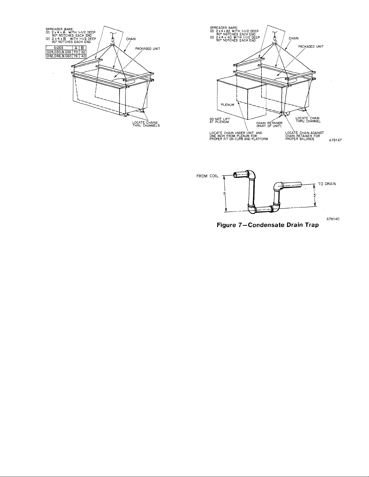
Figure 5—542E Suggested Rigging
USE SPREADER BARS TO PROTECT UNIT
A79148
I. MOVING AND SETTING UNIT IN PLACE
CAUTION: Use spreader bars when rigging the unit to be
lifted to protect the top and sides. Model 542E must be
rigged for lifting as shown in Figure 5. Model 542D must be
rigged for lifting as shown in Figure 6. Use extreme caution
to prevent damage when moving the unit. It must remain in
an upright position during all rigging and moving opera
tions. The unit must be level for proper condensate
drainage; therefore, the ground-level pad or accessory roof
mounting curb must be level before setting the unit in place.
When a field-fabricated support is used instead of the ac
cessory curb, ensure that the support is level and properly
supports the unit and plenum.
When selecting an installation site, locate the unit on the
side opposite the prevailing wind to assure proper operation
of the defrost cycle and to avoid snow drifts that could block
the outdoor coil. Be sure that the unit is installed at least 6
inches above the highest probable snow level to prevent block
age of the outdoor coil and to assure proper drainage of de
frosted ice.
A. Rooftop Installation
CAUTION: When installing the unit on a rooftop, be sure
that the roof will support the additional weight. Refer to the
Product Data Sheet (PDS) for Models 542D and 542E to
obtain total weight and corner weight information.
When installing a Model 542D Downflow Unit or a Model
542E End-discharge Unit with an accessory downflow
plenum, the accessory roof-mounting curb must be installed
on, and flashed into, the roof before unit installation. The
instructions for installing the curb are packaged with the
curb.
When installing a Model 542E without downflow plenum,
place the unit on a level base that provides proper support.
On flat roofs, be sure that the unit is located at least 4 inches
above the highest expected water level on the roof to prevent
flooding. Consult local codes for additional installation
requirements.
B. Ground-Level Installation
Place the unit on a solid, level concrete pad that is a
minimum of 4 inches thick and that extends approximately
2 inches beyond the casing on all four sides of the unit. Do
not secure the unit to the pad except when required by local
codes.
C. Clearances
The required minimum operating and service clearances are
shown in Figures 3 and 4. (Refer to the 542D clearances
when installing Model 542E with an accessory downflow
plenum.)
Figure 6—542D060 Suggested Rigging
CAUTION: Do not restrict outdoor airflow. An air restric
tion at either the outdoor-air inlet (the entire surface of the
outdoor coil) or the fan discharge can be detrimental to com
pressor life.
The outdoor fan discharges through the top of the unit.
Ensure that the fan discharge does not recirculate to the
outdoor coil. Do not locate the unit in either a corner or
under a complete overhead obstruction. The minimum
clearance under a partial overhang (such as a normal house
roof overhang) is 48 inches.
Do not locate the unit where water, ice, or snow from an
overhang or roof will damage or flood the unit by falling on
the top. Do not locate the unit where grass, shrubs, or other
plants will interfere with the airflow either into or out of the
unit.
II. CONDENSATE AND DEFROST DISPOSAL
NOTE: Ensure that defrost and condensate water disposal
methods comply with local codes, restrictions, and practices.
Models 542D and 542E dispose of condensate water through
a 3/4-inch MPT plastic drain fitting. To prevent damage dur
ing the shipping and moving of the unit, this fitting and a
plastic drain pipe are shipped inside the unit compressor
compartment (secured with tape). Locate this fitting and
'nsert the nonthreaded end into the plastic drain pipe. See
Figure 8. Insert the plastic pipe over the drain on the drain
pan. The pipe and fitting must lay flat against the base for
proper drainage. The residual curvature in the pipe must be
in a horizontal plane.
Install a 3-inch trap at the drain fitting to ensure proper
drainage. See Figure 7. Make sxire that the outlet of the trap
is at least 2 inches lower than the unit drain pan connection
to prevent the pan from overflowing. Prime the trap with
water.
-4-
Page 5
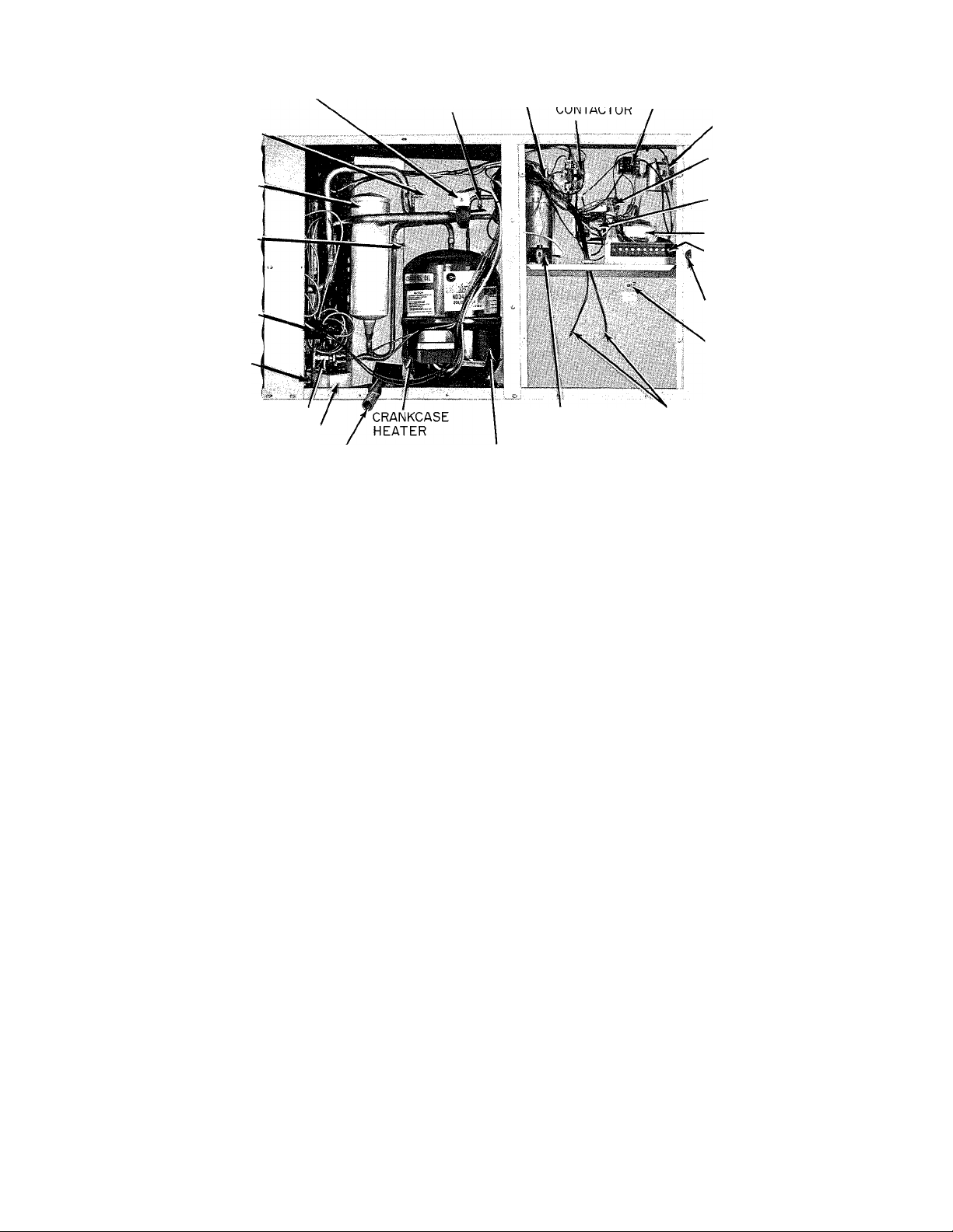
LOW-PRESSURE
SERVICE FITTING
ACCUMULATOR
ACCUMULATOR
FUSIBLE
PLUG
DEFROST
THERMOSTAT
METERING
DEVICE
REVERSING VALVE
ASSEMBLY
HIGH-PRESSURE
SERVICE FITTING
CAPACITOR(S)
(COMPRESSOR a
FAN MOTOR)
BLOWER MOTOR
RELAY
BLOWER MOTOR
CAPACITOR
DEFROST
RELAY
DEFROST
TIMER
TRANSFORMER
LOW-VOLTAGE
TERMINAL
BOARD
LOW-VOLTAGE
INLET HOLE
CHASSIS
GROUND
CONNECTION
LOW-PRESSURE SWITCH
INDOOR COIL DRAIN PAN
4 MPT PLASTIC DRAIN FITTING
^(SHIPPED TAPED INSIDE
COMPRESSOR COMPARTMENT)
COMPRESSOR
Figure 8—Partial Side'View With Compressor & Control
Access Panels Removed (Model 542E036, 208V-230V—1)
During the heating defrost cycle, defrost water from the
melting ice on the outdoor coil flows through the holes in the
heat pump base directly below the outdoor coil. When using
a field-supplied drain pan to catch the defrost water, be sure
that this pan is at least 2 inches high and extends at least 2
inches beyond the width and length of the unit.
If the installation requires draining the condensate and/or
defrost water away from the unit, connect a drain tube(s),
using a minimum of 7/8-inch OD copper tubing, 3/4-inch
galvanized pipe, or 7/8-inch plastic pipe. Do not undersize the
tuhe(s). Pitch the drain tube(s) downward at a slope of at
least 1 inch in every 10 feet of horizontal run. Be sure to
check the drain tube(s) for leaks.
Condensate and defrost water can be drained directly onto
the roof in rooftop installations (where permitted) or onto a
gravel apron in ground-level installations. When using a
gravel apron, make sure it slopes away from the unit.
III. DUCT CONNECTIONS
Model 542E has duct flanges on the supply- and return-air
openings on the side of the unit. See Figure 3 for connection
sizes and locations.
Model 542D has duct flanges on the supply- and return-air
openings on the bottom of the unit. See Figure 4 for connec
tion sizes and locations.
WARNING: The design and installation of the duct system
must be in. accordance with the standards of the National
Fire Protection Association for installation of nonresidencetype air conditioning and ventilating systems, NFPA No.
90; or residence-type, NFPA No. 90B; and/or local codes and
ordinances.
Adhere to the following criteria when selecting, sizing, and
installing the duct system:
1. Select and size ductwork, supply-air registeis, and
return-air grilles according to ASHRAE recommenda
tions and as presented in BDP training materials.
QUICK-START PTC
THERMISTOR
■HIGHVOLTAGE
PIGTAIL
LEADS
A79243
CAUTION: When the duct system fastening holes are being
drilled into the side of Model 542E instead of the unit duct
flanges, use extreme care to avoid puncturing the coil or coil
tubes.
2. Use a flexible transition between rigid ductwork and
unit to prevent transmission of vibration. The transi
tion may be screwed or bolted to duct flanges. Use suita
ble gaskets to ensure a weather and airtight seal.
NOTE: When using a supplemental electric heater, main
tain a minimum clearance of one inch to combustible
materials for the first 36 inches of duct and use fireproof
material for the transition between the ductwork and unit
supply-air duct flange. When using flexible duct (which is
not heat resistant), use a 36-inch long sheet metal duct be
tween the supply outlet and the flexible duct. Observe the
warning on the unit rating plate.
3. Install an external, field-supplied air filter(s) in the
return-air ductwork where it is easily accessible for ser
vice. Recommended filter sizes are shown in Table I.
(Model 542D has factory-supplied air filters.)
4. Size all ductwork for required indoor airflow of heat
pump being installed. This airflow will be adequate for
safe electric heater operation (except when using 20KW heater with 030-size unit airflow must be at least
1000 fU/min). Avoid abrupt duct size increases or
decreases.
5. Adequately insulate and weatherproof all ductwork
located outdoors. Insulate ducts passing thru an uncon
ditioned space, and use a vapor barrier in accordance
with the latest issue of SMACNA and NESCA minimum
installation standards for heating and air conditioning
systems. Secure all ducts to the building structure.
6. Flash, weatherproof, and vibration-isolate all openings
in building structure in accordance with local codes and
good building practices.
Page 6

HIGH-VOLTAGE
PIGTAIL LEADS
BLK
BLK ^
RED
/r
/ r-Tok F1ELD-SUPPL1E(
3-PHASE
UNITS ONLY
-FIELD SPLICE
SWITCH
1
POWER
SUPPLY
A79244
Figure 9—Field High-Voltage Connections
IV. ELECTRICAL CONNECTIONS
WARNING: The unit cabinet must have an uninterruptedj
unbroken, electrical ground to minimize the possibility of
personal injury if an electrical fault should occur. This
ground may consist of electrical wire connected to the unit
ground lug in the control compartment, or conduit approved
for electrical ground when installed in accordance with the
National Electrical Code and local electrical codes. A failure
to follow this warning could result in the installer being lia
ble for the personal injury of others.
CAUTION: A failure to follow these precautions could result
in damage to the unit being installed;
1. Make all electrical connections in accordance with the
National Electrical Code and local electrical codes
governing such wiring.
2. Use only copper conductor for connections between the
field-supplied electrical disconnect switch and the unit.
DO NOT USE ALUMINUM WIRE.
3. Ensure that high-voltage power to the unit is within the
operating voltage range indicated on the unit rating
plate. On 3-phase units, ensure that phases are balanced
within 2%. Consult the local power company for correc
tion of improper voltage and/or phase balance.
4. Insulate low-voltage wires for the highest voltage con
tained within the conduit when low-voltage control
wires are run in the same conduit as high-voltage wires.
5. Do not damage internal components when drilling thru
any panel to mount electrical hardware, conduit, etc.
6. Make sure that the service conductors used between the
electrical service panel and the field-supplied electrical
disconnect switch do not have a current capacity less
than the copper wire specified, and do not create a total
voltage drop in excess of 2% of the rated voltage of the
unit.
NOTE: When using aluminum conductor from the electrical
service panel (power supply) to the disconnect switch (where
local codes permit the use of aluminum wire), make the con
nections in accordance with the National Electrical Code.
Prepare all aluminum wire immediately before installation
by “brush-scratching” the wire, then coating the wire with a
corrosion inhibitor (such as Pentrox A). Be sure that the
entire connection is completely covered to prevent an
electrochemical reaction that will cause the connection to
fail very quickly. Do not reduce the effective size of the wire
by cutting off strands to fit the wire into a connector. Always
use properly sized connectors.
A. High-Voltage Connections
The unit must have a separate electrical service with a fieldsupplied, waterproof fused disconnect switch at, or within
sight of, the unit. Refer to the imit rating plate for max
imum fuse size and minimum circuit amps (ampacity) for
wire sizing. Tables II and III show recommended wire sizes
and lengths based on rating plate data.
The field-supplied disconnect switch box may be mounted on
the unit over the high-voltage inlet hole in the control cor
ner panel. See Figure 3 or 4. Be sure that the disconnect box
does not interfere with the removal of the blower access
panel.
Proceed as follows to complete the high-voltage connections
to the unit:
1. Connect ground lead to chassis-ground connection when
using a separate ground wire.
2. Connect high-voltage power leads to unit high-voltage
pigtail leads. Single-phase units have two black pigtail
leads. Three-phase units have two black and one red pig
tail lead. See Figure 8, Figure 9, and unit wiring label.
Use a suitable wire splice connector or wirenut to make
each high-voltage connection. Tape each completed con
nection.
B. Special Procedures for 208-V Operation
WARNING: Make sure that the power supply to the unit is
switched OFF before making any wiring changes.
When operating sizes 018 thru 036 single-phase units or
sizes 036 thru 060 208/230-volt three-phase units at 208
volts, disconnect the red transformer-primary lead from the
contactor. See the unit wiring label and Figure 8. Remove
the tape and cover from the terminal on the end of the blue
transformer-primary lead. Save the cover. Connect the blue
lead to the contactor terminal from which the red lead was
disconnected.
Using the cover removed from the blue lead, insulate the
loose terminal on the red lead. Wrap the cover with electri
cal tape so that the metal terminal can not be seen.
NOTE: If a blower motor speed is changed, insulate all
unused motor leads following the same procedures described
for the transformer leads.
C. Low-Voltage Connections
The recommended heat pump room thermostats for heat
pump operation with or without supplemental electric
heaters are P/N 34427DP115 (subbase included) for auto
matic system changeover and P/N 34427DP118 (subbase
included) for manual system changeover. These thermostats
have an emergency heat (EM. HT.) switch and red indicator
light.
Heat pump room thermostat P/N 34427DP87 (subbase
included) can be used for heat pump operation without sup
plemental electric heaters. This thermostat provides for
manual system changeover and does not have an emergency
heat switch.
NOTE: When a supplemental electric heat package is being
used, see the Installation Instructions packaged with the
heater to complete system low-voltage wiring connections.
Locate the room thermostat on an inside wall in the space to
be conditioned where it will not be subjected to either a cool
ing or heating source, or direct exposure to sunlight. Mount
the thermostat 4 to 5 feet above the floor.
Use No. 18 AWG color-coded, insulated (35°C minimum)
wires to make the low-voltage connections between the ther
mostat and the unit. If the thermostat is located more than
100 feet from the unit (as measured along the low-voltage
wires), use No. 16 AWG color-coded, insulated (35°C
minimum) wires.
A grommeted, low-voltage inlet hole is located in the panel
adjacent to the control access panel. See Figure 3 or 4. Run
the low-voltage leads from the thermostat, thru the inlet
hole, and to the low-voltage terminal board. See Figure 8.
Connect the low-voltage thermostat leads to the terminal
-6-
Page 7

Figure 10—Field Low-Voltage Connections Using Room
Thermostat P/N 34427DP115 or P/N 34427DP118
HEAT PUMP
LOW-VOLTAGE
TERMINAL
BOARD
Figure 11—Field Low-Voltage Connections Using Room Thermostat P/N 34427DP87
A79245
АГ9246
board as shown in Figure 10 or 11, depending on which
recommended room thermostat is being used.
NOTE: When using thermostat P/N 34427DP115 or
34427DP118, run a thermostat lead from each of the 10
thermostat terminals. Insulate the end of the leads that do
not have a connection point in the unit.
D. Heat Anticipator Settings
The recommended room thermostats have a fixed heat antic
ipator for heat pump heating. When using an accessoryelectric heater to provide supplemental heat and emergency
heat capability for the system, see the Installation Instruc
tions packaged with the heater for setting the adjustable
second-stage heat anticipator.
V. PREPARING UNIT FOR STARTUP
WARNING/DANGER: A failure to observe the following
warnings could result in serious personal injury:
1. Follow recognized safety practices and wear protective
goggles when checking or servicing refrigerant system.
2. Do not operate compressor or provide any electric power
to unit unless compressor terminal cover is in place and
secured.
3. Do noT remove cdmpro.s.--or terminal cowr uniil all
elecrrical sources have bet ;n disconnec red.
4. Relieve all pressure from system before touching or dis
turbing anything inside terminal box if a refrigerant
leak is .suspected an)und compressor tcriViinal.s.
0. Do tiot use a torch to remove any coiitporienr. 8\-.41е7П
contains oil and refrigerant under pressure. To remove a
component, wear protective goggles and proceed as
follows:
a. 8hur oil' electrical ]io\ver t() unit.
b. Relieve all pre.s.suri' t'roui .system.
c. Cut component connecting tubing with tubing cut
ter and remove component from unit.
d. Carefully unsweat remaining tubing stubs when
necessary. Oil can ignite when exposed to torch
flame.
A. Prestartup Procedures
Proceed as follows to inspect and prepare the unit for initial
startup:
1. Remove all access panels.
2. Remove stryofoam shipping blocks from between com
pressor and divider panel, and between accumulator and
divider panel
-7-
Page 8

Figure 12—Removing Belt-Drive Blower Shipping Bracket
A80089
3. Read the following instructions on all WARNING,
CAUTION, and INFORMATION labels attached to
unit; for example, blower rotation labels, etc.
4. Refer to Figure 12 and remove shipping bracket from
belt-drive blower units as follows:
a. Locate shipping bracket mounted on blower
housing.
b. Remove two bracket mounting screws from each
side of blower housing.
c. Remove rubber knob and shipping nut from adjust
ing bolt.
d. Discard shipping bracket and nut, then replace rub
ber knob on end of adjusting bolt.
e. See Section VI, part C, to adjust indoor airflow.
5. Make the following inspections:
a. Inspect for shipping and handling damages such as
broken lines, loose parts, disconnected wires, etc.
b. Inspect for oil at all refrigerant tubing connections
and on unit base. Detecting oil generally indicates a
refrigerant leak. Leak-test all refrigerant tubing
connections, using electronic leak detector, halide
torch, or liquid-soap solution. If refrigerant leak is
detected, see “Refrigerant Leaks” in the next part of
this section.
c. Inspect all field and factory wiring connections. Be
sure that connections are completed and tight.
d. Inspect coil fins. If damaged during shipping and
handling, carefully straighten fins with a fin comb.
6. Verify the following conditions:
a. Make sure that outdoor fan blade is correctly
positioned in fan orifice. Blades should clear motor
by H4 inch.
b. Make sure that air filter (s) is in place.
c. Make sure that condensate drain trap is filled with
water to ensure proper drainage.
d. Make sure that all tools and miscellaneous loose
parts have been removed.
7. Replace all access panels. (Unit is now ready for initial
startup.)
B. Refrigerant Leaks
Proceed as follows to repair a refrigerant leak and to charge
the unit:
WARNING: Never attempt to repair a soldered connection
while the refrigerant system is under pressure. Severe bodi
ly injury may result. Always wear protective goggles when
servicing the refrigerant system.
1. Locate leak and ensure that refrigerant system pressure
has been relieved.
2. Repair leak, following accepted practices.
NOTE: Install a filter-drier whenever the system has been
opened for repair.
3. Add a small charge of R-22 refrigerant to system and
leak-test unit.
4. Evacuate refrigerant system if additional leaks are not
found.
5. Charge unit with R-22 refrigerant, using a volumetric
charging cylinder or accurate scale. Refer to unit rating
plate for required charge. Be sure to add extra
refrigerant to compensate for the internal volume of the
filter-drier.
NOTE: See Section VI, part B, for checking and adjusting
refrigerant charge.
VI. STARTUP AND ADJUSTMENTS
CAUTION: Complete the required procedures given in Sec
tion V, “Preparing Unit for Startup,” before starting the
unit.
Do not jumper any safety devices when operating the unit.
Do not operate the compressor until electric power has been
applied to the heat pump for a minimum of 4 hours to ensure
that the oif-cycle crankcase heater has sufficiently warmed
the compressor oil to free most of the accumulated
refrigerant.
Do not rapid-cycle the compressor. Allow 5 minutes between
“on” cycles to prevent compressor damage.
A. Checking Unit Operation
Start and check the unit for proper operation as follows:
1. Place room thermostat SYSTEM switch in OFF posi
tion. Observe that indoor blower motor starts when
FAN switch is placed in ON position and shuts down
when FAN switch is placed in AUTO position.
-8-
Page 9

Air Temp at
Indoor Coil
Inlet |°F DB)
65
70
75
TABLE IV-HEATING PERFORMANCE PRESSURES
Pressure
Designation
(Psig)
High Side 250 229
Low Side 69 59
High Side 268
Low Side 70
High Side 280 256 233 211 190 172 155 140 266
Low Side
60 50 40 30 20 10 0
243 220 199 180 162 147 134
60 50 42 34 26 19 15
71 61 51 43 35 27 20 16 73 62 52 43
54ZED24 542E030
Air Temperature at Outdoor Coil
F°DB
-10
209 190 172 155 140 127
49 41 33 25 18 14 71
238 218 201
251 231 211
Air Temperature at Outdoor Coii
60 50 40 30
184 169 155 144 134
50 41 32
60
72 61
246
195 179
51 42
207 190 176 162 151 261
226
20
°FDB
10 0 -10
24
18 13 64 52
165
33 25 19 14 65 53
34 26 20 15
153 142
60 50 40 30 20
232 214 198
247
66 54 48 40 32 26
Air Temperature at Outdoor Coil °FDB
542E036
183 170 158 149 142
46 38 31 25
230 213 198 184 171
47
39
243 225
31 25 19 13
209 195 182 171 162
10
0 -10
18
161 152
19
13
14
Air Temp at
Indoor Coil
Inlet (°FDB|
65 High Side 254
70
75 High Side
Pressure
Designatiun
IPsig)
Low Side 71 62 50 42 32 24
High Side 268 250 230 205 183 169 156 144
Low Side 72 63 51 43 33 25
Low Side 73
60 50 40 30 20 10
234
283 266 243 218 194 180 166 153
64
542E042 542E048
Air Temperature at Outdoor Coil °FDB
0 -10
216 193 171 159 148
52 44 34 26 19 14
136
18 14 64
18
60 50 40
262
278
14
290 266
65 57 49
66 58
TABLE V-COOLING PERFORMANCE PRESSURES
Air Temp at
Indoor Coil
Inlet (°FWB)
Air Temp at
Indoor Coil
Inlet l°FWBI
55
60 High Side
65 High Side 173 187 201 215 231 246 263 280 298
70 High Side 177 191 205 220 235 251 268 285 303 322 193 208 223 240
75 High Side 181 196 210 225 240 256 273 290 308 327 198 214 229 246
Pressure
Designation
IPsigI
55 High Side 157 174 190 207 224 240
Low Side 58 59 60 61 62 63 64 66 67 68 60 62 63 65
60 High Side
Low Side
65 High Side 168 185 200 216 232 247 264 282 298 317 157 173 188
Low Side 70
70 High Side 173
Low Side 77 78 79 80 81 82 83 84 86 87
75 High Side
Low Side 84 85 86 87 88 90 91 93 94 95
Pressure
Oesignation
High Side
Lew Side
Low Side
Low Side 68 69
Low Side 72 73
Low Side 76 77 79 81
65 70 75 80 85 90 95
195
162 179
64 65 66 67 68 69 70 71
71 72
191
206 223 239 253 270
175 192 209
(Psig)
55 70 75 80 85 90 95 100 105 110 65 70 75 80
165 179 192 206 222
60 62 63 65 67 68 70 72 74 75 61 62 63 65 66 68
169 183 196
64 66 67 69 70 72 74 75 77 79 65 66 67 69 70
71 73 74 76
75 77
542E024
Air Tem p at Outdoor Coil |°F DB|
244
212 228
75
73
227 242
260 278
542E042
Air Tem p at Outdoor Coil l°F 08) Air Tem p at Outdoor Coil l°F 08)
237 254
210
241
226
78
82 84
too
258 276 293 313
261 279 296 315
76 77 78 79 80
258
80 82 83 85 87
105 110 55 70 75
73
304 324 160 177 192 208
288
294 315
270
275 293 312
78
86
336
289 308
317
79 81 83 69 70 71 73
87
91 77
89
150 166
153
169
74 63 65 66 68 70 72 75
67 69 70 72 74 76 79 81 83 85 71 73
70 72 74 76 78 80 83 85 87 89 74 76
164
180 196 212 228
74 76 78 80 82 84 87 89 91 93 79 81
178 192
197
183
188 203 218
74 75 77 78 80 82
73
78 80 81
Air Temperature at Outdoor Coll
20 10 0
30
237 214 193
48 40
56
251 226
242 220 201
50 42
Air Tem p at Outdoor Coil (°FDBI
80
196 212 226 246 264 282 302 182
181
185 200 216 230 250 268 286 306 185 199
204
207 224 238 255 272 291 308 330
212 229
235 249 266 283 302 320 340
174 158
204 184 166
41 34
542E030
85 90 95 100 105 110 55 70
67
69
235 255 273
220
224 240 259 277 295
244 264 282 300 320 196 212 228
542E048
85 90 95 100 105 110
243 260
72 74 76 78 80 63
74
76 78
254 271 288 307 326 345 191
260 277 294 312 332 350 198
83 84 86 88 90 92
"FOB
-10 60 50
144 134 268
33 26 19
27 20 13
184 169
35 28
71
73 75
77
70 72 74 76 59 61
277
296 314
80 82 84 67
84
13 66
154 146
21 14 68
79 81 69
291 311
86 88
284 252
158 298
77 67 69 70 72
188 203 219
192 207 223 239
315
65 70 75 80 85 90
176 189 202
335 180 193
185 198
71 73
76
67
196 211 227 242 259 276
65 66 6/ 68 /0
69 70
205 219
212
77 79 80 82
5420060. A 542E060
Air Temperature at Outdoor Coil °FDB
40 30 20 10 0 -10
238 210 186 166
47
56
57 48 40 32 25 19 13
268 238 212 190
58 49
75 80 85 90 95 100
215 231 246 263 280 298 316 336
71 72 74 76
74 76 78 80 81 83
77 79 81 83
83 84 86 88 89 91
62 63 65 6/ 68
207 222 237 254 270 287 305
212 227 242 259 275 292 31U
74 /5
227 242 258 274 292 310 328 346
39
224
198 178
41
54ZE035
Air Tem p at Outdoor Coii l°F OBI
74 75 76 78 79 81
235 251
255 273 290 308 326 346
244 260 278 296 314 332 352
5420060 S 542E060
Air Tem p at Outdoor Coil (°F0BI
217 233 249 266 283 300 320
/1
/2
234 250 266 283 301 319 338
II
151 142
32 24 19 13
164 154 146
1/4 162
25 20 14
33
294 312 332
77
80 82 83
79
285 303 321 341
268
84
86
95 100 105 110
/0 /2 /4
/1 /3 /5 n
/4
/6 /8 80
/5
80 81 83 85
/9
84 85 8/ 89 91
136
156
105 110
85 86
88 89
93 9b
324
329
2. Place SYSTEM switch in COOL position and FAN
switch in AUTO position. Set thermostat cooling control
below room temperature to start cooling cycle. Observe
that compressor, outdoor fan, and indoor blower motors
start. Observe that unit shuts down when control set
ting is satisfied. Wait 5 minutes for pressures to
equalize.
3. Place SYSTEM switch in HEAT position, and leave
FAN switch in AUTO position. Increase thermostat
heating control setting gradually until thermostat
“calls” for heat. Observe that compressor, outdoor fan,
and indoor blower motor start. If supplemental electric
heater is being used in the system, increase thermostat
heating control setting an additional 6 degrees. Observe
that the supplemental electric heater energizes. Set
control setting below room temperature, and observe
that heater deenergizes and that heat pump shuts down.
4. If supplemental electric heater is being used in the
system, leave FAN switch in AUTO position, SYSTEM
switch in HEAT position, and move emergency heat
switch from NORM, position to EM. HT. position. Set
thermostat control setting above room temperature to
start heating cycle. Observe that all supplemental
electric heat is energized, that indoor blower motor
starts, that emergency heat indicator bulb lights, and
that compressor and outdoor fan do not start. When con
trol setting is satisfied, observe that heater deenergizes
and that blower motor stops; however, indicator light
should remain on as long as emergency heat switch is in
EM. HT. position.
5. If autochangeover thermostat P/N 34427DP115 is
being used, place both SYSTEM and FAN switches in
AUTO position. Observe that heat pump operates in
heating mode when heating control selector is set above
room temperature, and operates in cooling mode when
cooling control selector is set below room temperature.
B. Checking and Adjusting Refrigerant Charge
The refrigerant system is fully charged with R-22
refrigerant, tested, and factory-sealed. For most applica
tions, the factory charge is the correct amount for the best
performance; however, this charge rnay require a slight
adjustment to attain rated performance.
-9-
Page 10

NOTE: Adjustment of the refrigerant charge is not required
unless the unit is suspected of not having the proper charge.
An operating pressure/temperature tag is fastened inside
the compressor compartment. (Also see Tables IV and V.)
Use this tag to approximate the charge if ARI rating condi
tions can not be obtained, when evaluating the refrigerant
charge by checking operating pressures and temperatures.
This method of evaluating ensures that an optimum
refrigerant charge is in the system when the system condi
tions and components are normal; however, adjusting the
refrigerant charge does not solve or fix system abnor
malities.
The amount of refrigerant charge affects how efficiently and
economically the unit operates. An overcharged or under
charged unit leads to diminished efficiency, high operating
costs, and the possibility of premature compressor failure.
CÀUTION; When evaluating the refrigerant charge, an
indicated adjustment to the specified factory charge must
always be very minimal. If a substantial adjustment is indi
cated, an abnormal condition exists somewhere in the
system; such as insufficient airflow across either coil or both
coils.
When checking the refrigerant using the temperature/pres-
sure evaluation method, adhere to the following criteria:
1. Check refrigerant charge in cooling mode when outdoor
temperature is above 65°F.
2. Check refrigerant charge in heating mode when outdoor
temperature is below 65°F.
3. For best results, do not operate unit continuously for
more than 10 minutes if for any reason charge must be
checked in opposite mode above or below 65°F.
Proceed as follows to evaluate the system performance and
refrigerant charge:
1. Remove caps from low- and high-pressure service fit
tings. See Figure 8.
2. Attach low- and high-side pressure gauge hoses to lowand high-pressure service fittings, respectively. Hoses
must have valve core depressors. Gauges must be cali
brated for accuracy.
3. Set room thermostat below room temperature to start
cooling operation or above room temperature to start
heating operation, depending on outdoor temperature.
Allow unit to operate until conditions stabilize and
pressures level out.
4. Determine and record these conditions:
a. Low- and high-side pressures.
b. Dry-bulb temperature of inlet air at outdoor coil.
c. Temperature of inlet air at return-air grille—creí
bulb if operating in cooling mode or dry bulb if operat
ing in heating mode.
5. Evaluate system performance and refrigerant charge by
comparing recorded reading with operating pres
sure/temperature tag.
6. Make slight adjustment to refrigerate charge when
necessary.
NOTE: If the problem causing the inaccurate readings is a
refrigerant leak, see Section V, part B, of these instructions.
high- and low-speed connection (except for 460-V motors
which have only a high-speed connection).
The system airflow for all direct-drive units (except 460-V)
can be changed, when necessary, by changing the blower
motor speed connection from the factory setting to the
unused speed connection. The factory setting is indicated on
the unit wiring label. For operation of units designed for
208-V and 230-V operation, a blower motor speed connection
may need to be changed. See unit wiring label. See Section
IV, part B, for the procedure.
Model 542D060 and 542E060 3-phase units have belt-drive
blower motors. The system airflow for these units can be
changed, when necessary, by adjusting the blower-motor
pulley as follows:
CAUTION: Increasing the hlower speed places a heavier
load on the motor and increases the current. Do not exceed
the rated full load amperage indicated on the rating plate of
the blower motor.
1. Turn off power at disconnect switch.
2. Relieve belt tension, then remove drive belt from motor
pulley.
3. Loosen setscrew in movable flange on motor pulley and
turn flange either in to increase airflow or out to decrease
airflow.
4. Make sure that setscrew is over flat surface on pulley
hub and tighten setscrew.
5. Replace belt and adjust belt tension for approximately
one inch of sag under normal finger pressure midway
between pulleys.
Tables VI and VII show the air delivery performance at
various external static pressues. Determine the airflow for
the system being installed as follows;
1. Start the unit and measure static pressure in duct
system at unit.
2. Refer to Table VI or VII and determine airflow at static
pressure measured.
NOTE: Be sure that all supply- and return-air grilles are
open, free from obstructions, and adjusted properly.
When using an accessory electric heater, the system airflow
can also be determined by measuring the temperature rise
through the unit, then using the following formula:
KW
AIRFLOW (ftVmin) =
TR
xY
where,
KW = Heater nominal KW at 240 or 480V
TR = Measured temperature rise
Y =
200V 208V
2195
NOTE: Value Y varies with the operating voltage at the heater.
Interpolate to determine the value of Y for voltages not
shown.
2374 2655
220V 230V 240V
440V 460V
2902
480V
3160
C. Indoor Airflow & Airflow Adjustments
CAUTION; The recommended indoor airflow is 350 to 450
ft®/min per each 12,000 Btuh of rated unit capacity. Inade
quate airflow can cause unsatisfactory operation and per
formance.
Model 542E, sizes 024 thru 048, and single-phase 060-size
units have direct-drive blower motors. All motors have a
CAUTION: When using an accessory electric heater, the
system airflow must be sufficient to prevent the heater limit
switches from tripping off. W'hen using the 20-KW single
phase heater, the system airflow must be at least 1000
ft^/min.
-10-
Page 11

TABLE VI-AIR DELIVERY (FtVMin) AT INDICATED EXTERNAL STATIC PRESSURE & VOLTAGE*
Blower
Model
542E024 Low
542E030
542E036
542E042 Low
542E048
542E060
(Single-
Phase
Units)
* Deduct field-supplied air filter pressure drop & heater loss (when used) to obtain available external static pressure for ducting,
t Heating airflow values are with a dry coil. Cooling airflow values are with a wet coil.
NOTE: Shaded portions of this table fall below 350ft^/min per 12,000 Btuh of rated cooling capacity. Indoor coil icing may ocur at airflows
below this point. Dashes are used in those areas of the table that fall beyond the capability of the indoor blower motor.
Motor
Speed
High 208 Heating
Low
High
Low
High 208 Heating 1685
High 208 Heating
Low
High 208 Heating
Low 230 Heating
High 230 Heating 2700
Opera
ting
Voltage
208
230
230
208
230 Heating
208 Heating
230 Heating
208 Heating
230 Heating
230 Heating
208 Heating
230 Heating
230 Heating
208 Heating
230 Heating
230
460 Heating
Applica-
Heating
Cooling
Heating
Cooling
Cooling
Heating
Cooling
Heating
Cooling
Cooling
Cooling
Cooling
Cooling 1225
Cooling
Cooling 1565
Cooling
Cooling 1370
Cooling
Cooling 1825
Cooling 2030
Cooling 1650
Cooling 1860
Cooling
Heating 2270
Cooling 2180
Cooling 2000
Cooling
Cooling 2550
tiont
External Static Pressure—Inches wc
0.0 0.1
880 835
850 810
965 925
940 900
1015 970
985
1070
1040
995
980
1070
1055
1165
1150
1260
1245
1280
1485
1400
1850
1670
1400 1360 1315
1655
1615
1895 1840 1780
2125 2065 2005
1690 1635 1575
1905 1855 1800
2005
1955 1905
2070 2000
2250
2180 2135 2085
940
1030
1000
965
945 910 865 820 760
1050 1025
1030 1005
■ 1145
1130 1105 1075 1035
1245 1225 1200 1165
1225
1235
1185 1140
1435 1380
1350 1300
1630
1510 1455
1785 1720
1615 1560
1330 1280
1610 1560 1505 1435 1360 1270
1565 1510 1450 1380 1305 1205 1050
1770 1710 1645 1570 1490 1395 1270
1970 1905 1835 1760 1675 1575 1440
1595 1535 1475 1405
1810 1755
1955 1900 1845 1780 1705
2195 2120
2110 2040 1960 1880
1930 1855
2205 2160 2110 2050 1990
2625 2550 2465 2380 2285
2475 2395 2315 2220 2120 2005
0.2
790
770
880
855 810
920 870
890 840 785
985 940 885
955 910 855 800
930 890 845 785
1125
1200 1170
1185 1135
1575
1850 1790 1725 1650 1560 1430
1925 1845 1760 1665
0.3 0.4 0.5 0.6
740
725
835
995 960 915
970 930 880 800 680
1095 1065 1020 955 845
1095
1325 1265
1250 1190
1510
1395 1325 1250 1160
1650 1575
1495 1425
M265v
1230 : 1165 : ■ 1085 955
1715 1645 1570 1480 1365
1935 1860
1510
1740 1675 1600 1510
1690 1625 1545 1445 1290
2040 1955 1870 1765 1650
1775 1690 1595 1490 1355
2030 1970 1900 1815 1700
690
675 615 550 465
780 720 655
755
815 750 685 605
1135 1080 1005 875
1080 1020 955 875
1040 985 920 850
1440 1360 1275 1160
1:205: 1130 : 1015-
1440
630 565 470
700 635
730 665 585
830 765 680
980
1125
1200
1125 1050 970
1490 1395 1280
1345 1250 1100
1775
1360 1270 : 1140
1325
1785 1685 1570
735
705
680
840 730
900
1065 970
1115
1685 1570
1,230
1625 1510
1560
1915 1830
2175 2055
0.7
575
560
660
590
560
770
1025
1045
_
■ ■
: 1140
1100
:1370
1425
1860
D. Unit Controls
All compressors have the following internal protection con
trols:
1. High-Pressure Relief VaZue—This valve opens when the
pressure differential between the low and high side
becomes excessive.
2. Compressor Ckterload—This internal overload interrupts
power to the compressor windings when either the cur
rent or internal temperature become excessive, and au
tomatically resets when the internal temperature drops
to a safe level. This overload may require up to 60
minutes (or longer) to reset; therefore if the internal
overload is suspected of being open, disconnect the
electrical power to the unit and check the circuit thru
the overload with an ohmmeter or continuity tester.
3. Low-Pressure Switch—This switch with automatic reset
interrupts the compressor control circuit when the
refrigerant high-side pressure becomes too low. It pro
tects the compressor from damage attributable to loss of
the refrigerant charge.
4. TimelTemperature Defrost System—The defrost control
system consists of a defrost timer, a defrost thermostat
switch, and a defrost relay. The system initiates defrost
cycle operation every 90 minutes if a coil icing condition
exists. See the defrost cycle sequence of operation in
Section VII.
5. Crankcase Heater—This device prevents overdilution of
compressor oil with refrigerant during shutdown
, periods, thereby extending the life of the compressor.
See the crankcase heater sequence of operation in Sec
tion VII.
6. Compressor Quick-Start Components—These components
are used with all single-phase units to improve com
pressor starting characteristics.
-11-
Page 12

TABLE VII-MODEL 542D060 & 542E060-
3-PHASE UNITS-MOTOR PULLEY SETTINGS
FOR AIR DELIVERY AT INDICATED EXTERNAL
SP & VOLTAGE WITH WET COIL
{ 208 Volts—Standard Motor Pulley & Belt |
Airflow
(Ft3/Min)
1750
1875 — — 5
2000 - - 4-1/2 3-1/2 2-1/2 2
2125 — 5
2250
1 230 Volts—Standard Motor Pulley & Belt )
Airflow
(Ft3/Min)
1750
1875 — —
2000
2125 5 4-1/2 4
2250 4-1/2 4
1 460 Volts—Standard
Airflow
(Ff3/Min)
1750 —
1875
2000
2125
2250
1 208 Volts—Optional Motor Pulley & Belt {
Airflow
(Ff3/Min)
1600 5 4
1650
1700
1750 3-1/2
1800 3-1/2
1 230 Volts—Optional Motor Pulley & Belt |
Airflow
(Ft3/Min)
16ÜÖ 5
1650 4-1/2 3-1/2 3 2 2 1-1/2 1
1700 4
1750
1800 3-1/2
1 460
Airflow
(Ff3/Min)
1600
1650
1700 3-1/2
1750
1800 3-1/2 2-1/2 2 1-1/2 1 1/2 0
1 208 Volts-Standard Motor Pu ley & Be
Airflow
(Ff3/Min)
1750
1875 5
2000
2125
2250
Airflow
(Ff3/Min)
1750 — 5
1875 5 4 3 2 1-1/2
2000
2125 3 2
2250
1 460 Volts—Standard Motor Pulley & Beit |
Airflow
(Ff3/Min)
1750 —
1875 5
2000
2125 3
2250
542E060 STANDARD DRIVE RANGE
0.30
T.O.
— —
—
4-1/2
0.40 0.45 0.50
T.O. T.O. T.O.
— —
— 5
0.30 0.40 0.50 0.60 0.70
T.O. T.O. T.O.
— — —
—
—
—
0.50 0.60 0.70 0.80
0.40
T.O. T.O. T.O. T.O. T.O.
— 4-1/2 3-1/2
4
3-1/2 2-1/2 1-1/2 1/2
— 5
—
4-1/2 4 3-1/2 3 3
4 3-1/2
—
— 5 3-1/2 3
—
5
5
—
4-1/2
4
4
3
3
0.55 0.60 0.65 0.70
T.O. T.O. T.O. T.O.
4-1/2 4 3-1/2 3
3-1/2 3-1/2
Victor Pulley & Belt |
TO.
4
4
3-1/2
3
2 1
4-1/2 4 3-1/2
3
T.O.
3
3
2
2 1
542E060 OPTIONAL DRIVE RANGE
0.20 0.25 0.30 0.35 0.40 0.45
T.O.
4-1/2 3-1/2 3 2 1-1/2
4
0.20 0.25 0.30 0.35 0.40
T.O.
T.O. T.O.
4
Volts—Optional Motor Pulley & Beit |
0.20 0.25
T.O. T.O. T.O. T.O. T.O. T.O. T.O.
4
3-1/2 3 2-1/2 2 1-1/2 1
3-1/2
T.O. T.O.
T.O.
3
2-1/2
3
3
4 3
2-1/2 2 1-1/2 1 1/2
3
2-1/2 2 1-1/2 1
3
3
2-1/2 2 1-1/2 1 1/2
3
2-1/2 2 1-1/2 1 1/2
3
2-1/2 2 1 1 1/2
3
2-1/2
3
2-1/2 2 1-1/2 1 1/2
2 1-1/2 1 1/2 0
2-1/2 2 1-1/2 1
2 2 1 1 1/2
0.30 0.35 0.40 0.45 0.50
2 1-1/2
T.O.
T.O.
2
T.O.
542D060 STANDARD DRIVE RANGE
0.10 0.20 0.30 0.40 0.50 0.60 0.70
T.O. T.O. T.O.
—
4
2-1/2 2 1 1/2 0
2
0.10 0.20 0.30 0.40
T.O. T.O. T.O. T.O. T.O.
4
2
0.10
T.O. T.O.
4-1/2
4
2
3-1/2
4
3-1/2 3 2 1-1/2 1/2 0
2-1/2
1
3
1-1/2 1-1/2
1
0.30 0.40 0.50 0.60
0.20
T.O. T.O. T.O. T.O. T.O.
5
3-1/2
2-1/2 1-1/2 1 1/2
3
1-1/2 1 0
2
1-1/2 1/2 0
T.O.
3
2 1 1
1/2
1/2 0 —
— — —
230 Volts—Standard Motor Pulley & Belt |
4
3 2-1/2 1-1/2 1
2 1-1/2 1
3-1/2
4
2-1/2 2 1 1/2
■t 1
T.O. T.O.
2 1-1/2 1
0,50
0
2-1/2 1-1/2 1
—
0.90
T.O.
2-1/2 2
2-1/2 1
2-1/2 2
0.80 0.90
T.O. T.O.
1-1/2 1/2
T.O. T.O.
1-1/2 1
1-1/2 1
0.45 0.50
T.O. T.O.
—
0.60 0.70
T.O.
2-1/2
3
2 1-1/2
2
0.50
1 1/2
1/2
T.O.
0 —
T.O.
1 0
0
—
_
0.70
—
— -
1/2
—
—
—
—
—
—
—
—
_
—
NOTES:
1. Values shown for Model 542E'are without air filter.
Values shown for Model 542D are with faotory-supplied 1-inch air filters. Use values shown for Model
542D when using the accessory field-installed down
flow plenium with Model 542E.
2. T.O. = Blower motor pulley turns open.
3. Dashes indicate portions of thè table that are beyond
the drive range.
4. Optional drive for Model 542E060: motor pulley P/N
50611B6 & belt P/N 94006
5. Motor pulley factory setting is two turns open.
7. Outdoor Fan Thermostat—This control, which is
featured on all 3-phase units, maintains the proper
cooling mode condensing temperature by switching the
outdoor fan motor to high- or low-speed operation. Low-
2
1
speed fan operation permits low-ambient cooling opera
tion down to 40°F outdoor temperature.
VII. SEQUENCE OF OPERATION
Do not leave the installation until the heat pump has been
observed throughout one or two complete cycles. The
installer should make certain during this time that all com
ponents are operating in correct sequence.
The sequences of operation described in this section pertain
.to size 036, 042, and 048 208/230-volt, 3-phase units;
however, the sequence of operation of all units is very simi
lar. Refer to the line-to-line wiring diagram in Figure 13.
NOTE: Although the actual unit wiring may vary slightly
from that shown in Figure 13, the sequence of operation will
not be affected. The sequences of operation described in this
section pertain to a typical system using room thermostat
P/N 34427DP115 or P/N 34427DP118 for system control,
and using an accessory electric resistance heater for supple
mental heat.
NOTE; The indoor blower motor will operate continuously,
regardless of the room thermostat SYSTEM switch position,
when the FAN switch is in the ON position. The ON position
of the FAN switch keeps the circuit through blower relay
coil 2A closed and the coil energized. When the FAN switch
is in the AUTO position, the blower operates only when the
system is started by the room thermostat demand for heat
ing or cooling.
A. Crankcase Heater Operation
Compressor crankcase heater llA is connected across nor
mally open cmpressor contactor 2D contacts between 13 and
23. When electric power is supplied to the heat pump, and
the unit is not operating in either the heating or cooling
mode, a completed circuit between power legs LI and L3 per
mits current to flow through one leg of compressor motor 3F
windings and through crankcase heater 11 A. The high
electrical resistance of the crankcase heater causes the
heater to heat up, while the compressor motor windings
serve only as a means of completing the circuit between LI
and L3.
When the heat pump receives a “call” for either heating or
cooling, normally open compressor contactor 2D contacts
between 13 and 23 close. (See heating and cooling sequences
of operation in this section.) Electric current, which always
follows the path of least resistance, flows through the closed
contacts and through both compressor motor 3F and outdoor
fan motor 3D1. The crankcase heater, which offers a much
higher electrical resistance than the two motors, receives
virtually no electrical current as long as the contactor is
energized.
-12-
Page 13

B. Cooling Operation
With the room thermostat SYSTEM switch in the COOL
position and the FAN switch in the AUTO position, the cool
ing sequence of operation is as follows:
When the room temperature rises to within 2 degrees of the
cooling control setting of room thermostat, the thermostat
cooling operation bulb tilts and connects thermostat ter
minal R to thermostat terminal O. This completed circuit
through the thermostat completes the circuit through unit
terminal O. Reversing valve solenoid coil 5B and outdoor fan
relay coil 2C are now connected across the 24-volt secondary
of unit transformer IB.
Energized solenoid coil 5B switches the reversing valve from
the normal heating mode position to the cooling mode posi
tion. Energized outdoor fan relay coil 2C closes its set of nor
mally open contacts between 1 and 3, and opens its set of
normally closed contacts between 1 and 2, permitting two-
speed outdoor fan motor 3D1 to operate on either high or low
speed, depending on the outdoor ambient temperature.
NOTE: When the contacts of outdoor fan relay 2C are in
their normal heating mode positions as shown in Figure 13,
fan motor 3D1 operates on high speed, regardless of the out
door ambient temperature.
The heat pump is now in the “standby” condition and ready
to operate in the cooling mode when the room thermostat
“calls” for cooling.
When the room temperature rises to a point that is slightly
above the cooling control setting of the thermostat, the ther
mostat cooling bulb tilts and thermostat terminal R is auto
matically connected to thermostat terminals G and Y. These
completed circuits through the thermostat connect indoor
blower relay coil 2A (through unit terminal G) and com
pressor contactor coil 2D (through unit terminal Y) across
the 24-volt secondary of transformer IB.
The set of normally open contacts of energized relay 2A be
tween 1 and 3 closes and completes the circuit through
indoor hlower motor 3D2. The motor starts instantly.
The two sets of normally open contacts of energized contac
tor 2D between 13 and 23, and 11 and 21, close and complete
the circuit through compressor motor 3F and outdoor fan
motor 3D1. Both motors start instantly. The current flow
through outdoor fan motor 3D1 also flows through fan
switching thermostat 7K, which maintains the optimum
cooling mode condensing temperature by switching the fan
motor to high- or low-speed operation, depending on the out
door ambient temperature.
The heat pump is now operating in the cooling mode. The
energized reversing valve is directing the high-temperature,
high-pressure discharge gas to the outdoor coil, where the
heat is transferred to the outdoor air.
All three energized motors continue to run and the cooling
cycle remains “on” until the room temperature drops to a
point that is slightly below the cooling control setting of the
room thermostat. At this point, the thermostat cooling bulb
tilts and breaks the circuit between thermostat R to ter
minals G and Y. These open circuits deenergize indoor
blower relay coil 2A and compressor contactor coil 2D. All
closed contacts return to their normally open position, and
all three motors stop.
The heat pump has now returned to a “standby” condition,
awaiting another “call” for cooling hy the room thermostat.
If the room temperature continues to fall, the thermostat
cooling operation bulb will tilt and break the circuit be
tween thermostat terminals R and 0. This open circuit
deenergizes reversing valve solenoid coil 5B and outdoor fan
relay coil 2C. The fan relay contacts open, and the reversing
valve switches to the normal heating mode position.
Except for the crankcase heater, all heat pump components
are now deenergized. When the room temperature rises
again and reaches the room thermostat control points, the
cooling sequence will start again. If the room temperature
continues to drop, the heat pump will remain “ofT’, and the
heating mode will not start until the room thermostat
SYSTEM switch is moved to the HEAT position (either
HEAT or AUTO when using autochangeover thermostat
P/N 34427DP115).
C. Heating Operation
With the room thermostat SYSTEM switch in the HEAT
position and the FAN switch in the AUTO position, the heat
ing sequence of operation is as follows:
When the room temperature drops to a point that is slightly
below the heating control setting of the thermostat, the
thermostat first-stage heating bulb “tilts” and thermostat
terminal R is automatically connected to thermostat ter
minals G and Y. These completed circuits through the ther
mostat connect indoor blower relay coil 2A (through unit
terminal G) and compressor contactor coil 2D (through unit
terminal Y) across the 24-volt secondary of transformer IB.
The set of normally open contacts of energized relay 2A be
tween 1 and 3 closes and completes the circuit through
indoor hlower motor 3D2. The motor starts instantly.
The two sets of normally open contacts of energized contac
tor 2D between 13 and 23, and 11 and 21, close and complete
the circuit through compressor motor 3F and outdoor fan
motor 3D1. Both motors start instantly. Outdoor fan motor
3D1 operates on high speed, regardless of the outdoor tem
perature, because outdoor fan relay contacts 2C are in their
normal heating mode positions, as shown in Figure 13. In
these normal positions, the line-voltage circuit to fan motor
3D1 is always to the high-speed motor windings, regardless
of the switching action of fan switching thermostat 7K.
The heat pump is now operating in the heating mode. The
nonenergized reversing valve is in the normal heating mode
position and the high-temperature, high-pressure discharge
gas is being directed to the indoor coil, where the heat is
transferred to the indoor air.
All three energized motors continue to run, and the heating
cycle remains “on” until the room temperature rises to a
point that is slightly above the heating control setting of the
room thermostat. If the outdoor temperature has dropped to
the point where the heating capacity of the heat pump can
not maintain the desired indoor room temperature, the
second-stage heating bulb will tilt when the indoor tem
perature continues to drop to a point that is slightly below
the factory differential setting of the room thermostat.
Thermostat terminal R is automatically connected to ther
mostat terminals W1 and W2. These completed circuits
through the thermostat connect the relay coil (or coils if
using a two- or three-bank heater) of the supplemental
electric heater across the 24-V secondary of heat pump
transformer IB. The electric heater energizes to provide sup
plemental electric heat to the system.
NOTE: See the Installation Instructions packaged with the
electric heater for a more comprehensive description of the
electric heater sequence of operation.
When the room temperature rises to a point that is slightly
above the second-stage control setting, the second-stage
heating bulb will tilt and break the circuit between ther
mostat terminal R to terminals W1 and W2. The supplemen
tal electric heat deenergizes. When the room temperature
continues to rise to a point that is slightly above the heating
control setting of the room thermostat, the first-stage heat
ing bulh tilts and breaks the citcuits between thermostat
terminal R to terminals G and Y. These open circuits
-13-
Page 14

deenergize indoor blower relay coil 2A and compressor con
tactor coil 2D. All closed contacts return to their normally
open position and all three motors stop.
The heat pump has now returned to a “standby” condition
awaiting another “call” for heating by the room thermostat.
Except for the crankcase hater, all heat pump components
are now deenergized. If the room temperature continues to
rise, the heat pump will remain “off” and the cooling mode
will not start until the room thermostat SYSTEM switch is
moved to the COOL position (either COOL or AUTO when
using autochangeover thermostat P/N 34427DP115).
D. Defrost Cycle
The defrost control circuit consists of defrost timer 3M,
defrost thermostat switch 7M, and defrost relay 2P. The
defrost timer is factory-set for 90-minute intervals of
elapsed running time, which results in optimum heating
mode efficiency for most installations; however, the adjusta
ble cam can be reset for a 30-minute interval when abnormal
climatic conditions dictate. These conditions include
excessive outdoor humidity at low outdoor temperatures or
any condition that results in frequent incomplete de
frosting.
CAUTION: Kever adjust the factory-set 9()-minute interval
unless an observed defrosting problem exists. An occasional
deposit of frost on the outdoor coil, after a full 10-minute
time-terminated defrost cycle, does not indicate that a
problem exists. Frequent deposits of frost on the outdoor coil
that occur throughout a wide range of outdoor temperatures
indicate that a problem does exist.
With the heat pump operating in the heating mode, the
defrost cycle sequence of operation is as follows:
Defrost thermostat 7M switches to the closed position when
the outdoor coil refrigerant temperature drops to approx
imately 30°F. When defrost timer 3M completes 90 minutes
of elapsed running time, the normally open timer contacts
between 3 and 4 close for approximately 10 seconds. If
defrost thermostat is not closed during the 10-second inter
val, the defrost cycle does not begin and the defrost control
does not “look” for frost for another 90 minutes of elapsed
running time.
When normally open defrost timer contacts between 3 and 4
close for their 10-second interval, and defrost thermostat
switch 7M has switched close, the defrost control circuit is
completed and defrost relay coil 2P is energized.
Energized defrost relay coil 2P switches all of its contacts
and each of the following events occur simultaneously:
1. Normally open, high-voltage, defrost relay contacts be
tween 7 and 9 close before defrost timer 3M contacts be
tween 3 and 4 complete their 10-second interval. The
defrost control circuit is maintaned and defrost relay
coil 2P remains energized.
2. Normally closed, high-voltage, defrost relay contacts
between 7 and 8 open and the circuit through outdoor
fan motor 3D1 is broken. The motor stops running.
3. Normally open, low-voltage, defrost relay contacts be
tween 1 and 3 close and complete the circuit to revers
ing valve solenoid 5B. The reversing valve switches
from the normal heating mode position to the cooling
mode position and the hot discharge gas is directed to
the outdoor coil to melt the frost on the coil.
4. Normally open, low-voltage, defrost relay contacts be
tween 4 and 6 close. Unit terminal E is now connected to
unit terminal W1 and the first bank of supplemental
electric heat is automatically energized. Terminals W1
and W2 of the room thermostat are internally con
nected; therefore, any additional banks of supplemental
electric heat are also automatically energized.
The system is now heating the conditioned space with the
supplemental heaters while the outdoor coil is defrosting.
When the outdoor coil refrigerant temperature rises to ap
proximately 67°F, defrost thermostat 7M switches to the
open position to terminate the defrost cycle; however, if the
defrost thermostat 7M has not terminated the defrost cycle
within a 10-minute interval, normally closed timer 3M con
tacts between 3 and 5 automatically open and terminate the
defrost cycle.
When the defrost cycle is terminated by either the defrost
thermostat or the timer contacts, defrost relay 2P is
deenergized. Outdoor fan motor 3D1 restarts and reversing
valve solenoid 5B is deenergized. The reversing valve
switches to the nrmal heating mode position. The supple
mental electric heaters are deenergized if the room ther
mostat is not “calling” for second-stage heating.
The system has now returned to normal heating mode opera
tion. After 90 minutes of elapsed running time, defrost timer
3M will automatically make another check to determine if
the outdoor coil requires defrosting.
E. Emergency Heat Operation
Thermostats P/N 34427DP115 and 34427DP118 have an
emergency heat switch (EM. HT.) which can be used if there
is a heat pump malfunction. When the switch is moved from
the NORM, position to the EM. HT. position, the compressor
and outdoor fan are deenergized, and the unit operates on
electrical resistance heat only.
F. Automatic Changeover Operation
When using autochangeover thermostat P/N 34427DP115,
switching to either heating or cooling is automatically con
trolled by the room thermostat when the SYSTEM switch is
in the AUTO position.
To prevent unwanted cycling between heating and cooling
mode operation, the heating and cooling temperature selec
tion levers provide for a 4°F minimum temperature setting
differential. For most installations, this differential will
probably be set closer to 10°F to comply with recommended
guidelines for energy conservation.
With both the SYSTEM and FAN switches in the AUTO
position, the heat pump will start operation in the heating
mode when the room temperature drops to a point that is
slightly below the heating control setting, or will start
operation in the cooling mode when the room temperature
rises to a point that is slightly above the cooling control set
ting.
VHI. CARE AND MAINTENANCE
To ensure continuing high performance, and to minimize the
possibility of premature equipment failure, periodic mainte
nance must be performed on this equipment. This packaged
heat pump should be inspected at least once each year by a
service person who is properly trained and equipped.
NOTE TO EQUIPMENT OWNER: Consult your local Dealer
about the availability of a maintenance contract.
WARNING: The ability to properly perform maintenance on
this equipment requires certain expertise, mechanical skills,
tools, and equipment. If you do not possess these, do not at
tempt to perform any maintenance on this equipment other
than routine filter maintenance. A FAILURE TO HEED
THIS WARNING COULD RESULT IN SERIOUS PER
SONAL INJURY AND POSSIBLE DAMAGE TO THIS
EQUIPMENT.
The minimum maintenance requirements for this equip
ment are as follows:
1. Inspect air filter(s) each month. Clean or replace when
necessary.
■14-
Page 15

LEGEND
I B-Transformer
2A-lndoor Blower Relay SPST (N.O.)
2C-Outdoor Fan Relay SPOT
2D-Compressor Contactor DPST (N.O.)
2P-Defrost Relay TPDT
3D1-Outdoor Fan Motor
3D2-lndoor Blower Motor
3F-Com pressor
3M-Defrost Timer
4A1-Fan Motor Capacitor
4A2-Blower Motor Capacitor
5B-Reversing Valve Solenoid
7K-Fan Switching Thermostat
SPOT
7M-Defrost Thermostat
Switch (N.O.)
7P-Low-Pressure Switch
SPST (N.O.)
II A-Crankcase Fleater
2. Inspect coils, drain pan, and condensate drain annually.
Clean when necessary.
3. Inspect blower motor and wheel for cleanliness, and
check lubrication annually. Clean and lubricate when
necessary.
4. Check electrical connections for tightness and controls
for proper operation annually. Service when necessary.
WARNING: A failure to follow these warnings could result
in serious personal injury:
1. Disconnect electrical power to the unit before perform
ing any maintenance or service on the unit. (There may
be more than one disconnect switch.)
2. Use extreme caution when removing panels and parts.
As with any mechanical equipment, personal injury can
result from sharp edges, etc.
A. Unit Top Removal
WARNING: Removal of the unit top must never be at
tempted by anyone other than qualified technicians.
CAUTION: The outdoor fan and motor are fastened to the
unit top. When removing the top, use extreme care to not
pull the fan motor leads loose.
NOTE: When performing maintenance or service procedures
that require removal of the unit top, be sure to perform all of
the routine maintenance procedures that require top
removal; including coil inspection and cleaning, and conden
sate drain pan inspection and cleaning.
When performing maintenance and service procedures that
require unit top removal, refer to the following top removal
procedures:
1. Disconnect electric power to unit.
2. Remove all screws that secure unit top, including
screws around four sides and those on top that screw
into internal divider panels. Save all screws.
3. Tape all side panels at each seam near unit top. Use tape
strips that are at least 5 inches long to prevent sides
from falling when top is removed.
4. Lift top from unit carefully. Set top on edge and ensure
that top is supported by unit side that is opposite duct
(or plenum) side. Use extreme care to prevent damage to
fan blades, motor, insulation, and coils.
5. Carefully replace and secure unit top to unit, using
screws removed in step 2 when maintenance and/or
service procedures are concluded. (Be sure to use origi
nal screws that have rubber washers to seal out water
when securing top to internal divider panels.)
Figure 13—Typical Line-to-Line Wiring Diagram
B. Air Filter
CAUTION: Never operate the unit without a suitable air
filter in the return-air duct system. Always replace the filter
with the same size and type. See Table I for recommended
filter sizes. '
Inspect air filter(s) at least once each month and replace
(disposable-type) or clean (cleanable-type) at least twice
during each heating and cooling season or whenever the
filter (s) become clogged with dust and lint.
Model 542E units do not have factory-supplied air filters.
The field-supplied air filter(s) may be either disposable or
cleanable. Model 542D units have two factory-supplied, dis
posable-type air filters located in the plenum section of the
unit. Remove the access door on the return-air inlet side of
the plenum to gain access to the filters. See Figure 4. Re
place these filters with the same size and type when
necessary.
C. Direct-Drive Indoor Blower and Motor
For longer life, operating economy, and continuing efficien
cy; clean accumulated dirt and grease from the blower wheel
and motor annually.
Lubricate the motor every 5 years if the motor is used inter
mittently (thermostat FAN switch in AUTO position), or
every 2 years if the motor is used continuously (thermostat
FAN switch in ON position).
WARNING: Disconnect electrical power to the unit before
cleaning and lubricating the blower motor and wheel.
-15-
Page 16

Clean and lubricate the direct-drive blower motor and wheel
as follows;
1. Remove and disassemble blower assembly as follows;
a. Remove blower and control access panels.
b. Refer to unit wiring label and disconnect blower
motor leads from their termination points in unit
control hox. (Be sure to mark wiring label ap
propriately if lead terminations were changed to
adjust indoor airflow and changes were not previous
ly marked.)
c. Remove blower assembly from unit. Be careful not to
tear insulation in blower compartment.
d. Ensure proper reassembly by marking blower wheel
and motor in relation to blower housing before dis
assembly.
e. Loosen setscrew (s) that secures wheel to motor
shaft, remove screws that secure motor mount
brackets to housing, and slide motor and motor
mount out of housing.
2. Lubricate motor as follows;
a. Thoroughly clean all accumulations of dirt or grease
from motor housing.
b. Remove dust caps or plugs from oil ports located at
each end of motor.
c. Use a good grade of SAE 20 nondetergent motor oil
and put one teaspoon, 5cc, 3/16 oz., or 16 to 25 drops
in each oil port.
d. Allow time for oil to he absorbed by each bearing,
then wipe excess oil from motor housing.
e. Replace dust caps or plugs in oil ports.
3. Remove and clean blower wheel as follows;
a. Ensure proper reassembly by marking wheel orien
tation and cutoff plate location.
b. Remove screws holding cutoff plate, and remove
plate from housing.
c. Lift wheel from housing. When handling and/or
cleaning blower wheel, be sure not to disturb
balance weights (clips) on blower wheel vanes, and
be sure not to drop or bend wheel.
d. Remove caked-on dirt from wheel and housing with
a brush. Remove lint and/or dirt accumulations from
wheel and housing with vacuum cleaner, using soft
brush attachment. Remove grease and oil with mild
solvent.
e. Reassemble wheel and cutoff plate into housing.
4. Reassemble motor into housing. Be sure setscrew (s) are
tightened on motor shaft flats and not on round part of
shaft.
5. Reinstall blower assembly into unit and reconnect all
blower motor leads to proper termination points in unit
control box. Replace panels.
6. Restore electrical power to unit. Start unit and check
for proper blower rotation and motor speed.
D. Belt-Drive Indoor Blower and Motor (Size 060, 3phase unit)
For longer life, operating economy, and continuing efficien
cy; clean accumulated dirt and grease from the blower wheel
and motor annually.
Lubricate the motor every 5 years if the motor is used inter
mittently (thermostat FAN switch in AUTO position), or
every 2 years if the motor is used continuously (theromostat
FAN switch in ON position).
NOTE: Motor may have prelubricated bearings and no oil
ports. When lubrication is required for this type motor, send
the motor to a motor repair shop.
WARNING: Disconnect electrical power to the unit before
cleaning and lubricating the blower motor and wheel.
Clean and lubricate the belt-drive blower motor and wheel
as follows:
1. Lubricate motor with oil ports as follows;
a. Thoroughly clean all accumulations of dirt or grease
from motor housing.
b. Remove dust caps or plugs from oil ports located at
each end of motor.
c. Use a good grade of SAE 20 nondetergent motor oil,
and put one teaspoon, 5cc, 3/16 oz., or 16 to 25 drops
in each oil port.
d. Allow time for oil to be absorbed by each bearing,
then wipe excess oil from motor housing.
e. Replace dust caps or plugs in oil ports.
2. Remove and clean blower wheel as follows:
a. Refer to unit wiring label, and disconnect blower
motor leads from their termination points in unit
control box.
b. Remove blower assembly from unit. Be careful not to
tear insulation in blower compartment.
c. Relieve belt tension, then remove belt from pulleys.
d. Ensure proper reassembly by marking wheel orien
tation and cutoff plate location.
e. Remove screws holding cutoff plate, and remove
plate from housing.
f. Loosen shaft retainer ring setscrew (located on
wheel side of bearing). Loosen two blower wheel
setscrews. Note location of all spacer washers and
retainer rings for proper reassembly, then remove
pulley and shaft from blower assembly.
g. Lift wheel froih housing. When handling and/or
cleaning blower wheel, be sure not to disturb
balance weights (clips) on blower wheel vanes, and
be sure not to drop or bend wheel.
h. Remove caked-on dirt from wheel and housing with
a brush. Remove lint and/or dirt accumulations from
wheel and housing with vacuum cleaner, using soft
brush attachment. Remove grease and oil with mild
solvent. Reassemble wheel, pulley, shaft, and cutoff
plate into housing.
i. Reinstall blower assembly. Replace belt and adjust
tension for approximately one inch of sag under nor
mal finger pressure midway between pulleys. Recon
nect blower motor leads in control box.
E. Outdoor Coil, Indoor Coil, and Condensate Drain
Pan
Inspect the outdoor coil, indoor coil, and condensate drain
pan at least once each year. Proper inspection and cleaning
requires the removal of the unit top. See part A of this sec
tion.
The coils are easily cleaned when dry; therefore, inspect and
clean the coils either before or after each cooling season.
Remove all obstructions including weeds and shrubs that
interfere with the airflow through the condenser coil.
Straighten bent fins with a fin comb. If coated with dirt or
lint, clean the coils with a vacuum cleaner, using the soft
brush attachment. Be careful not to bend the fins. If coated
with oil or grease, clean the coils with a mild detergent-andwater solution. Rinse coils with clear water, using a garden
hose. Be careful not to splash water on motors, insulation,
wiring, or air filter (s). For best results, spray outdoor coil
fins from inside to outside the unit. Be sure to clean between
the inner and outer coils, and to flush all dirt and debris from
the unit base.
Inspect the drain pan and condensate drain line when
inspecting the coils. Clean the drain pan and condensate
drain by removing all foreign matter from the pan. Flush
the pan and drain tube with clear water. Do not splash water
-16-
Page 17

TABLE Vlll-TROUBLESHOOTING CHART-HEATING CYCLE
on the insulation, motor, wiring, or air filter(s). If the drain
tube is restricted, clear it with a “plumber’s snake” or simi
lar probe device.
F. Outdoor Fan
CAUTION: Keep the outdoor fan free from all obstructions
to ensure proper operation. Never place articles on top of the
unit.
A80090
Inspect the fan blades for cracks or bends each year. Ensure
that blades clear the motor by H4 inch. If the blade assembly
has slipped down the motor shaft, adjust the fan position on
the motor shaft by loosening the setscrew (s) then moving
the blade assembly up. Be sure that the setscrew(s) is on the
flat(s) of the motor shaft before tightening.
G. Electrical Controls and Wiring
Inspect and check the electrical controls and wiring annu-
■17-
Page 18

TABLE IX-TROUBLESHOOTING CHART-COOLING CYCLE
ally. Be sure to disconnect the electrical power to the unit.
Remove the control, blower, and compressor compartment
access panels to locate all the electrical controls and wiring.
Check all electrical connections for tightness. Tighten all
screw connections. If any smoky or burned connections are
noticed: disassemble the connection, clean all the parts,
restrip the wire end, and reassemble the connection properly
and securely.
After inspecting the electrical controls and wiring, replace
all the panels. Start the unit, and observe at lease one com
plete cooling cycle and one complete heating cycle (tem
perature permitting) to ensure proper operation. If discre
pancies are observed or a suspected malfunction has
occured, check each electrical component with the proper
electrical instrumentation. Refer to the unit wiring label
when making these checkouts.
NOTE: Refer to the sequences of operation in this publica
tion as an aid in determining proper control operation.
H. Refrigerant Circuit
Inspect all refrigerant tubing connections and the unit base
for oil accumulations annually. Detecting oil genrally indi
cates a refrigerant leak.
If oil is detected or if diminished performance is suspected,
leak-test all refrigerant tubing; using an electronic leak
detector, halide torch, or liquid soap solution. If a
refrigerant leak is detected, see Section V, part B,
“Refrigerant Leaks,” in this publication.
If no refrigerant leaks are found and diminished perfor
mance is suspected, see Section VI, part B, “Checking and
Adjusting Refrigerant Charge,” in this publication.
I. Indoor Airflow
The indoor airflow does not require checking unless
improper performance is suspected. If a problem exists, he
sure that all supply-and return-air grilles ae open and free
from obstructions, and that the air filter (s) is clean. When
necessary, refer to Section VI, part C, of this publication to
check the system airflow.
-18-
 Loading...