

Page 1

SERVICE & MAINTENANCE MANUAL
2005
Page 2

TABLE OF CONTENTS
Precautions for Service & Maintenance 2
1.
2. Split System Description 3
3.
Unit Model Designation & Identification 4
PAGE NO.
4. Unit Models & Part Numbers
4
5. System Operating Limits 5
6. System Safety Protections 5
Exploded View of Indoor Unit 6
7.
8. Part List of Indoor Unit 7
9. Exploded View of Outdoor Unit 9
10. Part List of Outdoor Unit 10
11. Wiring Diagrams 11
12. Field Electrical Connections Matching 13
13. Refrigeration Cycle 14
14. Self Diagnostic Function 16
15. Replacing Batteries of Remote Control 17
16. Emergency Operation of Air-Conditioner 17
17. Air Filter Cleaning 18
18. Periodical Checks 19
19. Trouble Shooting 20
1
Page 3
1. PRECAUTIONS FOR SERVICE AND MAINTENANCE
SAFETY CONSIDERATIONS
• Service and maintenance of air conditioning equipment can be hazardous due to system
pressures and electrical components. Only trained and qualified service personnel should
install, repair or service the air conditioning equipment.
• When working on air conditioning equipment, observe precautions in the literature, tags and
labels attached to the unit and other safety codes.
• Wear safety glasses and gloves. Use quenching cloth and have fire extinguisher available for all
brazing operations
WARNING
• This manual describes the service and maintenance of Carrier split room air conditioner
consisting of an outdoor unit and an indoor unit manufactured by Carrier.
What is not covered in Carrier warranty?
1- Failure due to Misuse: Abusing, overloading, careless handling and negligence.
2- Failure due to Accident / Weather: Natural catastrophe, accident due to bad weather (Hail Storm,
Sand Storm, lightning, Flooding, Acid Rain and Air Borne fallout, etc).
3- Failure due to Damages during transport.
4- Failure due to modification:Any modifications done on the unit without Carrier consent.
5- Failure due to Improper Installation: Installation should be performed according to standard.
The decision of Carrier in ascertaining the same will be final. Carrier or its approved dealer
should do installation.
6- Failure due to Improper Maintenance: Lack of professional maintenance, improper adjustments,
use of improper consumables, filters, spare parts other than specified in the Carrier manuals.
7- Failure due to use of non-genuine Carrier Parts, substitute other than Carrier parts.
8- Refrigerant normal noise, wear and tear of deterioration.
9- Inconvenience or commercial loss is not covered.
The decision of Carrier in ascertaining the same will be final. Any such repairs will be carried out
at the expense of the purchaser.
2
Page 4

,
2. SPLIT SYSTEM DESCRIPTION
(d) SUPPLY AIR FROM INDOOR UNIT
cool or warm air comes out of supply air outlet
(c) RETURN AIR TO INDOOR UNIT
The return air from the space to be air-
conditioned passes through the return grille
and then through the anti-bacteria filters to
clean the air from dust and foreign particles
(g) DRAIN HOSE
• Drains the water condensated in the indoor
unit during cooling operation to the outside.
Fig. (1)
CONSOLE & UNDERCEILING SPLIT SYSTEM
53KLE-H SERIES HEAT PUMP
53KLE-E SERIES COOL/ELECTRIC HEAT
53KLE-C SERIES COOL ONLY
(a) INDOOR UNIT
• Mounted inside the space to be air-conditioned.
• In summer it filters, dehumidifies and cools air.
• In winter it filters and heats air.
(e) WIRELESS REMOTE CONTROL (LCD)
Controls power, mode, fan speed, temperature,
and timer, swing and sleep functions.
(f) REFRIGERANT PIPING LINES
Insulated copper piping through which the
refrigerant R22 flow connects the indoor and
outdoor units.
(b) OUTDOOR UNIT
• Mounted outside the space to be air-conditioned.
• It contains compressor, fan, motor, condenser coil
copper tubing and electrical components.
3
Page 5

3. UNIT MODEL DESIGNATION & IDENTIFICATION
42 = Indoor Unit
38 = Outdoor Unit
42
38
UNIT MODEL DESIGNATION IDENTIFICATION (ID)
KLE
Unit Family
28
Compressor
Cooling Capacity
in MBTU/HR
at ASHARE
Conditions
4. UNIT MODELS & PART NUMBERS
INDOOR UNIT
HEAT PUMP COOL ONLY
Model P/N ID Model P/N ID
42KLE14-H 46302213 H 42KLE14-C 46302214 C
42KLE22-H 46302216 H 42KLE22-C 46302217 C
42KLE28-H 46302219 H 42KLE28-C 46302231 C
42KLE32-H 46302222 H 42KLE32-C 46302223 C
COOL/ELECTRIC HEAT 42KLE39-C 46302225 C
Model P/N ID
42KLE39-E 46302243 E
OUTDOOR UNIT
HEAT PUMP COOL ONLY
Unit
Model
38KLE14-H 46303305 H 38KLE14-C 46303309 C
38KLE22-H 46303366 H 38KLE22-C 46303368 C
38KLE28-H 46303367 H 38KLE28-C 46303369 C
38KLE32-H 46303308 H 38KLE32-C 46303312 C
38KLE39-C 46303313 C
P/N ID
Unit
Model
H
E
C
Unit Type
H = Heat Pump
E = Cool/Electric Heat
C = Cool Only
P/N ID
4
Page 6
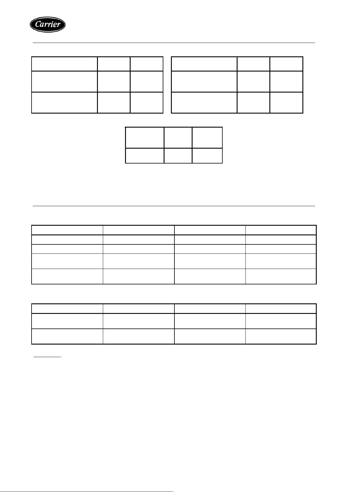
5. SYSTEM OPERATING LIMITS
COOLING HEATING
Difference
Indoor temperature
Maximum
Minimum
Outdoor temperature
Maximum
Minimum
* When the system is operated above or below these limits for a long time, system diagnostics may detect a malfunction
and the unit will not operate properly.
Dry Bulb
Temp. C°
32
21
55
21
Wet Bulb
Temp. C°
23
15
-
-
MAIN POWER SUPPLY
Nominal
Power Supply
V/1PH/50HZ
200-240 180 264
Difference
Indoor temperature
Maximum
Outdoor temperature
Maximum
Minimum
Voltage
Maximum
Voltage
Dry Bulb
Temp. C°
27
21
Wet Bulb
Temp. C°
-
-
6. SYSTEM SAFETY PROTECTION
6-1 FOR HEAT PUMP SYSTEM
PROTECTION TYPE PROTECTION EFFECT OPERATION MODE WHEN ON
Cold draft prevention Indoor fan off Heating mode During unit operation
Defrost cycle Indoor fan off Heating mode During unit operation
Indoor coil
Freeze protection
Against frequent
Compressor cycling
6-2 FOR COOL ONLY SYSTEM
PROTECTION TYPE PROTECTION EFFECT OPERATION MODE WHEN ON
Indoor coil
Freeze protection
Against frequent
Compressor cycling
WARNING:
During heat pump operation the system will undergo several defrost cycles to remove ice that might
collect on the outdoor unit in very low ambient temperature. In these cycles, the indoor fan will be
automatically off and cannot operate until defrost cycle is completed.
Compressor off Cooling mode During unit operation
Compressor
Time delay
Cooling or heating
modes
At unit start-up or change
of operating mode
Compressor off Cooling mode During unit operation
Compressor
Time delay
Cooling mode
At unit start-up or change
of operating mode
5
Page 7

7. EXPLODED VIEW OF INDOOR UNIT
12/1
2
3/9
7
7
12/2
3/8
3/7
12/4
12/3
Pour 42KLE39
3/5
3/6
&
3/4
12/5
12
3/3
9
1
1/6
11 10
3/1
3/2
5/6
4
5/1
6
5/3 5/4
8
5/2
5/5
6
Page 8
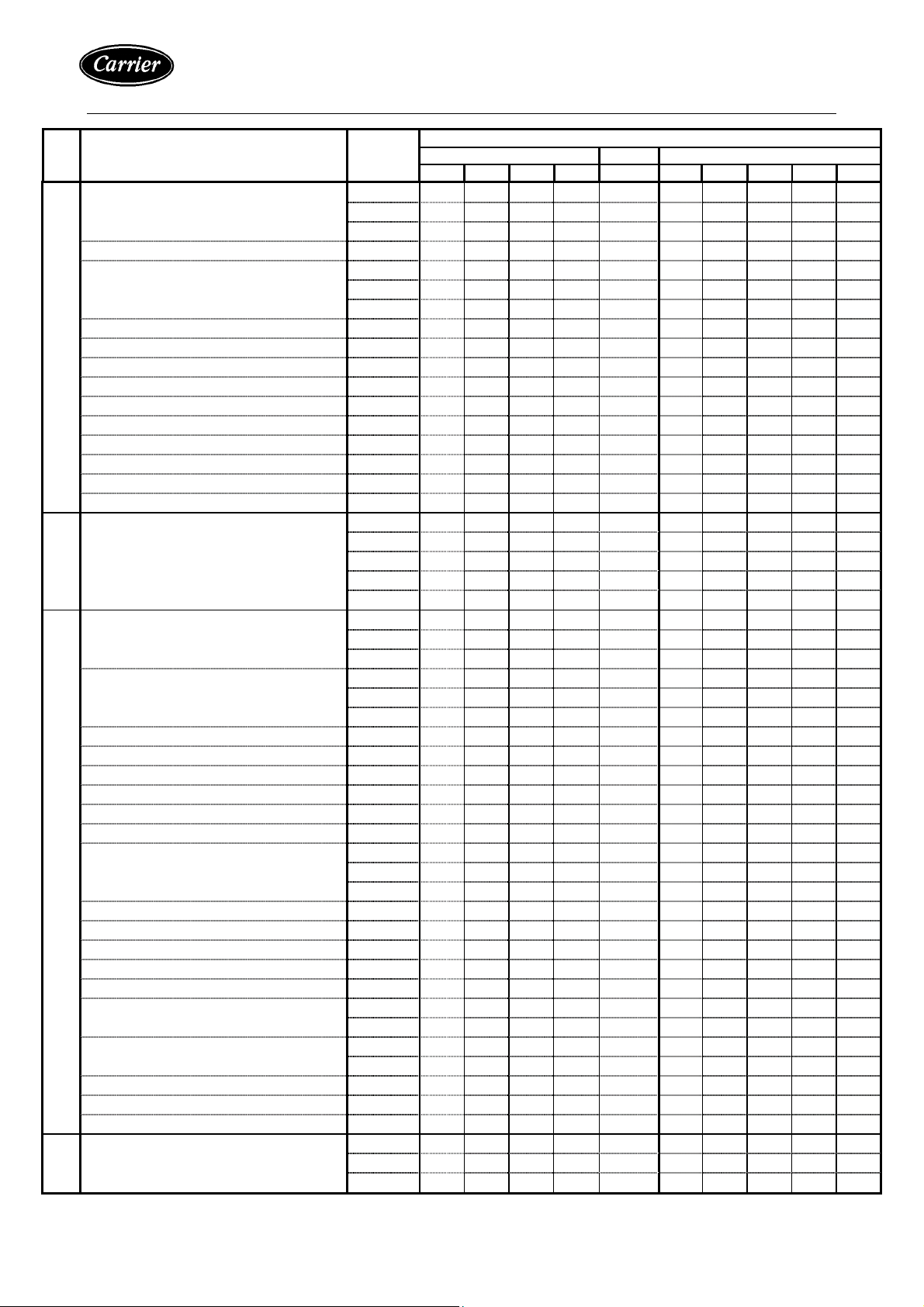
8. PART LIST OF INDOOR UNIT
SR. DESCRIPTION
1 Chassis Subassy 363-13331 1 1 1 1
363-13332 1 1 1 1
363-13333 1 1
1.1 Chassis Side LH Subassy 363-13327 1 1 1 1 1 1 1 1 1 1
1.2 Chassis Back 063-01800 1 1 1 1
063-01801 1 1 1 1
063-01802 1 1
1.3 Fan Deck Support 028-02318 2 2 2 2 2 2 2 2 2 2
1.4 Plug 028-02319 1 1 1 1 1 1 1 1 1 1
1.5 Chassis Side RH Subassy 363-13329 1 1 1 1 1 1 1 1 1 1
1.6 Motor Capacitor
1.6.1 Capacitor 3MFD +/- 5 % , 450 VAC 024-00302 1 1 1 1
1.6.2 Capacitor 5MFD +/- 5 % , 450 VAC 024-00332 1 1 1 1 1 1
1.7 Capacitor Clamp 028-04077 1 1 1 1 1 1 1 1 1 1
1.8 Terminal Block
1.8.1 Terminal Block 6 Poles-30Amps 025-01433 1 1 1 1
1.8.2 Terminal Block 4 Poles-30Amps 025-01413 1 1 1 1 1
2 Evaporator Coil & Headers Subassy 026-00180 1 1
026-00181 1 1
026-00182 1 1
026-00119 1 1
026-00120 1 1
3 Blower Deck Subassy 363-13319 1 1 1 1
363-13320 1 1 1 1
363-13396 1 1
3.1 Blower Deck 063-01807 1 1 1 1
063-01808 1 1 1 1
063-01809 1 1
3.2 Blower
3.2.1 Blower 155 mm Diam x 177.8 mm Width 028-02324 2 2 2 2
3.2.2 Blower 155 mm Diam x 228.6 mm Width 028-02325 2 2 3 2 2 3
3.2.3 Socket Set Screw – Blower 021-00317 2 2 2 2 3 2 2 2 2 3
3.3 Thermistor Clip Nylon 021-00846 1 1 1 1 1 1 1 1 1 1
3.4 Rubber Ring For Housing 028-00685 8 8 8 8 12 8 8 8 8 12
3.5 Motor Support 063-01810 1 1 1 1
063-01625 1 1 1 1
063-07403 1 1
3.6 Motor Clamp Kit C/W Screw & Nut 021-00913 2 2 2 2 2 2 2 2 2 2
3.7 Evaporator Motor
3.7.1 Motor 1/15 HP – 1200/1100/950/800 RPM 024-00096 1 1 1 1
3.7.2 Motor 1/10 HP – 1200/1100/950/800 RPM 024-00097 1 1 1 1
3.7.3 Motor 1/8 HP – 1220/1100/950 RPM 024-00178 1 1
3/8 Blower Housing RH 028-02328 2 2 2 2
028-02329 2 2 3 2 2 3
3.9 Blower Housing LH 028-02326 2 2 2 2
028-02327 2 2 3 2 2 3
3.10 Complement – Motor Shaft 024-00203 1 1
3.11 Coupling Rubber/Metal – Motor 024-00204 1 1
3.12 Bearing & Support Assy – Motor 024-00205 1 1
4 Drain Pan Subassy 363-13334 1 1 1 1
363-13335 1 1 1 1
363-13336 1 1
PART
NUMBER
42KLE-H 42KLE-E 42KLE-C
14 22 28 32 39 14 22 28 32 39
QTY./UNIT
7
Page 9
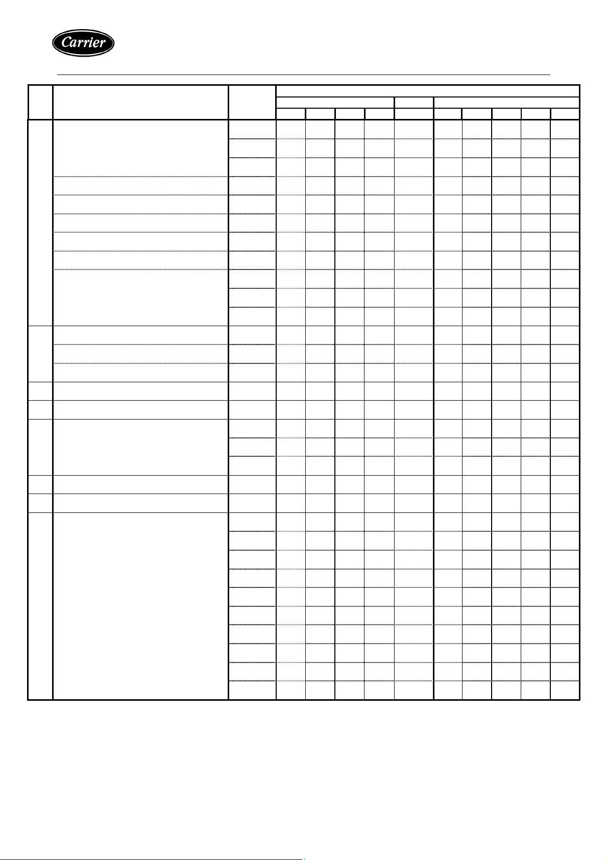
PART LIST OF INDOOR UNIT (Cont.)
SR. DESCRIPTION
PART
NUMBER
42KLE-H 42KLE-E 42KLE-C
14 22 28 32 39 14 22 28 32 39
5 Electrical Box Subassy 363-13338 1 1 1 1 1 1 1 1
363-13364 1 1
5.1 Main PCB 025-03019 1 1 1 1 1 1 1 1 1 1
5.2 Room Sensor 530 ± 30 mm 025-03102 1 1 1 1 1 1 1 1 1 1
5.3 Indoor Coil Sensor 530 ± 30 mm 025-03119 1 1 1 1 1 2 2 2 2 2
5.4 Cable Main PCB – Led PCB 025-01566 1 1 1 1 1 1 1 1 1 1
5.5 Cable Main PCB Step Motor 025-01567 1 1 1 1 1 1 1 1 1 1
5.6 Evap. Electrical Box 028-02334 1 1 1 1 1 1 1 1 1 1
5.7 Set of Cables 025-00883 1 1
025-00884 1 1 1 1
025-00885 1 1 1 1
6 Cabinet Subassy 363-13303 1 1 1 1
QTY./UNIT
(See Details Pages 5 & 6) 363-13304 1 1 1 1
363-13305 1 1
7 Air Filter-Anti Bacteria 028-02303 3 3 4 4 5 3 3 4 4 5
8 Spring for Return Grille 063-01829 1 1 1 1 1 1 1 1 1 1
9 Return Grille Subassy 363-13300 1 1 1 1
363-13301 1 1 1 1
363-13302 1 1
10 Wireless Remote Control 025-03100 1 1 1 1 1 1 1 1 1 1
11 Battery 1.5 Volt Size AAA - Alkaline 025-01125 2 2 2 2 2 2 2 2 2 2
12 Electric Heater Subassy
(Only For 42KLE39-E) 363-19007 1
12.1 Electric Heater Aluminum 4.0 kW 025-00181 1
12.2 Heater Fuse – One Shot 025-01100 1
12.3 Heater Thermostat – Manual Reset 025-01101 1
12.4 Power Relay Heater G7L-2A-T 024-00451 1
12.5 Bracket For Relay 024-00456 1
12.6 Heater Support RH 063-01628 1
12.7 Heater Support LH 063-01627 1
12.8 Heater Support Cover 063-01629 1
8
Page 10

EXPLODE VIEW AND PARTS LISTOF INDOOR UNIT (Cont.)
(A) EXPLODED VIEW
14
3
13
18.1
18.2
1
10
9
8
5
18.3
10
SEE DETAILS
4
6
2
DETAILS
4 & 6
9
Page 11

EXPLODE VIEW AND PARTS LISTOF INDOOR UNIT (Cont.)
(B) PART LIST
SR. DESCRIPTION
PART
NUMBER
42KLE-H 42KLE-E 42KLE-C
14 22 28 32 39 14 22 28 32 39
1 Cabinet Front Subassy 363-13312 1 1 1 1
363-13313 1 1 1 1
363-13314 1 1
2 Cabinet Side RH 028-02305 1 1 1 1 1 1 1 1 1 1
3 Holder Support 028-02321 1 1 1 1 1 1 1 1 1 1
4 Display & Receiver PCB 025-01561 1 1 1 1 1 1 1 1 1 1
5 Cable Main PCB – Led PCB 025-01563 1 1 1 1 1 1 1 1 1 1
6 Receiver Cover 028-02323 1 1 1 1 1 1 1 1 1 1
7 Half Moon Nameplate 029-00108 1 1 1 1 1 1 1 1 1 1
8 Step Motor MP35EAM 024-00167 1 1 1 1 1 1 1 1 1 1
QTY./UNIT
9 Motor Support 028-02314 1 1 1 1 1 1 1 1 1 1
10 Gear 028-02315 1 1 1 1 1 1 1 1 1 1
11 Spacer For Step Motor 063-01839 1 1 1 1 1 1 1 1 1 1
12 Support RH – Flap 028-02311 1 1 1 1 1 1 1 1 1 1
13 Carrier Logo 035-00092 1 1 1 1 1 1 1 1 1 1
14 Cabinet Side LH 028-02304 1 1 1 1 1 1 1 1 1 1
15 Holder Support 028-02321 1 1 1 1 1 1 1 1 1 1
16 Support LH – Flap 028-02309 1 1 1 1 1 1 1 1 1 1
17 Bearing LH – Flap 028-02316 1 1 1 1 1 1 1 1 1 1
18 Flap Subassy 363-11309 1 1 1 1
363-11310 1 1 1 1
363-11311 1 1
18.1 Flap 028-02306 1 1 1 1
028-02307 1 1 1 1
028-02308 1 1
18.2 Blade 028-02312 12 12 16 16 20 12 12 16 16 20
18.3 Blade Bar 028-02313 3 3 4 4 5 3 3 4 4 5
10
Page 12

9. EXPLODED VIEW OF OUTDOOR UNIT
17
1
19/2
4
19/1
19/3
20
2
3
19/5
19/4
15
19/8
19/3
20
21
5
18
16
6
12
8
9
10
13
7
11
14
11
Page 13

10. PART LIST OF OUTDOOR UNIT
SR. DESCRIPTION
PART
NUMBER
38KLE-H 38KLE-C
14 22 28 32 14 22 28 32 39
1 COMPRESSOR C/W GROMMETS & SPACERS
1.1 Mitsushita Comp. 2KS206DSBB04 01500235 1 1
1.2 Mitsushita Comp. 2JS324D3AB07 01500240 1 1
1.3 Mitsushita Comp. 2JS438D3FE02 01500241 1 1
1.4 Copeland Comp. CR37KQ-PFT 01500256 1 1
1.5 Copeland Comp. CR47KQ-PFZ 01500172 1
2 COND. BASE 08107402 1 1 1 1 1 1 1 1 1
3 SUPPORTING LEG ASSY 36314043 4 4 4 4 4 4 4 4 4
4 COND. PARTITION 06307407 1 1 1 1 1 1 1 1
06307436 1
5 CONDENSER COIL SUBASSY.
5.1 Cond. Coil 1 Row – 33.46” x 22” - 12FPI 02600227 1 1
5.2 Cond. Coil 1 Row – 33.46” x 22” - 15FPI 02600228 1 1
5.3 Cond. Coil 2 Row – 33.15” x 22” - 14FPI 02600229 1 1
5.4 Cond. Coil 2 Row – 33.15” x 22” - 15FPI 02600234 1 1
5.5 Cond. Coil 2 Row – 33.15” x 28” - 15FPI 02600231 1
6 CONDENSER MOTOR SUPPORT SUBASSY. 36318880 1 1 1 1 1 1 1 1 1
7 CONDENSER MOTOR
7.1 Motor 1/10 HP-880 RPM 02400154 1 1 1 1 1 1 1 1
7.2 Motor 1/5 HP-860 RPM 02400179 1
8 PROPELLER C/W SOCKET SCREW 8X8MM 02600441 1 1 1 1 1 1 1 1 1
9 ORIFICE PROPELLER 02803112 1 1 1 1 1 1 1 1 1
10 COND. SHROUD 08107406 1 1 1 1 1 1 1 1
06307435 1
21 CARRIER LOGO 02900615 1 1 1 1 1 1 1 1 1
12 HANDLE 02803110 1 1 1 1 1 1 1 1 1
13 GUARD PROPELLER 02803113 1 1 1 1 1 1 1 1 1
14 COND. BACK PANEL 06307409 1 1 1 1 1 1 1 1
06307434 1
15 COUPLING PANEL 06307410 1 1 1 1 1 1 1 1 1
16 SERVICE DOOR 02803106 1 1 1 1 1 1 1 1 1
17 COIL GUARD 02803114 1 1 1 1 1 1 1 1
02803115 1
18 COND. COVER 08107400 1 1 1 1 1 1 1 1 1
QTY./UNIT
12
Page 14

PART LIST OF OUTDOOR UNIT (Cont.)
QTY./UNIT
SR. DESCRIPTION PART NUMBER
14 22 28 32 14 22 28 32 39
19 ELECTRICAL BOX SUBASSY 36314064 1
36314019 1
36314020 1
36314045 1
36313908 1
36313904 1
36314021 1
36314022 1
36313907 1
19.1 DUAL CAPACITOR
19.1.1 Dual Capacitor 35 + 5 MFD/370 VAC 02400376 1 1
19.1.2 Dual Capacitor 45 + 5 MFD/370 VAC * 02400644 1 1
19.1.3 Dual Capacitor 50 + 5 MFD/440 VAC 02400379 1 1 1 1
19.1.4 Dual Capacitor 60 + 5 MFD/440 VAC 02400377 1
19.2 CONTACTOR FOR COMPRESSOR
19.2.1 Contactor 2 poles – 25 Amps 02400580 1 1 1 1 1 1 1 1
19.2.2 Contactor 2 poles – 30 Amps 02400572 1
19.3 TERMINAL BLOCKS
19.3.1 Terminal Block 6 Poles-30 Amps 02501433 1 1 1 1
19.3.2 Terminal Block 4 Poles-30 Amps 02501405 1 1 1 1 1
19.3.3 Terminal Block 3 Poles-30 Amps 02501315 1 1 1 1 1 1 1 1 1
19.4 COND. ELECTRICAL BOX 06307405 1 1 1 1 1 1 1 1 1
19.5 CAPACITOR CLAMP 06301283 1 1 1 1 1 1 1 1 1
19.6 SUPPORT - CABLES 02802523 1 1 1 1 1 1 1 1 1
19.7 ELECTRICAL WIRE HARNESS 02500886 1 1
02500887 1 1 1 1
02500888 1 1
02500873 1
19.8 STARTER FOR COMPRESSOR
19.8.1 PTC Starter Model SPP POW-R-PAK * 02501579 1 1
19.8.2 PTC Starter Model SPP5 02501578 1
20 REVERSING VALVE & ELECTRIC COIL
02200405 1 1 1
02200404 1
21 ACCUMULATOR 02301012 1
22 SENSOR – OUTDOOR COIL 02503121 1 1 1 1
23 TUBING
36319212 1
36319215 1
36319216 1
36319217 1
36319218 1
36319219 1
36319220 1
36319223 1
36319224 1
36319225 1
38KLE-H 38KLE-C
* Option for sizes 14,22 and 28
13
Page 15

11. WIRING DIAGRAM
INDOOR UNIT 42KLE-H SERIES HEAT PUMP
WIRING DIAGRAM
INDOOR UNIT 42KLE-C SERIES COOL ONLY
WIRING DIAGRAM
14
Page 16

WIRING DIAGRAM (CONT.)
INDOOR UNIT 42KLE39-E COOL/ELECTRIC HEAT
WIRING DIAGRAM
15
Page 17

WIRING DIAGRAM (CONT.)
OUTDOOR UNIT 38KLE-H SERIES HEAT PUMP
WIRING DIAGRAM
OUTDOOR UNIT 38KLE-C SERIES COOL ONLY
WIRING DIAGRAM
16
Page 18

12. FIELD ELECTRICAL CONNECTIONS MATCHING
HEAT PUMP SYSTEM COOL ONLY SYSTEM
200-240V ~ 50Hz
200-240V ~ 50Hz
LEGEND
➊ Outdoor Unit
➋ Indoor Unit
➌ Main Switch
➍ Time-delay fuse or circuit breaker
Earth
L Live power supply.
N Neutral power supply.
R Live connection indoor/outdoor unit.
C Neutral connection indoor/outdoor unit.
Y Compressor control.
O Reversing Valve Control (Only for heat pump system).
W2 Outdoor Unit Motor Control (Only for heat pump system).
S1 Outdoor Coil Sensor (Only for heat pump system).
Note: The mains supply must be connected to the outdoor unit.
S2 Outdoor Coil Sensor (Only for heat pump system).
17
Page 19

13. REFRIGERATION CYCLE
HEAT PUMP SYSTEM
18
Page 20

REFRIGERATION CYCLE (Cont.)
COOL ONLY SYSTEM
19
Page 21

14. SELF-DIAGNOSTIC FUNCTION
14-1 INTRODUCTION
- Self-diagnostic function is the key for success of air conditioner.
- The printed circuit boards existing inside the indoor unit are equipped with self-diagnostic function to detect
malfunction and automatically stops the operation at the air conditioner.
14-2 EXPLAINATION OF SELF-DIAGNOSTIC FUNCTION
Once a malfunction is detected, the diagnostic control section will force the system mode to OFF for 3
minutes. After the OFF delay, system mode releases and allowed returning to its normal state. The system
will be allowed to restart on its own. The diagnostic control section will allow the system to fail 5
consecutive times before shutting down the system. If the system is performing an active defrost, both the
compressor drive and reversing valve malfunction test will be cancelled and reinitiated after the following
compressor OFF-ON cycle. The Unit on lamp is scanned every half-second and the error codes are
displayed by the flashing frequency of unit on lamp. The error codes are displayed during SHUT-OFF (3
minutes off and after the 5
14-3 SELF-DIAGNOSTIC FUNCTION DESCRIPTION FOR HEAT PUMP SYSTEMS
The self-diagnostic function included in the control system detects malfunctions of the following
components:
(1) Return Air Sensor (4) Compressor Drive
(2) Indoor Coil Sensor (5) Reversing Valve
(3) Outdoor Coil Sensor
(Rank)
14-4 SELF-DIAGNOSTIC FUNCTION DESCRIPTION FOR COOL ONLY SYSTEMS
The self-diagnostic function included in the control system detects malfunctions of the following
components:
(1) Return Air Sensor (3) Compressor Drive
(2) Indoor Coil Sensor
If more than two errors, the highest rank codes are displayed.
If the highest rank error is cleared, the next rank error codes are displayed.
th
retry failure).
N
UUNNIITT OON
R
TTIIMMEER
CCOOMMP
P
PPOOWWEER
R
No.
1 Return Air Sensor Malfunction 2 Fan Only Mode
2 Indoor Coil Sensor Malfunction 3 Fan Only Mode
3 Outdoor Coil Sensor Malfunction 4 Fan Only Mode
4 Compressor Drive Malfunction 5 Fan Only Mode
5 Reversing Valve Malfunction 6 Fan Only Mode
No.
(Rank)
1 Return Air Sensor Malfunction 2 Fan Only Mode
2 Indoor Coil Sensor Malfunction 3 Fan Only Mode
3 Compressor Drive Malfunction 5 Fan Only Mode
Error
Contents
Error
Contents
Flashing
Frequency
Flashing
Frequency
Allowed
Modes
Allowed
Modes
NOTE
20
Page 22

15. REPLACING BATTERIES OF REMOTE CONTROL
(a) Mount Batteries
Remove the cover of battery compartment at the
bottom back of the remote control by sliding it out in
the direction of the arrow.
(b) Close the cover of the battery compartment
Mount the two-battery size AAA 1.5 Volt supplied with
the remote control.
Note:
During mounting of batteries check battery
symbols (+, -) indicated in batteries
compartment.
(c) Press the RESET button of the wireless remote control
with an object not sharp to operate the remote control.
16. EMERGENCY OPERATION OF AIR-CONDITIONER
EMERGENCY button:
Can be used when the remote control is lost or in operative
N : Position for using the unit via remote control.
C : Emergency position for cooling operation.
H : Emergency position for heating operation.
21
Page 23

17. AIR FILTER CLEANING
- The air filters supplied with the unit are high-efficiency washable and recyclable filters.
- To establish, how frequently these should be cleaned, the operating conditions must be taken in to account.
- REMOVAL OF AIR FILTERS FOR CLEANING:
Open the return grille without removing the two screws and the central
clamp from their position.
Remove acrylic-fiber filters, carbon filter and photocatalytic filter for
cleaning.
- CLEANING OF ACRYLIC-FIBRE STANDARD FILTERS:
First clean the filter with a vacuum cleaner every month. Rinse filter under running water, and dry it
Notes: (1) After cleaning, put the filters back in the correct positions.
(2) Before operating the air conditioner, check that air filters are in their places inside unit.
22
Page 24

18. PERIODICAL CHECKS
For a good operation of the air conditioner it is recommended to carry out checks and maintenance as
indicated.
Recommended maintenance intervals may very depending on the installation environment, e.g. dusty zones,
etc.
Indoor Unit Every Month Every 4 Months Every Year
Clean air filter
Clean drain pipe (2) ●
Change controller batteries ●
Outdoor Unit Every Month Every 4 Months Every Year
Clean outdoor coil from outside (2) ●
Clean outdoor coil from inside ●
Blow air over electric parts (2) ●
Check electric connection tightening (2) ●
Clean fan wheel (2) ●
Check fan tightening (2) ●
Clean drain pan (2) ●
(1) Increase frequency in dusty zones.
(2) Operations to be carried out by qualified service personnel.
●
(1)
23
Page 25

19. TROUBLE SHOOTING
TROUBLE REASON ACTION
Compressor and outdoor fan will not
start
Compressor will not start, but outdoor
fan runs
Compressor runs bur cycles on
internal overload (other than normally
satisfying thermostat)
Compressor operates continuously System undersized for load
Excessive head pressure Dirty outdoor coil
Power failure
Fuse blown or / and circuit breaker tripped
Detective contactor
Low line voltage
Incorrect or loose wiring
Temp. setting too low
Faulty wiring or loose connections in
compressor circuit
Compressor motor burned out, stuck or
internal over-load open
Detective run capacitor
Refrigerant over or under charge
Air or non condensable refrigerant in
system
Detective compressor
Low or too high line voltage
Blocked outdoor coil
Outdoor fan stopped
Detective run capacitor
Faulty fan motor of outdoor section
Restriction in refrigerant system
Capillary or Accurate restricted or ice
clogged.
Temp. setting too low
Defective outdoor fan
Air or non condensable refrigerant in
system
Air restricted or indoor section filter dirty
Detective outdoor fan
Refrigerant over charged
Air or non condensable refrigerant in
system
Outdoor section air restricted
Call power company
Replace fuse or reset circuit breaker
Replace
Determine cause and eliminate
Check wiring diagram and rewire correctly
Reset temp. setting
Check wiring and repair or correct
Replace compressor and determine cause
Replace
Blow refrigerant, evacuate system and
recharge
Blow refrigerant, evacuate system and
recharge
Replace and determine cause
Determine cause and correct
Determine cause and replace
Determine cause and replace
Replace
Replace
Locate restriction and remove
Blow refrigerant, evacuate system and
recharge
Decrease load or increase system size
Reset temp. setting
Check for source and replace
Blow refrigerant, evacuate system and
recharge
Clean filter or remove restriction
Clean coil
Replace
Purge excess refrigerant
Blow refrigerant, evacuate system and
recharge
Remove restricted
24
Page 26

TROUBLE SHOOTING (Cont.)
TROUBLE REASON ACTION
Head pressure too low Low refrigerant charge
Check for leaks, repair and recharge
Restriction in liquid tube
Indoor section air filter dirty
Excessive section pressure Reversing valve hung up or internal leak
Internal pressure relief open
Refrigerant over charged
Suction pressure too low Low refrigerant charge
Indoor unit frosted
Low indoor air or short cycling
Restriction in suction tube
Capillary or accurate restricted or ice clogged
Outdoor fan stopped or cycling on
overload
After batteries have been placed into
Detective fan motor capacitor
Loose leads at fan motor
Fan motor burned out
Motor bearing sized
Batteries are exhausted or have the wrong
Remove restriction
Clear filter
Replace
Check for source and eliminate
Purge excess refrigerant
Check for leaks, repair and recharge
See next trouble
Eliminate cause, check for fan
working
Locate restriction and remove
Blow refrigerant, evacuate system
and recharge
Replace
Check for cause and eliminate
Replace
Check for cause and eliminate
Replace batteries or check polarity.
the remote control, the display is not lit.
When pressing the recessed lock
adjustment button, hour figures on
display do not flash.
appear on display.
When pressing start button, unit does
not acknowledge signal with a beep.
polarity.
Recessed button has not been pressed
correctly.
Recessed button for time setting is blocked due
to excessive pressure during use.
Remote control has been irreversibly damaged. Replace with a new one.
Main switch is OFF. Switch it to ON position.
Remote control batteries are exhausted. Replace batteries.
Remote control has not been pointed correctly to
the receiver of indoor unit.
There are obstacles (curtains, walls, etc.)
between the remote control and the indoor unit
Receiver on the indoor unit or the remote control
is under intense sun radiation.
Signal transmission is obstructed by severe
interference from an electromagnetic field.
Press with a round point, avoid
exerting strong pressure
Check and repair. When pressing any button, all symbols
Turn remote control OFF and repeat
the operation in the correct direction.
Repeat the operation after having
removed the obstacles.
Avoid direct sun on the unit, shut
curtains or shades.
Avoid sending signals when
computers or household appliances
25
(Food processors, coffee makers,
etc.) are operating close by cellular
or cordless telephones may also
interfere with the control.
Page 27

TROUBLE CHART (Cont.)
TROUBLE REASON ACTION
When pressing stop button, unit does
Remote control batteries are exhausted. Replace batteries.
not acknowledge signal with a beep.
When pressing any function button,
the remote control shows the function
requested on the display, but unit
does not acknowledge signal receipt
with a beep and does not carry out the
function.
Remote control has not been pointed
correctly to the receiver of indoor unit.
There are obstacles (curtains, walls, etc.)
between the remote control and the
indoor unit
Receiver on the indoor unit or the remote
control is under intense sun radiation.
Signal transmission is obstructed by
severe interference from an
electromagnetic field.
Main switch is OFF. Switch it to ON position.
Remote control batteries are exhausted. Replace batteries.
Remote control has not been pointed
correctly to the receiver of indoor unit.
There are obstacles (curtains, walls, etc.)
between the remote control and the
Turn remote control OFF and repeat the
operation in the correct direction.
Repeat the operation after having
removed the obstacles.
Avoid direct sun on the unit, shut curtains
or shades.
Avoid sending signals when computers or
household appliances (Food processors,
coffee makers, etc.) are operating close
by cellular or cordless telephones may
also interfere with the control.
Turn remote control OFF and repeat the
operation in the correct direction.
Repeat the operation after having
removed the obstacles.
When pressing any button, display will
not change
Air conditioner will not start.
indoor unit
Receiver on the indoor unit or the remote
control is under intense sum radiation.
Signal transmission is obstructed by
severe interference from an
electromagnetic field.
The triangle symbols 2 ▲is on, as
another signal is being transmitted.
Main supply switch is OFF Switch to ON
Fuses or main switch are blown Replace fuses
Protection against frequent compressor
cycling is ON
Selected temperature is higher than the
room temperature in the cooling mode (or
lower in the heating mode).
Avoid direct sun on the unit, shut curtains
or shades.
Avoid sending signals when computers or
household appliances (Food processors,
coffee makers, etc.) are operating close
by cellular or cordless telephones may
also interfere with the control.
Wait for signal 2 ▲ to disappear and
repeat the operation.
Wait for 3 minutes.
Correct selected temperature.
26
Page 28

TROUBLE CHART (Cont.)
TROUBLE REASON ACTION
Air conditioner is not supplying
enough cooling.
Air conditioner is not supplying
enough heating.
Green LED is flashing System malfunction contact service
Air flow cannot circulate freely Remove obstructions.
Dirty filters reduce air quantity circulating. Clean air filters
Doors and/or windows are open. Close doors and windows
Fan speed has been set to “Low” Set fan speed at high speed.
Air flow direction is not correct Adjust airflow direction as per the mode
Selected temperature is higher than the
room temperature in the cooling mode.
Air flow cannot circulate freely Remove obstructions.
Dirty filters reduce air quantity circulating. Clean air filters
Doors and/or windows are open. Close doors and windows
Fan speed has been set to “Low” Set fan speed at high speed.
Air flow direction is not correct Adjust airflow direction as per the mode
Selected temperature is Lower than the
room temperature in the heating mode.
chosen.
Correct selected temperature.
chosen.
Correct selected temperature.
Refer to the installation manual for fault
A slight mist is emitted from the
indoor unit during cooling
A slight whistling noise is heard when
is heard when the air conditioner
starts or stops.
Water vapor (mist) emanating from the
outdoor unit.
Unpleasant smells coming from the
indoor unit.
center after having made the following
checks:
• Air filters are clean.
• Air circulation is not
obstructed.
• Outdoor unit coil is not
obstructed with a service
reduction of air circulation.
The cool air from the indoor unit is coming
into contact with the room air.
This is due to the refrigerant beginning to
circulate or an adjustment of the
refrigerant pressures.
It is normal in heat pump operation, when
defrost is automatically activated.
Unpleasant smells can be caused by
substances accumulated in the air filters
code reading to be notified to service
center.
Restart air conditioner after having
corrected the faults.
Normal operation
Normal operation
Normal operation
Switch the system OFF and contact an
authorized service center to have the
filters cleaned.
Restart unit in the ventilation (fan only)
mode and open windows to change room
air.
27
Page 29

TROUBLE CHART (Cont.)
TROUBLE REASON ACTION
Strange noises coming from the
indoor unit.
Starting in heating mode for heat
pump systems
Occasionally the indoor unit can emit
some strange short noises during
operation or when it has stopped.
These are generally due to the of
temperature changes on the plastic parts.
If the system starts at low ambient
temperatures, it takes a little while to
reach a comfortable room temperature.
When the system is started by the remote
control, it emits a signal beep, but the
louvre does not swing and the fan does
not run until the operating temperature
has been reached.
Normal operation
Normal operation
28
 Loading...