

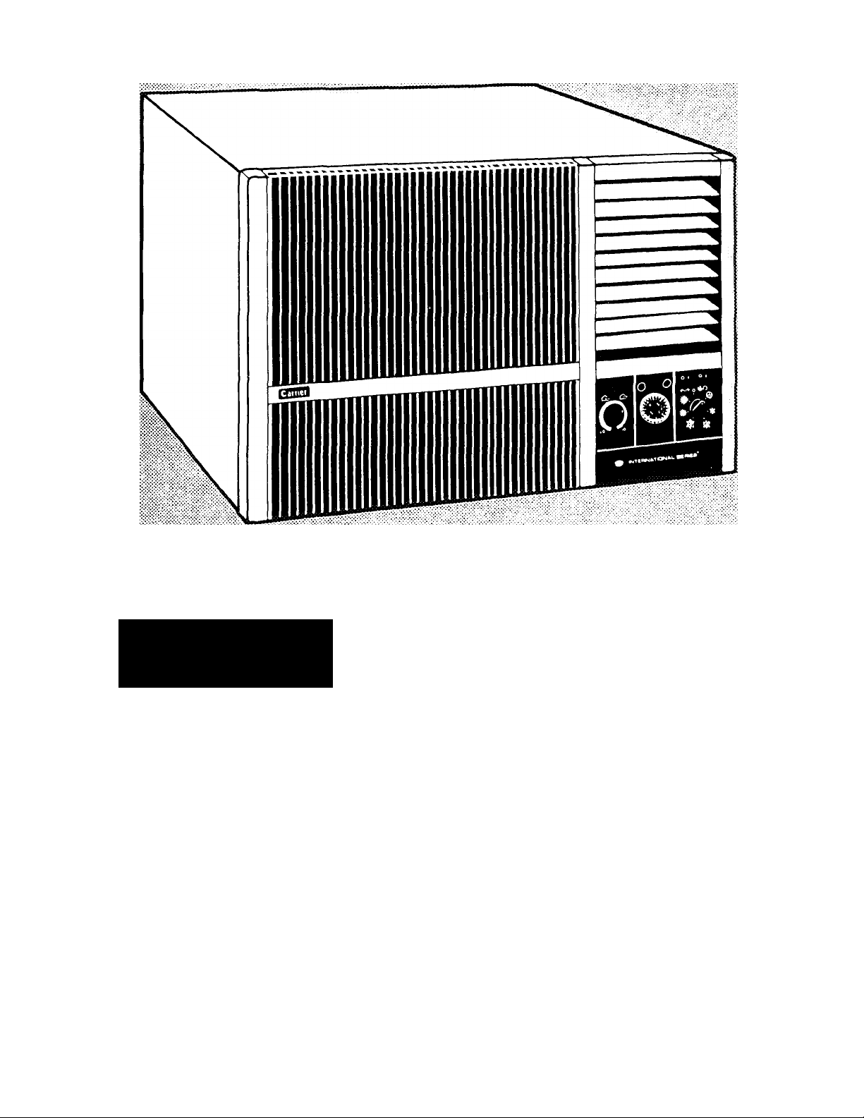
Carrier
Owner’s Guide
INTERNATIONAL SERIES™
Have a question? Need help?
Call 1-800-CARRIER
DEALER’S NAME.
MODEL
51CV/GY
ADDRESS
TELEPHONE.
MODEL NO._
_______
.PURCHASE DATE.
.SERIAL NO..

TABLE OF CONTENTS
Page Nd (
A Few Words About Your New Unit...................................................................................................... 2
Some Suggestions............................................................................................................................... 2
Electrical Data & Specifications............................................................................................................ 3
Glossary of Control Symbols & Operating Instructions........................................................................4
Economic Energy Saving Tips..............................................................................................................6
Tools Needed for Installation................................................................................................................ 7
Through-the-Wall Installation................................................................................................................ 7
Window Installation...............................................................................................................................9
Trouble Shooting Guide......................................................................................................................12
Unit Warranty......................................................................................................................................14

A FEW WORDS ABOUT YOUR NEW CARRIER UNIT...
Thank you for choosing Carrier! You can feel confi-
Jent in your selection because the same pride in
craftsmanship and engineering knowledge that goes
into Carrier equipment at the Astrodome in Texas, the
famous Sistine Chapel in Rome, the United States
Capitol’s Halls of Congress and thousands of other
installations worldwide has gone into the construction
of your unit.
One of the principal advantages of owning a Carrier
room air conditioner with electric heat is that the unit
heats AND cools, so it can be used year-round! While
SOME SUGGESTIONS...
A) To avoid installation difficulties, read instructions
thoroughly before starting. This publication contains
information pertinent to the installation and operation
of the 51 CV/GY Room Air Conditioner with electric
heat.
B) The 51 CV/GY is normally installed through a wall.
During installation, you will remove the unit’s chassis
from the casing, install the casing first and then
re-insert the chassis. CAUTION: COIL FINS ON
‘CHASSIS ARE SHARP AND CHASSIS IS HEAVY.
i
cooling, your new Carrier unit also filters and dehumidifies. In cold weather, the unit gently heats and
circulates air through the room. Carrier’s room air
conditioner with electric heat quietly gives you max
imum year round comfort!
This manual will supply you with all the information
you need for installing, operating and maintaining your
new unit. Take a few moments to read and discover
how to get the most in comfort and economic operation
from your new Carrier room unit!
NOTE: This unit may also be installed in a window. An
additional accessory kit must be ordered separately for
window mounting. Contact your independent Carrier
Dealer, or call 1-800-CARRIER for information.
C) When possible, install unit on a shaded side of the
house or building.
D) Make sure that wall mounting area (or window, if
window-installation is chosen) is structurally sound
enough to support the unit.
BEFORE YOU START
Use the following guide to ensure you have selected
the air conditioning unit that will properly cool the
space you desire This guide is developed for
normal room insulation, number of windows, and
sun exposure, with two people occupying the
conditioned space.
Adjust the room air conditioner capacity found in the
table for the following conditions.
1. Reduce capacity by 10% for heavily shaded
areas.
2 Increase capacity by 10% for very sunny
areas
3 Add 600 Btuh for each additional person
(more than two people)
4. Add 4,000 Btuh if area to be cooled is a
kitchen.
Area To Be Cooled Approximate Nominai
Square Feet
(Length x Width, Ft.)
Cooiing Capacity
Btuh
100-150 5,000
150-250 6,000
250-300 7,000
300-350 8,000
350-400 9,000
400-450 lo'ooo
450-550 12,000
550-700 14,000
700-1,000 18,000
1,000-1,200 21,000
1,200-1,400 23,000
1,400-1,500 24,000
1,500-2,000 30,000
2,000-2,500
34,000
ELECTRICAL DATA...
A) All wiring must comply with local and national elec
trical codes. All wiring must be installed by qualified
and skilled electricians. If you have any questions
regarding the following instructions, contact a qualified
electrician.
B) Check available power supply and resolve any
household wiring problems BEFORE installing and
operating this unit.
C) An individual branch circuit and single wall recepta
cle used only for this appliance, is required. See Table
1 for suggested wire sizes for individual branch circuit.
D) For your safety and protection, this unit is grounded
through the service cord plug when plugged into a
matching wall outlet. If you have any question
whether your wall outlet is grounded or not please
consult a qualified electrician.
E) The wall outlet you select must match the plug on
the unit’s service cord and must be within reach of the
installed unit. Do NOT use adaptors or extension
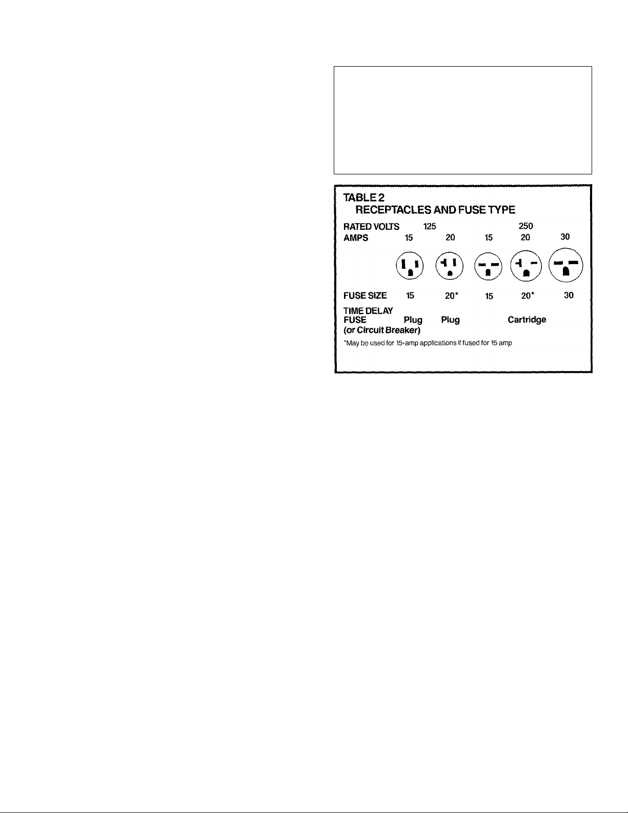
cords. See Table 2 for further receptacle and fuse
information.
F) Follow fuse specifications indicated on unit’s name
plate. See Table 2. Nameplate is located above unit’s
control panel (refer to diagram in Step 7 of Window
Installation Steps). NOTE: Unit’s model and serial
numbers can be found on the nameplate. Record
numbers on the front of this manual for future
reference.
TABLE 1
SUGGESTED INDIVIDUAL BRANCH CIRCUIT
NAMEPLATE AMPS
5.0 to 12
12.1 to 16
16.1 to 24
AWG—American Wire Gauge
'Based on copper wire at 60°C temperature rating
AWG WIRE SIZE*
14
12
10
CAUTIONS:
Manufacturer strongly recommends using two people
during installation of units.
Coil fins on chassis are sharp and chassis is heavy.
Please keep this manual handy for future reference.
Please note: In the summer; condensation (water)
run-off out the unit’s back is normal during cooling
operation under high humidity weather conditions. In
the winter; the unit is designed with a drain located in
the basepan to open at approximately SOT to minimize
formation of ice in the basepan during heating opera
tion. Unit should be installed where condensation
run-off will not drip on pedestrians or neighboring
properties. In addition it may be necessary to re-direct
drainage flow in the winter to prevent possible build-up
of ice on pedestrian walkways. To re-direct drainage
flow, an Accessory External Drain Kit is available.
Contact your independent Carrier Dealer or call
T800-CARRIER for information.
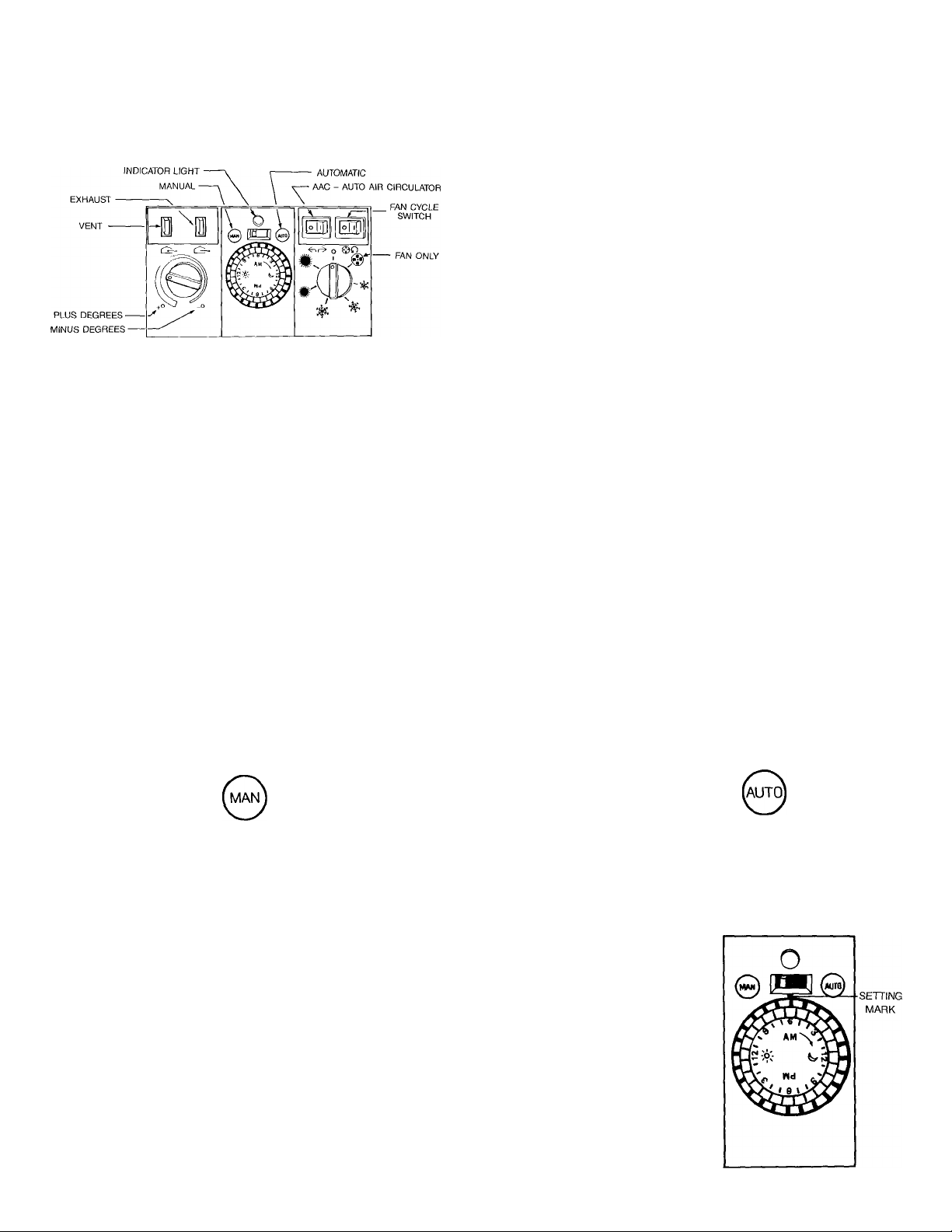
GLOSSARY OF CONTROL SYMBOLS
OPERATING INSTRUCTIONS
\ ■ X
INDtCATOR LIGHT
Amber indicator light is on when unit is in operation.
Indicator light will NOT be on if unit has cycled off due to
a command from the timer control. In such a case, unit
will only be off for the time period set.
OFF O
O symbol on cooling/heating mode control dial is the
pjnit’s OFF position. When dial is turned to this
'' symbol, unitwill NOT operate, in either manual or
automatic setting.
When leaving your home or office for a period of time
during which you do not wish the unit to cycle on for an
automatic setting, be sure cooling/heating mode dial is
set to OFF position.
If you turn unit off, allow two minutes before turning unit
back on.
^ LOW ^MEDIUM ^ HIGH COOL
Choose the cooling setting you want simply by rotating
dial to appropriate size snowflake symbol.
Use the following as a guide for choosing cooling setting;
Low Cool; Recommended for nighttime use.
Medium Cool: Recommended during mid-morning and
early evening hours when outside temperature is lower.
High Cool: Provides maximum cooling. Recommended
for quick cooling or for extremely hot days. Once room
is cooled, manufacturer suggests switching to a lower
cooling setting.
# LOW HEAT ^ HIGH HEAT
Choose the heat setting you want simply by turning
mode control dial to the appropriate size sun symbol.
Use the following as a guide for choosing heating
setting;
Low Heat; Recommended for mildly chilly days and for
nighttime use.
High Heat: Provides maximum heating. Recommended
for sudden temperature drops and extended heating
needs.
THERMOSTAT +0'
Set dial between -FO (warmer) and -O (cooler) symbols
to obtain desired comfort level. This dial has no effect on
fan speed.
i?)-
MANUAL START
Slide switch above timer to MAN setting to operate unit
manually, turning timer off. Set thermostat and cooling/
heating mode dials to desired settings.
FAN ONLY
Set cooling/heating mode control dial to fan symbol.
This will produce air at the low fan speed WITFIOUT
cooling/heating.
When switching to FAN ONLY, allow two minutes before
switching unit back to cooling.
AUTOMATIC OPERATION
I
Your Carrier unit has a timer that allows pre-setting of on
and off times. Set unit to turn on and cool or heat your
home or office before you arrive. Set unit to automati
cally turn off after you leave.
NOTE; Timer must be reset after power failures or
interruptions.
SET TIMER TO TIME OF DAY
Rotate timer dial clockwise
until current time of day lines up
with the setting mark on flat
surface behind dial.
—Noon
—Midnight

Timer pins are positioned inwards (toward center of
dial) from factory to allow continuous operation.
SETTING THE TIMER FOR AUTOMATIC ON/OFF OPERATION
To set the timer, simply slide a pin outward from the dial’s
center for each hour (approximately) that you wish the
unit to be off.
CXDOLING EXAMPLE; You work days 8-4 and want the
unit off while you are at work, and cooling your room
when you arrive home at 5:00 p.m.
1) Slide the pins beginning at 8;00 a.m. through 3;00
p.m. on the dial, away from the center.
2) Switch the timer to AUTO setting.
Now the unit will automatically turn off at 8:00 a.m. and
start at 4:00 p.m. (an hour before you return home so
that the room where your unit is installed is cool and
refreshing).
You can program the timer similarly for the heating
operation.
NOTE: If timer’s switch is on MAN, timer setting will be
overridden and the unitwill run continuously.
You may adjust the cooling or heating speed
while unit is on AUTO, without changing your
timer’s setting.
The timer can be programmed to turn off and on,
one or more times during 24-hour period.
Vent
Exhaust
AIR EXCHANGE
Your Carrier unit is equipped with vent and exhaust air
exchange systems. Use the following guide when
choosing the appropriate system;
Vent: Draws outside air into the room.
Exhaust: Expels stale, smoky or odor laden air from the
room to the outside.
For either system operation, push appropriate button
and turn cooling/heating mode dial to FAN ONLY
setting.
When air exchange is completed, return to normal
cooling or heating by pushing vent or exhaust button
again and rotating mode dial from FAN ONLY to desired
setting.
NOTE; Vent and exhaust usage is not recommended
during cooling or heating as these operations either vent
outside air into the room, or exhaust cooled or heated
air out,
REMEMBER; Button pushed in opens vent or exhaust
system. Button pushed out closes vent or exhaust
system.
AIR DIRECTION
Your 51 CV/GY unit has an Auto Air Circulator control
feature, allowing vertical air deflectors to move automa
tically from left-to right for better air distribution around
the room. For straight forward air discharge, vertical •
air deflectors may be adjusted manually (with auto air
circulator switch in OFF position). The horizontal air
deflectors are also adjusted manually.
OFF-
o
FAN CYCLE
I — This setting lets fan cycle on and off with compres
sor or electric heater. Fan stops when thermostat
setting is satisfied. This mode is recommended for
maximum comfort during heating operations, to
eliminate circulation of unheated room air by the
unit. When used in cooling, this mode results in
longer off time and wider variations in temperature
and humidity.
O — This setting allows continuous fan function, circu
lating air even when compressor or heater has
cycled off and thermostat setting has been
reached. This mode is recommended for maximum
comfort during cooling operation.
ON-
Important HEAT/COOL Feature:
Drain Valve: Your unit has a thermostatically operated ^
drain valve located in its basepan. Valve remains closed M
in warm weather, channeling condensate to outdoor ^
coil to increase cooling efficiency. In cooler weather
(50°F or lower), valve automatically opens, draining
condensate and preventing possible ice build-up in
basepan. It may be necessary to re-direct drainage flow
in the winter to prevent possible build-up of ice on
pedestrian walkways. To re-direct drainage flow, an
Accessory External Drain Kit is available. Contact your
independent Carrier Dealer or call 1-800-CARRlER
for information.
s
i

ECX)NOMiC ENERGY
fSAVING TIPS
Select thermostat setting that suits your comfort needs
and leave thermostat at that chosen setting.
Keep unit’s filter clean. Normally filter should be cleaned
every 30 days. Filter is very efficient in removing airborne
particles. More frequent cleaning may be necessary
depending on outside and inside air quality. To remove
filter: grasp filter tab at bottom of front grille and pull
down and out. Filter may be vacuumed or washed by
hand in warm water. Dry thoroughly and replace filter
by sliding it upward behind front grille.
Use drapes, curtains, shades, etc. to keep direct
sunlight from heating room.
Do not obstruct front of unit.
Use built-in timer to turn unit on just before you return,
rather than running unit while you are out.
When outdoor temperatures are cool enough, use fan
control in conjunction with vent control to bring cool
outside air into room. This utilizes much less electricity.
REMEMBER: Maximum cooling and heating efficiency
is achieved when vent and exhaust systems are off.
Check to make sure vent and exhaust controls are not
while unit is cooling room. Buttons pushed out close
^the vent and exhaust systems.
Your Carrier unit is designed to be highly efficient in
energy savings. Follow the above recommendations for
even greater efficiency.

THROUGH-THE-WALL
INSTALLATION STEPS
The 51 CV/GY is normally installed through a wall.
During installation, you will remove the unit’s chassis
from the casing, install the casing first and then re-insert
the chassis. To slide out chassis, you must first loosen
the chassis security screw.
CAUTION: COIL FINS ON CHASSIS ARE SHARP AND CHASSIS IS HEAVY.
NOTE: This unit may also be installed in a window. An
additional accessory kit must be ordered separately for
window mounting. Contact your independent Carrier
Dealer, or call 1-800-CARRIER for information, and
refer to page 9 for Window Installation Steps.
Two people recommended for installation.
Use Steps 1 through 8 from Window Installation
instructions (page 9) to prepare chassis and casing
for wall installation.
Standard construction and masonry tools are needed
forthrough-the-wall installation. This will include at least
the following;
Screwdrivers—Both Phillips and regular head types
Power drill (1 /8" dia. drill bit)
Pencil
Measuring Tape
Scissors or a razor-edged knife
Note: If wall thickness obstructs unit’s side vents, make wall
opening wider as shown in Figure A. Allow for condensate
drainage from thermostatic drain valve located in basepan. If
outside wall projects beyond back of unit, use baffles on cas
ing ’s rear corners. See Figure A for minimum dimension
For Masonry Framing: Use lintel to support upper
wall and mounting angles if desired. If mounting
angles are used, you may choose to use a plaster
I Cut opening in wall for insertion of unit’s
casing. Finished wall opening must be at least V4
inch larger than unit’s casing on all sides. See
casing dimensions below.
51 CV - W (24 7/16") X H (15 9/16") x D (27 5/16")
51 GY - W (26") X H (17 9/16") x D (28 1 /16")
NOTES
Through-the- Wail Installation of the air conditioner unit is
possible in wood framing or masonry weJI, using units casing
as a sleeve. Installation should be level as unit has a built-in
pitch for draining condensation.
Good framing construction practices must be used to ensure
a properly installed unit.
'1 To prevent a possible air leakage path, sea! the hole in the
bottom of the casing near the front of the unit.
%

For Wood Framing: Provide a wooden framing
support for fastening casing in wall opening.
I
With a pencil, mark location of screw holes to
be drilled through each side of casing to fasten it in
wall opening. NOTE: If existing holes in casing will
suffice for attachment to framing, additional drilled
holes may not be required. Be sure to seal any
fcunused holes in this area. Make sure unit is level.*2
I Fasten casing in wall opening using masonry
or wood screws, anchors, mounting angles or
expansion shields as needed (depending on type
of construction frame used).
I
Recheck pitch of unit for level installation.*3
I
Using 2 people, lift chassis and re-insert into
casing installed in wall opening. See steps 28
through 32 under Window Installation. Follow same
procedures for Through-the-Wall Installation.
CAUTION: Coil fins on chassis are sharp and
chassis is heavy.
I Finish exterior and interior of wall opening
surrounding installed unit. Grouting, caulking or
flashing may be used for sealing and weather
proofing-exterior. *4
Plug in unit and slide excess cord into cord
storage opening.
If needed, drill 2 or 3 screw holes (spaced as
needed, depending on construction frame used) for
each side of casing.
I Paint or apply silicone on edges of drilled holes
to protect against corrosion.
*2 Front Of unit casing must project at least 'k inch into room
to assure proper fit of grille casing on units front.
*3 When casing is installed, using proper installation steps,
unit is properly pitched towards the outdoors to allow for
condensation run-off. An Accessory External Drain Kit is
available to route excess unit condensaron away from build
ing exterior. If unit is installed where condensate drainage will
drip onto pedestn'ans or neighboring properTes, contact your
independent Carrier Dealer, or call 1-800-CARRIER to order
the External Drain Kit.
*4 Be sure to weatherproof exterior area around the wall-
installed unit, and finish surrounding interior walls.
8

WINDOW INSTALLATION STEPS
TOOLS YOU WILL NEED FOR INSTALLATION
Screwdrivers—Both Phillips and reguiar head types
Power drill (1 /8" dia. drill bit)
Pencil
Measuring Tape
Scissors or a razot^edged knife
NOTE: To install your room air conditioner in a double-
hung window, contact your independent Carrier Dealer
for an Accessory Window Installation Kit.
I Remove air conditioner from box by breaking
away sides of box (cutting box could result in
damage to unit).*1
I
Remove two shipping screws at bottom of
casing’s rear panel.
Remove front grille with filter.
I Remove securing screws and lift grille frame
off chassis and away from casing.
I Loosen chassis security screw, located above
control panel, and slide to unlocked position.*2
I
Place unit on stable surface for remainder
of steps.
NOTES
PRIOR to installation, plug in unit and verify operation. Refer
to operating instructions. Some clicking and gurgling sounds
are normal during unit operation. If you received a damaged
ornon-functioning unit, contact your dealer.
If storm window is present, see Step 10 before starting.
*1 Two people recommended for installation.
I While one person holds back of casing,
second person slides chassis out from casing.
NOTE: Coil fins on chassis are sharp and chassis
is heavy.
I Place casing and chassis aside while prepar
ing window for installation.
I Remove bottom track from Accessory Window
Installation Kit.
*2 Unit has slide-out chassis design witii easy access for serv
ice or maintenance needs. A special locking screw secures
the slide-out chassis to prevent unit from being forced out
through the casing to the house, thus preventing an intruder
from gaining entry from the outside.

Measure center of window on sash and sill.
I^Make a small pencil mark to indicate spot. Raise
sash. Position bottom track on sill lining up with
center mark.*3
I Screw track onto sill using 3 short screws.
I Slide wing panels from unit mounting kit into
kit’s upper guide, with drain holes on bottom of wing
panels facing outward for condensation run-off.
I Slip lower portion of connected wing panels
into bottom track now on sill.
I Stretch wing panels out on both sides to meet
window frame.
Lower window sash onto upper guide.
I With sash firmly down upon upper guide,
make a pencil mark on lowered window sash
through center hole on upper guide.
If storm windows present interference, fasten a
2" wide wood strip to window’s sill. Thickness of
wood strip should equal height of storm window’s
ledge. By inserting wood strip, you will create a level
surface for unit installation.
Make pencil marks through all holes in bottom
track while track is positioned on window sill.
I
Remove track and drill three holes in window
sill at marked spots.
*3 If your window width exceeds our maximum recommen
dation, then your unit will require additional support.
I
Drill hole at mark and insert provided short
screw. DO NOT completely tighten screw.
I
Move accordion fold? aside to reveal holes on
sides of wing panels. Use previous marking tech
nique (Step 11) and drill holes in pencil marked
spots. Secure wing panels in sash tracks by insert
ing long screws in drilled holes and tightening.
I
Remove paper backing from narrow seal strip
in unit accessory mounting kit and fasten strip to top
of casing, aligning with pre-drilled holes in casing.
Fasten top channel to top of casing using 4 screws,
inserted upwards from inside casing.

I
Remove screw inserted through center hole of
upper guide in Step 19. This allows for freedom of
movement in future steps. DO NOT RAISE SASH.*4
I Insert casing (without chassis) into framework
now secured in window. Push casing outward, until
bottom slides up and over bend in lower track and
casing’s top channel rests against upper guide of
wing panel assembly.
i Expand accordion folds to meet sides of
installed casing. Screw accordion side panels to
casing sides through pre-made screw openings
in panels. Be sure to use all 3 screw openings to
prevent air seepage.
I With one person on each side, lift chassis
and slide into casing in window. Slide in chassis all
the way.
Make pencil mark through center hole in bot
tom of casing. Drill hole into window sill at spot.
Screw casing to window sill.
I Align center hole in top channel of casing with
center hole in upper guide and previously drilled
hole in sash. Replace and fasten screw removed in
Step 22. TIGHTEN SECURELY.
Cut foam window seal from unit accessory
mounting kit to fit window width. Insert foam down
between top of raised lower sash and glass panes of
upper sash making sure of a firm fit to provide an air
seal. This also prevents insects from gaining
entrance.
I
With chassis back in casing, slide security
screw to locked position and tighten. Refer to
Step 6.*2
\ Replace grille frame on front of unit and fasten
securing screws removed in Step 5.
Replace grille insert removed in Step 4.
Plug in unit, slide excess cord into cord storage
opening.*5
*4 When casing is installed in window, using proper installa
tion steps, unit is property pitched towards the outdoors to
allow for condensation run-off. An Accessory External Drain
Kit is available to route excess unit condensation away from
building exterior. Contact your independent Carrier Dealer, or
call 1-800-CARRIER to order kit.
'5 Unit is designed with power cord extending from right side
of control panel. If wall sodret is located on leftside, unitcan
be modified for power cord to exit on leftside of unit. Remove
grille (Step 4). Remove grille frame (Step 5). Gently slide off
control panel knobs. Remove screws holding control panel in
place and remove panel. Route power cord over to leftside ,(
along front-bottom edge of unit Use pliers to snap outprescored plastic exitsection In lower left corner of grille frame.
Replace control panel and screws, control knobs, grille frame
and screws, and grille. Make sure power cord fits snugly and
properly exits left corner of frame.

TROUBLE SHOOTING GUIDE
If you have problems with your room air conditioner,
check this convenient guide before contacting your service representative.
POSSIBLE CAUSES SOLUTIONS
UNIT DOES NOT START
• Unit may have come unplugged.
• Fuse may have biown.
• Circuit breaker may have been tripped.
• Unit may have been left on AUTO.
UNIT IS NOT COOLING/HEATING ROOM
• Unit’s air output is blocked.
• Temperature setting not high or low enough.
• Dirty air filter.
• Room very hot or coid when unit is started.
• Exhaust or vent left open.
UNIT MAKING NOISES
WATER DRIPPING OUTSIDE
• Check that unit is securely plugged into wail socket.
• Replace the fuse.*
• Reset circuit breaker. *
• Switch into MANUAL mode.
• Remove any curtains, blinds or furniture that may be
blocking unit’s output.
• Reset unit to a lower or higher temperature setting.
• Remove and clean filter.
• Allow sufficient amount of time for unit to heat or cool
room. Use timer to start cooling early before outside
temperature, cooking heat or gatherings of people
make room hot and uncomfortable.
• Close exhaust or vent.
• Clicking, gurgling and whooshing noises are normal
during operation of the unit.
• Condensation run-off during very hot and humid
weather is normal.* **
’ Units with heat feature a thermostatically operated
drain valve in the basepan. The valve automatically
opens to drain condensate. In the case of unusual
water drippage, check to make sure drain valve is
not blocked.
WATER DRIPPING INSIDE
• Unit not installed level.
• Unit must be installed level for proper run-off of
condensation. Check that installation is level and
make any necessary adjustments.
ICE OR FROST FORMS ON COIL
• Low outside temperature.
• Dirty filter
*/f circuit breaker is tripped repeatediy, or fuse is biown more than once, contact a quaiified eiectrician.
** When casing is instailed using proper installation steps, unit is properly pitched toward the outdoors to allow for condensation run-off. An
Accessory External Drain Kit is available to route excess unit condensation away from building exterior. If unit is installed where condensate
drainage will drip onto pedestrians or neighboring property, contact your independent Carrier Dealer, or call 1 -800-CARRIER to order the
r- X«..— I
• When outdoor temperature is approximately 55°F
or below, frost may form when unit is in cooling mode.
Switch unit to FAN operation until ice or frost melts.
• Remove and clean filter.

HOTES
13
i

Carrier
Room Air Conditioner
Warranty
FULL ONE-YEAR WARRANTY — During the first year after originai date of
purchase, Carrier will, through its authorized independent servicing dealers
or service stations* and free of charge to the end user or subsequent user,
repair or replace any part which is defective in material or workmanship
LIMITED TWO- TO FIVE-YEAR WARRANTY — During the 2nd through 5th
years after date of original purchase. Carrier will, through its authorized
servicing dealers and service stations*, repair or replace any part which is
defective in material or workmanship This warranty includes a fixed labor
allowance for repair or replacement of the defective part, BUT DOES NOT
INCLUDE an allowance for labor or other costs incurred in diagnosing the
defect, pick-up or delivery of the product, or transportation or handling
related to the defective part or replacement part ALL IMPLIED WARRAN
TIES HEREUNDER (INCLUDING THE IMPLIED WARRANTIES OF MER
CHANTABILITY AND FITNESS FOR PURPOSE) ARE LIMITED IN DURA
TION TO THE PERIOD FO WHICH THE EXPRESS WARRANTY IS GIVEN
Some states do not allow limitations on how long an implied warranty lasts,
so the above limitation may not apply to you
LIMITATION OF EXPRESS WARRANTIES - THE EXPRESS WARRAN
TIES MADE IN THIS WARRANTY CERTIFICATE ARE EXCLUSIVE AND
MAY NOT BE ALTERED, ENLARGED, OR CHANGED BY ANY DISTRIBU
TOR, DEALER OR OTHER PERSON WHATSOEVER
All work under the terms of this warranty are to be performed during nor
mal working hours Any replacement part assumes the unused portion of
this warranty The replacement part can be a new or remanufactured part as
provided at Carrier’s sole option
NOTE; Service and maintenance items excluded under this warranty certificate may be covered by a service agreement through the seller at time of purchase
*Authorized independent dealers or service stations are registered with Carrier Corporation through its distributor organization
Form No. 530-018 (Rev. 5/90)
This warranty gives you specific rights, and you may aiso have other rights which vary from state to state
CARRIER WILL NOT BE RESPONSIBLE FOR:
1 Normal maintenance or service, including cleaning of condenser or evap
orator coil, cleaning or replacement of air filter, replacement of blown fuses,
or repair of loose connections or defects in house wiring
2 Use or installation of products other than as outlined in the owner’s manual,
including failure to connect to a grounded power supply of sufficient voltage
3 Damage to finish after purchase
4 Damage or repairs needed as a consequence of faulty installation or
misapplication, abuse, unauthorized alteration, improper servicing or
operation
5 Damage as a result of floods, winds, fires, lightning, accidents, corrosive
atmosphere or other conditions beyond the control of Carrier
6 Any parts not supplied or designated by Carrier
7 Product installed outside the continental USA, Alaska, Hawaii and
Canada
8 Shipping damage or damage as a result of transporting the unit
9 ANY SPECIAL, INDIRECT OR CONSEQUENTIAL PROPERTY OR COM
MERCIAL DAMAGE OF ANY NATURE WHATSOEVER Some states do
not allow the exclusion of incidental or consequential damages, so the
above limitation may not apply to you
IF YOUR AIR CONDITIONER DOES NOT WORK,
FOLLOW THESE STEPS IN ORDER:
1 CHECK THE THINGS YOU CAN DO YOURSELF These include
being sure the air conditioner is plugged in firmly in an appro
priate receptacle, checking the fuse or circuit breaker and insur
ing its replacement or resetting, if necessary, and rereading the
instruction book to insure that all controls are set properly By
doing this you can save money Many unnecessary service calls
result in the serviceman doing what the owner can do for him or
herself
2 CONTACT YOUR DEALER OR THE CARRIER AUTHORIZED
SERVICE CENTER You may find his name on the product, on
your invoice or in your Homeowner’s Packet
Unit Model No.
Date of lnstallation_
Name of Owner
____
3 CONTACT THE NEAREST CARRIER DISTRIBUTOR SERVING
YOUR AREA. (See Telephone Yellow Pages )
4 CONTACT CARRIER IF A SATISFACTORY SOLUTION IS NOT
REACHED IN STEPS 2 AND 3.
Carrier Air Conditioning
Consumer Relations Department
P O Box 4808
Syracuse, New York 1322f
Telephone 1-800-CARRIER (227-7437)
From Canada. 1-315-432-7885
Unit Sériai No.
Installed By
___
Address of Installation.

Carrier
WE AREN’T COMFORTABLE
UNTIL YOU ARE
t
Manufacturer reserves the right to discontinue, or change at any time, specifications or designs without notice and without Incurring obligations
Catalog No 565-153
Printed in US A
Form No 51CV,GY-2SI
Replaces; 51CV,GY-1S1
 Loading...