

Page 1
Number One
AirConditbninq
Maker
Division of
Carrier Corporation
Carrier Parkway • Syracuse NY 13221
Single-Package
Water Source Heat Pumps
SAFETY CONSIDERATIONS
INTRODUCTION
...................................................
INSTALLATION....................................................2-4
Step 1 — Check Equipment and
Jobsite
• UNPACKAGE UNIT
• INSPECT EQUIPMENT
• COMPLETE OR CONSIDER THESE
..................................................................
SYSTEM REQUIREMENTS
Step 2 — Connect Supply Ductwork
Step 3 — Make Piping Connections
• CONNECT WATER SUPPLY AND
RETURN LINES
• INSTALL BALANCING VALVES
• INSTALL WATER REGULATING
VALVES
..............................
.................
..................
Page
1
2
2
2
3
INDEX
' ; '*• : '^•s\- >:■ .vt •:■ ; ': <?!v:'! ••• ■ ' .*!^ '; *r\ *i ^*;'!';'i’;*
• MAKE CONDENSATE DRAIN LINE
CONNECTION
Step 4 — Make Electrical Connections.. 3,4
• INSTALL A BRANCH CIRCUIT
DISCONNECT PER NEC
• BRING POWER LEADS INTO UNIT
• CONNECT GROUND LEAD TO
GROUND LUG IN SPLICE BOX
• SET FAN MOTOR SPEED
• CONNECT CONTROL POWER WIRING
START-UP
............................................................
SERVICE...............................................................6
MAINTENANCE
..................................................
Page
4
10
SAFETY CONSIDERATIONS
Installation and servicing of air conditioning
equipment can be hazardous due to system pressure
and electrical components. Only trained and quali
fied service personnel should install, repair or
service air conditioning equipment.
Untrained personnel can perform basic mainten
ance functions of cleaning coils and cleaning and
replacing filters. All other operations should be
performed by trained service personnel. When
working on air conditioning equipment, observe
precautions in the literature, tags and labels
attached to the unit and other safety precautions
that may apply.
Follow all safety codes. Wear safety glasses and
work gloves. Use quenching cloth for brazing
operations. Have fire extinguishers available for all
brazing operations.
WARNING; Before performing service or
mabiienaace operations oa system, turn off
rsi^ swsidr io sodoor anti and oatdoor
onit, Tam acces&oiy Sweater power switch if
applicate. shock, conld cause per-
I'duct conn
FLANGE
© Carrier Corporation 1980
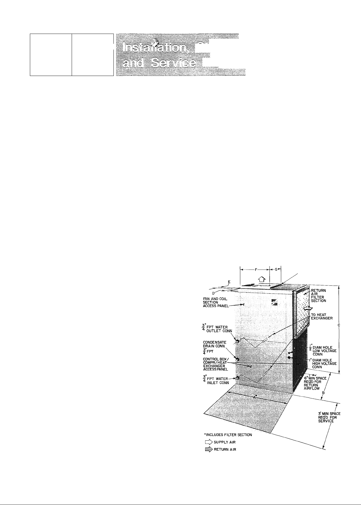
Fig. 1 — Dimensions and Connections
Form 50WQ-2SI
Page 2

' " Table 1
MODEL 50WQ
OPER WT (lb)
DIMENSIONS (ft-in.)
B 1-9-1/8
C
E
SUPPLY DUCT CONN.
(ft-in.) F
G
FILfER (1) Disposable. 1 -in thick
Size (in.)
1 014
220
A
2-10-5/16
D
0- 1-1/2
0- 1-5/8
0-11-1/4
0-10-1/4 0-10-1/4
16x20
— Installation Data (s®e Fi^- 1)
018
240
2-10-5/16 2-10-5/16 3- 2-5/16 1
0- 1-1/2 0- 1-1/2 0- 1-1/2
0- 1-5/8
0-11-1/4 0-11-1/4 0-11-1/4 1
16x20
_
022
260
1-10-1/8 (Includes Filter Section)
0- 7-5/8
0-11-7/8
16x20
027 1 033
,^270 f
1
0- 7-5/8
j
0-11-7/8
1
•
290
3- 2-5/16
0- 1-1/2
0- 7-5/8
0-11-1/4
0-11-7/8
20x20 20x20
3- 2-5/16
042
320
f
0-3
0- 5-7/8
0-10-1/4
1- 1-5/8
INTRODUCTION
The 50WQ units are completely self-contained
cooling and heating systems. They are water-to-air
heat pumps designed for indoor installation. They
may be connected into existing duct systems which
are properly sized and designed to handle air
quantity of 350 to 450 cfm per ton of cooling. Re
quired connections include supply air duct, water
supply and return lines, high- and low-voltage
wiring. Factory-supplied air filter is installed in rack
on unit return air section. See Table I for filter size.
Use recommended thermostat and subbase (Table 3)
for proper unit operation.
INSTALLATION
Step 1 — Check Equipment and Jobsite
UNPACKAGE UNIT — Move to final location.
Slide from carton taking special care not to damage
service valves or grilles.
INSPECT EQUIPMENT — File claim with ship
ping company if shipment is damaged or incomplete.
COMPLETE OR CONSIDER THESE SYSTEM
REQUIREMENTS before installation:
a. Consult local building codes and National Elec
trical Code (NEC) for special installation
requirements.
b. Consider type of water source. Ensure there is an
adequate supply of water at temperature of 45 F
to 90 F with minimum pressure of 10 psig.
c. Provide sufficient space for water piping, con
densate drain, wiring and servicing unit. See
Fig. 1. When front (external) water piping
connections are used, locate unit so piping does
not block front access panels. (Units installed in
confined areas may have to be removed for major
servicing such as compressor or fan motor
replacement.)
d. Provide a minimum 6-in. clearance between
return air filter and adjacent wall.
e. Mount 50WQ on floor or solid platform so unit is
elevated. Make sure unit is supported from the
bottom. To reduce sound transmission, es
pecially when 50WQ is located in a closet or
utility room having louvered doors, the following
acoustical treatment is recommended; place an
isolation pad under unit. Pad must be same size
as unit base. Construct a 1-in. fiberglass sound
shield in front of unit.
Step 2 — Connect Supply Ductwork to unit
supply air duct connection flange. Refer to Fig. 1
and Table 1 for connection size and location. If
necessary, refer to Carrier System Design
Manual, Part 2, for system air duct design. When
designing and installing ductwork, consider the
following:
a. Size duct for 350 to 450 cfm per ton of cooling
capacity.
b. Avoid abrupt duct size increases and reductions.
c. Use flexible connectors between ductwork and
unit to prevent transmission of vibration.
BALANCING VALVES
(2) WITH SHUTOFF
3
MIN
w
i
SUPPLY RETURN
WATER WATER
CONDENSATE TRAP
CONDENSATE DRAIN
Fig. 2 — Water Piping
'WATER
REGULATING
VALVE
► AIRFLOW
i
©
Page 3

Table 2 — Electrical Data (60-Hz)
MODEL
50WQ
■ "014*“
018
022
027
033
""042
" 033"-
042
033
042
FLA — Full Load Amps
LRA — Locked Rotor Amps
RLA — Rated Load Amps
*Permissible limits of the voltage range at which the units will
operate satisfactorily
fRequired when using nonmetallic conduit
V/PH
208-230/1
" -23Ö/T-
208-230/3
460/3
OPER
VOLTAGE*
Max
253
253
253
506
COMPRESSOR ’ FAN
Min
197
187
414
LRA RLA
37 5
54 0 134
65 0
75.0
88 0
100 0
75 0
80 0 18 5 3 2 12 54 10 40
30 0
36 5
_
____
.. 1
FLA Wire Size
60
69
'07”
0.9
1 7
2 5 12
1 1 14
1 6
r -9 6"
133 1 5
16 2
23 3
27 7 32 To 56
13 8' ' '2 5 ■ "'""14
Power
(AWG)
Ï4
14
14
14
.............
152 12 " ■
14
NOTES
1
Fan motors are 208-v, 230-v or 460-v single phase
2
All units equipped with 24-v transformer for external control
circuit
Copper wire sizes based on 60 C Use copper or copper-clad
aluminum wire only.
BRANCH CIRCUIT
Max Ft
Wire
41
33
31
38
43 10
135
118 14 15
Gnd
Wire Sizef
(AWG) Amps
14
14
14 30
12 35
u. ...
14 15
Max
Fuse
20
30
50
6Ö
30
■ **?
Min
Circuit
Amps
”'1"2 7 "■
17.7
18 1
22 0
31 6
-"sT?"'
Ï9 8 ^
26 3
. ^ -
102
Table 3 — Accessories
PART NO.
Fh0Ta"D042'
HH93ÄZÖ44^
38CQ900141
DESCRIPTION UNIT
Honeywell thermostat | Ail
Thermostat Subbase ~j All
Solid-State Time Guard® Device
(Six 38CQ900152)
All
d. Ducts passing thru an unconditioned space must
be insulated and covered with vapor barrier in
accordance with the latest issue of SMACNA
(Sheet Metal and Air Conditioning Contractor’s
National Association) and NESCA (National
Environmental Systems Contractor’s Associa
tion) minimum installation standards for resi
dential heating and air conditioning systems.
Step 3 — Make Piping Connections
CONNECT WATER SUPPLY AND RETURN
LINES to water inlet and outlet pipe connections
shown in Fig. I and 2. Place plug in unused connec
tions. Use flexible hose for water line to reduce
possible vibration and improve unit serviceability.
Make sure hoses or pipes are suitable for system
water pressure and sized for proper flow rate.
CAUTION: Improper heat exchanger water
flow due to pjpiiîg, valving or improper pump
operation is hazardous to units.
For water flow and temperature data refer to
Start-Up section, page 4.
CAUTION: Galvanized pipe or fittings are not
recomtnended for use with these units due to
possible electrolysis.
INSTALL BALANCING VALVES (with shutoff)
in water supply and return lines for water flow
adjustment and a means of water shutoff, if neces
sary, when servicing unit. When multiple units are
conneeted to a eooling tower, valves permit removal
of one unit without interrupting water flow to other
units.
INSTALL WATER REGULATING VALVES (if
used) in water supply line near unit. Multiple unit
installations using cooling tower water do not
normally use a water regulating valve.
MAKE CONDENSATE DRAIN LINE CON
NECTION to female pipe connection provided on
unit. Fig. 2. Install a trap in condensate line as close
as possible to unit. Trap must be at least 3 in. deep
and not higher than the bottom of unit condensate
drain opening. Pitch condensate line to open drain
or sump. Insulate a condensate drain line located
above a living area.
Step 4 — Make Electrical Connections — Field
wiring must comply with local and national fire,
safety and electrical codes. Voltage to unit must be
within the operating voltage range indicated on
nameplate or in Table 2. On 3-phase units, phases
must be balanced within 2%.
Operation of unit on improper line voltage or
with excessive phase imbalance constitutes abuse
and is not covered by Carrier Warranty.
INSTALL A BRANCH CIRCUIT DISCONNECT
PER NEC of adequate size to handle unit starting
current. Locate disconnect within sight of and
readily accessible from the unit, per Section 440-14
of National Electrical Code (NEC).
BRING POWER LEADS INTO UNIT — Extend
leads from diseonnect per NEC thru hole provided
(Fig. 1) into line wiring splice box. Fig. 3.
CONNECT GROUND LEAD TO GROUND
LUG IN SPLICE BOX for safety. Connect power
wiring. See Fig. 3. Splice line power leads to yellow
and black pigtails on single-phase units or yellow
pigtails on 3-phase units. Use wire nuts. Tape each
connection.
Unit transformer on 208-230-volt units is factory
wired for 230/24-volt operation. For 208/24-volt
operation, remove black (230-v) transformer lead
from unit contactor and connect red (208-v) lead to
contactor. Cap unused transformer lead.
Page 4

M
1-PHASE
CONN TO
DISCONNECTPER NEC
_____
GROUND
LEAD
—^YEL —
—^BLK —
,__^GROUND
—Hä] LUG
50WQ
HEAT PUMP
CONTROL BOX
I-PHASE
3-PHASE
CONN. TO
DISCONNECTPER NEC
_____
----- _
GROUND
LEAD
—^YEL —
^^YEL-
^^YEL-
,__^GROUND
—CöJlug
50WQ
HEAT PUMP
CONTROL BOX
3-PHASE
Fig. 3 — Line Power Connections
SET FAN MOTOR SPEED — All units are factory
wired for high fan speed operation. Set fan motor
for medium or low speed operation as follows:
1. Remove unit fan section access panel.
2. Locate Molex fan speed selector block on fan
housing, Fig. 5. Selector block receptacle 1 is
high fan speed, receptacle 2 is medium fan speed
and receptacle 3 is low fan speed. Yellow and
black fan motor power leads from control box
are connected to selector block receptacle C and
1. Yellow lead is common, black lead is speedchange lead.
3. Change fan motor speed by removing black lead
from selector block receptacle 1 and plugging it
into receptacle 2 or 3. Receptacle 4 is not used.
CAUTiONt For proper rniit operaiioit, set unit
fast inoitor ;^>eed ibr air tjuantity mtìàa range
&ÌK>wn in Tabie 4,
Set fan motor speed on 460-volt units — Two-speed
fan motor is factory wired for high-speed operation.
(Yellow and black power leads from control box are
connected to the yellow and black fan motor leads.)
Change fan motor to low speed by wiring as follows:
1. Splice the violet and black fan motor leads
together.
2. Splice yellow and black power leads from control
box to yellow and red motor leads. (Yellow-toyellow and black-to-red.)
CONNECT CONTROL POWER WIRING (24-v)
— Power leads are brought thru 1 / 2-in. hole pro
vided in unit. Fig. 1. Extend leads to low-voltage
terminal board located on top of control box. Fig. 5.
Connect leads to terminal board as shown in Fig. 3.
Use room thermostat HH01AD042 and thermo
stat subbase HH93AZ044 for proper unit operation.
Be sure that field-installed jumper wire is connected
between subbase terminals W and Y. Set thermo
stat heat anticipator at 0.45 amp for 1-phase units
and 0.50 amp for 3-phase units.
2. Ensure that water temperature entering unit is
between 45 F minimum and 90 F maximum. For
water temperature below 60 F, insulate supply
line and install a secondary drain pan under the
unit to remove condensate from heat exchanger
and internal plumbing.
CAUTION: Water teniperattJre otttside
specified temperature range may cause
damage to uiijt.
3. Ensure that supply water is clean and air is
purged from system. Air in supply water causes
scaling in heat exchanger. Foreign material in
water and/or excessive velocity of water can
cause damage to tubing.
4. When using a semi-closed system with an “open”
cooling tower, a water treatment system should
be operational with initial water flow.
To Start Unit — Ensure that air filter is in place on
unit filter flanges provided. Do not operate unit
without filter in place. Adjust the thermostat as
follows:
1. Set selector switch at OFF.
2. Turn on main disconnect switch to unit.
3. Set fan switch as desired (ON or AUTO.).
4. Set thermostat dial at desired temperature.
5. Set selector switch at HEAT or COOL.
Check system refrigerant charge. See Refrigerant
Charging on page 6.
-^Unit Single-Phase Compressors that are
equipped with a compressor start thermistor (PTC
device) — When supply voltage is within limits
indicated on nameplate and compressor will not
start, check the thermistor with an ohmmeter.
If the PTC is good, and the compressor does not
start, disconnect the PTC from the starting circuit
and give unit a temporary capacitance boost. Refer
to Carrier Standard Service Techniques Manual,
Chapter 2, for details on capacitance boost pro
cedure. If unit does not start with capacitance boost,
compressor may be defective. If unit does not start,
check starting capability with PTC assistance. If
questionable, remove PTC, add start capacitor and
start relay per start kit installation instructions.
WARNINGc Caftaciiaace boosa or ijistaliatioa
of start capadtor and start shtutki be per^
fonued by irauted persoaaet improper procedrn» couici cause tajtjry or equipoaeat
damage.
START-UP
Water Flow and Temperature Data
1. Consider design water flow rates for efficient
operation. See Table 4 for permissible water flow
range.
Unit Controls and Safety Devices
HIGH-PRESSURE RELIEF VALVE (except
50WQ0I4) is located in compressor. Relief valve
opens at a pressure differential of approximately
550 psi between suetion (low side) and discharge
(high side) to allow pressure equalization.
Page 5

#
CURRENT AND TEMPERATURE SENSITIVE
OVERLOAD (linebreak) internal on all com
pressors except on 50WQ014 which has external
shell mounted overload. Overload resets auto
matically when internal compressor motor tempera
ture drops to a safe level (overloads may require up
to 45 minutes to reset). When an internal overload
is suspected of being open, check by using an ohmmeter or continuity tester. If necessary, refer to
Carrier Standard Service Techniques Manual,
Chapter 2, for complete instructions.
HIGH-PRESSURE SWITCH opens and shuts
compressor off if discharge pressure rises above
395 psig. Switch closes at 295 psig.
FREEZE-UP PROTECTION — Two controls are
used to prevent unit from operating if water
approaches freezing temperature during heating
cycle.
► 1. Low Water Temperature Cutout (LWTC) —
shuts unit off and energizes lockout relay if
water temperature reaches 37 F.
2. Lockout Relay — locks itself in energized posi
tion and prevents unit from starting.
The unit can be restored to heating operation if
the water temperature rises to 42 F, where the
LWTC will reset, and if the thermostat circuit is
interrupted either by lowering the thermostat setting
or by moving system switch to OFF or COOL.
Thermostat may then be readjusted to normal set
point.
->HEAT PUMP CIRCUITS shown in Fig. 4 are
refrigerant and water flow diagrams for heating and
cooling cycles. Schrader service port located be
tween the reversing valve and the heat exchanger
permits field installation of swivel tee (Carrier Part
No. DD44CA051) for connecting water regulating
valves without losing refrigerant charge.
WATER REGULATING VALVES control water
flow to yield optimum performance in both the
heating and cooling modes.
In cooling, the controlling valve is actuated by
head pressure. As the head increases, the valve opens
and allows more water to flow. If the supply water is
very cold, the head pressure will drop, causing the
valve to throttle back.
In heating, the direct-acting valve is closed due to
very low pressure. The other valve is reverse-acting
and opens on a drop in suction pressure. If the water
temperature drops, the suction pressure will also
drop causing the valve to open. This allows more
water to flow, thereby preventing freeze-up. It also
throttles back if the inlet water temperature rises.
#
COOLING CYCLE
Water In/Water Out can be to a ground water or surface water source
Fig. 4 — 50WQ Refrigerant and Water Flow Diagrams
HEATING CYCLE
Page 6

MODEL 50WQ
R-22 CHG (Ib-oz)'*
Refrig control
Diameter (in. Nom)
Width (in. Nom)
Range Cfm
Motor Hp
Motor Rpm (3 speed)
Water Flow Range
(Gpm)
"Factory refrigerant charge
Table 4 — Service Data
014
10
7
400-600 500-700
1/8 1/8
1 5-5
[’'"“oil 1„...
10
7
2-6
SERVICE
... .... J..........
1-10 1
1-14 1
Capillary Tube
Centrifugal10— Direct Drive
7
600-800
1/6
1075 Nominal
Tube-in-Tube; cupro nickel or copper
2-8 1 2.5-9 I 3-10
027 033
2-0
10
7
750-1000
1/6
2-2
10
7
950-1200
1/4
0«
T-1 r
t
11
7
1040-1375
1/3
4-12
Refrigerant Charging — Unit refrigerant system
is factory charged. When recharging is necessary
during heating or cooling season, weigh in total
charge indicated in Table 4. Remove any refrigerant
remaining in system before recharging. If system has
lost complete charge, evacuate system to 500
microns (29.7 in. vacuum) before recharging.
Service port connections are provided on high and
low sides of refrigerant system for evacuation and
charging. (See Fig. 4 for service port location.)
Dial-a-charge charging cylinder is an accurate
device used to recharge systems by weight. These
cylinders are available at refrigeration supply firms.
To check and/or adjust refrigerant charge during
cooling season, use correct cooling cycle charging
chart (Fig. 6, 8, 10, 12, 14, 16) or Carrier Charge-
master® charging device (Carrier Part No.
38GC680004). Charging charts or Chargemaster
may also be used as alternate methods of recharging
system. Charging methods are described below.
To check system operation during heating cycle,
use correct Heating Cycle Operation Check Chart
(Fig. 7, 9, 11, 13, 15, 17). These charts indicate
whether a correct relationship exists between unit
operating pressures and water temperature leaving
heat exchanger. If pressure and water temperature
lines do not intersect on chart, the system refrigerant
charge may not be correct or other system abnor
malities may exist. Do not use Operation Check
Charts to adjust refrigerant charge. Weigh charge
into system.
FAN SPEED SELECTION BLOCK
(MOLE.X PLUG)
J FPT WATER
OUTLET CONN
SUCTION
SCHRADER
FITTING
DISCHARGE
SCHRADER
FITTING
J"FPT WATER
INLET CONN
Fig. 5
CONTROL BOX
24-V
TRANS
Component Location
6
AIRFLOW
COMPRESSOR
HEAT
EXCHANGER
COMPRESSOR HOLD-DOWN
BOLTS (4)
i
Page 7

COOLING CYCLECHARGING CHART
METHOD
L Operate unit a minimum of 10 minutes before
checking charge, and after each charge
adjustment.
2. Measure suction pressure by attaching a gage to
50WQ unit suction service port (Schrader
Fitting).
3. Measure discharge pressure by attaching a gage
to unit discharge service port (Schrader Fitting).
4. Using a sling psychrometer, measure wet-bulb
temperature of air entering unit.
5. Refer to correct Charging Chart. Locate on
curves where unit discharge pressure line and
indoor air wet-bulb temperature line intersect.
6. From intersect point, project horizontally left to
chart suction pressure line. Compare chart
suction pressure to unit suction pressure (step 2).
7. If unit suction pressure is lower than chart pres
sure, add refrigerant to unit until chart pressure
is reached. If unit suction pressure is higher than
chart pressure, remove refrigerant until chart
pressure is reached.
Fig. 7 — 50WQ014 Heating Cycle Operation
Check Chart (R-22)
<t
Fig. 8 — 50WQ018 Cooling Cycle
Charging Chart (R-22)
Fig. 6 — 50WQ014 Cooling Cycle
Charging Chart (R-22)
COMPRESSOR DISCHARGE PRESSURE® SERVICE PORT (PSIG)
Fig. 9 — 50WQ018 Heating Cycle Operation
Check Chart (R-22)
Page 8

Fig. 10 — 50WQ022 Cooling Cycle
Charging Chart (R-22)
COMPRESSOR DISCHARGE PRESSURE @ SERVICE PORT(PSIG)
Fig. 13 — 50WQ027 Heating Cycle Operation
Check Chart (R-22)
Fig. 11 — 50WQ022 Heating Cycle Operation
Check Chart (R-22)
COMPRESSOR DISCHARGE PRESSURE® SERVICE PORT (PSIG)
Fig. 12 — 50WQ027 Cooling Cycle
Charging Chart (R-22)
Fig. 14 — 50WQ033 Cooling Cycle
Charging Chart (R-22)
ll ■
^1
::: ':i
I'i
LVG^NATE
150 200 250 300
COMPRESSOR DISCHARGE PRESSURE@SERVICE PORT (PSIG)
Fig. 15 — 50WQ033 Heating Cycle Operation
Check Chart (R-22)
Page 9

6. Read evaporator temperature at red needle posi
tion on Chargemaster temperature gage and
suction line temperature at black needle position.
#
COMPRESSOR DISCHARGE PRESSURE® SERVICE PORT (PSIG)
Fig. 16 — 50WQ042 Cooling Cycle
Charging Chart (R-22)
CAUTION; i>o not read evaporator tem
perature witfe Chargernaster valve open.
7. Enter 50WQ Chargemaster Charging Chart,
Table 5, at unit leaving water temperature (step 5)
and evaporator temperature (step 6). (Do not use
standard charging chart on cover of Charge-
master device.) Find the suction line temperature
required for correct system charge. If actual
suction line temperature (step 6) is higher than
table value, the system is undercharged. If
suction line temperature is lower than table
value, the system is overcharged.
Example: At leaving water temperature of 93 F
and evaporator temperature of 41 F, the system is
correctly charged at 50 F ( ± 2 F) suction line
temperature.
8. Add charge by slowly opening Chargemaster
valve. If necessary, reduce charge by bleeding at
liquid line Schrader valve. Check outdoor air and
evaporator temperature during procedure. If
they change, refer back to Chargemaster
Charging Chart for new value.
#
Fig. 17 — 50WQ042 Heating Cycle Operation
Check Chart (R-22)
CHARGEMASTER® DEVICE OPERATION —
Operate unit 10 minutes before using device. Ensure
unit indoor fan section access panel is in place for
proper Chargemaster operation.
1. Tape Chargemaster feeler bulb to unit suction
line. Insulate bulb. Ensure suction line is clean
for good contact with bulb.
2. Connect refrigerant drum to Chargemaster inlet
port with drum in position for vapor charging.
3. Connect Chargemaster outlet port (loosely) to
unit suction line Schrader valve.
4. Crack valves on refrigerant drum and Charge-
master device to purge lines from drum to suction
line Schrader valve. After purging lines, close
valve on Chargemaster device only. Tighten
Chargemaster connection at suction line
Schrader valve.
5. Measure unit leaving water temperature.
Correct use of Chargemaster device ensures that
an optimum refrigerant charge is in system when
conditions and system components are normal.
However, the device does not solve or fix system
abnormalities. It indicates correct charge for condi
tion of system. It does not make corrections for dirty
filters, slow fans, or other abnormal conditions.
This charging device ensures that a correct relation
ship exists between leaving water temperature, evap
orator temperature, and suction line temperature on
a specific system.
Table 5 — Chargemaster Charging Chart
UNIT
LEAVING
WATER
TEMP
(F)
" _
75
81 46
87 48
93
99
105
112
117
123
*Saturated evaporator temperature which is the equivalent tem
perature of pressure taken at unit suction service valve.
3o]
46
45*
EVAPORATOR TEMP (F)
33_I ssJm
Suction Line Temperature (F)
49^4751
505453
49 51
46
41
57
55
54
50 52 54 56 62 65
48 50 53 55 57
47
49 51
45 47
46 49 53 55
45 47 52 55
47 50 53 56
44
59
586160
57 63
56
54
53 56 60 63
50
46
50
—
64
56 61
53 55
61
59
57
64
62
61
56
Page 10

Compressor Removal — See Table 6 for com
pressor information and Fig. 5 for component loca
tion. Follow safety codes, and wear safety glasses
and work gloves. Have quenching cloth available
(step 7).
CAUTION: Copper tubing and alaminum fins
are used in 50WQ unit coils. Do not overheat or
place excessive strain on tubing or damage may
result.
1. Shut off power to unit. Failure to do so may
result in electric shock. Remove unit com
pressor section access panels, Fig. 1.
2. Remove refrigerant from unit using refrigerant
removal methods described in Carrier Standard
Service Techniques Manual, Chapter 1.
3. Remove core from suction and discharge line
Schrader valves.
4. Disconnect compressor wiring at compressor
terminal box.
5. Using a tubing cutter, cut suction and discharge
lines at convenient place near compressor for
easy reassembly to new compressor with copper
slip couplings.
CAUTION: Excessive movement of copper
lines at compressor may cause a break
where lines connect to coil.
Table 6 — Compressor Data
MODEL
50WQ_
014 ~
018
022
027
033
0«
033
042
""^033 "
042
V/PH
208-230/1
230/T
208-230/3
460/3
PRODUCTION
COMPRESSOR
AJ5518E
AB5519F
MD2023HB
MD2423HB
MD3423HB
MD4023HB^
MF3423HB
MF4023HB
" MH"3423HB ^
MH4023HB
OIL
RECHARGE (ozj^
24
32
42
42
42
42
42
MAINTENANCE
CAUTION: Before performing recommended
maintenance^ be sure main power switch to unit
is turned off.
Lubrication
COMPRESSOR contains factory oil charge. Re
place oil when lost. See Table 6 for oil recharge. If
necessary, refer to Carrier Standard Service Tech
niques Manual, Chapter 1, pages 1-21, for oil
recharging procedure. Use Carrier PP33-1, Texaco
Capella B or Suniso 3G oil.
6. Remove compressor hold-down bolts and lift
compressor out.
7. Carefully unbraze suction and discharge line
piping stubs from compressor. If oil vapor in
piping stubs ignites, use quenching cloth.
8. Braze piping stubs (removed in step 7) on new
compressor.
9. Clean system. Add new suction line filter-drier
as described below.
10. Install new compressor in unit. Braze suction
and discharge lines to compressor piping stubs
(at points where cut, step 5) using field-supplied
copper couplings. Ensure compressor holddown bolts are in place. Connect wiring.
11. Evacuate and recharge unit.
Filter-Drier — Install a filter-drier in compressor
suction line when refrigerant system is opened for
service as described under Compressor Removal.
Check filter-drier pressure drop at drier service port
and unit suction line Schrader fitting. Ensure
pressure drop does not exceed 2 psi.
FAN MOTOR BEARINGS are prelubricated for 3
years heavy-duty or 5 years normal-duty service.
When lubrication is necessary, send motor to
authorized motor repair shop.
Cleaning Coil and Condensate Pan — Clean and
inspect coil, condensate pan and drain before each
cooling season.
1. Remove coil section access panels and slide air
filter out of filter flanges.
2. Disconnect condensate drain line at pan drain
connection.
3. Use vacuum cleaner nozzle to clean the face of
coil.
4. Clean condensate drain trap with a bottle brush.
Clean condensate pan.
5. Hold pail under condensate pan drain connec
tion and flush pan out with clean water. Ensure
water flows freely thru condensate drain. Do not
overflow pan.
6. Reconnect condensate drain line.
7. Install access panel and air filter.
10
Page 11

Indoor Fan Wheel should»be centered in housing.
To adjust fan, loosen setscrew holding fan to motor
shaft. Adjust fan and retighten setscrew.
INDOOR BLOWER ASSEMBLY REMOVAL
1. Remove fan section access panel, Fig. 1.
2. Remove power wires from Molex plug. Fig. 5.
3. Place a spacer beneath blower housing for
support.
4. Remove blower assembly mounting bracket.
(Rear flange on top of blower housing and spacer
now hold blower assembly in place.)
5. Support blower housing at bottom and remove
spacer. Tilt blower assembly downward and lift
out of unit.
Indoor Fan and Motor Removal
1. Remove blower assembly from unit.
2. Remove Molex plug from bracket on fan
housing.
3. Loosen setscrew holding fan to motor shaft.
4. Loosen motor mounting band and remove
motor.
5. Remove fan cdtoff plate from blower housing
outlet.
6. Remove fan wheel from blower housing outlet.
Clean Indoor Fan Wheel — When coil is cleaned,
remove caked-on dirt from fan wheel and housing
with brush; remove grease with mild solvent. When
replacing blower assembly, make sure fan wheel is
centered in housing.
Return Air Filter — Replace throwaway filter 4
times a year. For other types of filters, refer to filter
manufacturer’s instructions as required.
CAUTION: Never operate unit without a filter
as coil will plug and damage to fan motor may
result.
Heat Exchanger — If excessive discharge pressure
is experienced with normal water flow, the heat
exchanger tubes may be fouled and require cleaning.
Contact a local water treatment firm for details on
chemical cleaning.
11
Page 12

For replacement items use Carrier Specified Parts.
Manufacturer reserves the right to discontinue, or change at any time, specifications or designs without notice and without incurring obligations.
#
Book 1
Tab 5a
4
5a
Form50WQ-2SI Supersedes 50WQ-1 SI Printed in U S.A
12-80
PC101
Catalog No 535-063
 Loading...