

Carrier 50RHE006-060 User Manual
Water Source Heat Pumps
Installation, Start-Up, and
Service Instructions
Aquazone™
50RHE006-060
Horizontal Unit
50 Hz, CE Mark
R-407C
CONTENTS
Page
SAFETY CONSIDERATIONS ...................1,2
GENERAL ........................................2
INSTALLATION ............................. 2-16
Step1—CheckJobsite........................2
Step2—CheckUnit...........................2
• STORAGE
• PROTECTION
• INSPECT UNIT
Step 3 — Unit Location...........................6
• FIELD CONVERSION OF DISCHARGE AIR
Step 4 — Mounting the Unit ......................7
Step 5 — Duct System ...........................7
• SOUND ATTENUATION
• EXISTING DUCT SYSTEM
Step 6 — Condensate Drain ...................... 7
• VENTING
Step 7 — Piping Connections ....................8
• WATER LOOP APPLICATIONS
• GROUND-WATER APPLICATIONS
• GROUND-LOOP APPLICATIONS
Step 8 — Electrical Wiring........................ 9
• POWER CONNECTION
• SUPPLY VOLTAGE
• 220-VOLT OPERATION
• PSC BLOWER SPEED SELECTION
Step 9 — Low Voltage Wiring....................16
• THERMOSTAT CONNECTIONS
• WATER FREEZE PROTECTION
• AIR COIL FREEZE PROTECTION
• ACCESSORY CONNECTIONS
• WATER SOLENOID VALVES
PRE-START-UP ................................16,17
System Checkout .............................16
FIELD SELECTABLE INPUTS ................17,18
C Control Jumper Settings ....................17
C Control DIP Switches .......................17
D Control Jumper Settings ....................17
D Control DIP Switches .......................17
D Control Accessory Relay Configurations .....18
Water Valve (Slow Opening) ...................18
Outdoor Air Damper (OAD) ....................18
START-UP .................................... 18-21
Operating Limits ................................18
Scroll Compressor Rotation.....................19
Unit Start-Up Cooling Mode .....................19
Unit Start-Up Heating Mode ..................... 19
Flow Regulation................................. 19
Flushing ........................................20
Antifreeze .......................................21
Cooling Tower/Boiler Systems .................. 21
Page
Ground Coupled, Closed Loop and Plateframe
Heat Exchanger Well Systems ................21
OPERATION...................................21,22
Power Up Mode .................................21
Units with Aquazone Complete C Control .......21
Units with Aquazone Deluxe D Control.......... 21
SYSTEM TEST ................................22,23
Test Mode....................................... 22
Retry Mode......................................23
Aquazone Deluxe D Control LED Indicators .....23
SERVICE ..................................... 23-25
Filters ........................................... 23
Water Coil ....................................... 23
Condensate Drain Pans ......................... 24
Refrigerant System..............................24
Condensate Drain Cleaning ..................... 24
Air Coil Cleaning ................................ 24
Condenser Cleaning ............................24
Checking System Charge .......................24
Refrigerant Charging............................ 25
Air Coil Fan Motor Removal ..................... 25
TROUBLESHOOTING ........................ 25-27
Thermistor ...................................... 25
Control Sensors................................. 25
START-UP CHECKLIST .................. CL-1,CL-2
IMPORTANT: Read the entire instruction manual before
starting installation.
SAFETY CONSIDERATIONS
Installation and servicing of air-conditioning equipment can
be hazardous due to system pressure and electrical components. Only trained and qualified service personnel should
install, repair, or service air-conditioning equipment.
Untrained personnel can perform basic maintenance functions of cleaning coils and filters and replacing filters. All other
operations should be performed by trained service personnel.
When working on air-conditioning equipment, observe precautions in the literature, tags and labels attached to the unit, and
other safety precautions that may apply.
Improper installation, adjustment, alteration, service, maintenance, or use can cause explosion, fire, electrical shock or
other conditions which may cause personal injury or property
damage. Consult a qualified installer, service agency, or your
distributor or branch for information or assistance. The
qualified installer or agency must use factory-authorized kits or
accessories when modifying this product. Refer to the individual instructions packaged with the kits or accessories when
installing.
Manufacturer reserves the right to discontinue, or change at any time, specifications or designs without notice and without incurring obligations.
Book 1 4
Ta b 5 a 5 a
Catalog No. 005-00042 Printed in U.S.A. Form 50RHE-C1SI Pg 1 2-04 Replaces: New
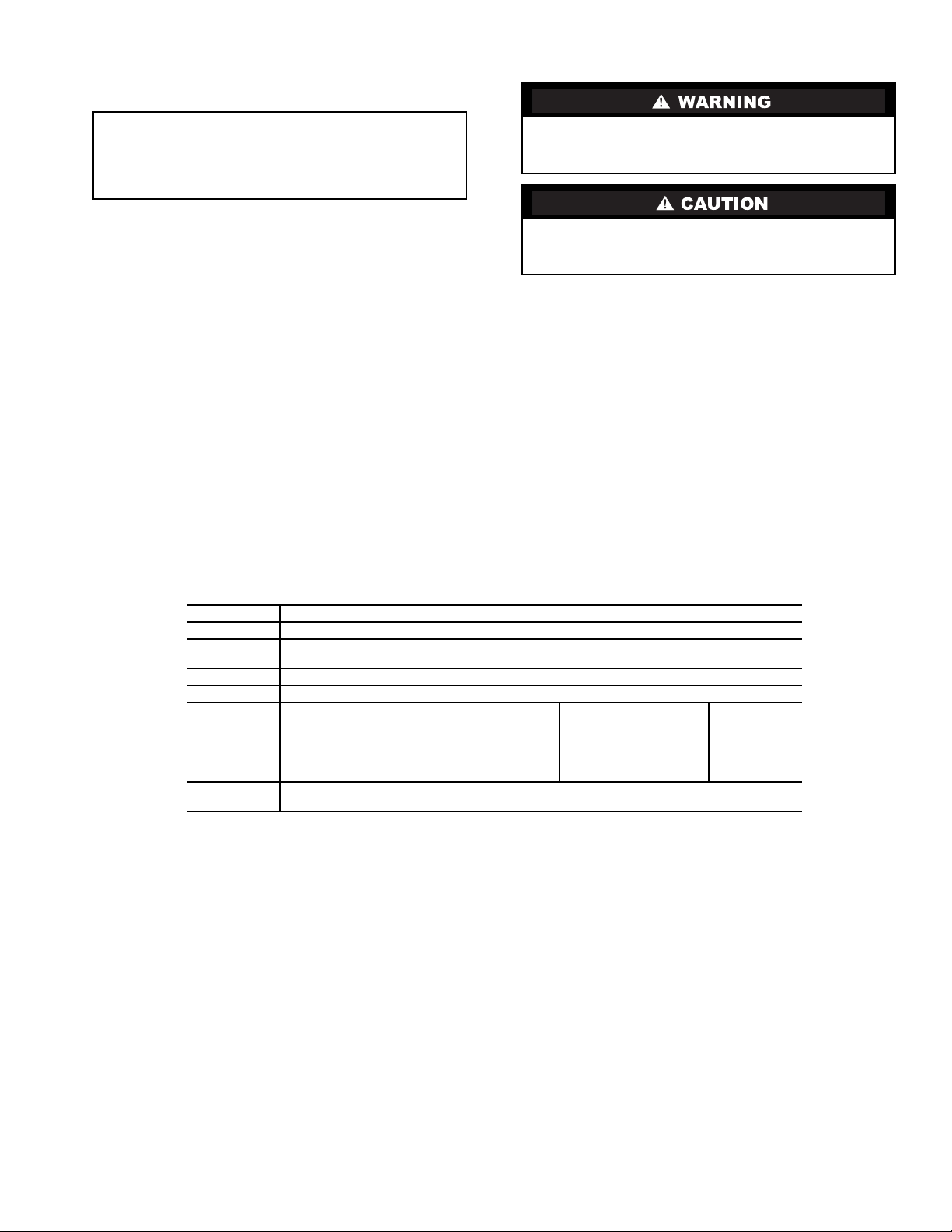
Follow all safety codes. Wear safety glasses and work
gloves. Use quenching cloth for brazing operations. Have fire
extinguisher available. Read these instructions thoroughly and
follow all warnings or cautions attached to the unit. Consult
local building codes and electrical codes for special installation
requirements.
Understand the signal words — DANGER, WARNING,
and CAUTION. DANGER identifies the most serious hazards
which will result in severe personal injury or death. WARNING signifies hazards that could result in personal injury or
death. CAUTION is used to identify unsafe practices, which
would result in minor personal injury or product and property
damage.
Recognize safety information. This is the safety-alert
symbol ( ). When you see this symbol on the unit and in
instructions or manuals, be alert to the potential for personal
injury.
Electrical shock can cause personal injury or death. Before
installing or servicing system, always turn off main power
to system. There may be more than one disconnect switch.
Turn off accessory heater power if applicable.
GENERAL
This Installation and Start-Up Instructions literature is for
Aquazone™ Water Source Heat Pump units bearing the Mark
of The European Community (CE). These units are designed in
accordance with European Standard EN60335-2-400.
Water Source Heat Pump (WSHP) units are single-package
horizontal mounted units with electronic controls designed for
year-round cooling and heating. Aquazone 50RHE WSHP
units are designed for high-efficiency operation using HFC407C refrigerant.
IMPORTANT: The installation of water source heat pump
units and all associated components, parts, and accessories
which make up the installation shall be in accordance with
the regulations of ALL authorities having jurisdiction and
MUST conform to all applicable codes. It is the responsibility of the installing contractor to determine and comply
with ALL applicable codes and regulations.
INSTALLATION
Step 1 — Check Jobsite —
maintenance instructions are provided with each unit. Before
unit start-up, read all manuals and become familiar with the
unit and its operation. Thoroughly check out the system before
operation. Complete the inspections and instructions listed
below to prepare a unit for installation. See Table 1 for unit
physical data.
Horizontal units are designed for indoor installation only.
Be sure to allow adequate space around the unit for servicing.
See Fig. 1 for overall unit dimensions. Refer to Fig. 2 for an
illustration of a typical horizontal installation.
To avoid equipment damage, do not use these units as a
source of heating or cooling during the construction
process. The mechanical components and filters used in
these units quickly become clogged with construction
dirt and debris which may cause system damage.
Installation, operation and
Step 2 — Check Unit — Upon receipt of shipment at
the jobsite, carefully check the shipment against the bill of
lading. Make sure all units have been received. Inspect the carton or crating of each unit, and inspect each unit for damage.
Ensure the shipping company makes proper notation of any
shortages or damage on all copies of the freight bill. Concealed
damage not discovered during unloading must be reported to
the shipping company within 15 days of receipt of shipment.
NOTE: It is the responsibility of the purchaser to file all
necessary claims with the shipping company.
1. Verify unit is correct model for entering water temperature of job.
2. Be sure that the location chosen for unit installation provides ambient temperatures maintained above freezing.
Well water applications are especially susceptible to
freezing.
3. Be sure the installation location is isolated from sleeping
areas, private offices and other acoustically sensitive
spaces.
NOTE: A sound control accessory package may be used
to help eliminate sound in sensitive spaces.
4. Check local codes to be sure a secondary drain pan is not
required under the unit.
5. Be sure unit is mounted at a height sufficient to provide
an adequate slope of the condensate lines. If an appropriate slope cannot be achieved, a field-supplied condensate
pump may be required.
6. Provide sufficient space for duct connection.
7. Provide adequate clearance for filter replacement and
drain pan cleaning. Do not allow piping, conduit, etc. to
block filter access.
8. Provide sufficient access to allow maintenance and
servicing of the fan and fan motor, compressor and coils.
Removal of the entire unit from the closet should not be
necessary.
9. Provide an unobstructed path to the unit within the closet
or mechanical room. Space should be sufficient to allow
removal of unit if necessary.
10. Provide ready access to water valves and fittings, and
screwdriver access to unit side panels, discharge collar,
and all electrical connections.
11. Where access to side panels is limited, pre-removal of the
control box side mounting screws may be necessary for
future servicing.
STORAGE — If the equipment is not needed immediately at
the jobsite, it should be left in its shipping carton and stored in a
clean, dry area of the building or in a warehouse. Units must be
stored in an upright position at all times. If carton stacking is
necessary, stack units a maximum of 3 high. Do not remove
any equipment from its shipping package until it is needed for
installation.
PROTECTION — Once the units are properly positioned on
the jobsite, cover them with either a shipping carton, vinyl film,
or an equivalent protective covering. Cap open ends of pipes
stored on the jobsite. This precaution is especially important in
areas where painting, plastering, or spraying of fireproof material, etc. is not yet complete. Foreign material that accumulates
within the units can prevent proper start-up and necessitate
costly clean-up operations.
Before installing any of the system components, be sure to
examine each pipe, fitting, and valve, and remove any dirt or
foreign material found in or on these components.
2
3. Do not remove the packaging until the unit is ready for
installation.
DO NOT store or install units in corrosive environments or
in locations subject to temperature or humidity extremes
(e.g., attics, garages, rooftops, etc.). Corrosive conditions
and high temperature or humidity can significantly reduce
performance, reliability, and service life. Always move
units in an upright position. Tilting units on their sides may
cause equipment damage.
4. Verify that the refrigerant tubing is free of kinks or dents,
and that it does not touch other unit components.
5. Inspect all electrical connections. Be sure connections are
clean and tight at the terminals.
6. Compressors are internally isolated. Compressors
equipped with external spring vibration isolators must
have bolts loosened and shipping clamps removed.
7. Remove any blower support cardboard from inlet of the
INSPECT UNIT — To prepare the unit for installation, complete the procedures listed below:
1. Compare the electrical data on the unit nameplate with
ordering and shipping information to verify that the
correct unit has been shipped.
blower.
8. Locate and verify any accessory kit located in compressor
section.
9. Remove any access panel screws that may be difficult to
remove once unit is installed.
2. Verify that the unit is the correct model for the entering
water temperature of the job.
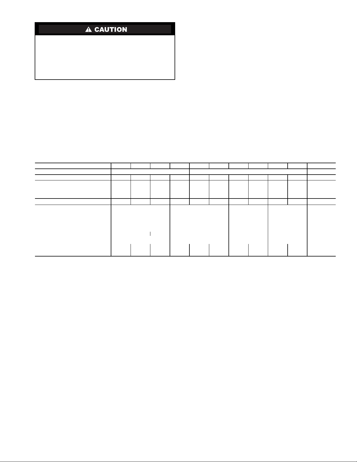
Table 1 — Physical Data — Aquazone™ 50RHE006-060 Units
UNIT 50RHE 006 009 012 015 019 024 030 036 042 048 060
COMPRESSOR (1 each) Rotary Reciprocating Scroll
FACTORY CHARGE R-407C (kg) 0.34 0.37 0.37 0.68 0.88 0.91 1.19 1.36 1.19 1.59 2.41
PSC FAN MOTOR AND BLOWER
Fan Motor Type/Speeds PSC/3 PSC/3 PSC/3 PSC/3 PSC/3 PSC/3 PSC/3 PSC/3 PSC/3 PSC/3 PSC/3
Fan Motor (Hp) [w]
Blower Wheel Size (D x W) (mm) 127 x 127 127 x 127 152 x 127 152 x 127 152 x 127 152 x 127 152 x 127 254 x 254 254 x 254 254 x 254 279 x 254
WATER CONNECTION SIZE (in.) (FPT)
HORIZONTAL
Air Coil
Dimensions (H x W) (mm) 254 x 406 406 x 406 457 x 559 457 x 787 508 x 889
Total Face Area (m
Tube Size (mm) 9.5
Distance Between Fins (mm) 2.2 2.2 2.2 2.2 2.7
Number of Rows 23 3 3 3 4
Filter Standard Throwaway
(Qty — Size, mm)
Weight 25.4-mm (kg)
Operating 50.0 50.9 55.0 66.8 76.8 87.7 99.5 104.1 116.8 121.4 146.8
Packaged 54.5 55.5 59.5 71.4 81.4 92.3 105.0 109.5 122.3 126.8 153.6
PSC — Permanent Split Capacitor
LEGEND
2
) 0.103 0.165 0.255 0.360 0.452
1
/25[30]1/10[75]1/10[75]1/6[124]1/5[150]1/3[250]1/2[373]3/4[560]3/4[560]3/4[560] 1 [746]
1
/
1
2
/
1 — 254 x 508 1 — 406 x 508 1 — 457 x 610 2 — 457 x 457
1
2
/
3
2
/
3
4
/
9.5 9.5 9.5 9.5
NOTES:
1. All units have spring compressor mountings, TXV (thermostatic expan-
2. Size 048 available as high-static unit.
3
4
/
sion valve) expansion devices, and1/2-and3/4-in. electrical knockouts.
3
4
/
3
4
/
4
11 1
1 — 305 x 508
1 — 635 x 508
3
WATER
OVERALL
50RHE
UNITS
in. 22.4 43.1 11.3 2.4 5.4 0.6
006-012
cm 56.8 109.5 28.7 6.1 13.7 1.5 8.9 14.0 20.8 14.7 10.2 14.7 20.3 14.7 3.8 43.4 23.6 5.6 2.5
in. 22.4 43.1 17.3 2.4 4.9 0.6
015-024
cm 56.8 109.5 43.9 6.1 12.4 1.5 8.9 19.1 25.9 12.7 14.2 26.4 23.6 12.7 3.8 43.4 38.9 5.6 2.5
in. 22.4 53.2 19.3 2.4 5.4 0.6
030
cm 56.8 135.1 49.0 6.1 13.7 1.5 14.5 24.6 31.0 12.7 17.3 26.4 23.6 12.7 5.3 58.7 43.9 5.6 2.5
in. 22.4 53.2 19.3 2.4 5.4 0.6
036
cm 56.8 135.1 49.0 6.1 13.7 1.5 14.5 24.6 31.0 7.4 9.7 34.3 33.3 7.4 4.8 58.7 43.9 5.6 2.5
in. 22.4 62.2 19.3 2.4 5.4 0.6
042-048
cm 56.8 158.0 49.0 6.1 13.7 1.5 14.5 24.6 31.0 7.4 9.7 34.3 33.3 7.4 4.8 81.5 43.9 5.6 2.5
in. 25.4 71.2 21.3 2.4 5.4 0.6
060
cm 64.5 180.8 54.1 6.1 13.7 1.5 20.6 29.7 36.1 14.7 12.7 34.5 33.8 14.7 7.4 91.7 49.0 5.6 2.5
NOTES:
1. Condensate is3/4-in. FPT copper.
2. Horizontal unit shipped with filter bracket only. This bracket should be removed for return duct connection (front).
3. Hanger kit is factory installed. Isolation grommets are provided.
4. Right and left orientation is determined by looking at water connection side.
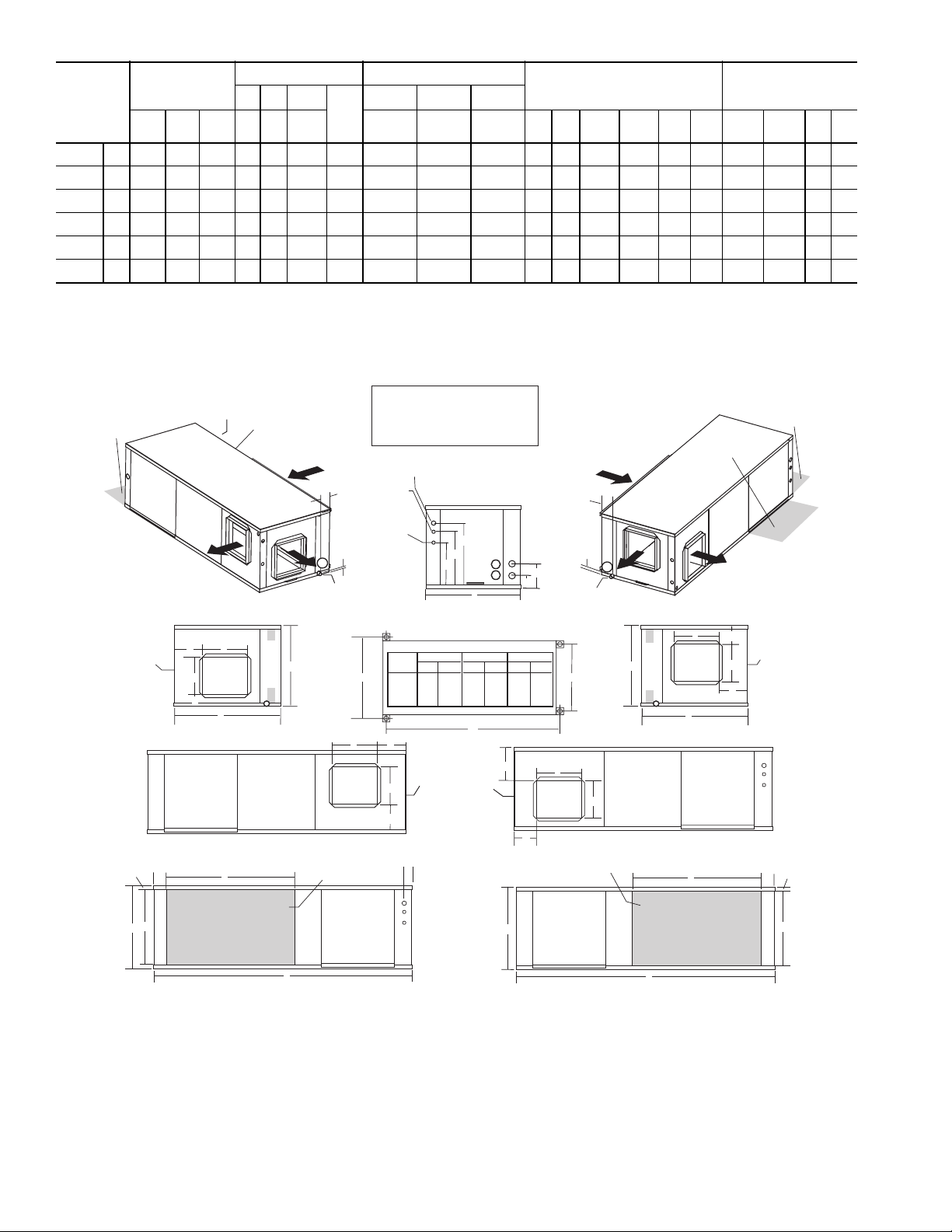
CABINET
A
WidthBDepthCHeightDInEOut
CONNECTIONS
12 3
F
Cond-
ensate
ELECTRICAL KNOCKOUTS (in.)
J
1
Loop
/2conduit
Wate r
FPT
Low
(in.)
Vol ta ge
1
3
3
3
3.5 5.5 8.2 5.8 4.0 5.8 8.0 5.8 1.5 17.1 9.3 2.2 1.0
/
2
3.5 7.5 10.2 5.0 5.6 10.4 9.3 5.0 1.5 17.1 15.3 2.2 1.0
/
4
5.7 9.7 12.2 5.0 6.8 10.4 9.3 5.0 2.1 23.1 17.3 2.2 1.0
/
4
5.7 9.7 12.2 2.9 3.8 13.5 13.1 2.9 1.9 23.1 17.3 2.2 1.0
/
4
5.7 9.7 12.2 2.9 3.8 13.5 13.1 2.9 1.9 32.1 17.3 2.2 1.0
1
8.1 11.7 14.2 5.8 5.0 13.6 13.3 5.8 2.9 36.1 19.3 2.2 1.0
1
K
1
/2conduit
Ext
Pump
L
3
/4conduit
Power
Supply
DISCHARGE CONNECTION
Duct Flange Installed (±0.10 in.)
JKLSupply
Height
M
Supply
Depth
RETURN CONNECTION
Using Return Air Opening
NOPReturn
Depth
Q
Return
Height
RS
2’ [61cm]
Service
Access *
Front
LEFT RETURN RIGHT RETURN
Front
ASP
Right
Discharge
Q
BSP
O
R
Left Return Back Discharge
ASP
V
CSP
Optional 2’ [61cm]
Service Access *
Left Return
Back
Discharge
P
Blower
Outlet
A
Left Return Right Discharge
SU
C
Air Coil Side
3.25
[82.6mm]
F
5
Condensate
3/4”FPT
Blower
Outlet
Air Coil
Power Supply
Legend
K
J
Front-View
CAP=Control Access Panel
CSP=Compressor Service Panel
BSP=Blower Service Panel
ASP=Alternate Service Panel
3 / 4” Knockout
1/2”
Knockout
Low Voltage
1 / 2” Knockout
Unit Hanger Detail
XYZ
MODEL
IN CM IN CM IN CM
006-024 43.1 109.5 24.4 61.9 20.4 51.8
Y
Front
030-036 53.1 134.9 24.4 61.9 20.4 51.8
042-048 62.1 157.7 24.4 61.9 20.4 51.8
060 71.1 180.6 27.4 69.5 23.4 59.4
P
M
BSP
O
N
1
[27.9mm]
2’ [61cm] Service
Front
Access *
Optional 2’ [61cm]
Service Access *
Right Return
Left
Discharge
R
O
Q
CSP
BSP
Front
V
U
3.25
[82.6mm]
L
X
A
CAP
BSP
2
E
1
D
N
M
F
3
Condensate
3/4”FPT
Z
P
Blower
O
Outlet
Right Return Left Discharge
Air Coil
Back
Discharge
P
Blower
C
Outlet
Air Coil Side
A
Right Return Back Discharge
CSP
S
T
C
Left Return Left View -
B
Air Coil Opening
CSP
Front
C
Front
ASP
Right Return Right View -
* Note: Shaded areas are recommended service areas, not required.
B
Air Coil Opening
T
Fig. 1 — 50RHE Dimensional Data
4
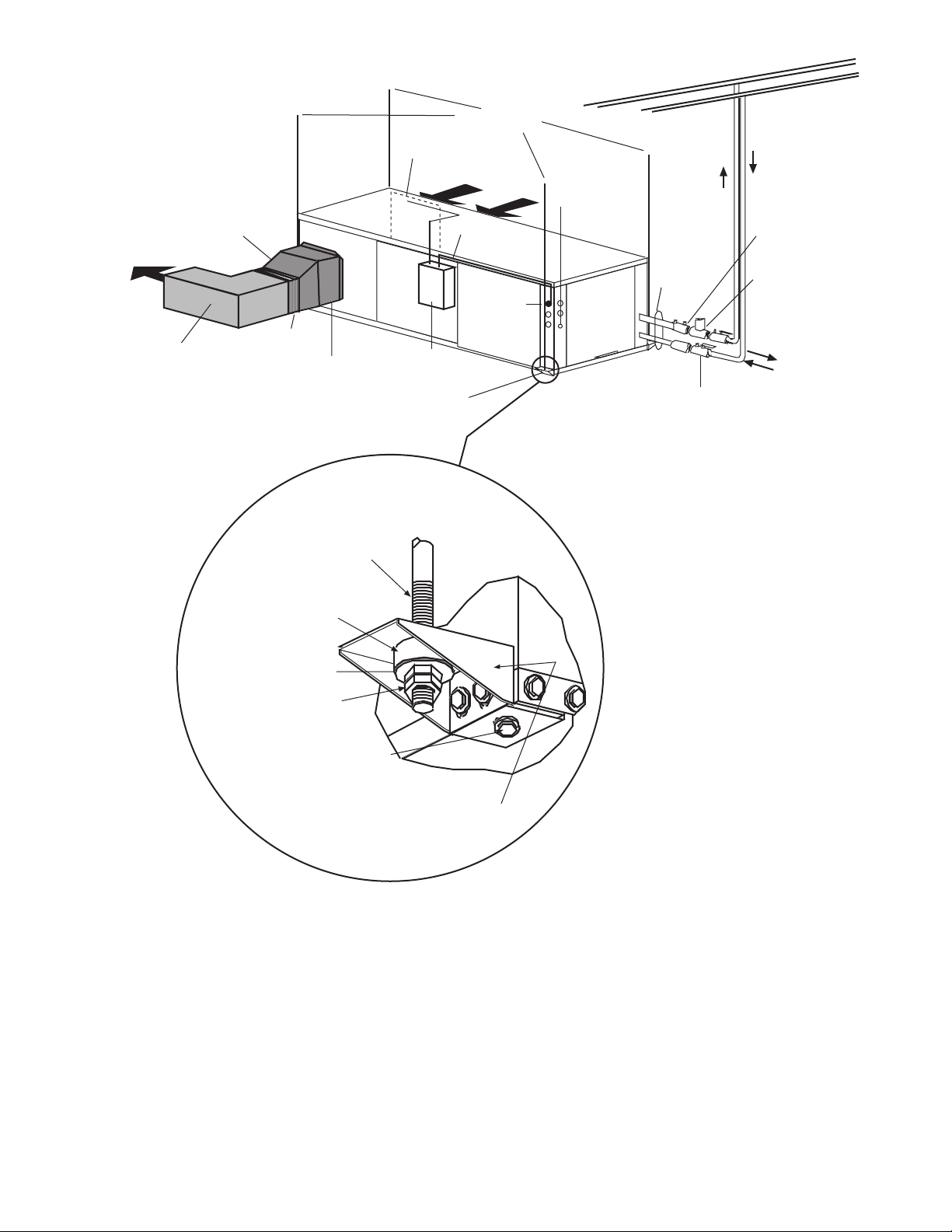
ReturnLoop
Field-supplied transition to
minimize pressure loss
Supply Air
Insulated supply duct with
at least one 90 degree elbow
to reduce air noise
(field supplied)
Flexible
Connection
Field-Supplied
Electric Heat
(if applicable)
3/8” Threaded
Rod (by others)
Filter Access
Power Wiring
Unit Power
Disconnect
Unit Hanger
3/8” threaded rods
(by others)
Return Air
(Ductwork
not shown)
Unit Power
Thermostat
Wiring
Supply Loop
Water In
Water Out
Balancing Valve (Field
Field-supplied
stainless steel
braid hose
with integral
“J” swivel
Ball Valve with optional
integral P/T plug (typical for supply
and return piping)
installed and calibrated
accessory)
Low Pressure Drop Water
Control Valve (optional)
(field-installed accessory)
Water Out
Water In
Vibration Isolator
(white-compressor end
and red-blower end)
size 042-070
Washer
(by others)
Double Hex Nuts
(by others)
50RHR, RHS: Install screw as shown
Sizes 042-060
Optional on smaller sizes
50RHC: Screw must only be
1/2” long to
prevent damage
UNIT HANGER ISOLATION DETAIL
Fig. 2 — Typical Installation — 50RHE Units
Integral hanger supportpre-attached in factory
5
Step 3 — Unit Location — The following guidelines
should be considered when choosing a location for a WSHP
unit:
• Units are for indoor use only
• Locate in areas where ambient temperatures are between
4.4 C and 37.8 C and relative humidity is no greater than
75%
• Provide sufficient space for water, electrical and duct
connections
• Locate unit in an area that allows easy access and
removal of filter and access panels
• Allow enough space for service personnel to perform
maintenance
• Return air must be able to freely enter the space if unit
needs to be installed in a confined area such as a closet
NOTE: Correct placement of the horizontal unit can play an
important part in minimizing sound problems. Since ductwork is normally applied to these units, the unit can be
placed so that the principal sound emission is outside the occupied space in sound-critical applications. A fire damper
may be required by the local code if a fire wall is penetrated.
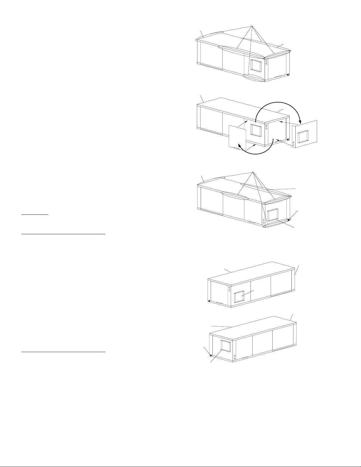
FIELD CONVERSION OF DISCHARGE AIR — The discharge air of the 50RHE horizontal units can be converted
between side and back discharge in the field. The conversion
process is the same for right and left return configurations. See
Fig. 3 and 4.
NOTE: It is not possible to convert return air between left or
right return models in the field due to refrigerant piping
changes.
Preparation
area for conversion. Hung units should be taken down to
ground level before converting.
Side to Back Discharge Conversion
1. Remove screws to free the top and discharge panels. See
2. Remove the access panel and set aside.
3. Lift the discharge panel from side of unit and rotate it to
4. Check blower wire routing and connections for excessive
5. Check refrigerant tubing for contact with other compo-
6. Reinstall top panel using screws set aside in Step 1.
NOTE: Location for some screws at bottom of discharge panel
may have to be changed.
7. Manually spin fan wheel to check for obstructions.
8. Replace access panel.
Back to Side Discharge Conversion
above for Side to Back Discharge Conversion, noting the
panels would be reversed.
— The unit should be on the ground in a well lit
Fig. 3.
back using care not to damage blower wiring.
tension or contact with sheet metal edges. Re-route if
necessary.
nents. Adjust if necessary.
Adjust for any obstruction found.
— Follow instructions
Water
Connection End
Side Discharge
Water
Connection End
Water
Connection End
Back Discharge
Remove Screws
Return Air
Move to Side
Replace Screws
Fig. 3 — Conversion Left Return,
Side Discharge to Back Discharge
Return Air
Supply
Duct
Side Discharge
Return Air
Drain
Discharge Air
Back Discharge
Return Air
Rotate
Connection End
Return Air
Drain
Discharge Air
Water
Connection End
Water
Fig. 4 — Conversion Right Return,
Side Discharge to Back Discharge
6
Step 4 — Mounting the Unit — Horizontal units
should be mounted using the factory-installed hangers. Proper
attachment of hanging rods to building structure is critical for
safety. See Fig. 2 and 5. Rod attachments must be able to support the weight of the unit. See Table 1 for unit operating
weights.
Step 5 — Duct System — Size the duct system to han-
dle the design airflow quietly.
NOTE: Depending on the unit, the fan wheel may have a shipping support installed at the factory. This must be removed
before operating unit.
SOUND ATTENUATION — To eliminate the transfer of
vibration to the duct system, a flexible connector is recommended for both discharge and return air duct connections on
metal duct systems. The supply and return plenums should
include internal duct liner of fiberglass or be made of duct
board construction to maximize sound attenuation of the
blower. Installing the WSHP unit to uninsulated ductwork in an
unconditioned space is not recommended since it will sweat
and adversely affect the unit’s performance.
To reduce air noise, at least one 90 degree elbow could be
included in the supply and return air ducts, provided system
performance is not adversely impacted. The blower speed can
also be changed in the field to reduce air noise or excessive airflow, provided system performance is not adversely impacted.
EXISTING DUCT SYSTEM — If the unit is connected to
existing ductwork, consider the following:
• Verify that the existing ducts have the proper capacity to
handle the unit airflow. If the ductwork is too small,
install larger ductwork.
• Check existing ductwork for leaks and repair as
necessary.
NOTE: Local codes may require ventilation air to enter the
space for proper indoor air quality. Hard-duct ventilation may
be required for the ventilating air supply. If hard ducted ventilation is not required, be sure that a proper air path is provided
for ventilation air to unit to meet ventilation requirement of the
space.
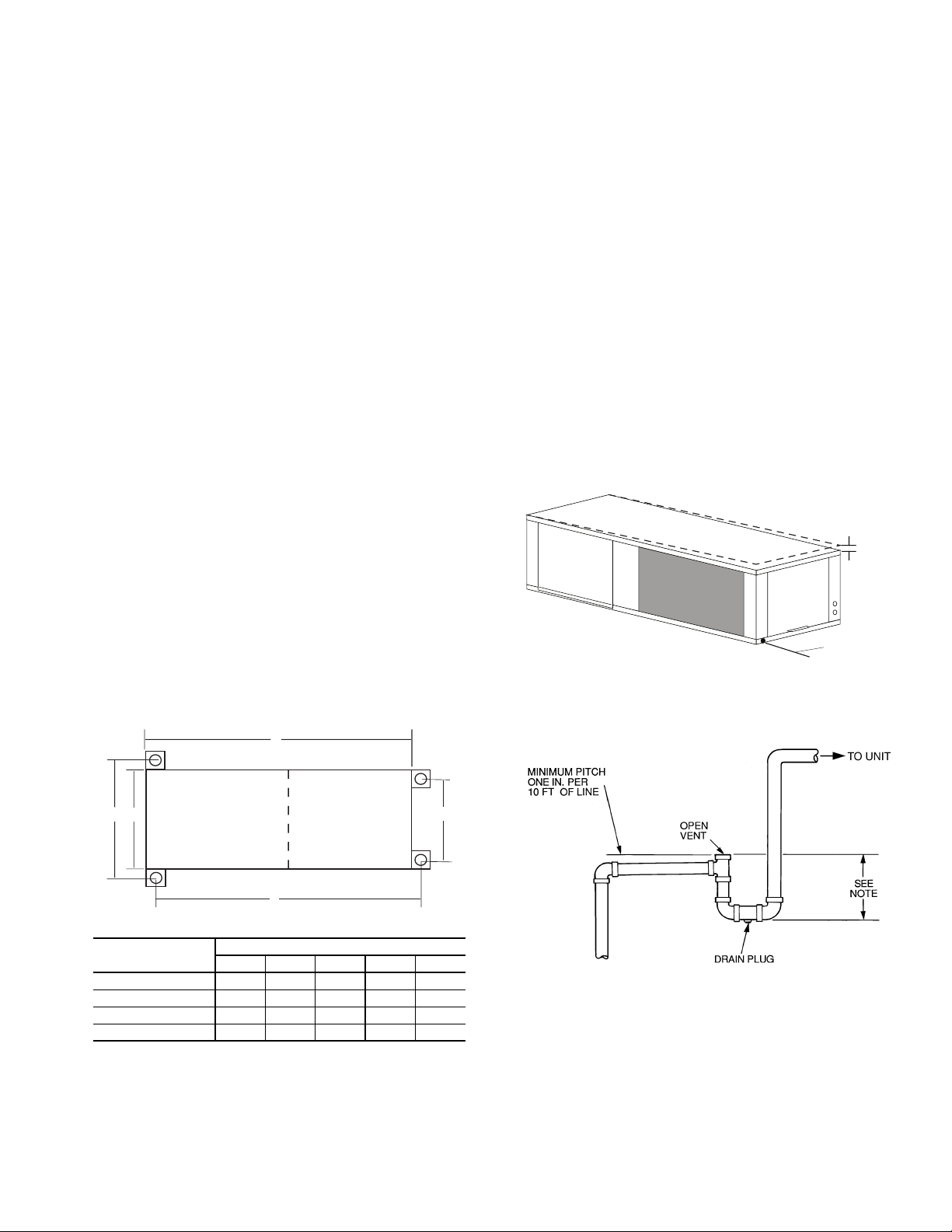
Step 6 — Condensate Drain — Slope the unit to-
ward the drain at a 6.5 mm per 30 cm pitch. See Fig. 6. If it is
not possible to meet the required pitch, install a condensate
pump at the unit to pump condensate to building drain.
Horizontal units are not internally trapped; therefore an external trap is necessary. Install each unit with its own individual
trap and means to flush or blowout the condensate drain line.
Do not install units with a common trap or vent. For typical
condensate connections see Fig. 7.
NOTE: Never use a pipe size smaller than the connection.
VENTING — Install a vent in the condensate line of any
application that may allow dirt or air to collect in the line. Consider the following:
• Always install a vent where an application requires a
long horizontal run.
• Always install a vent where large units are working
against higher external static pressure and to allow
proper drainage for multiple units connected to the same
condensate main.
• Be sure to support the line where anticipated sagging from
the condensate or when “double trapping” may occur.
• If condensate pump is present on unit, be sure drain con-
nections have a check valve to prevent back flow of con-
densate into other units.
65 mm Pitch for
Drainage
Pitch Toward
Drain
Drain Connection
Fig. 6 — Horizontal Unit Pitch
D
D
A
C
50RHE UNITS
Compressor
Section
ABCDE
006-024 568 1095 619 1095 518
030,036 568 1349 619 1349 518
042,048 568 1577 619 1577 518
060 645 1806 695 1806 594
Air Handler
Section
B
DIMENSIONS (mm)
Fig. 5 — Horizontal Hanger Bracket
(Factory Installed)
E
NOTE: Trap should be deep enough to offset maximum unit static
difference. A 102 mm trap is recommended.
Fig. 7 — Trap Condensate Drain
7
Step 7 — Piping Connections — Depending on the
application, there are 3 types of WSHP piping systems to
choose from: water loop, ground-water and ground loop. Refer
to Piping Section of Carrier System Design Manual for additional information.
All WSHP units use low temperature soldered female pipe
thread fittings for water connections to prevent annealing and
out-of-round leak problems which are typically associated with
high temperature brazed connections. Refer to Table 1 for
connection sizes. When making piping connections, consider
the following:
• Use a backup wrench when making screw connections to
unit to prevent internal damage to piping.
• Insulation may be required on piping to avoid condensa-
tion in the case where fluid in loop piping operates at
temperatures below dew point of adjacent air.
• Piping systems that contain steel pipes or fittings may
be subject to galvanic corrosion. Dielectric fittings
should be used to isolate the steel parts of the system to
avoid galvanic corrosion.
WATER LOOP APPLICATIONS — Water loop applications
usually include a number of units plumbed to a common piping system. Maintenance to any of these units can introduce air
into the piping system. Therefore, air elimination equipment
comprises a major portion of the mechanical room plumbing.
The flow rate is usually set between 0.040 and 0.054 l/s per
kW of cooling capacity. For proper maintenance and servicing,
pressure-temperature (P/T) ports are necessary for temperature
and flow verification.
In addition to complying with any applicable codes, consid-
er the following for system piping:
• Piping systems using water temperatures below 10 C
require 12.7 mm closed cell insulation on all piping
surfaces to eliminate condensation.
• Avoid all plastic to metal threaded fittings due to the
potential to leak. Use a flange fitted substitute.
• Teflon tape thread sealant is recommended to minimize
internal fouling of the heat exchanger.
• Use backup wrench. Do not overtighten connections.
• Route piping to avoid service access areas to unit.
• Flush the piping system prior to operation to remove dirt
and foreign materials from the system.
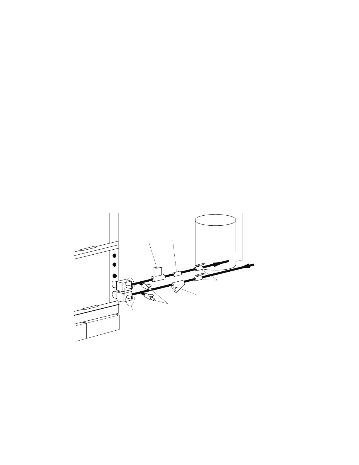
GROUND-WATER APPLICATIONS — Typical groundwater piping is shown in Fig. 8. In addition to complying
with any applicable codes, consider the following for system piping:
• Install shut-off valves for servicing.
• Install pressure-temperature plugs to measure flow and
temperature.
• Connect boiler drains and other valves using a “T” connector to allow acid flushing for the heat exchanger.
• Do not overtighten connections.
• Route piping to avoid service access areas to unit.
• Use PVC SCH80 or copper piping material.
NOTE: PVC SCH40 should not be used due to system high
pressure and temperature extremes.
Water
Control
Valve
PressureTemperature
Plugs
Flow
Regulator
Boiler
Drains
Pressure
Tank
Water Out
Shut-Off
Valve
Strainer – Field-Installed Accessory
(16 to 20 mesh recommended for
filter sediment)
Fig. 8 — Typical Ground-Water Piping Installation
Water In
From Pump
8
Water Supply and Quantity
— Check water supply. Water
supply should be plentiful and of good quality. See Table 2 for
water quality guidelines.
Step 8 — Electrical Wiring
IMPORTANT: Failure to comply with the above required
water quality and quantity limitations and the closedsystem application design requirements may cause damage
to the tube-in-tube heat exchanger that is not the responsibility of the manufacturer.
In all applications, the quality of the water circulated
through the heat exchanger must fall within the ranges listed in
the Water Quality Guidelines table. Consult a local water treatment firm, independent testing facility, or local water authority
for specific recommendations to maintain water quality within
the published limits.
GROUND-LOOP APPLICATIONS — Temperatures between
–4 to 43 C and a liquid flow rate of 0.040 to 0.054 l/s per kW of
cooling capacity is recommended. In addition to complying
with any applicable codes, consider the following for system
piping:
• Limit piping materials to only polyethylene fusion in the
buried sections of the loop.
• Do not use galvanized or steel fittings at any time due to
corrosion.
• Avoid all plastic to metal threaded fittings due to the
potential to leak. Use a flange fitted substitute.
• Do not overtighten connections.
• Route piping to avoid service access areas to unit.
• Use pressure-temperature (P/T) plugs to measure flow of
pressure drop.
To avoid possible injury or death due to electrical shock,
open the power supply disconnect switch and secure it in
an open position during installation.
Use only copper conductors for field-installed electrical
wiring. Unit terminals are not designed to accept other
types of conductors.
All field installed wiring, including the electrical ground,
MUST comply with applicable local, national and regional
codes.
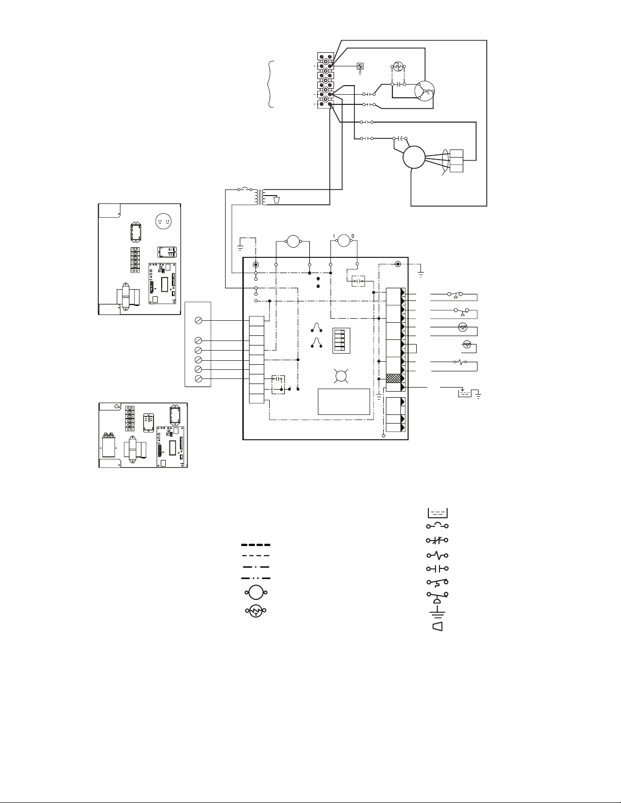
Refer to unit wiring diagrams Fig. 9-12 for a schematic of
the field connections, which must be made by the installing (or
electrical) contractor. Refer to Electrical Data for fuse sizes.
Consult the unit wiring diagram located on the inside of the
compressor access panel to ensure proper electrical hookup.
The installing (or electrical) contractor must make the field
connections when using field-supplied disconnect.
Operating voltage must be the same voltage and phase as
shown in Electrical Data shown in Table 3.
Make all final electrical connections with a length of flexible conduit to minimize vibration and sound transmission to
the building.
Table 2 — Water Quality Guidelines
CONDITION ACCEPTABLE LEVEL
pH 7 to 9 range for copper. Cupronickel may be used in the 5 to 9 range.
Tota l
Hardness
Iron Oxides Less than 1 ppm.
Iron Bacteria No level allowable.
Corrosion* Max Allowable Level Coaxial Metal
Brackish Use Cupronickel heat exchanger when concentrations of calcium or sodium chloride are
*If the concentration of these corrosives exceeds the maximum allowable level, then the potential for serious cor-
rosion problems exists.
†Sulfides in the water quickly oxidize when exposed to air, requiring that no agitation occur as the sample is
taken. Unless tested immediately at the site, the sample will require stabilization with a few drops of one Molar
zinc acetate solution, allowing accurate sulfide determination up to 24 hours after sampling. A low pH and high
alkalinity cause system problems, even when both values are within ranges shown. The term pH refers to the
acidity, basicity, or neutrality of the water supply. Below 7.0, the water is considered to be acidic. Above 7.0,
water is considered to be basic. Neutral water contains a pH of 7.0.
NOTE: Hardness in mg/l is equivalent to ppm.
Calcium and magnesium carbonate should not exceed 350 ppm.
Ammonia, Ammonium Hydroxide 0.5 ppm Cu
Ammonium Chloride, Ammonium Nitrate 0.5 ppm Cu
Ammonium Sulfate 0.5 ppm Cu
Chlorine/Chlorides 0.5 ppm CuNi
Hydrogen Sulfide† None Allowable —
greater than 125 ppm are present. (Seawater is approximately 25,000 ppm.)
9
COMPONENT LOCATION
CR
CAP
PB
TRANS
SIZES: 015-036
PB
CAP
CR
BR
BR
CXM
SEE
NOTE 5
TYPICAL
T-S TAT
Y
O
G
R
C
L
SEE NOTE 6 FOR
DRY ALARM CONTACT
CXM
POWER SUPPLY
REFER TO
DATA PLATE
USE COPPER
CONDUCTORS
ONLY
SEE NOTE 3
CB*
24V
BLU
SEE
NOTE 7
C
R
COMPR.
COOLING
FAN
24 VAC
COMMON
ALARM
AL1
AL2
Y
W
O
G
R
C
A
PI
EARTH (GRD)
TRANS
Y
ALARM
RELAY
N (NEUTRAL)
L
BLKYEL
RED
220V
ORG
240V
10
BR
GRY
BRN
BR BRG CCG
TEST PINS
SEE
NOTE 4
JW3
FP1
LOW TEMP
JW2
FP2
LOW TEMP
JWI
SEE
NOTE
6
G/Y
PB
6
G/Y
5
4
YEL
3
RED
2
BLK
1
BLK
CR
BRN
YEL
CC
COMPRESS.
RELAY
DIP SWITCH
PM
1
STAGE 2
2
NOT USED
3
NOT USED
4
1OR3
5
TRIES
OFF ON
STAT US
G
LED
CXM
MICRO-
PROCESSOR
CONTROL LOGIC
STARTASSIST
(WHEN NEEDED)
RED* BLU*
RED BLU
68
CR
24
BLK
24
BR
YEL
68
YEL OR WHT
HP
LOC
FP1
FP2
RV
CO
24V
DC
EH1
EH2
CO
CAP
S
R
RED
COMPRESSOR
CAPACITOR
BRN
PSC
FAN
MTR
3 AIR FLOW SETTINGS
(FCTRY SETTING - MED)
SEE NOTE 8
SEE
NOTE 7
1
RED
RED
2
3
BLU
BRN
4
5
GRY
GRY
6
VIO
7
(
CAP -TUBE
UNITS)OR
8
9
BRN
10
ORG
NOT USED
12
P2
P3
C
YEL
L(3
M(2
H(1
VIO
VIO
)
BLU
)
)
G/Y
SEE NOTE 4
(
HP
LOC
FP1
TXV UNITS
FP2
RVS
CO
)
TRANS
SIZES: 006, 009, 012
AL — Alarm Relay Contacts
BR — Blower Relay
CAP — Compressor Capacitor
CB — Circuit Breaker
PM — Performance Monitor
PSC — Permanent Split Capacitor
RVS — Reversing Valve Solenoid
TRANS — Transformer Optional Wiring
CC — Compressor Contactor
CO — Sensor, Condensate Overflow
FP1 — Sensor, Water Coil Freeze Protection
FP2 — Sensor, Air Coil Freeze Protection
GND — Ground
HP — High-Pressure Switch
JW — Clippable Field Selection Jumper
LOC — Loss of Charge Pressure Switch
P1 — Field Wiring Terminal Block
PB — Power Block
*Optional wiring.
NOTES:
1. Compressor and blower motor thermally protected internally.
2. All wiring to the unit must comply with NEC and local codes.
3. Transformer is wired to 240 v (ORG) lead for 240/50/1 units,
switch RED and ORG leads to PB(1) and insulate ORG lead.
4. FP1 thermistor provides freeze protection for water. When using
antifreeze solutions, cut JW3 jumper.
5. Typical heat pump thermostat wiring shown. Refer to thermostat
installation instructions for wiring to the unit.
Fig. 9 — Typical Aquazone™ Complete C Control Wiring (Single-Phase Unit)
LEGEND
Condensate Pan
Circuit Breaker
Field Line Voltage Wiring
Field Low Voltage Wiring
Printed Circuit Trace
Optional Wiring
Relay/Contactor Coil
Thermistor
Relay Contacts — N.C.
Solenoid Coil
Relay Contacts — N.O.
Switch Temperature
Switch Low Pressure
Ground
Wire Nut
6. 24-v alarm signal shown. For dry alarm contact, cut JW1 jumper,
and dry contact will be available between AL1 and AL2.
7. Transformer secondary ground via microprocessor board standoffs and screws to control box. (Ground available from top two
standoffs as shown.)
8. Fan motors factory wired for medium speed. For high or low
speed remove BLU wire from fan motor speed tap “M” and connectto“H”forhighor“L”forlow.
10
 Loading...