

Page 1
Carrier Corporation • Syracuse N Y 13221
Single-Package Heat Pumps
Chassis Only (Install ONLY after
50OT wall sleeve is in place)
CONTENTS
Page
SAFETY CONSIDERATIONS
INTRODUCTION .......................................................1
INSTALLATION.......................................................1-4
Step 1 — Check Equipment and Jobsite .. I
• UNPACK UNIT
• INSPECT EQUIPMENT
• INSPECT WALL SLEEVE
Step 2 — Install Chassis in Wall Sleeve.... 3
• SLIDE CHASSIS INTO SLEEVE
Step 3 — Install Thermostat and
Connect Thermostat Wiring....................................3
• TO MOUNT THERMOSTAT IN UNIT
• TO MOUNT THERMOSTAT
REMOTELY
COLD CLIMATE ACCESSORY
START-UP
SERVICE
.................................................................
.................................................................
..................................
................................
1
4
4
4-14
SAFETY CONSIDERATIONS
Installation and servicing of air conditioning
equipment can be hazardous due to system pressure
and electrical components. Only trained and quali
fied service personnel should install, repair or
service air conditioning equipment.
servke <ar
dixsr ’Tvm ^ feoatsr
mwst 4cfm bdoxa ^
WARNii^C: The 5QQT is.
uatt astd, thsr^ore, req«*res special casse m
liasEtdSas^ to lo asad
clastaags lo oast, Avcàé ìsspact visàì% or
other stapdmg «bjects whs® cissssim
INTRODUCTION
Install Model 50QT112, 115 and 118 heat pump
chassis in 50QT wall sleeve. Part No. 50QT900060;
and Model 50QT124 and 130 chassis in 50QT wall
sleeve. Part No. 50QT900080. Wall sleeves are
shipped separately with aecompanying installation
instructions. All electrical power, ductwork and
condensate drain hookups are made at time of wall
sleeve installation.
Untrained personnel can perform basic mainte
nance functions of cleaning indoor coil or replacing
filter. All other operations should be performed
by trained service personnel. When working on air
conditioning equipment, observe precautions in the
literature, tags and labels attached to the unit and
other safety precautions that may apply.
Follow all safety codes. Wear safety glasses
and work gloves. Use quenching cloth for brazing
operations. Have fire extinguisher available for
all brazing operations.
>P Carrier Corporation 1984
Bart
aad so '
is iiìsiaJled, isso? cm
pr^^per
<md<m m piace.
INSTALLATION
Step 1 — Check Equipment and Jobsite
UNPACK UNIT — Move to final loeation. Lift
eardboard carton off chassis taking special care not
to damage unit.
Form 50QT-10SI
Page 2
Table 1 — Electrical Data (&©^zt
MODEL
50QT
AB
112300 II
115300
AB
118300 AD
AF
AD
124300 AF
AG
AD
130300 AF
AG
♦Permissible limits of the voltage range at which units will
operate satisfactorily
fField wiring to be sized for NEC or local codes Use copper wire
only
^Maximum dual element fuse
♦♦Minimum voltage is 197 when outdoor ambient temperature
exceeds 105 F
NOTE: Dual values in this table (for example Electric Fleeter Amps
9 4/12 5) apply to 208- and 230-volt connections respectively
V/PH
208/230/1
208/230/1
208/230/1
208/230/1
208/230/1
OPER
VOLTAGE^
Max Min^*
254 187 37 6 8 1 5 1 0
254
254
254 187 59 13 0 2 0
254
187
187
187
COMPR
LRA
43 8 7
49
79
IFM OFM
RLA FLA
1 5
10 3
1 7
16 9 2 4
ELECTRIC
HEATER
AMPS
FLA
9 4/12 5
18.0/20.8
1 0
1 0
1 5
1 5
9 4/12 5
18 0/20 8
9 4/12 5
18 0/20 8
26 8/31 3
17 3/20 8
26 8/31 3
36 1/41.7
17 4/ 20 8
26 8/31 3
36 0/41 7
FLA — Full Load Amps
FIACR— Heating, Air Conditioning
IFM — Indoor Fan Motor
Max Fuse or
.....
These units require 2 separate supply circuits
Refer to BOTFI branch circuit charts for complete
electrical data
and Refrigeration
BRANCH CIRCUIT #1
(or Total Unit)t
HACR Ckt
Bkr Ampst
25/30
35/40
25/30
35/40
30/35
40/45
50/55
45/50
55/60
MCA
22 8/26 6
33.5/37.0
25 1/29 0
35.9/39.4
27 3/31 2
38 1/41 6
49 1/54 7
41 4/45 9
53.6/59.1
50/55 ^ 1 47.5/52J
BRANCH CIRCUIT #2
(When Used)t
Max Fuse or
HACR Ckt
Bkr Ampst
—
—
—
LRA — Locked Rotor Amps
MCA— Minimum Circuit
Amps
OFM — Outdoor Fan Motor
RLA — Rated Load Amps
MCA
—
—
—
1
♦INSPECT EQUIPMENT for damage prior to in
stallation. To remove plastic wrapper, grasp bottom
and pull out until velcro strips separate. To remove
metal cover plate, remove 6 screws. Eile claim with
shipping company if shipment is damaged or
incomplete.
Leave chassis bolted to skid and replace metal
cover plate, plastic wrapper, and carton until ready
for installation into wall sleeve.
INSPECT WALL SLEEVE installation for
damage. Condensate drain pan must be free of
debris and installed in accordance with local build
ing regulations. Electrical connector on left side of
sleeve should be free of dirt, grease, paint, etc.
Connector must be properly wired before chassis
installation. Duct connection panel must be level
and duct connections complete. Do not rest weight
of ductwork on duct connector panel. Inspect name
plate on sleeve to ensure wire and fuse sizing is
correct for model size to be installed.
At ^
-i
Fig. 1 — Chassis with Indoor Plastic Wrapper
©
Page 3
Step 2 — Install Chassis in Wall Sleeve —
Remove sleeve filler panel and save screws. Install
outdoor grille using these screws. Remove indoor
plastic wrapper as described in Step 1. Do not
handle cha.ssis with plastic wrapper in place.
SLIDE CHASSIS INTO SLEEVE — Chassis is
heavy. Portable lifting device must be used. Exercise
caution to make sure forks do not damage chassis
components (such as drain connections) while
lifting and installing. Guide chassis into sleeve on
indoor side by first placing chassis guide channels
onto sleeve guide channels at bottom of sleeve.
Slide chassis into sleeve until center partition peri
meter meets gasket provided around outer edge of
sleeve. Check electrical plugs for alignment as
chassis is slid into place.
Tighten chassis into place by driving 6 screws,
provided in separate bag with chassis, into nuts
provided on sleeve (see Fig. 3).
Electrical and condensate drain connections are
complete when chassis is installed correctly into
sleeve.
Step 3 — Install Thermostat and Connect
Thermostat Wiring — (Thermostat and subbase
are packaged separately with unit shipment.)
Thermostat can be installed in 50QT or in remote
location.
TO MOUNT THERMOSTAT IN UNIT;
1. Remove metal cover plate by removing 6 screws.
2. Locate and install subbase onto thermostat
bracket running between right and left coil par
tition (see Fig. 3). Push plug and wires through
hole provided.
3. Connect plug from subbase to mating socket
located on left coil partition (see Fig. 3).
4. Attach thermostat to subbase and snap on
thermostat cover.
5. Cut hole in stenciled area on back side of wrapper
with a sharp utility knife.
6. Cut and remove insulation from hole in metal
cover plate.
7. Replace metal cover plate.
TO MOUNT THERMOSTAT REMOTELY:
1. Pull subbase extension cord, previously installed,
up into the return air inlet. Plug cord into mating
socket on the left-hand coil partition. (See Fig. 3.)
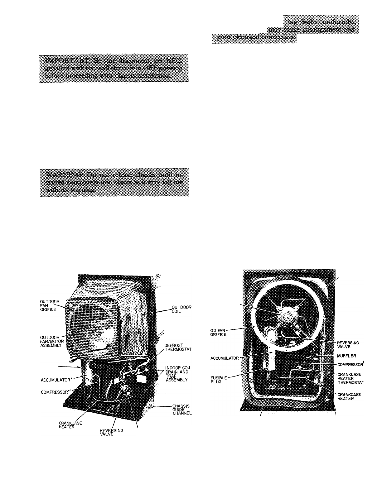
FUSIBLE-
PLUG
CRANKCASE HEATER
THERMOSTAT
50QT112, 115, 118
^Accumulator and compressor location reversed on 50QT112
tCompressor guard removed
Fig. 2 — Outdoor Component Location
OUTDOOR
COIL
00 FAN MOTOR
(PROPELLER
FAN REMOVED
TO SHOW
MOTOR)
COMPRESSOR MOUNTING
PAN
CHASSIS GUIDE
CHANNEL
50QT124, 130
^Outdoor fan guard and compressor guard removed to show
components
Page 4
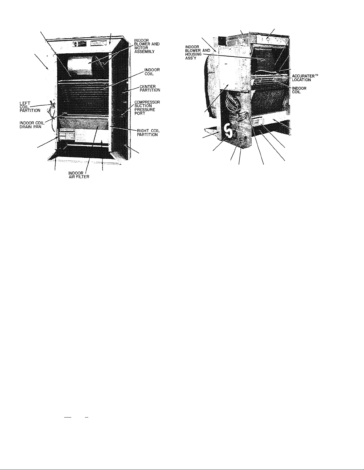
ACCURATER
LOCATION
MAIN
CONTROL BOX
COVER
MATING
SOCKET
LOCATION
INDOOR NAMEPLATE
LOCATION
THERMOSTAT
MOUNTING BRACKET
50QT112,115,118
ELECTRIC HEATER
CONTROL BOX COVER
CHASSIS
MOUNTING
BOLTS
(6 TOTAL)
SLEEVE ELECTRIC HEATER
JUNCTION LOCATION
BOX ACCESS
PLATE
MAIN
CONTROL
BOX
(SLIDES OUT
FOR servicing:
CENTER
PARTITION
INDOOR COIL
CONDENSATE
DRAIN
LEFT COIL PARTITION
INDOOR NAMEPLATE LOCATION
Fig. 3 — Indoor Component Location
THERMOSTAT PLUG
50QT124,130
ELECTRIC HEATER COVER
./INDOOR FAN
MOTOR
(NOT VISIBLE)
DEFROST
/THERMOSTAT ON
LIQUID LINE
LOW-PRESSURE
SWITCH
v(NOT SHOWN)
^COMPRESSOR
SUCTION
SERVICE PORT
BRIGHT COIL
■ PARTITION
ROOM THERMOSTAT
(CAN BE MOUNTED
REMOTELY)
INDOOR AIR FILTER
2. Plug other end of cord, hanging from the wall at
its remote location, securely into subbase.
3. Push plug and excess leads into wall hole. Cover
hole appropriately to avoid incorrect thermostat
readings.
4. Mount subbase onto wall.
5. Attach thermostat to subbase. Snap on cover
and install chassis indoor cover.
> COLD CLIMATE ACCESSORY
Cold climate accessory should be installed on
50QT100 units where the outdoor ambient tem
perature consistently falls below 30 F. Cold climate
accessory is available in both six packs and single
packs as indicated below: for 50QT112, 115, 118 —
accessory part no. 50QT90016106 (six pack) or
50QT900160 (single pack); for 50QT124, 130 —
accessory part no. 50QT90017106 (six pack) or
50QT900170 (single pack).
START-UP
Crankcase Heater — The 50QT compressor is
equipped with a crankcase heater that is thermo
statically activated in cold weather. (See Fig. 2 and
3.) If temperature is below 65 F, operate crankcase
heater 24 hours before starting unit. To energize
crankcase heater only, after chassis installation, set
thermostat to <C > ^position and turn on unit
power at disconnect switch.
Thermostat Anticipator — Room thermostat
anticipator settings for all 50QT heat pumps is
0.20 amps. This setting may be changed slightly to
provide a greater degree of comfort fora particular
installation.
To Start Unit — Check that main power is on and,
if temperature is below 65 F, that compressor
crankcase heater has been energized for at least
24 hours.
1. Set selector switch at*C •
2. Set fan switch as desired (FAN) (AUTO.).
3. Set thermostat lever at the desired temperature.
4. Set selector switch at HEAT or COOL. Check
system refrigerant charge. See Refrigerant
Charging.
SERVICE
Low-Pressure Switch (Safety Control) is lo
cated on liquid line downstream of AccuRater™
control during cooling mode (or upstream of Accu
Rater control during heating mode). Switch opens
at 5 psig and shuts down compressor to protect it
from overheating if refrigerant charge is too low.
High and low side pressure connections are acces
sible from the incloor portion of the unit for
charging. (See Fig. 3.)
High-Pressure Relief Valve (Safety Control) is
located in compressor. Relief valve opens at a pres
sure differential of approximately 450 ± 50 psi
between suction (low side) and discharge (high side)
to allow pressure equalization.
Internal Current and Temperature Sensitive
Overload (Safety Control) re.sets automatically
when compressor motor temperature drops to a safe
level (overloads may require up to one hour to reset).
#
Page 5
#
When an internal overload is suspected of being
open, check by using an ohmmeter or continuity
tester. If necessary, refer to Carrier Standard
Service Techniques Manual, Chapter 2, Electrical,
for complete instructions.
Defrost Control, consisting of a defrost timer,
defrost thermostat and defrost relay, interrupts
normal system heating operation to remove frost
and ice formation on outdoor coil. Frost impairs
unit performance. Defrost control simultaneously
stops outdoor fan, energizes reversing valve sole
noid to switch system into cooling cycle (outdoor
unit as condenser, indoor unit as evaporator),
and activates electric heater. Unit can defrost
every 90 minutes, but will do so only if outdoor
temperatures are in the frosting temperature zone.
For heat pump to defrost, 2 conditions are
necessary:
1. Defrost timer contacts must be closed.
2. Coil temperature must be cold enough to cause
defrost thermostat contacts to close.
Contacts close at 28 ±3 F (50QT112 - 118) and
35 ± 3 F (50QT124, 130). Every 90 minutes of
elapsed running time, the defrost timer contacts
close for 10 seconds. If the defrost thermostat
contacts are closed, the unit defrosts. The defrost
timer limits defrosting period to 10 minutes.
Normally the frost is removed and the defrost ther
mostat contacts will open to terminate defrosting
before 10 minutes have elapsed. Defrost thermostat
contacts open at 65 ±5F (50QT112 - 118) and
75 ±5F (50QT124,130). When defrosting is
terminated, the outdoor fan motor is energized
and reversing valve solenoid is de-energized, re
turning unit to heating cycle.
HEAT PUMP CIRCUITS shown in Fig. 4 are
refrigerant flow diagrams for heating and cooling
cycles.
Refrigerant Charging
CAtlTiOf^; To pfeveat persotial fejury. 'wear
safeij; giasoe» ao<3 giovfes ha»d3t»g
Do not overcharge system. An overcharge can
cause compressor flooding.
Unit refrigerant system is factory charged. When
recharging is necessary, weigh in total charge indi
cated in Table 2. (Charge must be weighed in during
heating season.) Remove any refrigerant remaining
in system before recharging. If system has lost com
plete charge, triple-evacuate system to 5000 microns
(29.7 in. vacuum) before recharging. Service port
connections are provided on unit suction and dis
charge lines for evacuation and charging. (See Fig. 4
for service port location.) Dial-a-charge charging
cylinder is an accurate device used to recharge
systems by weight. These cylinders are available at
refrigeration supply firms.
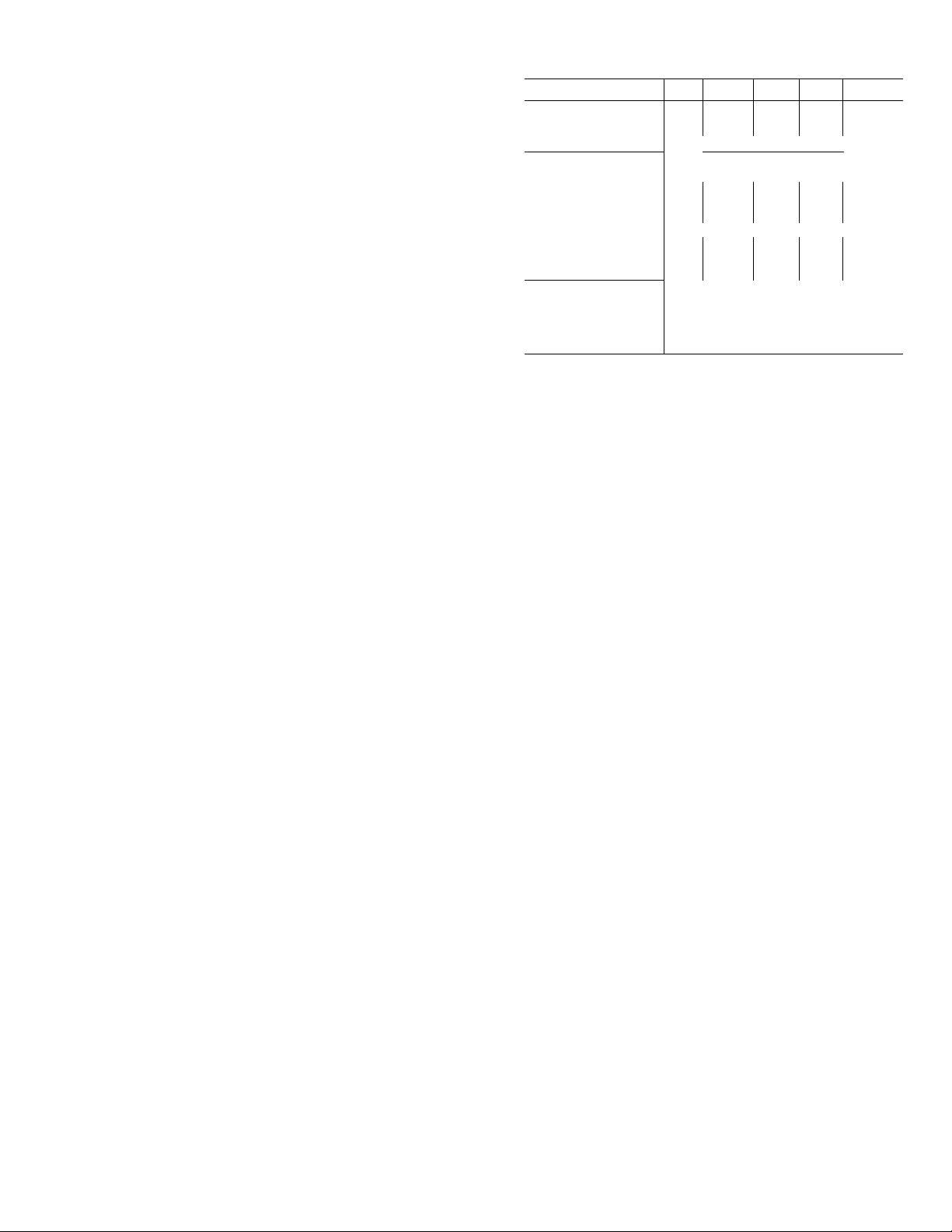
Table 2 — Service Data
UI\IIT50QT 112
MODEL
R-22 CHARGE* (lb) 2 7 2 7 3 2
Refrig Control AccuRater™ Bypass Type
INDOOR FAN Centrifugal Blower,
Rotationt
Rpm
Diameter (in )
Width (in.)
Range (cfm)
Motor Hp
OUTDOOR FAN
Cfm
Rpm 1125
Diameter (in )
Motor Hp Vs
ccw
cw
Counterclockwise
Clockwise
1580
430/
375
1700
115
300
300
Direct Drive, 2-Speed
CW CW CCW
CW
1550 1570 1675
6
6
550/ 575/
475 480
'A Vs.
'A
Propeller, Direct Drive, Single Speed
1700 1700 2000 2000
‘Factory refrigerant charge
fLooking at fan motor shaft
118
300
6
8
15
124 130
300 300
4 5
CCW
1675
7 7
885/
800
1025/
'/4 V4
47
960
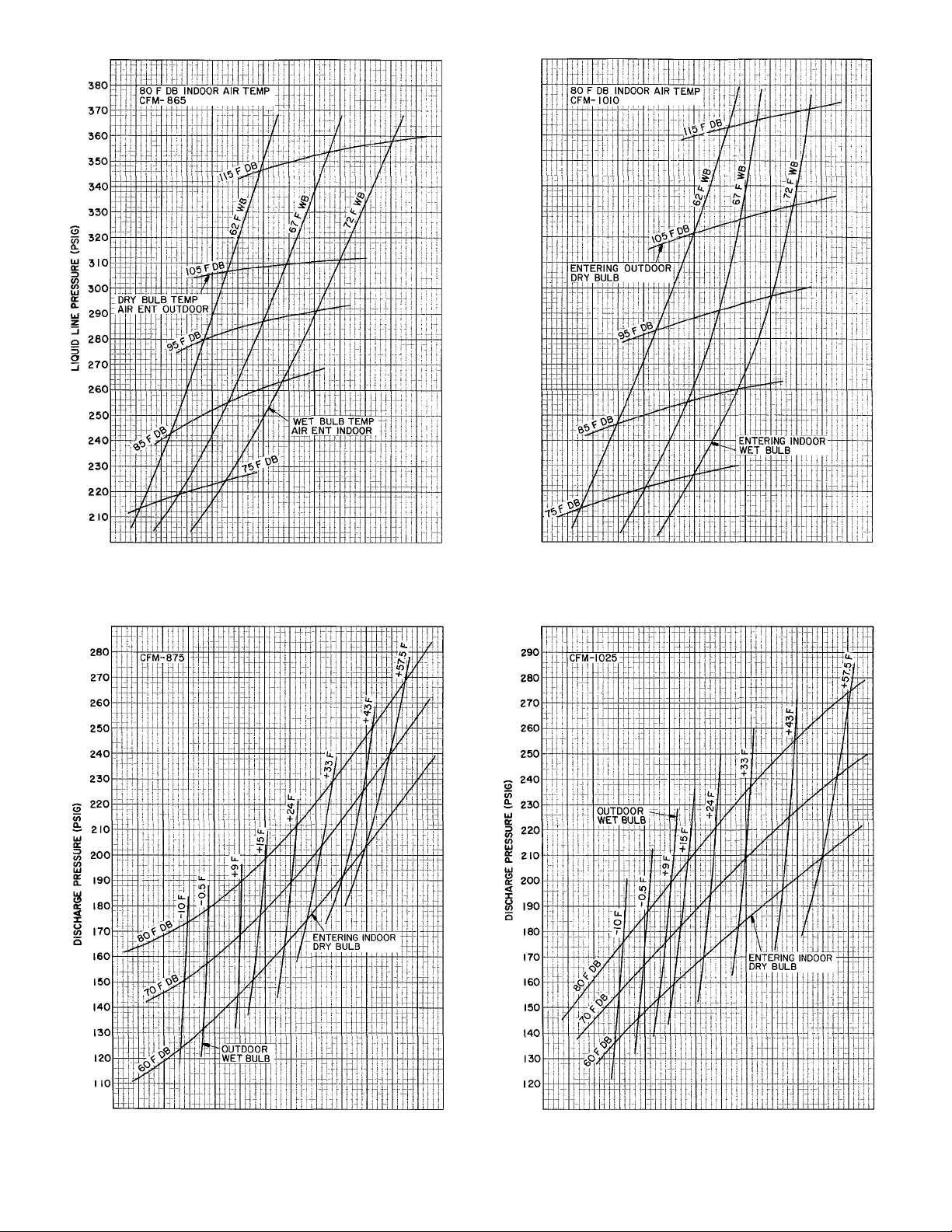
To check and/or adjust charge during cooling
season, use Cooling Cycle Charging Charts (Fig. 5,
7, 9, II, 13) and follow Charging Chart Method
below. The charging chart may also be used as an
alternate method of recharging system.
To check system operation during heating cycle,
use Heating Cycle Operation Check Chart (Fig. 6, 8,
10, 12, 14). These charts indicate whether a correct
relationship exists between system operating pres
sures and air temperatures entering unit. If pressure
and temperature lines do not intersect on chart,
the system refrigerant charge may not be correct
or other system abnormalities may exist. Do not
use Operating Check Charts to adjust refrigerant
charge. Weigh charge into system.
COOLING CYCLE CHARGING CHART
METHOD
1. Operate unit a minimum of 10 minutes before
checking charge, and after each charge
adjustment.
2. Measure suction pressure by attaching a gage to
unit suction service port. (See Fig. 4 for correct
service port location.)
3. Measure outdoor (coil inlet) air dry-bulb tem
perature. Use service thermometer.
4. Using a sling psychrometer, measure wet-bulb
temperature of air entering indoor fan coil.
5. Refer to Charging Chart. Locate on curves where
outdoor air dry-bulb and indoor air wet-bulb
temperature lines intersect.
6. From intersect point, project vertically down
ward to chart suction pressure line. Compare
chart suction pressure to unit suction pressure
(Step 2).
7. If unit suction pressure is lower than chart pres
sure, add refrigerant to system until chart
pressure is reached. If unit suction pressure is
higher than chart pressure, remove refrigerant
until chart pressure is reached.
Page 6

3 Unit Piping
t
Fig. 4 — 50QT Refrigerant Flow Diagrams
70 72 74 76 78 80 82 84 86 88 90 92
SUCTION PRESSURE (PSIG)
Fig. 5 — 50QT112 Cooling Cycle
Charging Chart
Fig. 6 — 50QT112 Heating Operation
Check Chart
Page 7

360
350
340
330
320
310
300
290
280
270
260
250
240
230
220
210
200
190
64 66 68 70 72 74 76 78 80 82 84 86
SUCTION PRESSURE (PSIG)
Fig. 7 — 50QT115 Cooling Cycle
Charging Chart
SUCTION PRESSURE (PSIG)
Fig. 9 — 50QT118 Cooling Cycle
Charging Chart
Fig. 8 — 50QT115 Heating Operation
Check Chart
Fig. 10 — 50QT118 Heating Operation
Check Chart
Page 8
390
380
370
360
350
340
330
320
310
300
290
280
270
260
250
240
230
220
70 72 74 76 78 80 82 84 86 88 90 92
SUCTION PRESSURE (PSIG)
Fig. 11 — 50QT124 Cooling Cycle
Charging Chart
68 70 72 74 76 78 80 82 84 86 88 90
SUCTION PRESSURE (PSIG)
Fig. 13 — 50QT130 Cooling Cycle
Charging Chart
10 20 30 40 50 60
SUCTION PRESSURE (PSIG)
Fig. 12 — 50QT124 Heating Operation
Check Chart
10 20 30 40 50 60
SUCTION PRESSURE (PSIG)
Fig. 14 — 50QT130 Heating Operation
Check Chart
Page 9

#
AccuRater™ Device (Dual-Piston Type)
Servicing — See Fig. 15 for dual-piston AccuRater
components. The pistons have a refrigerant meter
ing orifice through them. The retainers form a stop
for the pistons in the refrigerant bypass mode, and
a sealing surface for liquid line flare connection.
To clean or replace piston;
1. Shut off power to unit.
2. Protect area around unit to prevent damage to
interior, furnishings, etc.
3. Remove refrigerant from unit.
4. Remove liquid line flare connections from
AccuRater. See Fig. 3 for AccuRater location.
5. Note position of arrow on AccuRater body in
relation to unit.
6. Pull retainer out of body. Be careful not to
scratch flare sealing surface. If retainer does not
pull out easily, carefully use locking pliers to
remove retainer. Replace scratched or damaged
retainer.
7. Slide piston out by in.serting a small soft wire
through metering hole (18-gage thermostat
wire). Check that metering hole, sealing surface
around piston cones and fluted portion of
piston are not damaged.
8. See chart on indoor blower scroll for illustration
of proper arrangement and sizes of pistons.
9. Clean piston refrigerant metering orifice.
10. Replace retainer O-ring before reassembling
AccuRater. Carrier O-ring Part No. is
99CC501052.
LIQUID LINE STRAINERS (protect AccuRater),
are made of wire mesh and located in the liquid line
on each side of the AccuRater. The strainers are
pressed into the line. Remove strainer by threading
a #10 sheet metal screw into strainer and pulling
the screw with pliers.
Compressor Removal — (Refer to Fig. 2.)
caafsoi be
xaoVfiiS fmm aa btsislied cfesssis* Rmove
fnbi» sleeve, feratg. io &eTvice ijttcfe
or deales' sJiojr T^efore retaoviag coiap-ressor.
See Table 3 for compressor information. Follow
safety codes and wear safety glasses and work
gloves. Have quenching cloth available.
Table 3 — Compressor Data
UNIT 50QT
112
115
118
124
130
CONIPRESSOR
Copeland
RE-Z30150-PFV
Tecumseh
AB5515H
Copeland
CRB1-0175 PFV
Copeland
CRD-10200-PFV
Copeland
CRF1-0250-PFV
Compressor Removal — 50QT112, 115, 118
1. Shut off power to unit. Remove chassis indoor
cover, Fig. 1.
2. Remove chassis to truck or shop.
3. Remove refrigerant from unit using refrigerant
removal methods described in Carrier Standard
Service Techniques Manual, Chapter I,
Refrigerants.
4. Remove core from suction and discharge line
Schrader valves.
5. Remove compressor guard.
OIL RECHARGE
(oz)
20
32
51
51
51
#
CQCSL»i&
coociweEssTOii
mr
TO
i«>T£. are too&iec «sideciPAccvRiaw ssi cosi>t>0oeRt& ¡s ««(cai-fijr
iOQiTirtCATiOM
COOytiiS
STA»P££f
coupi.{(«5aocif ,
STRiawes
correct
Fig. 15 — AccuRater Device (Dual-Piston) Components
'50
(«BOOR
<m.
Page 10

6. Disconnect compressor wiring at compressor
terminal box.
7. Using a tubing cutter, cut suction and discharge
lines at convenient place near compressor for
easy reassembly to new eompressor with copper
slip couplings.
8. Remove crankcase heater from compressor
base.
9. Remove clamp holding accumulator to shell.
10. Remove compressor holddown bolts and lift
compressor out, sliding and tipping it towards
the outside.
11. Carefully unbraze suction and discharge line
piping stubs from compressor. If oil vapor in
piping stubs ignites, use quenching cloth.
12. Braze piping stubs (removed in step 11) on new
compressor, in .same position as before.
13. Install new compressor in unit. Braze suction
and discharge lines to compressor piping using
field-supplied copper couplings. Ensure com
pressor holddown bolts are in place. Reinstall
crankcase heater. Connect wiring.
14. Triple-evacuate to 5000 microns and recharge
unit. See Refrigerant Charging section.
15. Refer to NOTE at the end of this section for
important information.
Compressor Removal — 50QT124, 130
1. Shut off power to unit. Remove chassis indoor
cover. Fig. 1.
2. Remove chassis to truck or shop.
3. Remove refrigerant from unit using refrigerant
removal methods described in Carrier Standard
Service Techniques Manual, Chapter 1,
Refrigerants.
4. Remove core from suction and discharge line
Schrader valves.
5. Remove outdoor fan guard.
6. Remove outdoor compressor guard.
7. Remove outdoor propeller fan.
8. Remove outdoor fan orifice ring by removing 4
screws attaching it to outdoor fan motor
bracket.
9. Remove 3 of 4 outdoor fan motor bolts, leaving
bolt at upper right of fan motor in place. Rotate
motor up and out of the way by hinging it on
remaining bolt. Use wire or solder to tie outdoor
fan motor to outdoor coil support on top side
of coil.
10. Using a miniature tubing cutter, cut compressor
suction tube on short vertical run as tube enters
compressor.
11. Cut compressor discharge tube on horizontal
tubing run approximately 6 to 12 in. from where
it leaves the compressor. Keep crankcase heater
thermostat on right side of cut so it stays in
place when compressor is removed.
12. Disconnect compressor wiring at compressor
terminal box. Remove compressor wires and
crankcase heater splice from box.
13. Using an 18-in. long extension on ratchet
wrench, remove 4 compressor holddown bolts.
14. Slide compressor out to edge of pan. Remove
erankcase heater by loosening worm drive
clamp and sliding over top of compressor.
15. Remove compressor from pan.
16. Carefully unbraze suction and discharge line
piping stubs from compressor. If oil vapor in
piping stubs ignites, use quenching cloth.
17. Braze piping stubs (removed in step 11) on new
compressor, in same direction as before.
18. Using field-supplied copper couplings, install
new compressor in unit.
19. Reassembly is reverse of above procedure.
20. Triple-evacuate to 5000 microns and recharge
unit. See Refrigerant Charging section.
NOTE: If a compressor failure was caused by
motor winding burnout, the by-products of the
burnout must be separated from the circulating
refrigerant. This must be done before the by
products enter the reversing valve or aceumulator and render parts inoperative. Burnout
by-products can cause future system operating
problems if left in the system.
Clean the system by installing a suetion line
drier in the refrigerant line where the suction gas
enters the reversing valve. During the cooling
cycle, this is the line from the indoor eoil run
ning to the compressor compartment; during
heating cycle, install drier in line between
outdoor eoil and reversing valve. If possible,
run unit in cooling mode when cleaning system
as no defrosting occurs.
To provide protection for the 4-way valve,
do not place filter drier between 4-way valve
and accumulator. Since the suction drier works
on one mode only, temporarily wire the unit in
the seleeted mode (heating or cooling, based on
suction drier location). To insure cooling opera
tion only, install a jumper between terminals
no. 1 and no. 4 on receptaele no. 3. For heating
operation only, remove and insulate one of the
reversing valve solenoid leads. Run unit for
48 hours and check oil for acidity. If satis
factory, remove suction line drier. Refer to
and follow procedure under AccuRater™
Servicing for cleaning of AccuRater. Rewire
unit to normal condition.
Lubrication — Compressor contains factory oil
charge. Replace oil when lost. See Table 3 for oil
#
10
Page 11

recharge. If necessary, refer to Carrier Standard
Service Techniques Manual, Chapter 1, Refrig
erants, page 1-21, for oil recharging procedure. Use
Carrier PP33-1, Texaco WF-32 or Suniso 3GS oil.
FAN MOTOR BEARINGS — Oiling holes are pro
vided at each end of condenser fan motor. Remove
fan motor and lubricate motor with 32 drops (16
drops per hole) of SAE 10 nondetergent oil at
intervals described below:
a. Annually, when environment is very dirty,
ambient temperature is higher than 105 F and
average unit operating time exceeds 15 hours
a day.
b. Every 3 years when environment is reasonably
clean, ambient temperature is less than 105 F and
unit operating time averages 8 to 15 hours a day.
c. Every 5 years when environment is clean,
ambient temperature is less than 105 F and unit
operating time averages less than 8 hours a day.
INDOOR MOTOR — To oil indoor motor, remove
dust caps or plugs from oil holes located at each end
of the motor. Use a teaspoon, 5 cc (5 ml), 3/16 oz or
16 to 25 drops of a good grade of SAE 20 nondeter
gent motor oil in each oil hole. Allow time for total
quantity of oil to be absorbed into each bearing.
After oiling motor, be sure to wipe off excess oil
from housing and replace cap or plugs on oil port.
Outdoor Coil Cleaning — To be done at the
beginning of each cooling season or more often if
required.
4. If oil deposits are present, spray coil with liquid
household detergent. Wait 10 minutes, then
proceed to step 5.
5. Using garden hose, spray coil perpendicularly to
coil tubes with a constant stream of water at
moderate pressure (see Fig. 17). Keep nozzle at a
15 to 20 degree angle, about 3 in. from coil face
and 18 in. from tube. Spray so debris is washed
out and away from coil making sure water does
not contact components on side of chassis.
<iajiiage or re^val eati tessli
aot iiSre waiec, steam>
or voiatUe or coiro^xve oji tass m "
1. Shut off power to unit.
2. Remove chassis from sleeve by removing 6 bolts
and sliding chassis out. Transport chassis to an
appropriate cleaning location.
3. Clean coil using vacuum cleaner and its crevice
tool (see Fig. 16). Work crevice tool perpendicu
larly to coil tubes, making sure tool only touches
dirt on fins. To prevent fin removal, do not
“scrub” fins with tool or move tool parallel to
coil tube configuration.
w
Fig. 16 — Crevice Cleaning Tool
Fig. 17 — Positioning Hose to Spray Coil
II
Page 12

6. Make sure condensate pan drain is not clogged
with debris.
7. Reinstall chassis in sleeve.
8. Restore power to unit.
Indoor Coil and Condensate Pan Cleaning —
Clean and inspect indoor coil, condensate pan and
drain at same time outdoor coil is cleaned.
1. Use vacuum cleaner nozzle to clean the face
of coil.
2. Clean condensate pan with a brush similar to
that shown.
3. Hold pail under condensate pan drain connec
tion and flush pan by slowly pouring water on
coil. Do not overflow pan.
Indoor Air Filter Replacement (Refer to Fig. 3.)
— Replace filters at least 4 times per year especially
at the beginning of the heating and cooling seasons.
On 50QT112, 115 and 118, slide filter through
slots at bottom of left and right coil partitions.
Slide filter upward until top of filter reaches top of
filter brackets. Then, rest bottom of filter on
bottom flanges of left and right coil partitions.
On 50QT124 and 130, slide filter upward until
top of filter reaches top of filter brackets. Then,
rest bottom of filter on horizontal sheet metal shelf
between left and right coil partitions making sure
tabs at bottom of filter brackets hold filter in place.
Outdoor Fan Adjustment — Required fan posi
tion is shown in Fig. 18. Adjust position by loosen
ing setscrew on fan hub and moving in or out of
orifice.
Outdoor Fan/Motor Removal
1. Shut off power to unit.
2. Remove chassis from sleeve as described pre
viously in Outdoor Coil Cleaning section.
UNIT 50QT
112, 115, 118 2V2
124, 130 2
DIMENSION A
(in.)
Fig. 18 — Outdoor Fan Position
Remove 4 nuts from outer tip of coil support
rods and remove wire mesh guard.
Remove fan blade from motor shaft by loosening
4.
hub setscrews and slipping it off shaft.
5. Remove fan motor leads from electrical com
ponents in indoor side control box and pull
through bulkhead so they are loose in outdoor
machine compartment.
6. Remove nuts and bolts connecting 4 motor ears
to motor support struts.
7. Remove motor and leads.
8. Reassembly is reverse of above procedure. Make
sure guard is replaced and fan is positioned
correctly as in Fig. 2.
12
Page 13

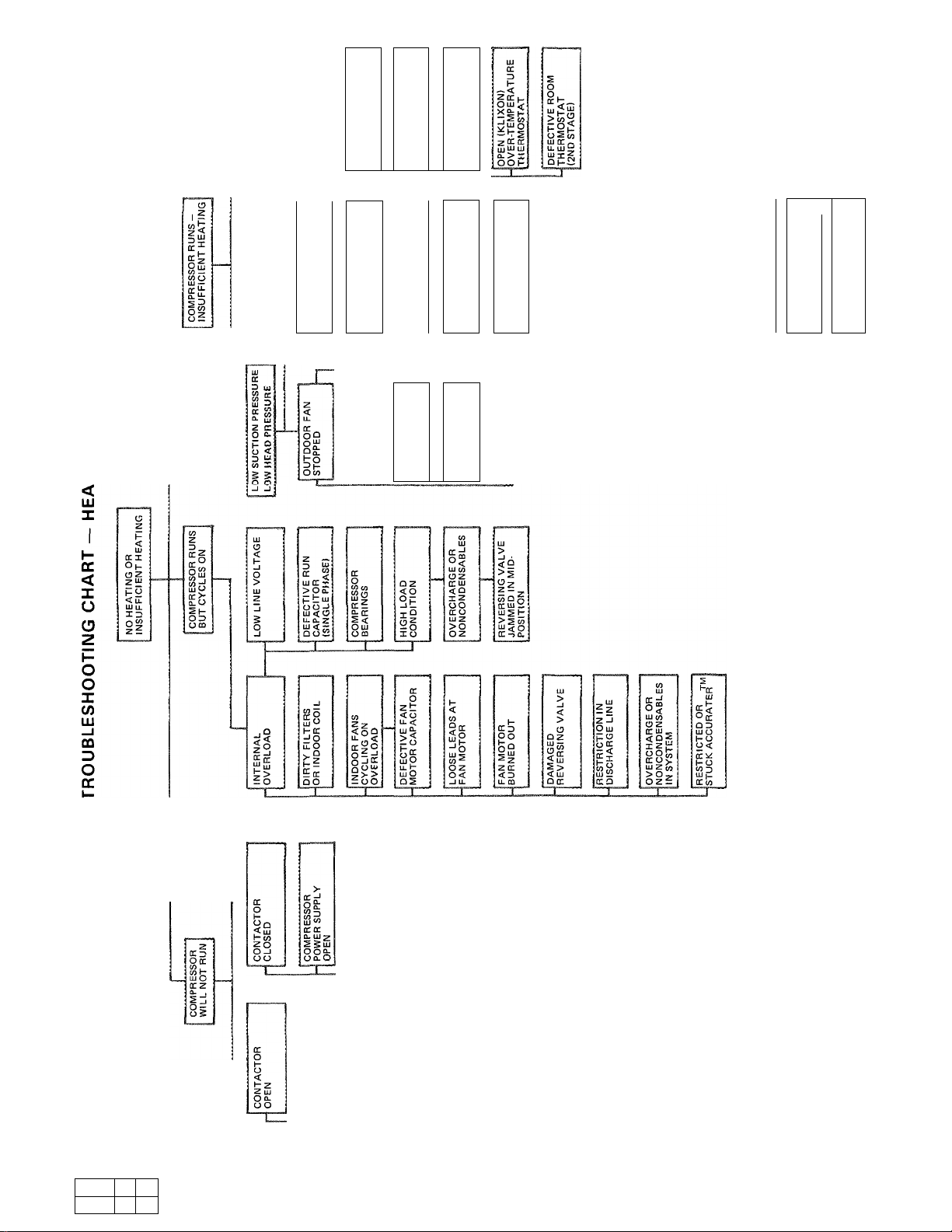
TROUBLESHOOTING CHART — COOLING CYCLE
#
Page 14
LU
o
>■
o
CD
tog
DC £
lij|_
b<
< CC
HI uj
X Q.
Q.O
<02
<o^
ljjy> I
ccOu-1
I— LU LU I
(0(00 I
Z
<
X
gg
o~
QZ
HZ
3D
OX X -i
X
Xiu
tUH
5<
OLU
X I
-h-i2
“t-z
2-uj
ZoS
LU ^ LU
X i _l
OGLU
O X
LUZ
EC2
H 3
(0/-1
III LU
Z
-J
to
3
X
z
g
o
-J
CO
5 CC
h OQ
ccqI^
LU S C5
HhO
<oo
oiSg
<0:9
<i
X X
_l -J
<x
Zq:
£°2
E50
X
H
<
LU
zz
LU LU
CQ LU
Q
X
(3
<
X
G
X
X
Q
Z
3
XD
oo
o°
2z
Z X
<3
X ffl
X
lLU H
X
3
to
X
f ^
X UJ
<o
Zx
X X
H^
5x
Ex
On
_l
lQ
X
Ov
H^
dE
OQ
ai
U. LU
LU I
OK
IL CC
0>(r
lu<E
U. U ¡c
LU LU £
OXh-
IW
!iJo
s?
[Xm
G CC
<|d
<
G?G
>
E^£
o
H<f G
z
^i=X
QGX
<XX'
XZ C
X
O
- E
a o
?cc
zm
LU 3
Q-O
O a.
(O CO
Q CO
<LU
Sec
“^5
wg
OK
_) <
LJ QJ
lU CC
>iuo
pou.
o <
lul-Z
Li. -i <
lUOX
Q>l-
k
So
O
o ^
Oi-
5
cc<
X
o
(O
to
LU
5d
ofe
5>
LU
(5 LL
Z LU
x>
LU <
> -I
8t
cc:?
Oco
Gqc
<o
Z LU
OQl
GO
X LU
LU>
X cu
QU-
LU
9q
2<
-JO
X
< xO
H. OZ
ZlunS
yccejo
Xh-XLU
X < LU X
OLUZ>
(OXLU&
So
X CC
Og
OJZ
X
o
X
<
For replacement items use Carrier Specified Parts
Manufacturer reserves the right to discontinue, or change at any time, specifications or designs without notice and without incurring obligations.
Book
1
Tab
5a
4
5a
Form 50QT-1OSI Supersedes 50QT-8SI
Printed in U S A
5-84
PC101 Catalog No 565-033
t
 Loading...