

Page 1
50QQ
#
HEATING A COOLING
Single-Package Heat Pumps
Installation, Start-Up and Service Instructions
CONTENTS
Page
SAFETY CONSIDERATION
INSTALLATION..................................................................1-7
Step 1—Check Equipment and Jobsite............................. 1
• UNPACK UNIT
• INSPECT EQUIPMENT
• COMPLETE SYSTEM REQUIREMENTS
Step 2—Mount Unit.............................................................. 2
• ON THE GROUND
• ON THE ROOF
Step 3—Make Ductwork Connections
• CONNECT RETURN AND SUPPLY AIR
DUCTWORK
Step 4—Provide for Cooling Cycle
Condensate Disposal
• CONNECT DRAIN LINE
Step 5—Make Electrical Connections
• INSTALL A BRANCH CIRCUIT DISCONNECT PER
NEC
• ROUTE LINE POWER LEADS INTO UNIT
• CONNECT GROUND LEAD TO GROUND LUG
• SET INDOOR FAN MOTOR SPEED
• ROUTE CONTROL POWER WIRES
• ACCESSORY DUCT FLANGE KIT INSTALLATION
• ELECTRIC HEATER INSTALLATION
START-UP
SERVICE...........................................................................8-15
............................................................................
SAFETY CONSIDERATIONS
Installing and servicing air conditioning equipment can be
hazardous due to system pressure and electrical compo
nents. Only treuned and qualified service personnel should
install or service air conditioning equipment.
Untrained personnel can perform basic maintenance func
tions such as cleaning coils and filters and replacing filters.
All other operations should be performed by trained service
personnel. When working on air conditioning equipment,
observe precautions in the literature and on tags and labels
attached to unit.
Follow all safety codes. Wear safety glasses and work
gloves. Use quenching cloth for brazing operations. Have
fire extinguisher available.
.................................................
...............................
......................................................
...............................
1
2
4
5
8
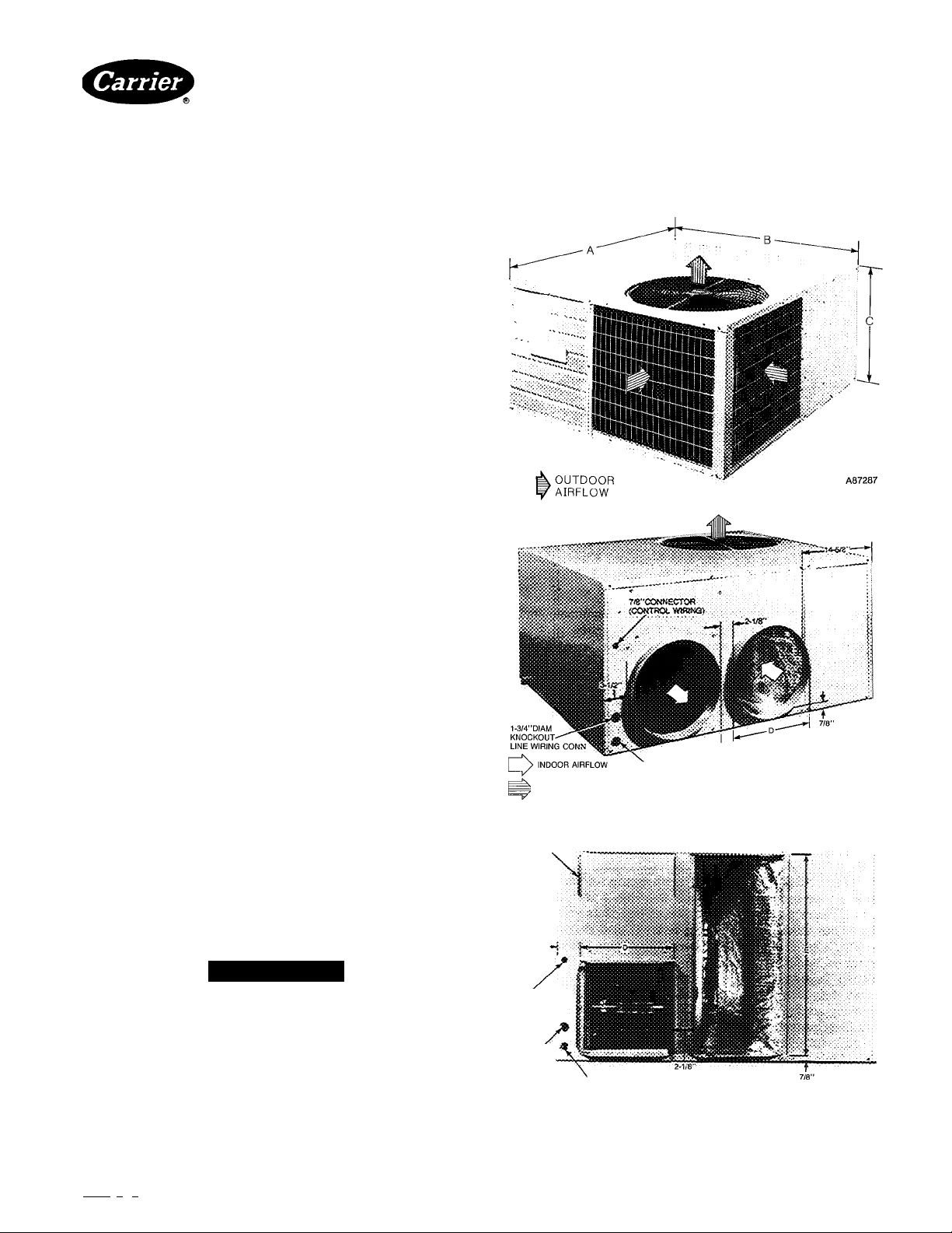
1-5/8” DIAM KNOCKOUT ELECTRIC HEAT
> OUTDOOR AIRFLOW
RIGHT-SIDE VIEW - MODEL 018 048(TYPICAL)
DUCT FLANGE
FOR 14”X28”
CONNECTION
A88061
A WARNING
Before performing service or maintenance operations on
7/8”
CONNECTOR^
system, turn off main power switches to unit. Turn off
accessory heater power switch if applicable. Electric
shock can cause personal injury.
INSTALLATION
Step 1—Check Equipment and Jobsite
1-3/8”DIAM
KNOCKOUT
LINE WIRING
CONN
RIGHT - SIDE VIEW • MODEL 060
1-5/8”DIAM KNOCKOUT
ELECTRIC HEAT
UNPACK UNIT—Move unit to final location. Lift off car
ton tEiking special care not to damage unit.
Manufacturer reserves the right to discontinue, or change at any time, specifications or designs without notice and without incurring obiigations.
Bookl 1 I 4 PC 101 Catalog No 565-097 Printed in USA Form 50QQ-8Si 11/87 Pg 1 Replaces: 50QQ-7Si
Tab i5a 15a
Fig. 1 —Dimensions and Connections
Page 2
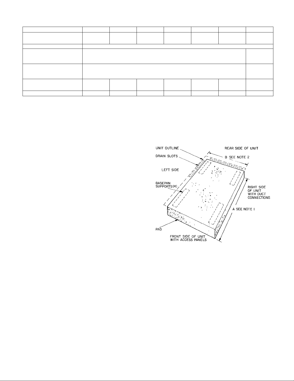
Table 1—Physical Data and bimensions
MODEL 50QQ
REFRIGERANT (R-22)
Operating Charge (lb)
Refrigerant Control
SHIPPING WEIGHT (lb) 323 1 329 1 346 1 357 | 402 | 445 | 484
DIMENSIONS (in.)
DUCT CONNECTIONS (in.)
FILTER SIZE (in.)t
Disposable
Permanent
*Dimension C includes %-in built-in base support channels
tOptional square duct flanges are available as an accessory for 14-in x 14-in duct.
ijiRecommended field-supplied filters are one-in. thick.
A
B
C*
D
E
018 024
7 lbs 4 oz
20x25 20x25 (2)15x20
15x20 15x20 20x20
6 lbs 8 oz 8 lbs 0 oz
22'k 1 2472 1 29% 32%
030
Side-By-Side
Round!
036
7 lbs 4 oz
Piston
48
14
15x20
20x20 (2) 20 X 20
20x25
8 lbs 2 oz
INSPECT EQUIPMENT—File claim with shipping com
pany if shipment is damaged or incomplete.
COMPLETE SYSTEM REQUIREMENTS before
installing.
Consult local building codes and National Electrical Code
(NEC) ANSI/NFPA 70-1987 for special installation
requirements.
Provide sufficient space for coil airflow clearance, wiring,
and servicing unit. See Fig. 1 and 2. Locate unit where sup
ply and return air ducts can be conveniently brought out to
unit duct connections.
Unit may be placed with duct side as close to building as
top removal, duct connections and power connections per
mit. Position unit so water or ice from roof does not drop
directly on top of unit or in front of coil. Make provisions for
condensate drainage and defrost water disposal. Maintain a
4-ft clearance above unit for vertical air discharge.
Roof installation method for 50QQ depends on building con
struction and special requirements of local building codes.
Ensure that roof can support unit weight. Protect unit from
prevailing winds to ensure adequate defrost.
Step 2—Mount Unit
NOTES:
1
In areas of snowfall or subfreezing temperatures when elevated
frame Is used Dimension A is 48-in., Dimension B is 42-in. In areas
where elevated frame is not used Dimension A is 45-in , Dimension
B is 39-in
Allow a 3-ft service clearance at front and rear sides of unit
ON THE GROUND—Mount heat pump on an elevated
frame positioned on a level pad. See Fig. 2 for pad dimen
Fig. 2—Pad Dimensions
sions. Ensure pad does not obstruct coil slots in unit basepan. (Slots drain water during heating and defrost cycles.
See Fig. 2 for drain slot locations.) Construct pad to provide
clearance under basepan coil slots for drainage and ice
buildup. In areas where prolonged subfreezing temperatures
or snowfall occur, increase clearance to 12 to 18-in. by con
structing an angle-iron frame to support unit 12 to 18-in. off
base. Design cross angle of frame so as not to obstruct basepan coil slots. See Fig. 3 for recommended frame construc
tion. Alternate construction should follow dimensions.
Extend a 24-in. gravel apron around pad for condensate and
defrost water drainage field.
ON THE ROOF—Mount unit on a level platform or frame.
Elevate unit for proper clearance as described under ground
insteJlation above. Design roof and plan water runoff so as
to prevent unit and its duct flashing from sitting in water,
in accordance with eJl applicable codes.
Step 3—Make Ductwork Connections
CONNECT RETURN AND SUPPLY AIR DUCT
WORK—Connect ductwork to unit supply and return air
duct connections. Refer to Fig. 1 and Table 1 for unit supply
and return air connection sizes and locations.
Flanges are provided on Models 018-048 for round duct con
nections, on Model 060 for rectanguleu- duct connections.
Accessory duct flange kit is available for squeire or rectan
gular connections on 018-048 units. Refer to accessory
Installation Instructions on page 5 for connections to
ductwork.
Fig. 4 shows a typical duct system with 50QQ installed. Do
not operate unit longer than 5 minutes without ductwork or
damage to blower motor may result.
042
20x25
048
9 lbs 0 oz
20x25
20x20
(2) 15x 20 (2) 20 X 20
060
9 lbs 0 oz
Side-By-Side
Rectangular
13"/,eXl3’7,e
13"Ae X 277a
25x25
20x25
A88063
Page 3
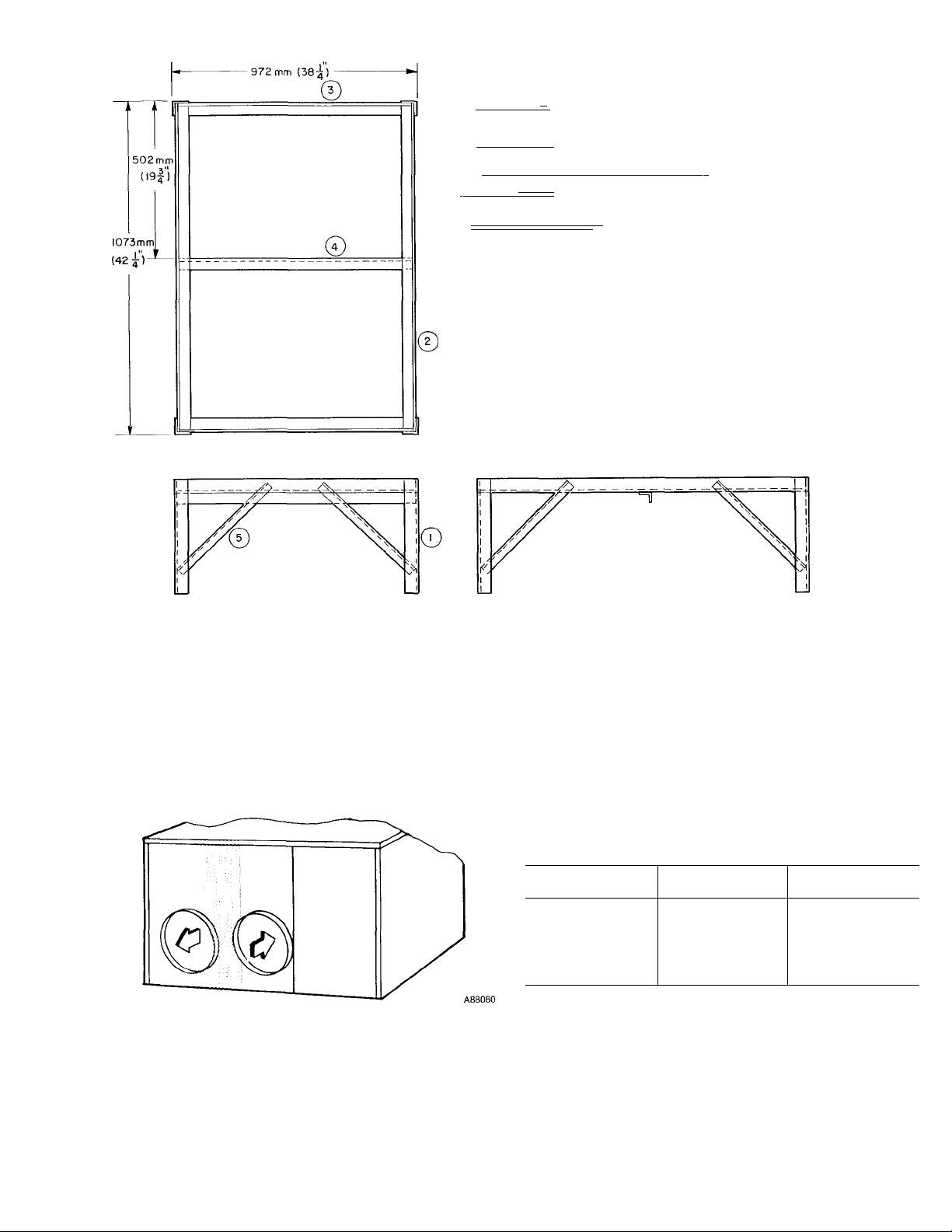
I =\ = = = ^ 305 mm (12") TO 610 mm (24") (4) REQ
I
^ ----- —---------------------------------------------------------------------'(411") (2) REQ
' I ---------------1 I 959mm (37|")(2)REQ
^ I
----------------------
gj I I - |-^ 406 mm (16") (8) REQ
material:
ANGLE IR0N-3L8mm(l^) TO 38mm (1^) COMM'L STD
WELD FRAME TOGETHER
PAINT WITH ZINC-RICH PAINT (RUSTPROOF)
-| 959mm(375 )(l) REQ.
r 38 mm (1-5) 3"
#
Fig. 3—Heat Pump Mounting Frame
When designing and installing ductwork, consider the
following:
1. When connecting ductwork to 042, 048 and 060 units,
do not drill deeper than one inch in shaded area shown
below. Coil may be damaged.
2.
Install field-supplied filters in return air ductwork. Rec
ommended sizes for filters are shown in Table 1.
3.
Avoid abrupt duct size increases and reductions.
Abrupt change in duct size adversely affects air
performance.
4.
Use flexible connectors between ductwork and unit to
prevent transmission of vibration. When electric heater
is installed, use fireproof canvas (or similar heat resis
tant material) connector between ductwork and unit
discharge connection. If flexible duct is used, insert a
sheet metal sleeve inside duct. Heat resistant duct con
nector (or sheet meted sleeve) must extend 24-in. from
electric heat element.
5. Size ductwork for cooling air quantity (cfm). The mini
mum air quantity for proper electric heater operation is
listed below. Heater limit switches may trip at air
quantities below those recommended.
MODEL
50QQ
018
024
030
036
042
048
060
INDOOR FAN
SPEED SETTING
Low 1400
MIN CFM
675
875
875
1400
1700
1800
6. Insulate and weatherproof all external ductwork. Insu
late and cover with a vapor barrier all ductwork pass
ing through unconditioned spaces. Follow latest
SMACNA (Sheet Metal and Air Conditioning Contrac
tors National Association) minimum installation stand
ards for residential heating and air conditioning
systems.
7. Secure all ducts to building structure. Weatherproof
duct openings in wall or roof according to good con
struction practices.
Page 4
PARAT NO.
99TZ900521
99T2900571
50LQ90002106
50LQ90001106
38RQ900012
50LQ90000106 Outdoor Thermostat (Six 50LQ900001)
50LQ900031
32LT900301
32LT900611
50YM900051
88EM0050MA01
88EM0075MA01
88EM0100MA01
88EM0150MA01
88EM0200MA01
88EM0250MA01
88EM0100EA01
88EM0150EA01
88EM0200EA01
88EM0250EA01
88EM0100FA01
88EM0150FA01
88EM0200FA01
88EM0250FA01
HC95DE023
HC95DD058
HC95DE088
HC95DE208
HN61HB510
HN61KB021
HN61KB075
♦Available through Service Parts
NOTE: Electric heaters are rated at 240 and 480 volts
Thermostat 1 -stage cooling, automatic changeover
Subbase 2-stage heating, Carrier, Honeywell
Thermostat 2-stage cooling, manual changeover
Subbase 2-stage heating, Carrier, Honeywell
Solid-State Time Guard® Control (Six 50LQ900021)
Service Sentry (Six 50LQ900011)
Supplemental Heat Relay—Used with 25 kW heater and 2 outdoor thermostats
Reversible Filter Drier and AccuRater Assembly
Motormaster® Head Pressure Control
Motormaster Head Pressure Control
Duct Flange Kit
Electric Heater—5 kW, 240-1
Electric Heater—7.5 kW, 240-1
Electric Heater—10 kW, 240-1
Electric Heater—15 kW, 240-1
Electric Heater—20 kW, 240-1
Electric Heater—25 kW, 240-1
Electric Heater—10 kW, 240-3
Electric Heater—15 kW, 240-3
Electric Heater—20 kW, 240-3
Electric Heater—25 kW, 240-3
Electric Heater—10 kW, 480-3
Electric Heater—15 kW, 480-3
Electric Heater—20 kW, 480-3
Electric Heater—25 kW, 480-3
Start Capacitor^
Start Capacitor^
Start Capacitor^
Start Capacitor^
Start Relays
Start Relays
Start Relays
Table 2—Accessories
DESCRIPTION
MODEL
50QQ
All
All
All
All
060
All
All
All 208/230-v
All 460-v
018-048
All
All
All
030-060
036-060
060
030-060
030-060
042-060
060
036-060
036-060
036-060
060
018
024, 030
036-048
060
018
024-048
060
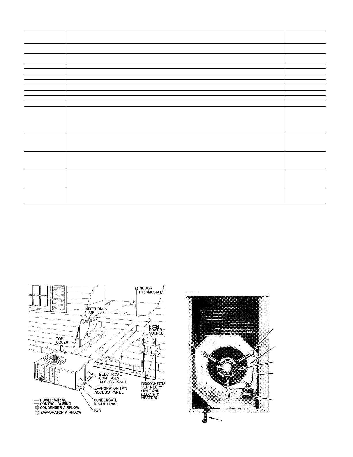
Step 4—Provide for Cooling Cycle condensate Disposal-
Condensate may be drained directly onto gravel apron or
connected by drain line(s) to a dry well. Follow local codes.
CONNECT DRAIN LINE to rubber condensate drain fit
ting on side of unit (see Fig. 5). Use clamp provided. Install
factory-supplied condensate trap (taped to indoor fan com
partment for shipment) at end of dredn line. If a drain line is
not used, connect condensate trap to unit drain fitting as
shown in Fig. 4.
FAN MOTOR
MOUNTING BOLTS
ORIFICE RING
FAN MOTOR
BLOWER
HOUSING
CAPACITOR
♦Separate disconnect per NEC required for electric heater
Fig. 4—Typical Installation
CONDENSATE TRAP
Fig. 5—Condensate Drain and Trap Details
Page 5
m
step 5—Make Electrical Connections—Install field wiring
in compliance with loced and national fire, safety and electri
cal codes. Be sure voltage to unit is within ± 10% of volt
age indicated on nameplate. Contact local power company
for correction of improper line voltage.
Operation of unit on improper line voltage constitutes
abuse and may cause unit damage that could affect war
ranty.
See Table 3 for recommended fuse sizes.
INSTALL A BRANCH CIRCUIT DISCONNECT PER
NEC of adequate size to handle unit starting current. Pro
vide a separate disconnect for unit and for each accessory
electric heater circuit as required. (See electric heater Instal
lation, Start-Up and Service Instructions.) Locate disconnect(s) within sight from and readily accessible from the
unit, per Section 440-14 of National Electriced Code (NEC).
ROUTE LINE POWER LEADS INTO UNIT-Extend
leads from disconnect per NEC through hole provided
(Fig. 1) into line wiring splice box. Use copper wire only.
CONNECT GROUND LEAD TO GROUND LUG in splice
box for safety. Connect power wiring. See Fig. 7. Connect
line power leads to yellow and black pigtails on single-phase
units.
SET INDOOR FAN MOTOR SPEED-Refer to page 3 for
minimum edlowable eiir quantity for safe electric heater
operation. Indoor fan motor is factory wired for low-speed
operation on all models. Fan motor is equipped with spadetype speed selector terminals marked 1, 2 and 3 on 3-speed
motors (042 and 048), and 1 and 2 on 2-speed motors (018,
024, 030, 036 and 060).
For electric heater operation, set motor at: LOW—sizes 018
through 042, and 060; MED—size 048.
MOTOR TERMINAL
FAN SPEED
(3-speed, 042, 048)
FAN SPEED
(2-Speed, 018-036, 060)
1
High
High
2
Medium
Low
3
Low
—
For air delivery performeuice, refer to Table 4.
ROUTE CONTROL POWER WIRES (24v) through 78-in.
connector provided in unit. Fig. 1. Extend leads to unit con
trol wiring terminal boeu-d in unit control box. Fig. 6. Con
nect leads to terminal board as shown in Fig. 8.
The unit transformer supplies 24-v power for complete sys
tem including accessory electric heater. A resettable circuit
breaker is provided in the 24-v circuit.
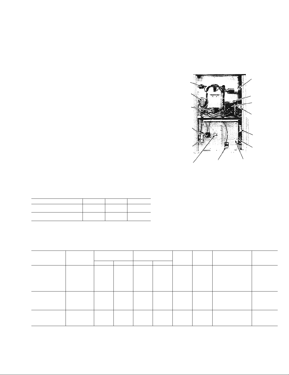
RUN
HEATER
CAPACITOR
CONTROL
VOLTAGE
CIRCUIT
BREAKER
CONTROL
BOARD
SUPPLE
MENTAL
HEAT
RELAY
SERVICE
SENTRY
UNIT
GROUNDING
LUG
START
THERMISTOR
TRANSFORMER
CONTACTOR
HEATER
CONTROL RELAY
TIME GUARD
LIM^i7cONTROL S^PLT^AGE GROUNDING
HEATER
connection
Fig. 6—Control Section
ACCESSORY DUCT FLANGE KIT INSTALLATION018-048
1. Refer to Fig. 8 for duct adapter dimensions and hole
locations.
2. Mark hole locations.
MODEL
5000
018
024
030
036
042
048
060
030
036
042
048
060
036
042
048
060
FLA —Full Load Amps
HACR—Heating, Air Conditioning, Refrigeration
IFM —indoor Fan Motor
LRA —Locked Rotor Amps
MCA —Minimum Circuit Amps
OFM —Outdoor Fan Motor
RLA —Rated Load Amps
V-PH
208/230-1 253 187 82 0
208/230-3 253 187 79 5
460-3
Max Min LRA
506 414 398
Table 3—Unit Electrical Data (60 Hz)
OPER
VOLTAGE*
COMPRESSOR
r RLA
50 0
53.0
65.0
106.0
1100
178.0
53 0
67 5
90.0
124.0
33.8
45 0
62.0
9.3 3.5 1 4
11 6 35
13.9
17.2
20 7 35
22.4 4.6 2.2
30.2 6.7
81
108
12.0
146 4.6
20.5 6.7
5.0
63 20
7.0 20
10.3
*Permissibie limits of the voltage range at which units will operate
satisfactorily.
tMaximum dual element fuse
NOTE: Use copper wire only.
IFM
FLA
35 1.4
35 22
35
35
46
1 7
3.4
OFM
FLA
1.4
22
2.8
1 4
2.2
2.2
22
2.8
07
1.3
1.3
1.3
MAX FUSEt
OR HACR CKT
BKR AMPS
25
30
35
40
50
50
60
20
25
30
35
45
15
15
15
25
MCA
165
19.4
22.2
27 2
31.6
34.8
47.3
15.0
19 2
21.8
25 0
35.1
8.7
11 2
12.1
17.6
Page 6

Table 4—Air Delivery (Cfm) Performance
MODEL
50QQ
018-10
024-10
030-
10&30
036-
10&30
042-10
042-30 230,
048-
10&30
060-
10&30
NOTES:
1. Air delivery values are based on 230- or 460-volt unit operating voltage without air filter or optional electric heaters Deduct field-supplied air filter and
electric heater pressure drop to obtain external static pressure available for ducting
2 Dashes indicate portions of table that are beyond blower motor capability,
3 Do not operate unit at a cooling airflow less than 350 cfm for each 12,000 Btuh of rated cooling capacity. Indoor coil icing may occur at airflows below
this point
UNIT
VOLTAGE
230 Wet
230
230
230,
460
460
230,
460
BLOWER
MOTOR
SPEED
Low Dry
High Dry
Low
High
Low Dry
High Dry
Low Dry
High
Low Dry 1850
Med
High
Low Dry 2395
High
COIL
Wet
Dry 1450
Wet 1390
Dry 1500
1460 1405 1350
Wet
Wet
Wet
Wet
Dry
Wet
Wet 1820
Dry 1960
1895 1880 1850 1795
Wet
Dry 2230
Wet 2145
Wet 2375
Dry 2570 2525 2470
Wet 2550
0.1 0.2 0.3
0.0
___
—
_
—
—
_
—
1410 1375
1340 1290 1225
1475
___ ___
— —
___ ___
_
—
__
___
—
___ ___
_
—
1810 1770 1725
1775 1730 1695
1915 1885 1830
2160
2105 2060 2000 1940
2365 2335 2290 2245
2325
2485
1435
1425 1360
1380
1500
1450
1440 1400
1400 1365 1290
1500
1465 1430
2120
2295
2435 2385
EXTERNAL STATIC PRESSURE (in. wc)
___ ___
—
— —
—
1320 1345 1175
1390 1335
1295 1255 1190
1315
1425 1245
1375 1295 1230
1460 1410
2070 2010
2250 2225
2425 2370
0.4 0.5 0.6
—
—
—
— 750 680
—
— 785 685
1165 1105
1295 1235
1250 1190 1125
1345 1290
1365
1685
1650
1780 1725
1745 1690
2345
800
820 680
1260 1180
1275 1190
1240
1345
1300
1640 1600
1610 1555
1950
1880 1820
2205
2180
2335 2265
2310 2235
0.7
640
730
550
550
575
1090
1020 915 740
1110
1160 1080
1145
1225
1185
1270
1230 1145 1020
1655
1620 1565 1510
1890 1820 1750 1675
2150 2100 2050
2135 2070 2020
985
1090 980
1020 870
1045 960
1120 1020
1080 985
1140 1040
1090 990
1195 1075
1535 1480
1500 1440 1385
1600
1750 1690 1615
2220 2160 2100
2190
1540
2130
0.9
0.8
_
—
— — —
— —
— —
760
850
_
840
—
995 925
895 790
935
905
930
890
930
890 —
1410
1470
1445
2000 1915
1960 1875
2075
1.0
—
_
—
—
815
830
805
—
—
—
1345
1320
1400
1375
1590
1540
2030
2000
3. Using duct flange as a template, make sure marked
locations line up with clearance holes on flanges.
4. At marked locations, drill screw engagement holes
using a #26 (.147-in.) twist drill.
GROUND LUG
(IN SPLICE BOX)
--GROUND LEAD
I - PHASE
CONN.
TO
DISCONNECT
PER NEC
3-PHASE
CONN.
TO
DISCONNECT
PER NEC
L2
L2
L3
__________
__________
- - GROUND LEAD -
----------------------
BLK
^
YEL
HEAT PUMP
GROUND LUG
(IN SPLICE BOX)
BLK
■BLU
-5^YEL - -s
HEAT PUMP
--------
--------
--------
A CAUTION
On 042, 048, do not drill deeper than one inch in shaded
area. Damage to refrigerant coil could result.
5. Attach duct adapters using #10B, V2-in. long screws
supplied in accessory kit.
6. Finished kit installation accommodates a 14-in. x 14-in
duct.
1
S
5
Fig. 8—Duct Fiange Kit Dimensions and Hoie Locations
A88058
#
Fig. 7—Line Power Connections
A88059
ELECTRIC HEATER INSTALLATION-For complete
heater installation data, refer to separate accessory electric
heater Installation, Start-Up and Service Instructions.
Page 7

THERMOSTAT
8 SUBBASE
(SEE BELOW)
0-
&
UNIT
CONTROL WIRING
TERMINAL BOARD
THERMOSTAT
a SUBBASE
UNIT
CONTROL WIRING
TERMINAL BOARD
B-
0
-
0
-
0
-
COOLING AND ONE-STAGE HEATING
THERMOSTAT
a SUBBASE
(without Electric Heater)
UNIT
CONTROL WIRING
TERMINAL BOARD
0)
<g>
^0
-0)
ODT—Outdoor Thermostat Assose
HR —Heater Relay
(Unit equipped with Eiectric Heater, Suppiemental Heat,
THERMOSTAT
a SUBBASE
COOLING AND TWO-STAGE HEATING
One Outdoor Thermostat)
UNIT
CONTROL WIRING
TERMINAL BOARD
(Unit equipped with Electric Heater, Supplemental Heat,
COOLING AND TWO-STAGE HEATING
No Outdoor Thermostats)
Fig. 9—Control Connections
SHR—Supplemental Heat Relay
HR —Heater Relay
ODT—Outdoor Thermostat
COOLING AND TWO-STAGE HEATING
(Unit equipped with Eiectric Heater, Supplemental
Heat Relay, Two Outdoor Thermostats)
A88054
Page 8

START-UP
The 50QQ unit compressors Eire equipped with crankcase
heaters. It is recommended that heater be energized a mini
mum of 24 hours before starting unit. To energize heater
only, set thermostat at OFF position; turn on unit main
power at disconnect switch.
Heat Anticipator Settings for Room Thermostat—Set
anticipator settings for room thermostat according to sepa
rate accessory electric heater Instedlation Instructions.
Accessory Outdoor Thermostat provides adjustable out
door control of accessory electric heaters of 15 kW and
leirger. This thermostat makes contact when a drop in out
door temperature occurs. It energizes a stage of electric
heat when the outdoor temperature setting is reached, pro
vided the room thermostat is on the second stage of heat
ing. An outdoor thermostat is recommended for the second
stage of electric heat. Refer to heat load of building and unit
capacity to determine the correct outdoor thermostat
setting.
The accessory supplemental heat relay is required when 2
outdoor thermostats are used. It is automaticeilly energized
by the manually operated supplementeil heat switch in the
indoor thermostat subbase. The indoor thermostat locks out
compressor and the relay bypasses the outdoor thermostats
for electric heater operation during heat pump shutdown.
When one outdoor thermostat is used, a supplemental heat
relay is not required. The supplemental heat switch in the
indoor thermostat subbase bypasses outdoor thermostat,
locks out compressor and activates electric heater.
MOUNT OUTDOOR THERMOSTAT-Locate maximum
of 2 outdoor thermostats in the controls section on the cen
ter post to the left of the electric heater. Fasten with screws
in holes provided. Route capillary tube per instructions in
thermostat package.
MOUNT SUPPLEMENTAL HEAT RELAY in low-voltage
section of control box to right of low-voltage connections,
using holes provided.
To Start Unit—Check that main power is on and that com
pressor crankcase heater has been energized for at least 24
hours.
1. Check that heater main power is on as applicable.
2. Set selector switch at OFF.
3. Set fan switch as desired (FAN) (AUTO.).
4. Set thermostat died at the desired temperature.
5. Set selector switch at HEAT or COOL. Check system
refrigerant charge as described under Service.
Unit Single-Phase Compressors are Equipped with a Com
pressor Start Thermistor (PTC device)—When supply volt
age is within 10% limit and compressor does not start,
check the start thermistor with an ohmmeter.
CHECKING START THERMISTOR
1. Shut off all power to unit and wait 10 minutes for
thermistor to cool to ambient temperature.
2. Remove thermistor from circuit.
3. Measure resistance of thermistor with ohmmeter. Nor
mal resistance readings are 25 ohms ± 20% at 75 F
ambient temperature.
4. If ohmmeter resistance reading is not within ± 20%,
the thermistor is defective and must be replaced.
If start thermistor is good and compressor does not start,
disconnect the thermistor from starting circuit and give
compressor a temporary capacitance boost. Run compressor
for 10 minutes, then shut off and eillow system pressure to
equalize. Reconnect start thermistor and try restarting
compressor without boost capacitor. If after 2 attempts the
compressor does not start, remove thermistor and add an
accessory start capacitor and relay.
SERVICE
A WARNING
Before installing or servicing unit, turn off main power
to system. There may be more than one disconnect
switch. Turn off accessory heater power if applicable.
Electrical shock can cause personal injury or death.
Unit Controls and Safety Devices
The following controls are used on all units:
HIGH-PRESSURE RELIEF VALVE (Safety Control) is
located in compressor. Relief valve opens at a pressure dif
ferential of approximately 450 psi between suction (low
side) and discharge (high side) to allow pressure
equalization.
INTERNAL CURRENT AND TEMPERATURE SENSI
TIVE OVERLOAD (Safety Control) resets automatically
when internal compressor motor temperature drops to a
safe level. When an internal overload is suspected of being
open, check by using an ohmmeter or continuity tester.
DEFROST CONTROL, consisting of a control board and
defrost thermostat, interrupts normeJ system heating oper
ation to remove frost and ice formation on outdoor coil.
Frost impairs unit performance. Defrost control simulta
neously stops outdoor fan, energizes reversing valve sole
noid to switch system into cooling cycle (outdoor unit as
condenser, indoor unit as evaporator), and activates acces
sory electric heater. Unit can defrost every 90 minutes, but
will do so only if outdoor temperatures are in the frosting
temperature zone.
For heat pump to defrost, 2 conditions are necessary:
1. Defrost timer contacts must be closed.
2. Refrigerant temperature must be cold enough to cause
defrost thermostat contacts to close. Contacts close at
27 ± 5 F.
Every 90 minutes of elapsed running time, the defrost timer
contacts close for 10 seconds. If the defrost thermostat con
tacts are closed, the unit defrosts. The defrost timer limits
defrosting period to 10 minutes. Normally the frost is
removed and the defrost thermostat contacts will open to
terminate defrosting before 10 minutes have elapsed.
Defrost thermostat contacts open at 80 ± 6 F. When
defrosting is terminated, the outdoor fan motor is energized
and reversing valve solenoid is de-energized, returning unit
to heating cycle.
The 90-minute period to check for defrost can be changed to
50 or 30 minutes by moving a jumper wire on the defrost
printed-circuit board.
HEAT PUMP CIRCUITS shown in Fig. 10 are refrigerant
flow diagrams for heating and cooling cycles.
Refrigerant Charging
A WARNING
Avoid contact with hot gas discharge line to prevent a
burn when working on compressor.
Page 9

COOLING STRAINERS HEATING
©
INDOOR
FAN
COOLING STRAINERS HEATING
Fig. 10—Refrigerant Flow Diagrams
Table 5—Service Data
MODEL 50QQ
R-22 CHARGE* (lb) 7 lbs 4 oz 6 lbs 8 oz 8 lbs 0 oz 7 lbs 4 oz
Piston Htg/cig.
INDOOR FAN
Rpm
Diameter (in.)
Width (in.)
Range (cfm)
Motor Hp
OUTDOOR FAN
Cfm
Rpm
Diameter (in.)
Motor Hp
•'Factory refrigerant charge
018
52/42
10
6
525-750 700-1000 875-1250
Va
2200
840
22
%
A WARNING
To prevent personal injury, wear safety glasses and
gloves when handling refrigerant.
Do not overcharge system. An overcharge can cause
compressor flooding.
024 030
61/49
840
Va
2200
840
22
67/32 76/63 78/70
2200
Centrifugal—Direct Drive
'h %
Propeller—Direct Drive
840 1100 1100
22 22
Vs
mode when temperature is below 65 F. If charge must be
checked in opposite mode, do not operate unit continually
for more them 10 minutes or damage to compressor may
result.
Refrigerant system is fully charged with R-22 refrigerant,
tested, and factory sealed. For more applications, factory
036
840 1100
1020-1450 1170-1670 1340-1920 1690-2420
2700 3200
74 74 74 V2
cheu-ge is the correct Eimount for best performance; however,
this charge may require a slight adjustment to atteun rated
performance.
Unit refrigerant system is factory charged. When recharg
ing is necessary, weigh in total charge indicated in Table 5.
NOTE: Adjustment of refrigeremt cheu-ge is not required
unless unit is suspected of not having proper R-22 charge.
(Charge must be weighed in during heating season.) Remove
any refrigerant remaining in system before recharging. If
system has lost complete charge, evacuate system to 5000
microns (29.7-in. vacuum) before recharging. Schrader fit
ting connections are provided on unit suction and discharge
lines for evacuation and charging. (See Fig. 12 for Schrader
fitting location.) Volumetric charging device is an accurate
device used to recharge systems by weight. These cylinders
When evaluating refrigerant charge, an indicated
adjustment to specified factory charge must always be
very minimal. If a substantial adjustment is indicated,
an abnormal condition exists somewhere in system,
such as insufficient airflow across either or both coils.
are available at refrigeration supply firms.
CHARGING AND ADJUSTING REFRIGERANT
CHARGE
NOTE: Check refrigerant charge in cooling mode when out
door temperature is above 65 F. Check charge in heating
Heating Mode
1. Remove gage port caps from both service valves and
attach gage manifold. Use hoses with valve core
depressors.
COOLING CYCLE
042
8 lbs 12 oz 9 lbs 0 oz 9 lbs 0 oz
12
6
V2
22 22 22
048
82/73 93/84
72
3200 3400
1100 1100
A CAUTION
A87291
060
1100
%
Page 10

Table 6—Field Charging Table—Fixed Restrictor
HEATING OPERATING PRESSURES PSIG (Pressures at High and Low Side Service Ports)
MODEL
50QQ
018
024
030
036
042
048
060
NOTE: Add charge if pressures are low Bleed out charge if pressures are high. Allow ± 5 psig tolerance on high-side pressure.
INDOOR
DRY BULB (F) 60
65 High 217
70 High
75 High 248 232
65
70
75 High 251 235
65 High 219 203
70 High 235 219
75 High 250 235
65 High 218 202
70 High 231 216
75
65 High 212 197
70 High 226 211
75 High 241 225
65 High 315 200
70 High 229 213 200 187
75 High 243
65
70 High 228 213
75 High 243
Low 77.2 65
Low
Low 78.4 65.9
High 219
Low 72.1
High 235
Low
Low
Low 70.5 58.9
Low 71.1
Low 71.5 59.9
Low 70.9 59.1
Low 71.4 59.6 49.3
High 246
Low 72 60.1
Low 69.6 58.1
Low
Low 70.7 59.2
Low 67.7 56.5
Low
Low 69
High 214 199 185 174 163
Low
Low 65.8 54.8
Low 66.4 55.4
232 217 203 192
77.8 65.4
72.6 60.9
73.2 61.4 51 41.6
70.2 58.7 48.6 39.7 31.9
68.3 57.1
65.2 54.2
OUTDOOR TEMPERATURE (F) DRY BULB
50 40
202 189
204 191 179
60.4 50.2 40.8 32.5
219
53.8 43.7 34.7
54.2 44 35
218
54.9
205
50.5
221 209 196
190 179 168
48.7
205
59.4
49.2
222
49.7
190
48.8
202
230 216
227 213
57.7 47.7 39 31.4 24.3 18.1
227 213
49.7 40.5 32.5
184
48
197
211
49.1 40.2 32.3
186
46.7 38.1 30.5
47.2
44.7
199
45.2
45.7
30
178
205
44.4
194
41.2
39.8
195
40.2
208
40.6
180
39.8
192 186
40.1 32.2 24.9
205
172
39.2
185
198
174
38.6
200
36.4 29
187
36.9
200
37.3
20
168
181
195
35.2 27.3
171 161
183
32.9
33.2 25.6
31.9
184 170
32.2 24.9
196
32.5
172 161
31.9 24.6
198
162
31.5
174
187
163 154
175 164
31 24 17.8
189 177
175
29.5 22.9
189 178
29.9 23.2
10
157
26.8
169 158
27 19.8
184 174
25.1
174 164
25.4 18.7
185
153 150
24.7
186 176
25.2 18.6
174
187
25.2
153
24.4 18
164 155 145
24.7 18.3 11.8
176 165
25 18.5
23.7 17.5 11.3
155 145
22.5 16.6
164 155 146
0
149 140
19.7 12.6
21.1
150
18.4
176 165
18.9
18.1 11.6
158
18.3
152
18.1
163 153
18.3 11.7
178 169
18.5 11.9
144 135
145 136
154 144
167 156
16.8 10.8
168 158
17.1 11.0
-10
147
12.9
165
13.2
139
11.7
154
12
12.1
141
145
11.7
167
11.9
142
11.6
11.6
155
12.1
11.5
11.8
136
10.8
COOLING DESIRED SUPERHEAT TEMP (F)
B
OUTDOOR
DBT
DGT(F) 54
60
65
70 7
75
60
85
90
95
100
105
110
115
*Do not attempt to charge system under these conditions or refrigerant
slugging may occur
NOTE: Add charge if actual superheat temperature is higher than chart
value. Remove if lower Allow ± 3 F for tolerance.
Unit is factory charged with R-22 in accordance with amount shown
on rating plate. This chart is intended for usage when minor unit
charge adjustments are required. For large charge adjustments, evac
uate unit and weigh in charge according to unit rating plate. Best per
formance will be achieved when unit operates with a suction gas
superheat at compressor inlet of 5 F at normal rating conditions of
Air Conditioning and Refrigeration Institute (ARI). This chart may be
used to approximate the charge if ARI rating conditions cannot be
obtained. ARI rating conditions are 95 F db outdoor. 89 F and 67 F
wb indoor. See Table 4 for required indoor airflow rates. Charge unit
with outdoor fan operating only on high speed.
12 15 18
10 13 16 19 21
if
*
■¥
* * *
♦
♦
♦
«
*
(Measured at Low-Side Service Port)
EVAPORATOR AIR INLET WBT (F)
56
58
60 62
21 24 27
10 13
6 9
*
*
* *
* «
* ♦
* *
♦ *
16
12
5 8 12
*
«
*
* *
*
* * ♦
« * * *
«
64
24 27 30
21 24 27
19
18 21 24
15
15
11
8
5
*
*
66 68 70
30
18
15
9
13
6
10
*
* * *
33
21
19 22 26
16
14
12
8
9
5
6
72
38 40 43
36
36
33
33
30
31 34 37
28
28 31 35
25
24
20
22
18
15 20 23
17
13
11 15 20
14
8
74
38
36
30
27 31
25
22 26
18
76
41
39
33
29
27
25
23
REQUIRED SUCTION TUBE (F) VS. DESIRED
(Measured at Low-Side Service Port)
DESIRED
SUPERHEAT
TEMP (F)
0 35
2 37
4 39
6 41
8
10
12 47
14 49
16 51
18
20
22 57
24 59
26 61
28 63
30
32 67
34 69
36 71
38
40
NOTE: Measure suction tube (F) with accurate superheat thermocouple
or thermistor-type thermometer.
FINAL DISPOSAL: CAUTION—CAREFULLY RELIEVE REFRIGERANT
PRESSURE WITHIN UNIT BEFORE FINAL DISPOSAL
SUCTION OR LOW-SIDE PRESSURE (psig)
61.5 64.2
37
39 43 43 45 47
41 43 45 47 49 51
43 45 47 49 51
45 47
43
47 49 51 53 55
45
49 51
51 53
53 55
53 55 57
57
55
59 61
61 63 65 67 69 71 73 75
63
65 67
67 69 71 73
65
69 71
71 73 75 77 79 81 83 85
73 75 77 79 81
75 77
73
77
75
SUPERHEAT (F)
AT SERVICE PORT
67.1
39
59 61 63 65
65 67 69 71 73 75
79
73
70
41
43 45
49 51 53
55 57
53
57 59
55
59
57
61 63
59
65 67 69
63
71
69
75
73
81 83 85 87 89
79
81 83
76
61
73
75
77
85
79.2 82.4
47 49 51
49
53
55 57 59
57
59
61
63
65 67
67
75 77
77 79 81
79
83
87 89 91
85.7
51 53
53
55
59
61 63
63 65
65
69
71
81
85
55
57
61
67
69
71
73
77
79
83
87
10
Page 11

2. Start unit and allow to operate until operating condi
tions stabilize and pressures level out.
3. Evaluate system performance and refrigerant charge
level by determining following conditions:
a. High- and low-side pressure gage reading.
b. Dry-bulb temperature of inlet air at outdoor coil.
c. Dry-bulb temperature of inlet air at indoor coil. This
may be read at central return-eiir grille.
d. Compare readings to those listed in Heating Operat
ing Pressures section of charging chart inside unit
(refer to Table 6, part A). The Heating Operating
Pressures portion of the chart is for checking charge
only when unit is in heating mode and outside tem
peratures are below 60 F.
If charge adjustment is necessary, charge can be adjusted
accurately only by blowing the charge, evacuating system,
and recharging unit with correct charge as listed on unit rat
ing plate. A volumetric charging device such as Dial-acharge is recommended for use when recharging.
Cooling Mode—A superheat charging label is affixed to elec
trical access door. The label includes a Field Superheat
Charging table (see Table 6, peirt B) and a Required Suction
Tube Temperature (F) chart (see Table 6, part C).
An accurate superheat-, thermocouple-, or thermistor-type
thermometer, a sling psychrometer, and a gage manifold are
required when using superheat charging method for evalu
ating unit charge. Do not use mercury or small dial-type
thermometers. They are not adequate for this type of
measurement.
Proceed as follows:
1. Remove caps from low- and high-pressure service
fittings.
Using hoses with valve core depressors, attach low-and
2.
high-pressure gage hoses to low- and high-pressure
service fittings, respectively.
Start unit in cooling mode. Let unit run until system
3.
pressures stabilize.
Measure and record following;
4.
Outdoor ambient air dry-bulb temperature (F).
a.
Evaporator inlet air wet-bulb temperature (F).
b.
Suction tube temperature (F) at low side service
fitting.
Suction (low side) pressure (psig).
d.
Using Field Superheat Charging table, compare out
5.
door air dry-bulb temperature (F) with evaporator inlet
air wet-bulb temperature (F) to determine desired sys
tem operating superheat temperature.
Using Required Suction Tube table, compare desired
6.
superheat temperature (F) with suction (low side) oper
ating pressure (psig) to determine proper suction tube
temperature.
Compare actueil suction tube temperature with proper
7.
suction tube temperature. Using a tolerance of ± 3 F,
add refrigerant if actual temperature is more than 3 F
higher than proper suction tube temperature, or
remove refrigerant if actueJ temperature is more than 3
F lower than required suction tube temperature.
Metering Device (Dual-Piston Type) Servicing—See Fig. 11
for dual-piston components. The pistons have a refrigerant
metering orifice through them. The retainers form a stop for
the pistons in the refrigerant bypass mode, and a sealing
surface for liquid line flare connection. To check, clean or
replace piston:
1. Shut off power to unit.
2. Remove refrigerant from unit using approved refriger
ant removal methods.
3. Remove liquid line flare connections from metering
device.
4. Note position of arrow on metering device body with
respect to unit.
5. Pull retainer out of body. Be careful not to scratch flare
sealing surface. If retainer does not pull out easily,
carefully use locking pliers to remove retainer. Replace
scratched or deimaged retainer.
6. Slide piston out by inserting a small soft wire through
metering hole (18-gage thermostat wire). See that
metering hole, sealing surface around piston cones and
fluted portion of piston are not damaged.
7. Chart on unit access panel illustrates proper arrange
ment and sizes of piston.
8. Clean piston refrigerant metering orifice.
9. Replace retainer 0-ring before reassembling metering
device. 0-ring Part No. is 99CC501052.
LIQUID LINE STRAINERS (to protect metering device),
are made of wire mesh and located in the liquid line on each
side of the metering device. The strainers are pressed into
the line. Remove strainer by threading a #10 sheet metal
screw into strainer and pulling the screw with pliers.
Compressor Removal—See Table 7 for compressor informa
tion and Fig. 12 for component location. Follow safety
codes, and wear safety glasses and work gloves. Have
quenching cloth available (step 8).
Table 7—Compressor Data
MODEL
SOQQ
018
024
030 JD30
036
042
048
060
*Refer to compressor nameplate for complete model number.
PRODUCTION
COMPRESSOR*
H22B173
JD25
JD37
JD42
JD45
H23A623
A CAUTION
OIL
RECHARGE (oz)
37
44
44
44
44
44
47
Copper tubing is used in unit coils. Do not overheat or
place excessive strain on tubing or damage may result.
1. Shut off power to unit. Remove compressor access
panel to expose compressor. See Fig. 12.
2. Remove refrigerant from unit using approved refriger
ant removal methods.
3. Remove core from suction and discharge line Schrader
fittings.
4. Disconnect compressor wiring at compressor terminal
box.
5. Using a tubing cutter, cut suction and discharge lines
at convenient place near compressor for easy reassem
bly to new compressor with copper slip couplings.
A CAUTION
Excessive movement of copper lines at compressor may
cause a break where lines connect to other system
components.
11
Page 12

FLARE
NUT
STRAINER
COOLING PISTON
IDENTIFICATION
HEATING
FLOW
RUBBER 0-RING
STAMPED ARROW ON
COUPLING BODY
COIL
COMPRESSOR HOLDDOWN BOLT
Fig. 12—Compressor Section
RUBBER 0-RING
Fig. 11—Metering Device (Dual-Piston) Components
TOWARD INDOOR COIL)
SUCTION
SCHRADER
FITTING
ACCUMULATOR
REVERSING
VALVE
DISCHARGE
SCHRADER
FITTING
CRANKCASE
HEATER
SWITCH
CRANKCASE
HEATER
A87293
6. Remove wraparound crankcase heater (if used) from
compressor base.
7. Remove compressor holddown bolts and lift compres
sor out.
8. Carefully unbraze suction and discharge line piping
stubs from compressor. If oil vapor in piping stubs
ignites, use quenching cloth.
A CAUTION
Muffler may contain quemtity of oil.
9. Braze piping stubs (removed in step 8) on new
compressor.
10. Install new compressor in unit. Braze suction and dis
charge lines to compressor piping stubs (at points
where cut, step 5) using field-supplied copper cou
plings. Ensure compressor holddown bolts are in place.
Connect wiring.
NOTE: Reinstall wraparound crankcase heater (if used)
on compressors.
STRAINER nUt'^^
RETAINER
A87292
11. Clean system. Add new suction line filter drier as
described below. Refer to Fig. 10.
NOTE: If a compressor failure was caused by motor
winding burnout, the byproducts of the burnout must
be separated from the circulating refrigerant. This
must be done before the byproducts enter the reversing
vedve or accumulator emd render peu-ts inoperative.
Burnout byproducts can cause future system operating
problems if left in the system.
Clean the system by installing a suction line drier in
the refrigerant line where the suction gas enters the
reversing valve. During the cooling cycle, this is the
line from the indoor coil running across the top of com
pressor compartment; during heating cycle, install
drier in line between outdoor coil and reversing valve.
If possible, run unit in cooling mode when cleaning sys
tem as installation of temporary suction drier is
simplified.
For drier installation during heating cycle, cut line
between outdoor coil and reversing valve, install fit
tings and tubing, and install suction filter drier. To pro
vide protection for the reversing valve, do not place fil
ter drier between reversing valve and accumulator.
Since the suction drier works in one mode only, tempo
rarily wire the unit in the selected mode (heating or
cooling, based on suction drier location). To ensure
cooling operation only, instiJl a jumper between termineds R and O on the low-voltage terminal board. For
heating operation only, remove and insulate one of the
reversing valve solenoid leads. Run unit for 48 hours
emd check oil for acidity. If satisfactory, remove suc
tion line drier. Refer to and follow procedure under
Metering Device Servicing for cleaning of pistons.
Rewire unit to normal conditions.
12. Triple-evacuate and recharge unit. See Refrigerant
Charging.
Filter Drier—Install an accessory reversible, liquid line filter
drier assembly, following the instructions in accessory
package.
NOTE: Follow instructions carefully as piston locations are
reversed from those shown when a filter drier is not used.
Lubrication
COMPRESSOR contains factory oil charge. Replace oil
when lost. See Table 7 for oil recharge. Use Carrier PP33-1,
Texaco Capella WF-32 or Suniso 3GS oil.
#
12
Page 13

FAN MOTOR BEARINGS are prelubricated for 3 years
heavy duty or 5 years normal duty. Oiling holes are pro
vided at each end of fan motor, remove fan motor and lubri
cate motor with 32 drops (16 drops per hole) of SAE 10
nondetergent oil at intervals described below:
a. Annually, when environment is very dirty, ambient
temperature is higher than 105 F and average unit
operating time exceeds 15 hours a day.
b. Every 3 years when environment is reasonably clean,
ambient temperature is less than 105 F and unit oper
ating time averages 8 to 15 hours a day.
c. Every 5 yeeirs when environment is clean, eunbient tem
perature is less than 105 F and unit operating time
averages less than 8 hours a day.
Indoor Coil
A WARNING
Before performing recommended maintenance, be sure
main power switch to unit is turned off. Electrical
shock can cause personal injury or death.
Lift or remove unit top cover for access to indoor coil.
Inspect coil periodically. Clean as described under Outdoor
Coil.
Condensate Drain—Clean condensate drain trap with bot
tle brush; then flush condensate pan beneath indoor coil
with clean water. Ensure water flows freely through conden
sate drain.
Indoor Fan Assembly (Fig. 2)—Fan wheel should be cen
tered in fan housing. To adjust fan, remove as follows;
Disconnect fan motor wiring. Remove 6 sheet metal screws
holding fan orifice in place. Remove 3 fan motor bracket
mounting screws. Slide out complete fan, motor and orifice
assembly.
Reassemble in reverse order.
To clean fan wheel and housing, use a brush, warm water
and detergent. Do not splash water on motor.
Outdoor Air Fan—Fan position is shown in Figs. 14 and 15.
Adjust fan by loosening setscrews and moving blades up or
down. To remove outdoor air fan and motor: disconnect
power, and remove screws holding discharge grille in place.
Disconnect fan motor leads from the motor. Lift complete
fan, motor, and orifice assembly (Fig. 16) out of unit. After
replacing fan motor assembly, reconnect fan motor leads.
DISCHARGE GRILLE
SET.
scae-A
TOP COVER
ORIRCÉ
ime
#
^ ■ Tinflnnir—■ _
-CONDENSATE TRAP
Fig. 13—Indoor Fan
Fig. 15—Fan and Motor
FAN MOTOR
MOUNTING BOLTS
ORIFICE RING
FAN MOTOR
BLOWER
HOUSING
CAPACITOR
Fig. 16—Fan and Motor Removed
13
Page 14

Return Air Filter (Field Supplied)—Replace disposable filter
4 times a year, clean permanent filter a minimum of 4 times
yearly or as required. Flush permanent filter with hot water,
steam or soak in mild solution of soap or detergent and
water. Allow filters to dry and replace. Refer to filter manu
facturer’s instructions, as required, for other types of
filters.
Outdoor Coil—Inspect outdoor coil regularly. A dirty coil
can lead to premature compressor failure and higher operat
ing costs. If cleaning is required, be sure power to system is
shut off before attempting to clean coil.
Outdoor coil may be cleaned with brush, vacuum cleaner, or
low-pressure water (weather permitting). Do not use indus
trial strength cleaning fluids for cleaning coils. If coil has 2
rows, make coil accessible by removing the top cover and
wash out with garden hose.
A WARNING
Be careful! Coil fins are sharp. Protect hands with
gloves when cleaning or handling coil.
Sequence of Operation (Refer to Figs. 17, 18, 19)—When
power is supplied to unit, transformer (TRAN) is energized.
If crankcase heater switch (CHS) is closed and outside tem
perature is below 65 F, crankcase heater (CH) will be
energized.
COOLING—On a call for cooling, thermostat makes circuit
R-0, R-Y and R-G. When room temperature rises to within 2
degrees of control setting of thermostat, circuit R-O makes,
energizing reversing vedve solenoid (RVS). Unit is now in
standby condition for cooling. As room temperature rises,
the second-stage bulb makes, allowing a circuit (R-Y)
through low-pressure switch (LPS) to contactor (C), starting
compressor (COMP) and outdoor fan motor (OFM). Circuit
R-G energizes indoor fan relay (IFR) starting indoor fan
motor (IFM).
When thermostat is satisfied, contacts open de-energizing
contactor. Indoor fan relay, compressor and motor stop.
HEATING—On a call for heat, thermostat makes circuits
R-Y and R-G. Circuit R-Y is completed, allowing circuit
through low-pressure switch (LPS) to contactor (C), starting
compressor (COMP) and outdoor fan motor (OFM). Circuit
R-G also is completed, energizing indoor fan relay (IFR) and
starting indoor fan motor (IFM).
Should room temperature continue to fall, circuit R-W is
made through second-stage thermostat bulb. If optional
electric heat package is used, a sequencer is energized bring
ing on first bank of supplemental electric heat. When ther
mostat is satisfied, contacts open, de-energizing contactor
and sequencer. Motors and heaters de-energize.
DEFROST—Defrost board (DB) is a time/temperature con
trol which includes a field-selectable time period between
check if defrost is necessary (30, 50 and 90 minutes). Elec
tronic timer and defrost cycle start only when contactor is
energized and defrost therniostat (DFT) is closed.
Defrost mode is identical to cooling mode except outdoor
fan motor stops and a bank of optional electric heat turns
on to warm air supplying the conditioned space.
14
Page 15

Fig. 18—Wiring Diagram—3 Phase 230V.
#
Fig. 19—Wiring Diagram—3 Phase 460V.
15
Page 16

POWEfI CinCU
SUPPLEMENTAL HEAT
RELAY ENERGIZED
OR WIRED WRONG
COMPRESSOR
POWER SUPPn
OPEN
FAULTY START CAP
OR RELAY ISINGLE
PHASEl OR PTC
TROUBLESHOOTING CHART-HEATING CYCLE
LOW LINE VOLTAGE
OH UNBALANCED
1 PHASF LINE
DEFFI IIVF HUN
(,APAî:HOH
iSINLiie PHASF I
INDOOR FANS
CYCLING ON
OVERLOAD
OVERCHARGE OR
NONCONDENSABLES
IN SYSTEM
RESTRICTED OR
STUCK
METERING DEVICE
REVERSING VALVE
JAMMED IN MID
POSITION
LOOSE LEADS A
OUTDOOR FAN
MOTOR
DEFROST BOARO
NC CONTACTS
OPEN
METERING DEVICE
RESTRICTED OR
ICE CLOGGED
UNDERCHARGED
DEFROST T STAT
IN POOR PHYSICAL
CONTACT WITH LINE
DEFECTIVE DEFROST
RELAY OR DEFROST
TIMER
OUTDOOR
THERMOSTAT
DEFECTIVE
CAP TUBE PINCHED
OR BULB NOT
SENSING TRUE OOT
STRIP HEATER RELAY
OR CONTACTOR
DEFECTIVE
OPENING IN POWER
CIRCUIT TO HEATER
ELEMENTS
OPEN (KLIXONI
OVERTEMPERATURE
THERMOSTAT
DEFECTIVE ROOM
THERMOSTAT
I2ND STAGE)
CONTACTOR OPEN
OPENING IN
POWER CIRCUIT
DEFECTIVE LOW
VOLTAGE
TRANSFORMER
CONTACTOR OR
COIL DEFECTIVE
INTERNAL OVERLOAD
OPEN
COMPRESSOR
WILL NOT RUN
CONTACTOR CLOSED
FAULTY START CAP
OR RELAY (SINGLE
PHASE) OR PTC
COMPRESSOR STUCK
TROUBLESHOOTING CHART—COOLING CYCLE
NO COOLING OR
INSUFFICIENT COOLING
COMPRESSOR RUNS
BUT CYCLES ON 8i OFF
INTERNAL OVERLOAD
OUTDOOR FAN STOPPED
OR CYCLING ON
OVERLOAD
LOOSE LEAD AT
FAN MOTOR
DEFROST BOARD
N C CONTACTS
MOTOR DEFECTIVE
OUTDOOR AIR
RESTRICTED OR
RECIRCULATING
DAMAGED
REVERSING
VALVE
RESTRICTED
DISCHARGE
LINE
OVERCHARGE OR
NONCONDENSABLES
IN SYSTEM
COMPRESSOR HOT
REVERSING VALVE
IN MID POSITION
LINE VOLTAGE
LOW LINE VOLTAGE
OR UNBALANCED
3 PHASE
DIRTY AIR FILTERS
DUCT RESTRICTED
COIL FROSTED
LIOUID LINE
SLIGHTLY
RESTRICTED
METERING DEVICE
RESTRICTED
BAD ELECTRICAL CON
NECTION ANYWHERE
IN DEFROST CIRCUIT
COMPRESSOR RUNS
INSUFFICIENT COOLING
HIGH SUCTION
LOW HEAD
PRESSURE
REVERSING VALVE
HUNG UP OR
INTERNAL LEAK
DEFECTIVE
COMPRESSOR
VALVES
INTERNAL
PRESSURE
RELIEF OPEN
RESTRICTED
OR STUCK
METERING DEVICE
COMPRESSOR
FLOODING
UNIT
OVERCHARGED
LOW
REFRIGERANT
CHARGE
Manufacturer reserves the right to discontinue, or change at any time, specifications or designs without notice and without incurring obiigations.
BookI 1 I 4 PC 101 Catalog No. 565-097 Printed in USA Form 50QQ-8SI Pg 16 11-87 Replaces: 50QQ-7SI
Tab Isalsa
 Loading...