

Carrier 50PTV024, 50PTH024, 50PTV036, 50PTV060, 50PTV048 Installation, Start-up And Service Instructions Manual
...Page 1
Aquazone™
50PTH, PTV024-070
Two-Stage Water Source Heat Pumps
®
with Puron
Refrigerant (R-410A)
Installation, Start-Up, and Service Instructions
CONTENTS
Page
SAFETY CONSIDERATIONS. . . . . . . . . . . . . . . . . . . . 1,2
GENERAL . . . . . . . . . . . . . . . . . . . . . . . . . . . . . . . . . . . . . . . . 2
INSTALLATION . . . . . . . . . . . . . . . . . . . . . . . . . . . . . . . 2-24
Step 1 — Check Jobsite. . . . . . . . . . . . . . . . . . . . . . . . . . 2
Step 2 — Check Unit . . . . . . . . . . . . . . . . . . . . . . . . . . . . . 2
• STORAGE
•PROTECTION
•INSPECT UNIT
Step 3 — Locate Unit. . . . . . . . . . . . . . . . . . . . . . . . . . . . . 7
Step 4 — Mount the Unit . . . . . . . . . . . . . . . . . . . . . . . . . 7
• HORIZONTAL UNIT
• VERTICAL UNITS
Step 5 — Check Duct System . . . . . . . . . . . . . . . . . . . . 7
Step 6 — Install Condensate Drain . . . . . . . . . . . . . . . 7
Step 7 — Pipe Connections . . . . . . . . . . . . . . . . . . . . . . 8
• WATER LOOP APPLICATIONS
• GROUND-WATER APPLICATIONS
• GROUND-LOOP APPLICATIONS
• INSTALLATION OF SUPPLY AND RETURN HOSE
KIT
Step 8 — Wire Field Power Supply . . . . . . . . . . . . . . 10
Step 9 — Wire Field Controls. . . . . . . . . . . . . . . . . . . . 21
• CONSTANT TORQUE MOTORS (ECM)
• SAFETY DEVICES AND COMPLETE C CONTROL
Operate ECM Interface Board . . . . . . . . . . . . . . . . . . . 23
PRE-START-UP . . . . . . . . . . . . . . . . . . . . . . . . . . . . . . . . . 24
System Checkout . . . . . . . . . . . . . . . . . . . . . . . . . . . . . . . 24
START-UP . . . . . . . . . . . . . . . . . . . . . . . . . . . . . . . . . . . 25-27
Operating Limits . . . . . . . . . . . . . . . . . . . . . . . . . . . . . . . . 25
Scroll Compressor Rotation. . . . . . . . . . . . . . . . . . . . . 25
Unit Start-Up Cooling Mode . . . . . . . . . . . . . . . . . . . . . 25
Unit Start-Up Heating Mode . . . . . . . . . . . . . . . . . . . . . 25
Flow Regulation. . . . . . . . . . . . . . . . . . . . . . . . . . . . . . . . . 26
Flushing . . . . . . . . . . . . . . . . . . . . . . . . . . . . . . . . . . . . . . . . 26
Antifreeze . . . . . . . . . . . . . . . . . . . . . . . . . . . . . . . . . . . . . . . 26
Cooling Tower/Boiler Systems . . . . . . . . . . . . . . . . . . 27
Ground Coupled, Closed Loop and Plateframe
Heat Exchanger Well Systems . . . . . . . . . . . . . . . . 27
OPERATION . . . . . . . . . . . . . . . . . . . . . . . . . . . . . . . . . 27,28
Power Up Mode . . . . . . . . . . . . . . . . . . . . . . . . . . . . . . . . . 27
Units with Aquazone™ Complete C Control . . . . . 27
Units with Aquazone Deluxe D Control . . . . . . . . . . 27
Units with Hot Gas Reheat Option. . . . . . . . . . . . . . . 27
COMPLETE C AND DELUXE D BOARD
SYSTEM TEST . . . . . . . . . . . . . . . . . . . . . . . . . . . . . . . . 28
Retry Mode. . . . . . . . . . . . . . . . . . . . . . . . . . . . . . . . . . . . . . 28
LED Fault Indication. . . . . . . . . . . . . . . . . . . . . . . . . . . . . 28
Board Default Settings . . . . . . . . . . . . . . . . . . . . . . . . . . 28
SERVICE . . . . . . . . . . . . . . . . . . . . . . . . . . . . . . . . . . . . . 28-30
Filters . . . . . . . . . . . . . . . . . . . . . . . . . . . . . . . . . . . . . . . . . . . 28
Water Coil. . . . . . . . . . . . . . . . . . . . . . . . . . . . . . . . . . . . . . . 28
Condensate Drain Pans . . . . . . . . . . . . . . . . . . . . . . . . . 28
Refrigerant System . . . . . . . . . . . . . . . . . . . . . . . . . . . . . 28
Compressor. . . . . . . . . . . . . . . . . . . . . . . . . . . . . . . . . . . . . 28
Fan Motors. . . . . . . . . . . . . . . . . . . . . . . . . . . . . . . . . . . . . . 28
Page
Condensate Drain Cleaning . . . . . . . . . . . . . . . . . . . . . 29
Air Coil Cleaning . . . . . . . . . . . . . . . . . . . . . . . . . . . . . . . . 29
Condenser Cleaning . . . . . . . . . . . . . . . . . . . . . . . . . . . . 29
Checking System Charge . . . . . . . . . . . . . . . . . . . . . . . 29
Refrigerant Charging.
Air Coil Fan Motor Removal . . . . . . . . . . . . . . . . . . . . . 30
TROUBLESHOOTING . . . . . . . . . . . . . . . . . . . . . . . . 30-33
Thermistor . . . . . . . . . . . . . . . . . . . . . . . . . . . . . . . . . . . . . . 30
Control Sensors
Thermostatic Expansion Valves . . . . . . . . . . . . . . . . . 30
Moisture Check . . . . . . . . . . . . . . . . . . . . . . . . . . . . . . . . . . 32
50PTH,PTV START-UP
CHECKLIST . . . . . . . . . . . . . . . . . . . . . . . . . . CL-1, CL-2
IMPORTANT: Read the entire instruction manual before
starting installation.
. . . . . . . . . . . . . . . . . . . . . . . . . . . 30
. . . . . . . . . . . . . . . . . . . . . . . . . . . . . . . . . . 30
SAFETY CONSIDERATIONS
Installation and servicing of air-conditioning equipment can
be hazardous due to system pressure and electrical
components. Only trained and qualified service personnel
should install, repair, or service air-conditioning equipment.
Untrained personnel can perform basic maintenance functions such as cleaning coils and filters and replacing filters. All
other operations should be performed by trained service
personnel. When working on air-conditioning equipment, observe precautions in the literature, tags and labels attached to
the unit, and other safety precautions that may apply.
Improper installation, adjustment, alteration, service, maintenance, or use can cause explosion, fire, electrical shock or
other conditions which may cause personal injury or property
damage. Consult a qualified installer, service agency, or a local
distributor or branch for information or assistance. The
qualified installer or agency must use factory-authorized kits or
accessories when modifying this product. Refer to the individual instructions packaged with the kits or accessories when
installing.
Follow all safety codes. Wear safety glasses and work
gloves. Use quenching cloth for brazing operations. Have fire
extinguisher available. Read these instructions thoroughly and
follow all warnings or cautions attached to the unit. Consult
local building codes and the National Electrical Code (NEC)
for special installation requirements.
Understand the signal words — DANGER, WARNING,
and CAUTION. DANGER identifies the most serious hazards
which will result in severe personal injury or death.
WARNING signifies hazards that could result in personal injury or death. CAUTION is used to identify unsafe practices,
which would result in minor personal injury or product and
property damage.
Recognize safety information. This is the safety-alert
symbol ( ). When this symbol is displayed on the unit and in
instructions or manuals, be alert to the potential for personal
injury.
Manufacturer reserves the right to discontinue, or change at any time, specifications or designs without notice and without incurring obligations.
Catalog No. 04-53500104-01 Printed in U.S.A. Form 50PT-5SI Pg 1 1218 6-14 Replaces: NEW
Page 2
WARNING
Electrical shock can cause personal injury or death. Before
installing or servicing system, always turn off main power
to system. There may be more than one disconnect switch.
Turn off accessory heater power if applicable.
GENERAL
This installation and start-up instructions literature is for
Aquazone™ two-stage water source heat pump systems.
Water source heat pumps (WSHPs) are single-package horizontally and vertically mounted units with electronic controls
designed for year-round cooling and heating.
IMPORTANT: The installation of water source heat pump
units and all associated components, parts, and accessories
which make up the installation shall be in accordance with
the regulations of ALL authorities having jurisdiction and
MUST conform to all applicable codes. It is the responsibility of the installing contractor to determine and comply
with ALL applicable codes and regulations.
INSTALLATION
Step 1 — Check Jobsite —
maintenance instructions are provided with each unit. Before
unit start-up, read all manuals and become familiar with the
unit and its operation. Thoroughly check out the system before
operation. Complete the inspections and instructions listed
below to prepare a unit for installation. See Table 1 for unit
physical data.
IMPORTANT: This equipment is designed for indoor
installation ONLY. Extreme variations in temperature,
humidity and corrosive water or air will adversely affect
the unit performance, reliability and service life.
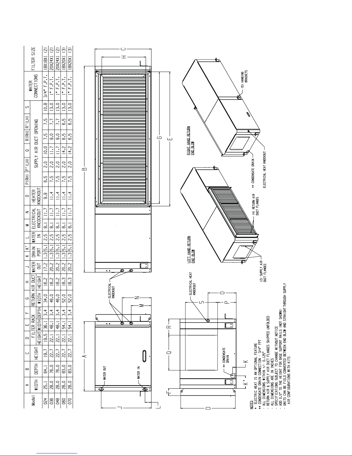
HORIZONTAL UNIT (50PTH) — Horizontal units are
designed for indoor installation only. Be sure to allow adequate
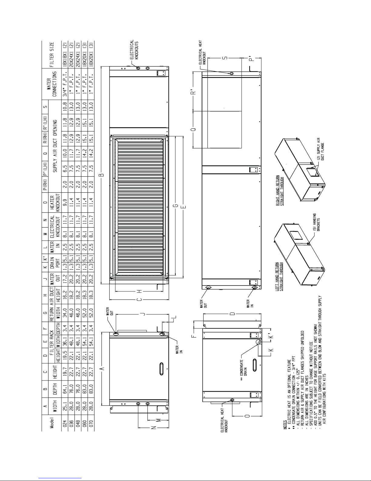
space around the unit for servicing. See Fig. 1 and 2 for overall
unit dimensions.
VERTICAL UNITS (50PTV) — Vertical units are designed
for indoor installations. While vertical units are typically
installed in a floor-level closet or a small mechanical room, the
unit access guidelines for these units are very similar to those
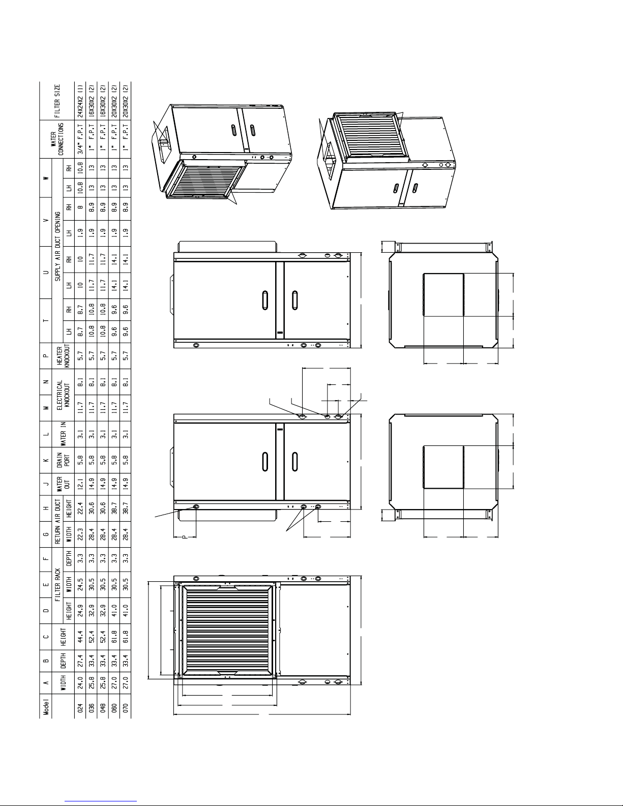
described for horizontal units. See Fig. 3 for overall dimensions.
Installation, operation and
CAUTION
1. Be sure that the location chosen for unit installation provides ambient temperatures maintained above freezing.
2. Be sure the installation location is isolated from sleeping
areas, private offices and other acoustically sensitive
spaces.
3. Be sure unit is mounted at a height sufficient to provide
an adequate slope of the condensate lines. If an appropriate slope cannot be achieved, a field-supplied condensate
pump may be required.
4. On horizontal units, allow adequate room below the unit
for condensate drain trap and do not locate the unit above
supply piping.
5. Provide sufficient space for duct connection. Do not allow the weight of the ductwork to rest on the unit.
6. Provide adequate clearance for filter replacement and
drain pan cleaning. Do not allow piping, conduit, etc. to
block filter access.
7. Provide sufficient access to allow maintenance and
servicing of the fan and fan motor, compressor and coils.
Removal of the entire unit from the closet should not be
necessary.
8. Provide an unobstructed path to the unit within the closet
or mechanical room. Space should be sufficient to allow
return air to freely enter the space.
9. Provide ready access to water valves and fittings, and
screwdriver access to unit side panels, discharge collar,
and all electrical connections.
10. Where access to side panels is limited, pre-removal of the
control box side mounting screws may be necessary for
future servicing.
STORAGE — If the equipment is not needed for immediate
installation upon its arrival at the job site, it should be left in its
shipping carton and stored in a clean, dry area. Units must only
be stored or moved in the normal upright position as indicated
by the UP arrows on each carton at all times. If unit stacking is
required, stack units as follows: vertical units less than 6 tons,
no more than two high; horizontal units less than 6 tons, no
more than three high. Do not stack units larger than 6 tons.
PROTECTION — Once the units are properly positioned on
the jobsite, cover them with either a shipping carton, vinyl film,
or an equivalent protective covering. Cap open ends of pipes
stored on the jobsite. This precaution is especially important in
areas where painting, plastering, or spraying of fireproof material, etc. is not yet complete. Foreign material that accumulates
within the units can prevent proper start-up and necessitate
costly clean-up operations.
Before installing any of the system components, be sure to
examine each pipe, fitting, and valve, and remove any dirt or
foreign material found in or on these components.
To avoid equipment damage, do not use these units as a
source of heating or cooling during the construction process. The mechanical components and filters used in these
units quickly become clogged with construction dirt and
debris which may cause system damage.
Step 2 — Check Unit — Upon receipt of shipment at
the jobsite, carefully check the shipment against the bill of
lading. Make sure all units have been received. Inspect the carton or crating of each unit, and inspect each unit for damage.
Ensure the shipping company makes proper notation of any
shortages or damage on all copies of the freight bill. Concealed
damage not discovered during unloading must be reported to
the shipping company within 15 days of receipt of shipment.
NOTE: It is the responsibility of the purchaser to file all necessary claims with the shipping company.
CAUTION
DO NOT store or install units in corrosive environments or
in locations subject to temperature or humidity extremes
(e.g., attics, garages, rooftops, etc.). Corrosive conditions
and high temperature or humidity can significantly reduce
performance, reliability, and service life. Always move
units in an upright position. Tilting units on their sides may
cause equipment damage.
2
Page 3
INSPECT UNIT — To prepare the unit for installation, complete the procedures listed below:
6. Remove the shipping bolts from compressor support
plate to maximize vibration and sound alternation.
1. Compare the electrical data on the unit nameplate with
ordering and shipping information to verify that the
correct unit has been shipped.
2. Do not remove the packaging until the unit is ready for
installation.
Failure to remove shipping brackets from spring-mounted
compressors will cause excessive noise and could cause
component failure due to added vibration.
CAUTION
3. Verify that the unit’s refrigerant tubing is free of kinks or
dents, and that it does not touch other unit components.
4. Inspect all electrical connections. Be sure connections are
clean and tight at their terminations.
5. Loosen compressor bolts until the compressor rides freely
on springs. Remove shipping restraints.
7. Remove any blower support cardboard from inlet of the
blower.
8. Locate and verify any accessory kit located in compressor
and/or blower section.
9. Remove any access panel screws that may be difficult to
remove once unit is installed.
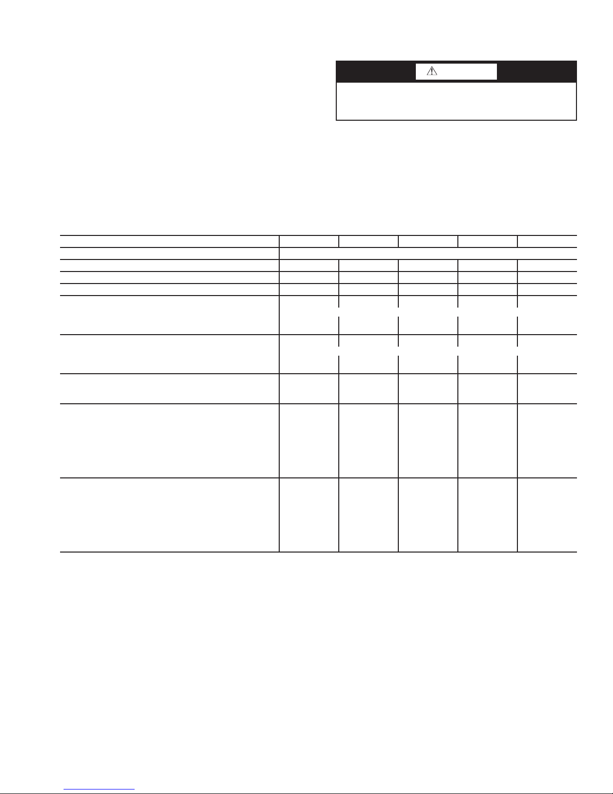
Table 1 — Physical Data — 50PTH, PTV024-070 Units
UNIT 50PTH, PTV 024 036 048 060 070
COMPRESSOR (1 each) Scroll
REFRIGERANT CHARGE VERTICAL (oz) 58 98 88 110 114
REFRIGERATION CHARGE HORIZONTAL ONLY (oz) 64 85 77 100 114
MAXIMUM WATER WORKING PRESSURE (psig/kPa) 450/3,100 450/3,100 450/3,100 450/3,100 450/3,100
CONSTANT TORQUE - FAN MOTOR/BLOWER
Fan Motor Type/Speeds Constant Torque / 5 speed
Fan Motor (Hp) 0.33 0.75 0.75 1.00 1.00
Blower Wheel Size (Dia x W) (in.) 10 x 8 11 x 9 11 x 9 11 x 11 11 x 11
ECM CONSTANT AIRFLOW - FAN MOTOR/BLOWER
Fan Motor Type/Speeds ECM Constant airflow / 3 speed
Fan Motor (Hp) 0.33 0.75 0.75 1.00 1.00
Blower Wheel Size (Dia x W) (in.) 10 x 8 11 x 9 11 x 9 11 x 11 11 x 11
WATER CONNECTION SIZE
FPT (in.)
Coaxial Coil Volume (gal) 0.33 1.18 0.62 1.07 1.12
VERTICAL CABINET
Air Coil
Dimensions (H x W) (in.) 24 x 20
Nominal Size (in.) Standard Filter - 2-in. MERV11
(L x H) (qty)
Weight (lb)
Operating 250 360 340 410 440
Shipping 350 475 450 530 560
HORIZONTAL CABINET
Air Coil
Dimensions (H x W) (in.) 18 x 31.5
Nominal Size (in.) Standard Filter - 2-in. MERV11
(L x H) (qty)
Weight (lb)
Operating 260 375 355 430 460
Shipping 360 495 470 550 580
LEGEND
ECM — Electronically Commutated Motor
3
/
4
24 x 24 (1) 16 x 30 (2) 16 x 30 (2) 20 x 30 (2) 20 x 30 (2)
18 x 18 (2) 20 x 24 (2) 20 x 24 (2) 18 x 20 (3) 18 x 20 (3)
1111
32 x 26
20 x 42
32 x 26
20 x 42
38 x 26 38 x 26
20 x 49 20 x 49
3
Page 4
*
*
Fig. 1 — 50PTH024-070 Units Supply Air Configuration - End Blow Dimensional Data
4
Page 5
*
*
Fig. 2 — 50PTH024-070 Units Supply Air Configuration - Straight Through Dimensional Data
*
5
Page 6
SUPPLY AIR
DUCT FLANGES
RETURN AIR
DUCT FLANGES
SUPPLY AIR
DUCT FLANGES
F
AA
RIGHT HAND RETURN
RETURN AIR
DUCT FLANGES
VW
ELECTRICAL HEATER
KNOCKOUT*
E
G
WATER OU T
ELECTRICAL
CONDENSATE
DRAIN**
KNOCKOUTS
J
K
WATER IN
L
LEFT HAND RETURN
N
M
F
B
U
U
T
V
W
Fig. 3 — 50PTV024-070 Dimensional Data
T
H
D
C
* ELECTRIC HEATER IS OPTIONAL FEATURE.
** CONDENSATE DRAIN CONNECTION 3/4-IN. FPT.
NOTES:
1. ALL DIMENSIONS ARE WITHIN ± 0.125 INCH.
2. RETURN AND SUPPLY AIR DUCT FLANGES SHIPPED UNFOLDED.
3. ALL DIMENSIONS ARE IN INCHES.
4. SPECIFICATIONS SUBJECT TO CHANGE WITHOUT NOTICE.
6
Page 7
Step 3 — Locate Unit — Locate the unit in an indoor
VIBRATION
PAD FULL SIZE
area that allows easy removal of the filter and access panels,
with enough room for service personnel to perform maintenance or repair. Provide sufficient room to make fluid, electrical, and duct connections. If the unit is located in a confined
space such as a closet, provisions must be made for return air to
freely enter the face of unit’s air coil. On horizontal units, allow
adequate room below the unit for a condensate drain trap and
do not locate the unit above supply piping.
Step 4 — Mount the Unit
HORIZONTAL UNIT (50PTH) — While horizontal units
may be installed on any level surface strong enough to hold
their weight, they are typically suspended above a ceiling by
threaded rods. The manufacturer recommends these be attached to the unit corners by hanger bracket kits. The rods must
be securely anchored to the ceiling. Refer to the hanging bracket assembly and installation instructions for details.
CAUTION
To avoid equipment damage, ensure horizontal units
installed above the ceiling conform to all local codes. An
auxiliary drain pan, if required by code, should be at least
4 in. larger than the bottom of the heat pump.
Plumbing connected to the heat pump must not come in direct contact with joists, trusses, walls, etc. Some applications
require an attic floor installation of the horizontal unit. In this
case the unit should be set in a full size secondary drain pan on
top of a vibration absorbing mesh.
The secondary drain pan prevents possible condensate overflow or water leakage damage to the ceiling.
The secondary drain pan is usually placed on a plywood
base isolated from the ceiling joists by additional layers of vibration absorbing mesh. In both cases, a
to this secondary pan should be run to an eave at a location that
will be noticeable.
If the unit is located in a crawl space, the bottom of the unit
must be at least 4-in. above grade to prevent flooding of the
electrical parts during heavy rains.
3
/4-in. drain connected
ductwork is not recommended as the unit’s performance will
be adversely affected.
CAUTION
To avoid equipment damage, do not connect discharge
ducts directly to the blower outlet.
The factory-provided air filter must be removed when using
a filter back return air grille. The factory filter should be left in
place on a free return system.
If the unit will be installed in a new installation which includes new ductwork, the installation should be designed using
current ASHRAE (American Society of Heating, Refrigerating
and Air-Conditioning Engineers) procedures for duct sizing. If
the unit is to be connected to existing ductwork, a check should
be made to assure that the duct system has the capacity to handle the air required for the unit application. If the duct system is
too small, larger ductwork should be installed. Check for existing leaks and repair.
The duct system and all diffusers should be sized to handle
the designed airflow quietly. To maximize sound attenuation of
the unit blower, the supply and return air plenums should be insulated. There should be no direct straight air path through the
return air grille into the heat pump. The return air inlet to the
heat pump must have at least one 90-degree turn away from the
space return air grille. If air noise or excessive airflow are a
problem, the blower speed can be changed to a lower speed to
reduce airflow.
IMPORTANT: Horizontal units must be installed pitched
toward the condensate drain connection
1
/8-in. per foot.
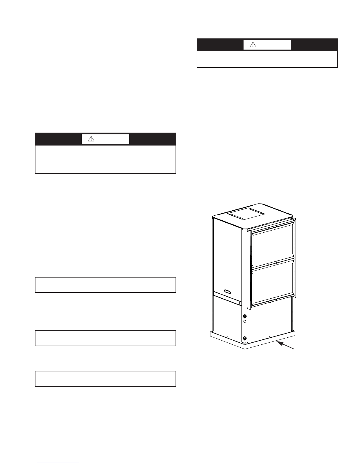
VERTICAL UNITS (50PTV) — Vertical units should be
mounted level on a vibration absorbing pad slightly larger than
the base to minimize vibration transmission to the building
structure. It is not necessary to anchor the unit to the floor. (See
Fig. 4.)
IMPORTANT: On vertical units the condensate drain pan
is internally sloped. There is no internal P-Trap.
Step 5 — Check Duct System — A supply air out-
let collar and return air duct flange are provided on all units to
facilitate duct connections.
IMPORTANT: Supply air duct and return air duct flanges
are shipped unfolded with unit.
Fold the duct flange outwards along the perforated line. Re-
fer to Fig. 1-3 for physical dimensions of the collar and flange.
A flexible connector is recommended for supply and return
air duct connections on metal duct systems. All metal ducting
should be insulated with a minimum of 1 in. duct insulation to
avoid heat loss or gain and prevent condensate forming during
the cooling operation. Application of the unit to uninsulated
Fig. 4 — Vertical Unit on Vibration Pad
Step 6 — Install Condensate Drain — A drain
line must be connected to the heat pump and pitched away
from the unit a minimum of
densate to flow away from the unit. (See Fig. 5.)
This connection must be in conformance with local plumbing codes. A trap must be installed in the condensate line to ensure free condensate flow.
1
/8-in. per foot to allow the con-
7
Page 8
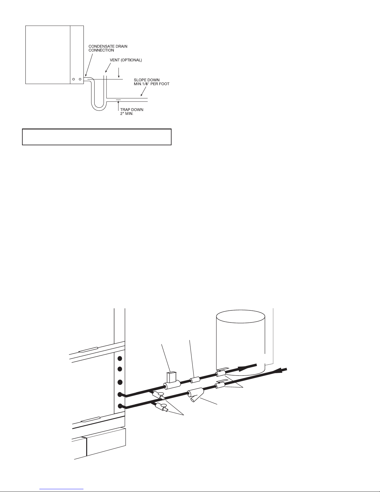
Fig. 5 — Condensate Trapping
Boiler
Drains
(field-installed)
Strainer (field-installed accessory)
(16 to 20 mesh recommended for
filter sediment)
Shut-Off
Valve (field-installed accessory)
Water
Control
Valve
(field-installed
accessory)
Flow
Regulator
(field-installed
accessory)
Pressure
Tank
Water Out
Water In
From Pump
IMPORTANT: Horizontal heat pump drain pan is not internally slopped.
A vertical air vent is sometimes required to avoid air pockets. The length of the trap depends on the amount of positive or
negative pressure on the drain pan. A second trap must not be
included.
Step 7 — Pipe Connections — Depending on the
application, there are 3 types of WSHP piping systems to
choose from: water loop, ground-water and ground loop. Refer
to Piping Section of Carrier System Design Manual for additional information.
All WSHP units use low temperature soldered female pipe
thread fittings for water connections to prevent annealing and
out-of-round leak problems which are typically associated with
high temperature brazed connections. Refer to Table 1 for connection sizes. When making piping connections, consider the
following:
• Use a backup wrench when making screw connections to
unit to prevent internal damage to piping.
• Insulation may be required on piping to avoid condensa-
tion in the case where fluid in loop piping operates at
temperatures below dew point of adjacent air.
• Piping systems that contain steel pipes or fittings may be
subject to galvanic corrosion. Dielectric fittings may be
used to isolate the steel parts of the system to avoid gal-
vanic corrosion.
WATER LOOP APPLICATIONS — Water loop applications
usually include a number of units plumbed to a common piping system. Maintenance to any of these units can introduce air
into the piping system. Therefore, air elimination equipment
comprises a major portion of the mechanical room plumbing.
The flow rate is usually set between 2.25 and 3.5 gpm per
ton of cooling capacity. For proper maintenance and servicing,
pressure-temperature ports are necessary for temperature and
flow verification.
Cooling tower/boiler systems typically utilize a common
loop maintained at 50 to 100 F. The use of a closed circuit
evaporative cooling tower with a secondary heat exchange between the tower and the water loop is recommended. If an open
type cooling tower is used continuously, chemical treatment
and filtering will be necessary.
In addition to complying with any applicable codes, consider the following for system piping:
• Piping systems using water temperatures below 50 F
require
1
/2-in. closed cell insulation on all piping sur-
faces to eliminate condensation.
• Avoid all plastic to metal threaded fittings due to the
potential to leak. Use a flange fitted substitute.
• Teflon tape thread sealant is recommended to minimize
internal fouling of the heat exchanger.
• Use backup wrench. Do not overtighten connections.
• Route piping to avoid service access areas to unit.
• Flush the piping system prior to operation to remove dirt
and foreign materials from the system.
GROUND-WATER APPLICATIONS — Typical groundwater piping is shown in Fig. 6. In addition to complying
with any applicable codes, consider the following for system piping:
• Install shut-off valves for servicing.
• Install pressure-temperature plugs to measure flow and
temperature.
• Connect boiler drains and other valves using a “T” con-
nector to allow acid flushing for the heat exchanger.
• Do not overtighten connections.
• Route piping to avoid service access areas to unit.
• Use PVC SCH80 or copper piping material.
NOTE: PVC SCH40 should not be used due to system high
pressure and temperature extremes.
Fig. 6 — Typical Ground-Water Piping Installation
8
Page 9
Water Supply and Quantity
— Check water supply. Water
supply should be plentiful and of good quality. See Table 2 for
water quality guidelines.
IMPORTANT: Failure to comply with the above required
water quality and quantity limitations and the closedsystem application design requirements may cause damage
to the tube-in-tube heat exchanger. This damage is not the
responsibility of the manufacturer.
In all applications, the quality of the water circulated
through the heat exchanger must fall within the ranges listed in
the Water Quality Guidelines table. Consult a local water treatment firm, independent testing facility, or local water authority
for specific recommendations to maintain water quality within
the published limits.
Table 2 — Water Quality Guidelines
GROUND-LOOP APPLICATIONS — Temperatures between
20 and 110 F and a cooling capacity of 2.25 to 3 gpm of flow
per ton is recommended. In addition to complying with any
applicable codes, consider the following for system piping:
• Limit piping materials to only polyethylene fusion in the
buried sections of the loop.
• Do not use galvanized or steel fittings at any time due to
corrosion.
• Avoid all plastic to metal threaded fittings due to the
potential to leak. Use a flange fitted substitute.
• Do not overtighten connections.
• Route piping to avoid service access areas to unit.
• Use pressure-temperature plugs to measure flow of pressure drop.
CONDITION HX MATERIAL*
Scaling Potential — Primary Measurement
Above the given limits, scaling is likely to occur. Scaling indexes should be calculated using the limits below.
pH/Calcium
Hardness Method
Index Limits for Probable Scaling Situations (Operation outside these limits is not recommended.)
Scaling indexes should be calculated at 150 F for direct use and HWG applications, and at 90 F for indirect HX use. A monitoring plan should be implemented.
Ryznar Stability Index
Langelier Saturation Index
Iron Fouling
Corrosion Prevention††
Erosion and Clogging
HWG — Hot Water Generator
HX — Heat Exchanger
N/A — Design Limits Not Applicable Considering Recirculating
NR — Application Not Recommended
SS — Stainless Steel
*Heat exchanger materials considered are copper, cupronickel, 304 SS
†Closed recirculating system is identified by a closed pressurized piping
**Recirculating open wells should obser ve the open recirculating design
2+
Iron Fe
(Bacterial Iron Potential)
Iron Fouling
pH
Hydrogen Sulfide (H
Ammonia Ion as Hydroxide,
Chloride, Nitrate and Sulfate
Compounds
Maximum Chloride Levels Maximum allowable at maximum water temperature.
Particulate Size and Erosion
Brackish
(stainless steel), 316 SS, titanium.
system.
considerations.
(Ferrous)
Potabl e Water
S)
2
LEGEND
All N/A pH < 7.5 and Ca Hardness, <100 ppm
All N/A
All N/A
All N/A
All N/A
All
All N/A
All N/A
Copper N/A
Cupronickel N/A <150 ppm NR NR
304 SS N/A <400 ppm <250 ppm <150 ppm
316 SS N/A <1000 ppm <550 ppm <375 ppm
Titanium N/A >1000 ppm >550 ppm >375 ppm
All
All N/A
CLOSED
RECIRCULATING†
6 - 8.5
Monitor/treat as needed.
<10 ppm of particles and a
maximum velocity of 6 fps.
Filtered for maximum
800 micron size.
OPEN LOOP AND RECIRCULATING WELL**
6.0 - 7.5
If >7.5 minimize steel pipe use.
–0.5 to +0.5
Based upon 150 F HWG and direct well, 85 F indirect well HX.
If Fe2+ (ferrous) >0.2 ppm with pH 6 - 8, O2<5 ppm check for iron bacteria.
Minimize steel pipe below 7 and no open tanks with pH <8.
At H2S>0.2 ppm, avoid use of copper and cupronickel piping or HXs.
Copper alloy (bronze or brass) cast components are okay to <0.5 ppm.
50 F (10 C) 75 F (24 C) 100 F (38 C)
<20 ppm NR NR
<10 ppm (<1 ppm “sandfree” for reinjection) of particles and a maximum
velocity of 6 fps. Filtered for maximum 800 micron size. Any particulate that
is not removed can potentially clog components.
Use cupronickel heat exchanger when concentrations of calcium or sodium
chloride are greater than 125 ppm are present. (Seawater is approximately
25,000 ppm.)
††If the concentration of these corrosives exceeds the maximum allow-
able level, then the potential for serious corrosion problems exists.
Sulfides in the water quickly oxidize when exposed to air, requiring that
no agitation occur as the sample is taken. Unless tested immediately
at the site, the sample will require stabilization with a few drops of one
Molar zinc acetate solution, allowing accurate sulfide determination up
to 24 hours after sampling. A low pH and high alkalinity can cause
system problems, even when both values are within ranges shown.
The term pH refers to the acidity, basicity, or neutrality of the water
supply. Below 7.0, the water is considered to be acidic. Above 7.0,
water is considered to be basic. Neutral water registers a pH of 7.0.
To convert ppm to grains per gallon, divide by 17. Hardness in mg/l is
equivalent to ppm. considered to be basic. Neutral water contains a
pH of 7.0. To convert ppm to grains per gallon, divide by 17. Hardness
in mg/l is equivalent to ppm.
If <–0.5 minimize steel pipe use.
<0.2 ppm (Ferrous)
<0.5 ppm of Oxygen
Above this level deposition will occur.
6 - 8.5
<0.5 ppm
Rotten egg smell appears at 0.5 ppm level.
<0.5 ppm
9
Page 10
INSTALLATION OF SUPPLY AND RETURN HOSE
KIT — Follow these piping guidelines.
1. Install a drain valve at the base of each supply and return
riser to facilitate system flushing.
2. Install shutoff/balancing valves and unions at each unit to
permit unit removal for servicing.
3. Place strainers at the inlet of each system circulating
pump.
4. Select the proper hose length to allow slack between connection points. Hoses may vary in length by +2% to –4%
under pressure.
5. Refer to Table . Do not exceed the minimum bend radius
for the hose selected. Exceeding the minimum bend radius may cause the hose to collapse, which reduces water
flow rate. Install an angle adapter to avoid sharp bends in
the hose when the radius falls below the required minimum.
NOTE: Piping must comply with all applicable codes.
Table 3 — Metal Hose Minimum Bend Radii
HOSE DIAMETER (in.) MINIMUM BEND RADII (in.)
1
/
2
3
/
4
15
21/
2
4
1
/
2
Insulation is not required on loop water piping except where
the piping runs through unheated areas or outside the building
or when the loop water temperature is below the minimum expected dew point of the pipe ambient. Insulation is required if
loop water temperature drops below the dew point.
CAUTION
Do not bend or kink supply lines or hoses.
Pipe joint compound is not necessary when Teflon* threaded tape is pre-applied to hose assemblies or when flared-end
connections are used. If pipe joint compound is preferred, use
compound only in small amounts on the male pipe threads of
the fitting adapters. Prevent sealant from reaching the flared
surfaces of the joint.
NOTE: When anti-freeze is used in the loop, assure that it is
compatible with Teflon tape or pipe joint compound employed.
Maximum allowable torque for brass fittings is 30 ft-lb. If a
torque wrench is not available, tighten finger-tight plus one
quarter turn. Tighten steel fittings as necessary.
Optional pressure-rated hose assemblies designed specifically for use with Carrier units are available. Similar hoses can
be obtained from alternate suppliers. Supply and return hoses
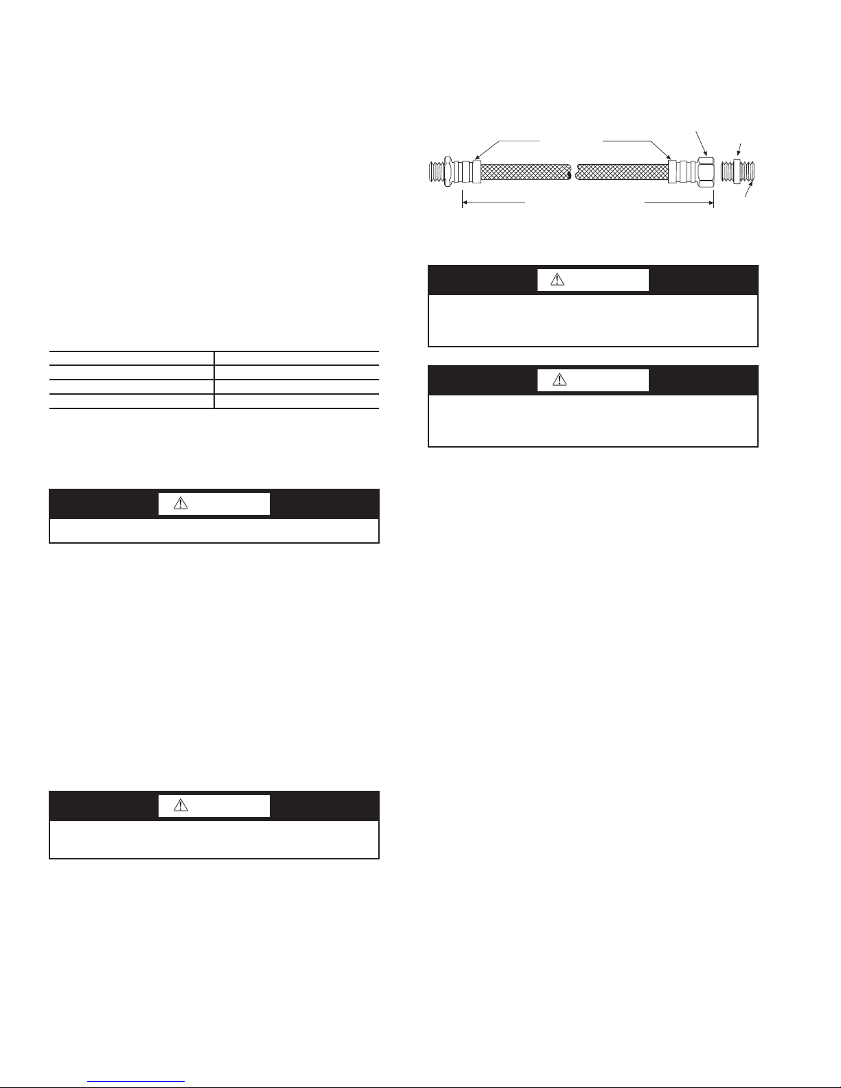
are fitted with swivel-joint fittings at one end to prevent kinking during installation.
Refer to Fig. 7 for an illustration of a supply/return hose kit.
Male adapters secure hose assemblies to the unit and risers. Install hose assemblies properly and check them regularly to
avoid system failure and reduced service life.
Rib Crimped
Length
(2 ft Length Standard)
Swivel
Brass
Fitting
Brass
Fitting
MPT
Fig. 7 — Supply/Return Hose Kit
Step 8 — Wire Field Power Supply
WARNING
To avoid possible injury or death due to electrical shock,
open the power supply disconnect switch and secure it in
an open position during installation.
CAUTION
Operating the unit with improper line voltage or with
excessive phase imbalance is hazardous to the unit and
constitutes abuse and is not covered under warranty.
All field wiring must comply with local and national fire,
safety and electrical codes. Power to the unit must be within the
operating voltage range indicated on the unit’s nameplate.
Properly sized fuses or HACR circuit breakers must be installed for branch circuit protection. See unit nameplate for
maximum fuse or breaker size. The unit is provided with a concentric knock-out for attaching common trade sizes of conduit;
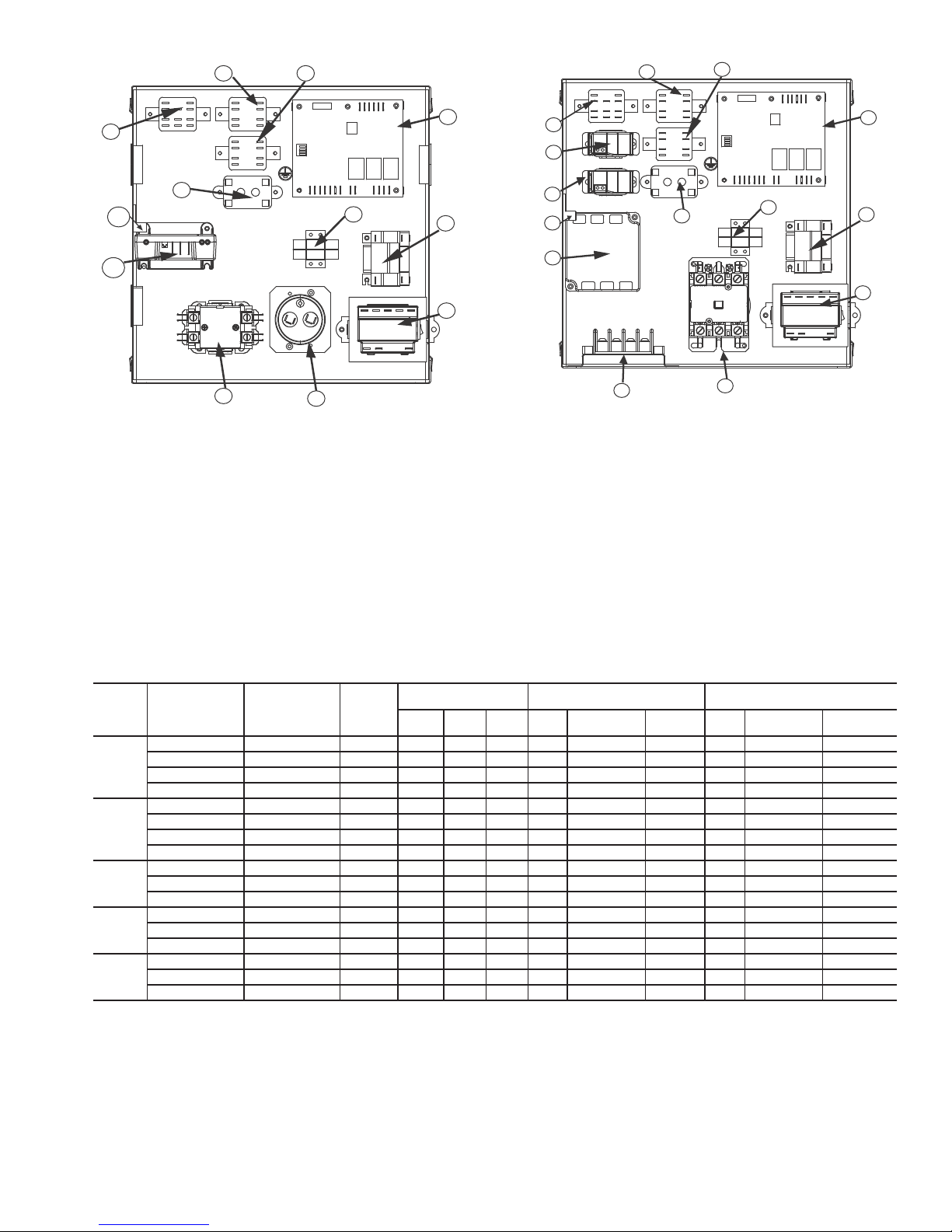
route power supply wiring through this opening. Always connect the ground lead to the grounding lug provided in the control box and power leads to the line side of compressor contactor as indicated on the wiring diagram. See Fig. 8 and 9 for
control box layout. See Tables 4-6 for additional electrical data.
Units supplied with internal electric heat require two separate power supplies: Unit compressor and electric heat, blower
motor and control circuit. Refer to Fig. 10-17. See data plate
for minimum circuit ampacities and maximum fuse/breaker
sizing.
CAUTION
Backup wrench is required when tightening water connections to prevent water line damage.
* Registered trademark of DuPont.
10
Page 11
4
5
16
3
2
21
6
7
8
9
1
10
5
3
1—Compressor Contactor
2—Emergency Relay (Option)
3—Second Stage Relay
4—Hot Gas Reheat Relay (Option)
5—Cooling Relay
6—Complete C Control
7—Terminal Block Low-Voltage
8—Auxiliary Relay (Option)
9—Transformer
10 — Capacitor
16 — Comfort Alert Module (Option)
21 — Ground Lug
Fig. 8 — Single-Phase Unit
Control Box Layout
4
13
14
21
2
12
15
1—Compressor Contactor
2—Emergency Relay (Option)
3—Second Stage Relay
4—Hot Gas Reheat Relay (Option)
5—Cooling Relay
6—Complete C Control
7—Terminal Block Low-Voltage
8—Auxiliary Relay (Option)
9—Transformer
12 — Phase Monitor
13 — Fan Status Switch (Option)
14 — Pump Status Switch (Option)
15 — Terminal Block 460-v Units (Option)
21 — Ground Lug
1
Fig. 9 — Three-Phase Unit
Control Box Layout
6
7
8
9
UNIT SIZE COMPRESSOR
8733902168 208/230-1-60 197/253 1 11.7 58.3 2.8 17.4 25 2.8 17.4 25
50PT024
50PT036
50PT048
50PT060
50PT070
ECM — Electronically Commutated Motor
FLA — Full Load Amps
HACR — Heating, Air Conditioning and Refrigeration
LRA — Locked Rotor Amps
MAX — Maximum
MIN — Minimum
RLA — Rated Load Amps
8733801381 265/277-1-60 — 1 9.1 54.0 2.6 14.0 20 2.6 14.0 20
8733801385 208/230-3-60 197/253 1 6.5 55.4 2.8 10.9 15 2.8 10.9 15
8733801392 460-3-60 — 1 3.5 28.0 2.1 6.4 15 2.6 6.9 15
8733902169 208/230-1-60 197/253 1 15.3 83.0 6.0 25.1 35 6.8 25.9 35
8733801382 265/277-1-60 — 1 13.0 72.0 4.9 21.2 30 5.5 21.8 35
8733801386 208/230-3-60 197/253 1 11.6 73.0 6.0 20.5 30 6.8 21.3 30
8733903844 460-3-60 - 1 5.7 38.0 3.2 10.4 15 5.5 12.6 15
8733902170 208/230-1-60 197/253 1 21.2 104.0 6.0 32.4 50 6.8 33.2 50
8733801387 208/230-3-60 197/253 1 14.0 83.1 6.0 23.5 35 6.8 24.3 35
8733801393 460-3-60 - 1 6.4 41.0 3.2 11.3 15 5.5 13.5 15
8733902171 208/230-1-60 197/253 1 27.1 152.9 7.6 41.5 60 9.1 43.0 70
8733801388 208/230-3-60 197/253 1 16.5 110.0 7.6 28.3 40 9.1 29.8 45
8733801394 460-3-60 - 1 7.2 52.0 4.0 13.1 20 6.9 16.0 20
8733902172 208/230-1-60 197/253 1 29.7 179.2 7.6 44.7 70 9.1 46.2 70
8733801389 208/230-3-60 197/253 1 17.6 136.0 7.6 29.6 45 9.1 31.1 45
8733801395 460-3-60 - 1 8.5 66.1 4.0 14.6 20 6.9 17.5 25
LEGEND
VOLTAGE
RATED
v-ph-Hz
Table 4 — 50PTH,PTV Blower Motor Electrical Data
VOLTAGE
MIN/MAX
COMPRESSOR
QTY RLA LRA FLA
TOTAL UNIT CONST TORQUE
MOTOR (STANDARD)
MIN CIRCUIT
AMPS
MAX FUSE/
HACR
TOTAL UNIT ECM CONST airflow
MOTOR (OPTION)
FLA
MIN CIRCUIT
AMPS
MAX FUSE/
HACR
11
Page 12
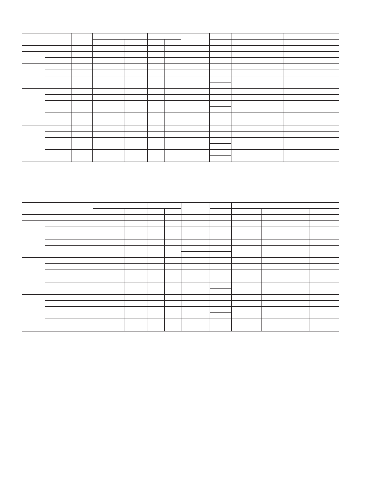
Table 5 — 50PTH,PTV Units with Electric Heat Option — Constant Torque Motor Electrical Data
UNIT SIZE
EH — Electric Heat
FLA — Full Load Amps
MCA — Minimum Circuit Amps
MOP — Maximum Overcurrent Protection
EH RATED
kW
024 4.8 1 4,800 3,600 20.0 17.3 2.8 — 28.5 25.1 30 30
036
048
060
070
4.8 1 4,800 3,600 20.0 17.3 6.0 — 32.5 29.1 35 30
9.6 1 9,600 7,200 40.0 34.6 6.0 — 57.5 50.8 60 60
4.8 1 4,800 3,600 20.0 17.3 6.0 — 32.5 29.1 35 30
9.6 1 9,600 7,200 40.0 34.6 6.0 — 57.5 50.8 60 60
14.4 2 14,400 10,800 60.0 51.9 6.0
4.8 1 4,800 3,600 20.0 17.3 7.6 — 34.5 31.1 35 35
9.6 1 9,600 7,200 40.0 34.6 7.6 — 59.5 52.8 60 60
14.4 2 14,400 10,800 60.0 51.9 7.6
19.2 2 19,200 14,000 80.0 69.2 7.6
4.8 1 4,800 3,600 20.0 17.3 7.6 — 34.5 31.1 35 35
9.6 1 9,600 7,200 40.0 34.6 7.6 — 52.8 52.8 60 60
14.4 2 14,400 10,800 60.0 51.9 7.6
19.2 2 19,200 14,000 80.0 69.2 7.6
STAGE
LEGEND
HEATER WATTS HEATER AMPS
240 208
240 208 FUSES 240 208 240 208
MOTOR FLA
(A)
CIRCUIT
F1/F2
F3/F4
F1/F2
F3/F4
F1/F2
F3/F4
F1/F2
F3/F4
F1/F2
F3/F4
MCA
82.5 72.4 90 80
84.5 74.4 90 80
109.5 96.0 110 100
84.5 74.4 90 80
109.5 96.0 110 100
MOP
Table 6 — 50PTH,PTV Units with Electric Heat Option — Constant Airflow ECM Motor Electrical Data
UNIT SIZE
EH — Electric Heat
FLA — Full Load Amps
MCA — Minimum Circuit Amps
MOP — Maximum Overcurrent Protection
EH RATED
kW
024 4.8 1 4,800 3,600 20.0 17.3 2.8 — 28.5 25.1 30 30
036
048
060
070
4.8 1 4,800 3,600 20.0 17.3 6.8 — 33.5 30.1 35 35
9.6 1 9,600 7,200 40.0 34.6 6.8 — 58.5 51.8 60 60
4.8 1 4,800 3,600 20.0 17.3 6.8 — 33.5 30.1 35 35
9.6 1 9,600 7,200 40.0 34.6 6.8 — 58.5 51.8 60 60
14.4 2 14,400 10,800 60.0 51.9
4.8 1 4,800 3,600 20.0 17.3 9.1 — 36.4 33.0 40 35
9.6 1 9,600 7,200 40.0 34.6 9.1 — 61.4 54.6 70 60
14.4 2 14,400 10,800 60.0 51.9 9.1
19.2 2 19,200 14,000 80.0 69.2 9.1
4.8 1 4,800 3,600 20.0 17.3 9.1 — 36.4 33.0 40 35
9.6 1 9,600 7,200 40.0 34.6 9.1 — 61.4 54.6 70 60
14.4 2 14,400 10,800 60.0 51.9 9.1
19.2 2 19,200 14,000 80.0 69.2 9.1
STAGE
LEGEND
HEATER WATTS HEATER AMPS
240 208
240 208 FUSES 240 208 240 208
MOTOR FLA
(A)
6.8 F1/F2
6.8 F3/F4
CIRCUIT
F1/F2
F3/F4
F1/F2
F3/F4
F1/F2
F3/F4
F1/F2
F3/F4
MCA
83.5 73.4 90 80
86.4 76.3 90 80
111.4 97.9 125 100
86.4 76.3 90 80
111.4 97.9 125 100
MOP
12
Page 13
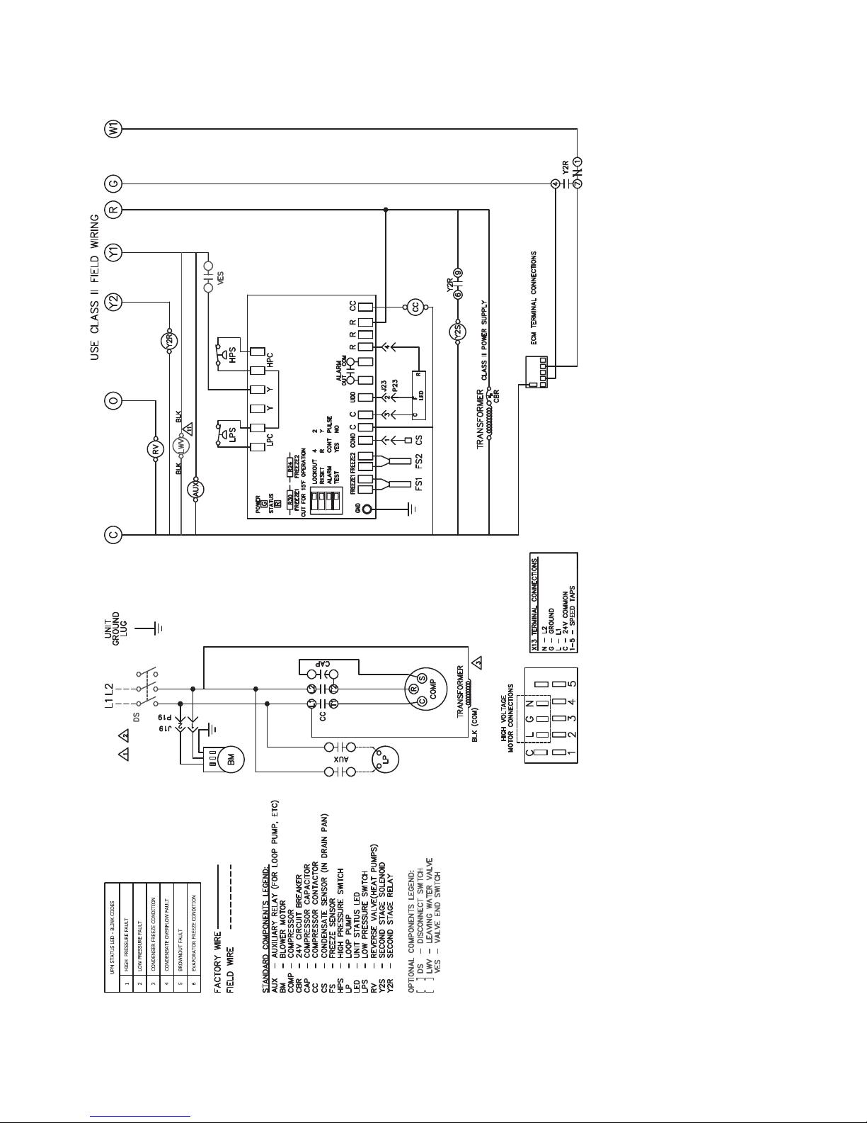
NOTES:
1. SEE UNIT NAMEPLATE FOR ELECTRICAL RATING.
2. ALL FIELD WIRING MUST BE IN ACCORDANCE WITH NEC-NFPA #70, COPPER CONDUCTORS ONLY.
3. 208/230V UNITS ARE FACTORY WIRED FOR 230V OPERATION. FOR 208V OPERATION, REMOVE LEAD FROM 240 TERMINAL
AND CONNECT IT TO 208. CAP ALL UNUSED TERMINALS.
4. UPM-1 INCLUDES BUILT IN: 270-300 SECOND RANDOM START
300 SECOND DELAY ON BREAK
120 SECOND LOW PRESSURE BYPASS
5. “TEST” DIP SWITCH REDUCES DELAYS TO 10 SEC WHEN SET TO YES. MUST BE SET TO “NO” FOR NORMAL OPERATION.
6. “FREEZE SENSOR” ON CONDENSER WILL OPERATE AT 26 F BY DEFAULT, IF 15 F OPERATION IS REQUIRED JUMPER R30 MUST BE CUT.
IF FREEZE SENSOR IS NOT INSTALLED A JUMPER SHALL BE INSTALLED BETWEEN THE FREEZE1 OR FREEZE2 SENSOR TERMINALS.
7. “ALARM OUTPUT” DIP SWITCH MUST BE SET TO “PULSE” IF BLINKING T-STAT SERVICE LIGHT IS DESIRED.
8. DEFAULT SETTINGS FOR COMPLETE C BOARD FROM FACTORY SHOWN.
9. ALARM OUTPUT IS NORMALLY OPEN (NO) DRY CONTACT. IF 24 VAC IS NEEDED, CONNECT R TO ALR-COM TERMINAL. 24 VAC WILL BE SENSED
ON THE ALR-OUT WHEN THE UNIT IS IN ALARM CONDITION. OUTPUT WILL BE PULSED IF PULSE IS SELECTED.
10. CHECK FOR PROPER PHASE ROTATION ON UNITS WITH SCROLL COMPRESSORS. REVERSE ROTATION WILL DAMAGE THE COMPRESSOR AND VOID UNIT WARRANTY.
11. FACTORY-MOUNTED LOOP PUMP OR TWO-WAY WATER VALVE. BOTH DEVICES WILL NOT BE PRESENT IN THE SAME UNIT.
COMPLETE C
SEE NOTES 5-9
Fig. 10 — Constant Torque Motor, Single Phase/Single Stage Two Step, Complete C Control
13
Page 14
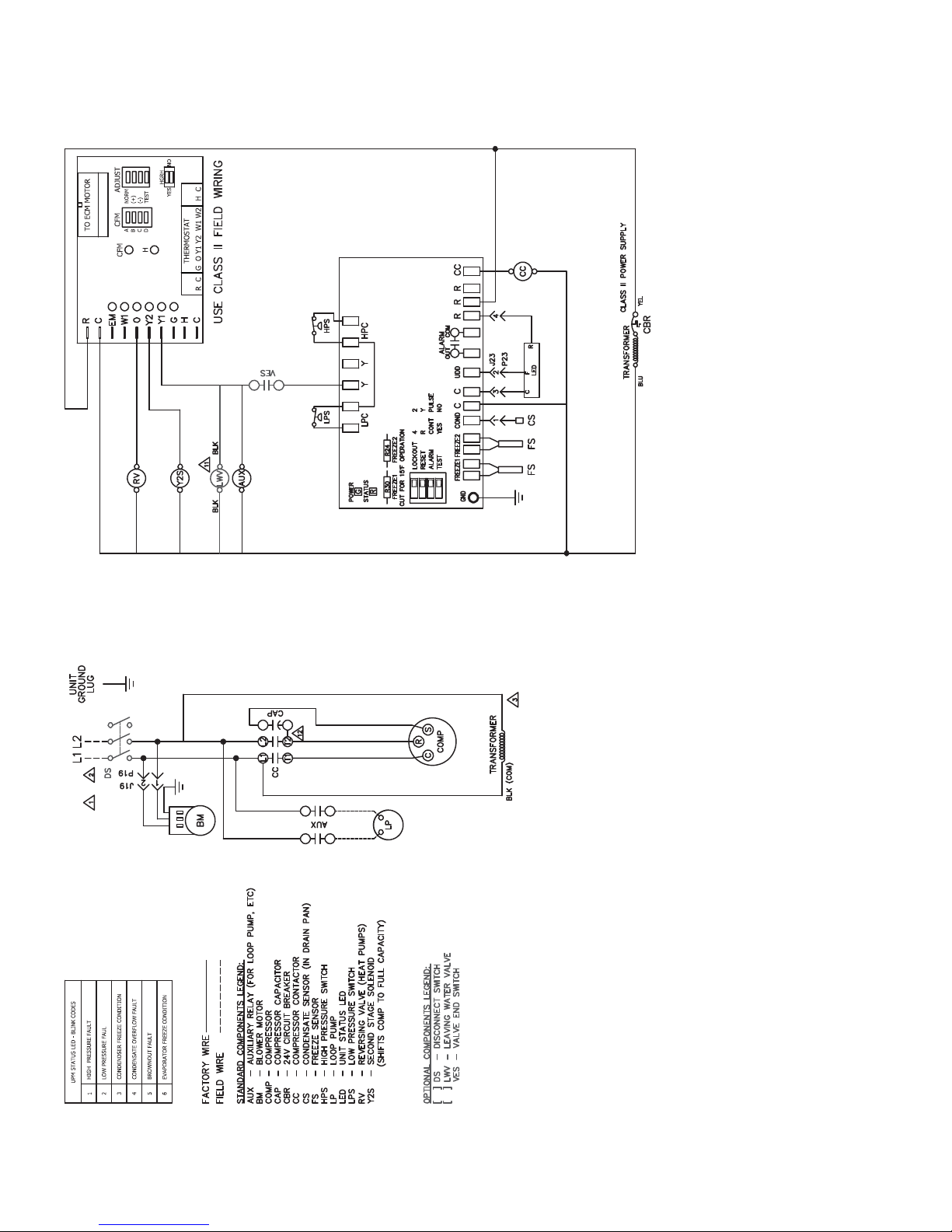
NOTES:
1. SEE UNIT NAMEPLATE FOR ELECTRICAL RATING.
2. ALL FIELD WIRING MUST BE IN ACCORDANCE WITH NEC-NFPA #70, COPPER CONDUCTORS ONLY.
3. 208/230V UNITS ARE FACTORY WIRED FOR 230V OPERATION. FOR 208V OPERATION, REMOVE LEAD FROM 240 TERMINAL
AND CONNECT IT TO 208. CAP ALL UNUSED TERMINALS.
4. UPM-1 INCLUDES BUILT IN: 270-300 SECOND RANDOM START
300 SECOND DELAY ON BREAK
120 SECOND LOW PRESSURE BYPASS
5. “TEST” DIP SWITCH REDUCES DELAYS TO 10 SEC WHEN SET TO YES. MUST BE SET TO “NO” FOR NORMAL OPERATION.
6. “FREEZE SENSOR” ON CONDENSER WILL OPERATE AT 26 F BY DEFAULT, IF 15 F OPERATION IS REQUIRED JUMPER R30 MUST BE CUT.
IF FREEZE SENSOR IS NOT INSTALLED A JUMPER SHALL BE INSTALLED BETWEEN THE FREEZE1 OR FREEZE2 SENSOR TERMINALS.
7. “ALARM OUTPUT” DIP SWITCH MUST BE SET TO “PULSE” IF BLINKING T-STAT SERVICE LIGHT IS DESIRED.
8. DEFAULT SETTINGS FOR COMPLETE C BOARD FROM FACTORY SHOWN.
9. ALARM OUTPUT IS NORMALLY OPEN (NO) DRY CONTACT. IF 24 VAC IS NEEDED, CONNECT R TO ALR-COM TERMINAL. 24 VAC WILL BE SENSED
ON THE ALR-OUT WHEN THE UNIT IS IN ALARM CONDITION. OUTPUT WILL BE PULSED IF PULSE IS SELECTED.
10. FACTORY-MOUNTED LOOP PUMP OR TWO-WAY WATER VALVE. BOTH DEVICES WILL NOT BE PRESENT IN THE SAME UNIT.
COMPLETE C
SEE NOTES 5-9
14
Fig. 11 — Constant Airflow ECM Motor, Single Phase/Single Stage Two Step, Complete C Control
Page 15
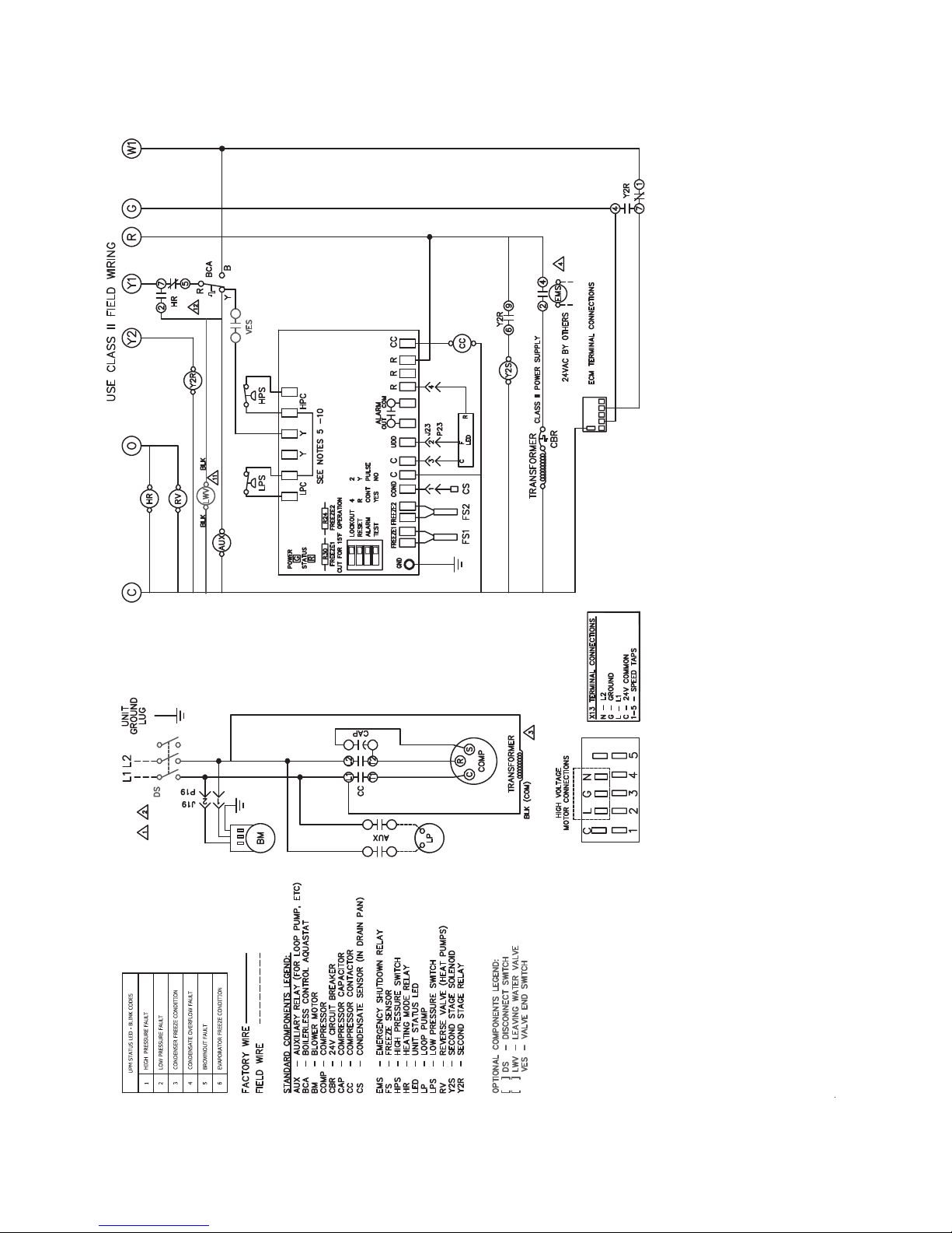
DELUXE D
ECM – ELECTRONICALLY COMMUTATED MOTOR
15
NOTES:
1. SEE UNIT NAMEPLATE FOR ELECTRICAL RATING.
2. ALL FIELD WIRING MUST BE IN ACCORDANCE WITH NEC-NFPA #70, COPPER CONDUCTORS ONLY.
3. 208/230V UNITS ARE FACTORY WIRED FOR 230V OPERATION. FOR 208V OPERATION, REMOVE LEAD AND REPLACE WITH
RED LEAD. CAP ALL UNUSED LEADS.
4. FOR ALTERNATIVE EMS COIL VOLTAGES CONSULT FACTORY.
5. UPM-1 INCLUDES BUILT IN: 270-300 SECOND RANDOM START
300 SECOND DELAY ON BREAK
120 SECOND LOW PRESSURE BYPASS
6. “TEST” DIP SWITCH REDUCES DELAYS TO 10 SEC WHEN SET TO YES. MUST BE SET TO “NO” FOR NORMAL OPERATION.
7. “FREEZE SENSOR” ON CONDENSER WILL OPERATE AT 26 F BY DEFAULT, IF 15 F OPERATION IS REQUIRED JUMPER R30 MUST BE CUT.
IF FREEZE SENSOR IS NOT INSTALLED A JUMPER SHALL BE INSTALLED BETWEEN THE FREEZE1 OR FREEZE2 SENSOR TERMINALS.
8. “ALARM OUTPUT” DIP SWITCH MUST BE SET TO “PULSE” IF BLINKING T-STAT SERVICE LIGHT IS DESIRED.
9. DEFAULT SETTINGS FOR DELUXE D BOARD FROM FACTORY SHOWN.
10. ALARM OUTPUT IS NORMALLY OPEN (NO) DRY CONTACT. IF 24 VAC IS NEEDED, CONNECT R TO ALR-COM TERMINAL. 24 VAC WILL BE SENSED
ON THE ALR-OUT WHEN THE UNIT IS IN ALARM CONDITION. OUTPUT WILL BE PULSED IF PULSE IS SELECTED.
11. FACTORY-MOUNTED LOOP PUMP OR TWO-WAY WATER VALVE. BOTH DEVICES WILL NOT BE PRESENT IN THE SAME UNIT.
12. BCA CONTACTS R-Y OPEN ON DROP IN WATER TEMPERATURE AND R-B CLOSE.
Fig. 12 — Constant Torque Motor, Single Phase/Single Stage Two Step, Deluxe D Control
Page 16
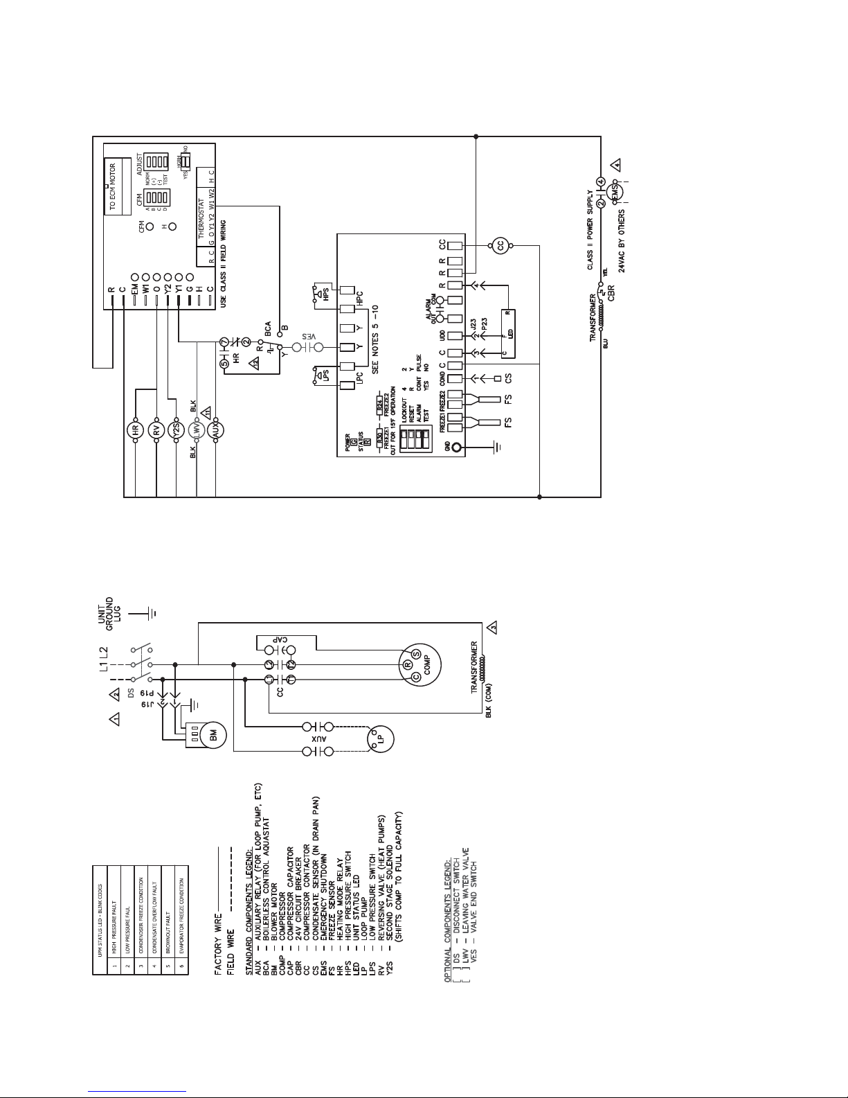
NOTES:
1. SEE UNIT NAMEPLATE FOR ELECTRICAL RATING.
2. ALL FIELD WIRING MUST BE IN ACCORDANCE WITH NEC-NFPA #70, COPPER CONDUCTORS ONLY.
3. 208/230V UNITS ARE FACTORY WIRED FOR 230V OPERATION. FOR 208V OPERATION, REMOVE LEAD
FROM 240 TERMINAL AND CONNECT IT TO 208. CAP ALL UNUSED TERMINALS.
4. FOR ALTERNATIVE EMS COIL VOLTAGES CONSULT FACTORY.
5. UPM-1 INCLUDES BUILT IN: 270-300 SECOND RANDOM START
300 SECOND DELAY ON BREAK
120 SECOND LOW PRESSURE BYPASS
6. “TEST” DIP SWITCH REDUCES DELAYS TO 10 SEC WHEN SET TO YES. MUST BE SET TO “NO” FOR NORMAL OPERATION.
7. “FREEZE SENSOR” ON CONDENSER WILL OPERATE AT 26 F BY DEFAULT, IF 15 F OPERATION IS REQUIRED JUMPER R30 MUST BE CUT.
IF FREEZE SENSOR IS NOT INSTALLED A JUMPER SHALL BE INSTALLED BETWEEN THE FREEZE1 OR FREEZE2 SENSOR TERMINALS.
8. “ALARM OUTPUT” DIP SWITCH MUST BE SET TO “PULSE” IF BLINKING T-STAT SERVICE LIGHT IS DESIRED.
9. DEFAULT SETTINGS FOR DELUXE D BOARD FROM FACTORY SHOWN.
10. ALARM OUTPUT IS NORMALLY OPEN (NO) DRY CONTACT. IF 24 VAC IS NEEDED, CONNECT R TO ALR-COM TERMINAL. 24 VAC WILL BE SENSED
ON THE ALR-OUT WHEN THE UNIT IS IN ALARM CONDITION. OUTPUT WILL BE PULSED IF PULSE IS SELECTED.
11. FACTORY-MOUNTED LOOP PUMP OR TWO-WAY WATER VALVE. BOTH DEVICES WILL NOT BE PRESENT IN THE SAME UNIT.
12. BCA CONTACTS R-Y OPEN ON DROP IN WATER TEMPERATURE AND R-B CLOSE.
DELUXE D
16
Fig. 13 — Constant Airflow ECM Motor, Single Phase/Single Stage Two Step, Deluxe D Control
Page 17
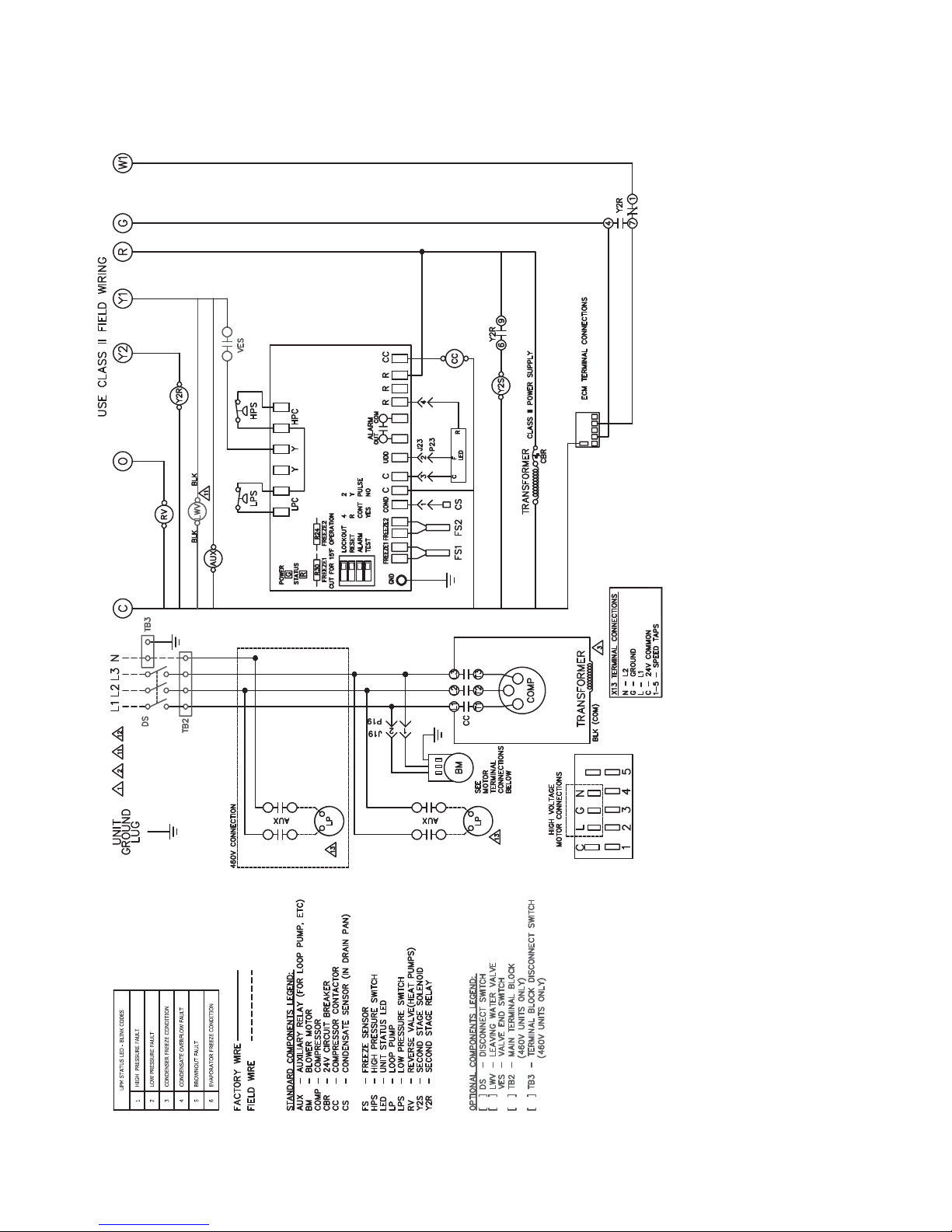
NOTES:
1. SEE UNIT NAMEPLATE FOR ELECTRICAL RATING.
2. ALL FIELD WIRING MUST BE IN ACCORDANCE WITH NEC-NFPA #70, COPPER CONDUCTORS ONLY.
3. 208/230V UNITS ARE FACTORY WIRED FOR 230V OPERATION. FOR 208V OPERATION, REMOVE LEAD FROM 240 TERMINAL
AND CONNECT IT TO 208. CAP ALL UNUSED TERMINALS.
4. UPM-1 INCLUDES BUILT IN: 270-300 SECOND RANDOM START
300 SECOND DELAY ON BREAK
120 SECOND LOW PRESSURE BYPASS
5. “TEST” DIP SWITCH REDUCES DELAYS TO 10 SEC WHEN SET TO YES. MUST BE SET TO “NO” FOR NORMAL OPERATION.
6. “FREEZE SENSOR” ON CONDENSER WILL OPERATE AT 26 F BY DEFAULT, IF 15 F OPERATION IS REQUIRED JUMPER R30 MUST BE CUT.
IF FREEZE SENSOR IS NOT INSTALLED A JUMPER SHALL BE INSTALLED BETWEEN THE FREEZE1 OR FREEZE2 SENSOR TERMINALS.
7. “ALARM OUTPUT” DIP SWITCH MUST BE SET TO “PULSE” IF BLINKING T-STAT SERVICE LIGHT IS DESIRED.
8. DEFAULT SETTINGS FOR COMPLETE C BOARD FROM FACTORY SHOWN.
9. ALARM OUTPUT IS NORMALLY OPEN (NO) DRY CONTACT. IF 24 VAC IS NEEDED, CONNECT R TO ALR-COM TERMINAL. 24 VAC WILL BE SENSED
ON THE ALR-OUT WHEN THE UNIT IS IN ALARM CONDITION. OUTPUT WILL BE PULSED IF PULSE IS SELECTED.
10. FACTORY-MOUNTED LOOP PUMP OR TWO-WAY WATER VALVE. BOTH DEVICES WILL NOT BE PRESENT IN THE SAME UNIT.
11. PUMP MOTOR IS WIRED BETWEEN LINE AND NEUTRAL FOR 308-460VAC UNITS. FOR 208/230VAC UNITS PUMP MOTOR IS WIRED BETWEEN LINES.
COMPLETE C
ECM – ELECTRONICALLY COMMUTATED MOTOR
SEE NOTES 5-9
Fig. 14 — Constant Torque Motor, Three Phase/Single Stage Two Step, Complete C Control
17
Page 18
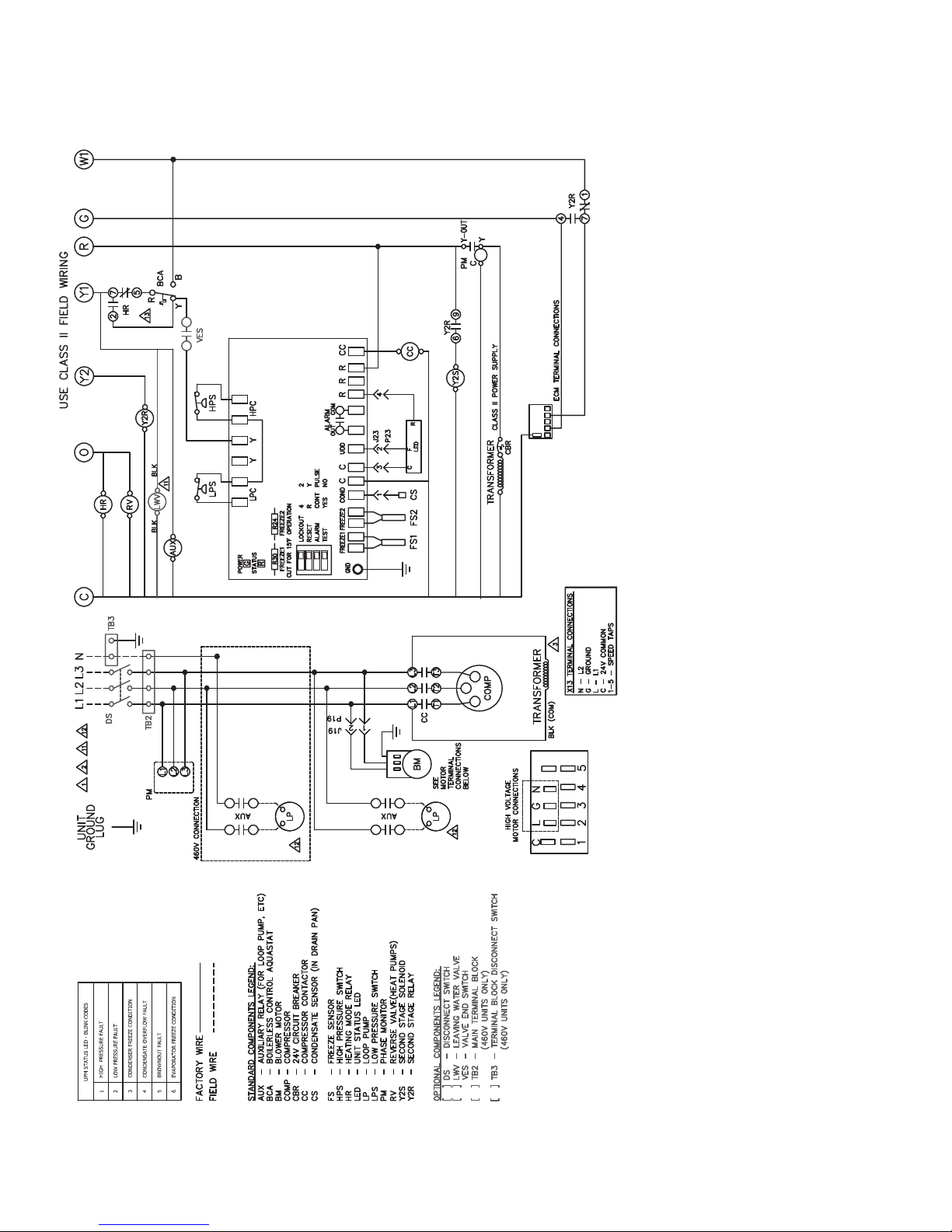
NOTES:
1. SEE UNIT NAMEPLATE FOR ELECTRICAL RATING.
2. ALL FIELD WIRING MUST BE IN ACCORDANCE WITH NEC-NFPA #70, COPPER CONDUCTORS ONLY.
3. 208/230V UNITS ARE FACTORY WIRED FOR 230V OPERATION. FOR 208V OPERATION, REMOVE LEAD FROM 240 TERMINAL
AND CONNECT IT TO 208. CAP ALL UNUSED TERMINALS.
4. UPM-1 INCLUDES BUILT IN: 270-300 SECOND RANDOM START
300 SECOND DELAY ON BREAK
120 SECOND LOW PRESSURE BYPASS
5. “TEST” DIP SWITCH REDUCES DELAYS TO 10 SEC WHEN SET TO YES. MUST BE SET TO “NO” FOR NORMAL OPERATION.
6. “FREEZE SENSOR” ON CONDENSER WILL OPERATE AT 26 F BY DEFAULT, IF 15 F OPERATION IS REQUIRED JUMPER R30 MUST BE CUT.
IF FREEZE SENSOR IS NOT INSTALLED A JUMPER SHALL BE INSTALLED BETWEEN THE FREEZE1 OR FREEZE2 SENSOR TERMINALS.
7. “ALARM OUTPUT” DIP SWITCH MUST BE SET TO “PULSE” IF BLINKING T-STAT SERVICE LIGHT IS DESIRED.
8. DEFAULT SETTINGS FOR DELUXE D BOARD FROM FACTORY SHOWN.
9. ALARM OUTPUT IS NORMALLY OPEN (NO) DRY CONTACT. IF 24 VAC IS NEEDED, CONNECT R TO ALR-COM TERMINAL. 24 VAC WILL BE SENSED
ON THE ALR-OUT WHEN THE UNIT IS IN ALARM CONDITION. OUTPUT WILL BE PULSED IF PULSE IS SELECTED.
10. FACTORY-MOUNTED LOOP PUMP OR TWO-WAY WATER VALVE. BOTH DEVICES WILL NOT BE PRESENT IN THE SAME UNIT.
11. PUMP MOTOR IS WIRED BETWEEN LINE AND NEUTRAL FOR 308-460VAC UNITS. FOR 208/230VAC UNITS PUMP MOTOR IS WIRED BETWEEN LINES.
12. BCA CONTACTS R-Y OPEN ON DROP IN WATER TEMPERATURE AND R-B CLOSE.
DELUXE D
SEE NOTES 5-9
Fig. 15 — Constant Torque Motor, Three Phase/Single Stage Two Step, Deluxe D Control
18
Page 19
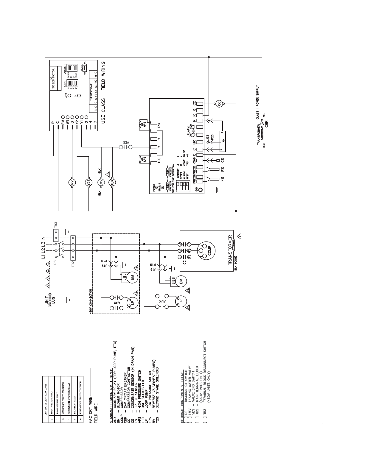
NOTES:
1. SEE UNIT NAMEPLATE FOR ELECTRICAL RATING.
2. ALL FIELD WIRING MUST BE IN ACCORDANCE WITH NEC-NFPA #70, COPPER CONDUCTORS ONLY.
3. 208/230V UNITS ARE FACTORY WIRED FOR 230V OPERATION. FOR 208V OPERATION, REMOVE LEAD
FROM 240 TERMINAL AND CONNECT IT TO 208. CAP ALL UNUSED TERMINALS.
4. UPM-1 INCLUDES BUILT IN: 270-300 SECOND RANDOM START
300 SECOND DELAY ON BREAK
120 SECOND LOW PRESSURE BYPASS
5. “TEST” DIP SWITCH REDUCES DELAYS TO 10 SEC WHEN SET TO YES. MUST BE SET TO “NO” FOR NORMAL OPERATION.
6. “FREEZE SENSOR” ON CONDENSER WILL OPERATE AT 26 F BY DEFAULT, IF 15 F OPERATION IS REQUIRED JUMPER R30 MUST BE CUT.
IF FREEZE SENSOR IS NOT INSTALLED A JUMPER SHALL BE INSTALLED BETWEEN THE FREEZE1 OR FREEZE2 SENSOR TERMINALS.
7. “ALARM OUTPUT” DIP SWITCH MUST BE SET TO “PULSE” IF BLINKING T-STAT SERVICE LIGHT IS DESIRED.
8. DEFAULT SETTINGS FOR COMPLETE C BOARD FROM FACTORY SHOWN.
9. ALARM OUTPUT IS NORMALLY OPEN (NO) DRY CONTACT. IF 24 VAC IS NEEDED, CONNECT R TO ALR-COM TERMINAL. 24 VAC WILL BE SENSED
ON THE ALR-OUT WHEN THE UNIT IS IN ALARM CONDITION. OUTPUT WILL BE PULSED IF PULSE IS SELECTED.
10. FACTORY-MOUNTED LOOP PUMP OR TWO-WAY WATER VALVE. BOTH DEVICES WILL NOT BE PRESENT IN THE SAME UNIT.
11. PUMP MOTOR IS WIRED BETWEEN LINE AND NEUTRAL FOR 380-460VAC UNITS. FOR 208/230VAC UNITS PUMP MOTOR IS WIRED BETWEEN LINES.
12. EON MOTOR IS WIRED BETWEEN LINE AND NEUTRAL FOR 380-460VAC UNITS. FOR 208/230VAC UNITS EON MOTOR IS WIRED BETWEEN LINES.
COMPLETE C
SEE NOTES 5-9
19
Fig. 16 — Constant Airflow ECM Motor, Three Phase/Single Stage Two Step, Complete C Control
Page 20
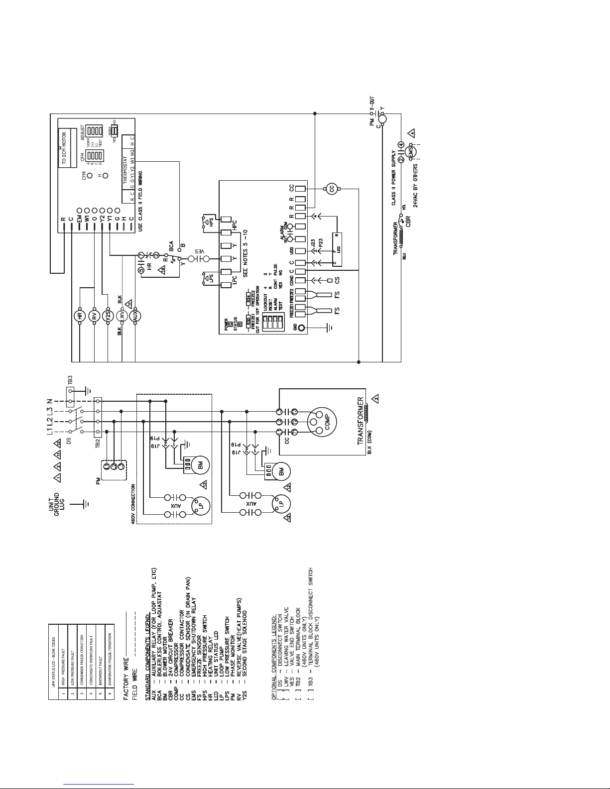
NOTES:
1. SEE UNIT NAMEPLATE FOR ELECTRICAL RATING.
2. ALL FIELD WIRING MUST BE IN ACCORDANCE WITH NEC-NFPA #70, COPPER CONDUCTORS ONLY.
3. 208/230V UNITS ARE FACTORY WIRED FOR 230V OPERATION. FOR 208V OPERATION, REMOVE LEAD
FROM 240 TERMINAL AND CONNECT IT TO 208. CAP ALL UNUSED TERMINALS.
4. FOR ALTERNATIVE EMS COIL VOLTAGES CONSULT FACTORY.
5. UPM-1 INCLUDES BUILT IN: 270-300 SECOND RANDOM START
300 SECOND DELAY ON BREAK
120 SECOND LOW PRESSURE BYPASS
6. “TEST” DIP SWITCH REDUCES DELAYS TO 10 SEC WHEN SET TO YES. MUST BE SET TO “NO” FOR NORMAL OPERATION.
7. “FREEZE SENSOR” ON CONDENSER WILL OPERATE AT 26 F BY DEFAULT, IF 15 F OPERATION IS REQUIRED JUMPER R30 MUST BE CUT.
IF FREEZE SENSOR IS NOT INSTALLED A JUMPER SHALL BE INSTALLED BETWEEN THE FREEZE1 OR FREEZE2 SENSOR TERMINALS.
8. “ALARM OUTPUT” DIP SWITCH MUST BE SET TO “PULSE” IF BLINKING T-STAT SERVICE LIGHT IS DESIRED.
9. DEFAULT SETTINGS FOR DELUXE D BOARD FROM FACTORY SHOWN.
10. ALARM OUTPUT IS NORMALLY OPEN (NO) DRY CONTACT. IF 24 VAC IS NEEDED, CONNECT R TO ALR-COM TERMINAL. 24 VAC WILL BE SENSED
ON THE ALR-OUT WHEN THE UNIT IS IN ALARM CONDITION. OUTPUT WILL BE PULSED IF PULSE IS SELECTED.
11. FACTORY-MOUNTED LOOP PUMP OR TWO-WAY WATER VALVE. BOTH DEVICES WILL NOT BE PRESENT IN THE SAME UNIT.
12. PUMP MOTOR IS WIRED BETWEEN LINE AND NEUTRAL FOR 380-460VAC UNITS. FOR 208-230VAC UNITS PUMP MOTOR IS WIRED BETWEEN LINES.
13. EON MOTOR IS WIRED BETWEEN LINE AND NEUTRAL FOR 380-460VAC UNITS. FOR 208/230VAC UNITS WON MOTOR IS WIRED BETWEEN LINES.
14. BCA CONTACTS R-Y OPEN ON DROP IN WATER TEMPERATURE AND R-B CLOSE.
DELUXE D
20
Fig. 17 — Constant Airflow ECM Motor, Three Phase/Single Stage Two Step, Deluxe D Control
Page 21
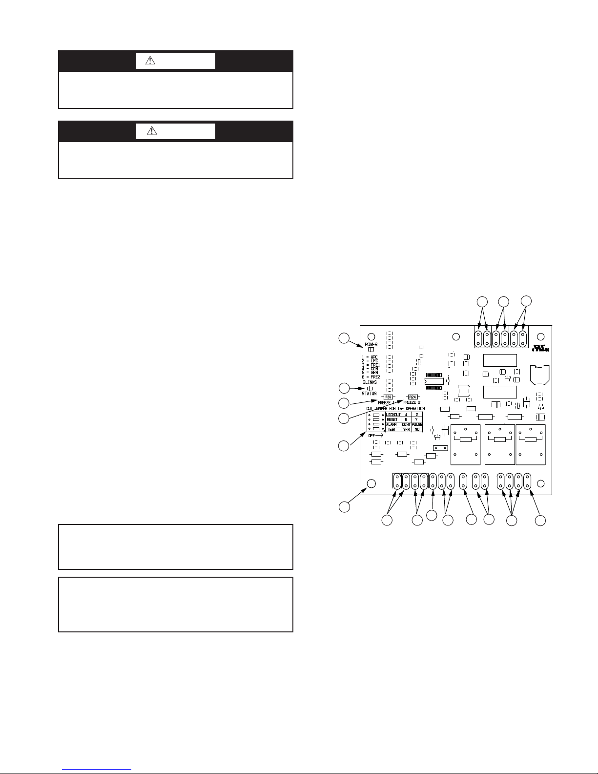
Step 9 — Wire Field Controls
1
2
3
4
5
6
7
9
10
11
1213
17
14
15
16
8
WARNING
To avoid possible injury or death due to electrical shock,
open the power supply disconnect switch and secure it in
an open position during installation.
CAUTION
Operating the unit with improper line voltage or with
excessive phase imbalance is hazardous to the unit and
constitutes abuse and is not covered under warranty.
All field wiring must comply with local and national fire,
safety and electrical codes. Power to the unit must be within the
operating voltage range indicated on the unit’s nameplate.
Properly sized fuses or HACR circuit breakers must be installed for branch circuit protection. See unit nameplate for
maximum fuse or breaker size. The unit is provided with a concentric knock-out for attaching common trade sizes of conduit,
route power supply wiring through this opening. Always connect the ground lead to the grounding lug provided in the control box and power leads to the line side of compressor contactor as indicated on the wiring diagram.
CONSTANT TORQUE MOTORS (ECM) — For installations where the efficiency of an electronically commutated
brushless DC motor (ECM) motor is required, but the features
of a constant airflow motor are not required and comes standard with the constant torque ECM motor option. These motors feature up to 90% thermal efficiency combined with a flatter fan curve than a PSC motor and simple operation.
These motors are provided with 5 speed taps to allow for a
wide range of airflow and external static options. To change a
speed tap follow the instructions below:
1. Disconnect power to the heat pump.
2. Remove the blower access panel.
3. Remove the speed tap wire from the terminal it is currently connected to and connect it to the terminal desired.
Refer to Tables 7 and 8 for constant torque motor performance tables for heat pump blower performance with the constant torque motor option.
SAFETY DEVICES AND COMPLETE C CONTROL —
Each unit is factory provided with a Complete C board controller that controls the compressor operation and monitors the
safety.
• Low-pressure switch located in the unit refrigerant suction line and wired across terminals LPC1 and LPC2 on
the Complete C Board.
• Complete C Board Dry Contacts are Normally Open
(NO).
• Water side freeze protection sensor, mounted close to
condensing water coil, monitors refrigerant temperature
between condensing water coil and thermal expansion
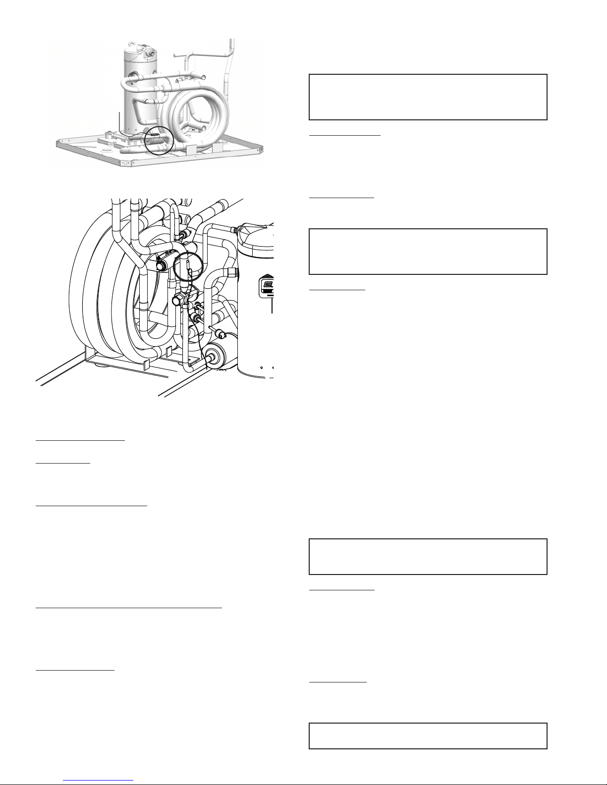
valve. See Fig. 19. If temperature drops below or
remains at freeze limit trip for 30 seconds, the controller
will shut down the compressor and enter into a soft lockout condition. The default freeze limit trip is 30 F, however this can be changed to 15 F by cutting the R30 or
Freeze1 resistor located on top of DIP switch SW1.
Refer to Fig. 18 item 3 for resistor location.
• Evaporator freeze protection sensor, mounted between
the thermal expansion device and the evaporator, monitors refrigerant temperature between the evaporator coil
and thermal expansion valve. See Fig. 20. If temperature
drops below or remains at freeze limit trip for 30 seconds, the controller will shut down the compressor and
enter into a soft lockout condition. The default freeze
limit trip is 30 F.
• The condensate overflow protection sensor is located in
the drain pan of the unit and connected to the ‘COND’
terminal on the Complete C board.
IMPORTANT: If the thermostat is provided with a malfunction light powered off of the common (C) side of the
transformer, a jumper between R and COM terminal of
ALR contacts must be made.
IMPORTANT: If the thermostat is provided with a malfunction light powered off of the hot (R) side of the transformer, then the thermostat malfunction light connection
should be connected directly to the (ALR) contact on the
unit’s Complete C board.
If the unit is being connected to a thermostat with a malfunction light, this connection is made at the unit malfunction
output or relay. See to Fig. 18.
Safety controls include the following:
• High-pressure switch located in the refrigerant discharge
line and wired across the HPC terminals on the Complete
C Board.
21
1—Board Power Indicator
2—Control C Status LED Indicator
3—Water Coil Freeze Protection Tem-
4—Air Coil Freeze Protection Tempera-
5—Control C Board Settings
6—Water Coil Freeze Connection
7—Air Coil Freeze Connection
8—LED Status-Diagnostic Connection
9—24VAC Power Input
10 — Compressor Contact Output
11 — High Pressure Switch Connection
12 — Call for Compressor Y1
13 — Low Pressure Switch Connection
14 — 24VAC Power Common
15 — Condensate Overflow Sensor
16 — Dry Contact
17 — Control C Ground Standoff
perature Selection [R30]
ture Selection
Fig. 18 — Complete C Control Board
Page 22
blink code explanation. The remote device must have a malfunction detection capability when the Complete C board is set
to PULSE.
IMPORTANT: If 24 VAC output is needed R must be
wired to ALR-COM terminal; 24 VAC will be available to
the ALR-OUT terminal when the unit is in the alarm condition.
Fig. 19 — Water Freeze Protection Sensor
Location
Fig. 20 — No Freeze Protection Sensor
The C Board includes the following features:
Anti-short Cycle Time
— A 5-minute delay on break timer
prevents compressor short cycling.
Random Start
— Each controller has a unique random start
delay ranging from 270 to 300 seconds to reduce the chances
of multiple units simultaneously starting after initial power up
or after a power interruption, creating a large electrical spike.
Low Pressure Bypass Timer
— If the compressor is running
and the low-pressure switch opens, the controller will keep the
compressor ON for 120 seconds. If, after 120 seconds the lowpressure switch remains open, the controllers will shut down
the compressor and enter a soft lockout. The compressor will
not be energized until the low-pressure switch closes and the
anti-short cycle time delay expires. If the low-pressure switch
opens 2 to 4 times in 1 hour, the unit will enter a hard lockout.
In order to exit hard lockout power to the unit would need to be
reset.
Brownout/Surge/Power Interruption Protection
— The
brownout protection in the Complete C board will shut down
the compressor if the incoming power falls below 18 VAC. The
compressor will remain OFF until the voltage is above 18 VAC
and ANTI-SHORT CYCLE TIMER (300 seconds) times out.
The unit will not go into a hard lockout.
Malfunction Output
— Alarm output is Normally Open (NO)
dry contact. If pulse is selected the alarm output will be pulsed.
The fault output will depend on the DIP switch setting for
ALARM. If it is set to CONST, a constant signal will be produced to indicate a fault has occurred and the unit requires inspection to determine the type of fault. If it is set to PULSE, a
pulse signal is produced and a fault code is detected by a remote device indicating the fault. See LED Fault Indication for
LED Annunciator
— This LED kit provides a quick visual indication of whether or not a heat pump is energized and if it has
locked out on a fault. The LED kit is mounted to the electrical
corner post of the heat pump and employs high intensity LEDs
for better visibility. The LED kit will exactly mirror the LED
blink codes on the Complete C board.
Test DIP Switch
— A test DIP switch is provided to reduce all
time delays settings to 10 seconds during troubleshooting or
verification of unit operation.
IMPORTANT: Operation of unit in test mode can lead to
accelerated wear and premature failure of components. The
"TEST" switch must be set back to "NO" after troubleshooting or servicing.
Freeze Sensor
— The default setting for the freeze limit trip is
30 F (sensor number 1); however this can be changed to 15 F
by cutting the R24 resistor located on top of the DIP switch
SW1. Since freeze sensor 2 is dedicated to monitor the evaporator coil it is recommended to leave the factory default setting
on the board. The Complete C controller will constantly monitor the refrigerant temperature with the sensor mounted close to
the condensing water coil between the thermal expansion valve
and water coil. If temperature drops below or remains at the
freeze limit trip for 30 seconds, the controller will shut the
compressor down and enter into a soft lockout condition. Both
the status LED and the Alarm contact will be active. The LED
will flash three times the code associated with this alarm condition. If this alarm occurs 2 times (or 4 if DIP switch is set to 4)
within an hour the Complete C controller will enter into a hard
lockout condition. It will constantly monitor the refrigerant
temperature with the sensor mounted close to the evaporator
between the thermal expansion valve and evaporator coil. If
temperature drops below or remains at the freeze limit trip for
30 seconds, the controller will shut the compressor down and
enter into a soft lockout condition. Both the status LED and the
Alarm contact will be active. The LED will flash three times
the code associated with this alarm condition. If this alarm occurs 2 times (or 4 if DIP switch is set to 4) within an hour the
controller will enter into a hard lockout condition.
IMPORTANT: Freeze sensor will not guard against loss of
water. Flow switch is recommended to prevent unit from
running if water flow is lost or reduced.
Intelligent Reset
— If a fault condition is initiated, the 5 minute delay on break time period is initiated and the unit will restart after these delays expire. During this period the fault LED
will indicate the cause of the fault. If the fault condition still exists or occurs 2 or 4 times (depending on 2 or 4 setting for
Lockout DIP switch) before 60 minutes, the unit will go into a
hard lockout and requires a manual lockout reset. A single condensate overflow fault will cause the unit to go into a hard lockout immediately, and will require a manual lockout reset.
Lockout Reset
— A hard lockout can be reset by turning the
unit thermostat off and then back on when the “RESET” DIP
switch is set to “Y” or by shutting off unit power at the circuit
breaker when the “RESET” DIP switch is set to “R.”
IMPORTANT: The blower motor will remain active during a lockout condition.
22
Page 23
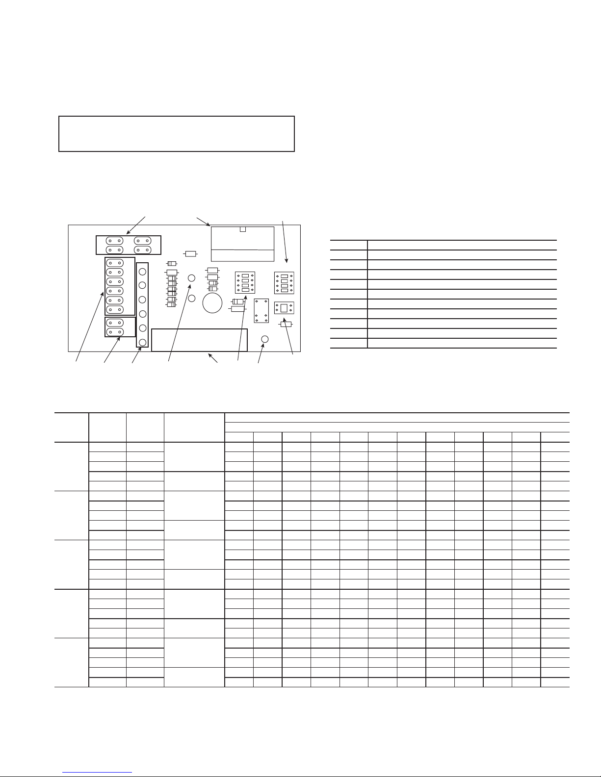
Operate ECM Interface Board — In addition to pro-
RR
C1
C2
10
EM
W1
O
Y2
Y1
G
H
C
W2
W1
O
Y2
Y1
G
CFM
H
CFM
ADJUST
A
B
C
D
NORM
[+]
[-]
TEST
HGRH
YES
NO
HGRH
J01
R
C
G
O
Y1 Y2 W1 W2 H C
1
3
98
7
6
5
2
4
11
viding a connecting point for thermostat wiring, the interface
board also translates thermostat inputs into control commands
for the Electronic Commutated Motor (ECM) DC fan motor
and provides thermostat signlas to unit’s Complete C board.
The thermostat connections and their functions are shown in
Fig. 21.
IMPORTANT: CFM LED is an approximation. Utilize
conventional Test and Balance equipment for accurate
airflow measurement.
The CFM count indicator (See Fig. 21, item 6) blinks to indi-
cate approximate airflow in CFM and may flicker when unit is
off. Each blink of the LED represent approximately 100 CFM
of air delivery so if the LED blinks 12 times, pauses, blinks 12
times, etc. the blower is delivering approximately 1200 CFM.
THERMOSTAT OUTPUTS
Y1 First Stage Compressor Operation
Y2 Second Stage Compressor Operation
G Fan
O Reversing Valve (energized in cooling)
W1 Auxiliary Electric Heat (runs with compressor)
EM/W2 Emergency Heat (electric heat only)
NC Transformer 24 VAC Common (extra connection)
C1 Transformer 24 VAC Common (primary connection)
R Transformer 24 VAC Hot
H Dehumidification Mode
1 Motor harness plug
2 Blower CFM adjustment
3 Motor settings
4 Dehumidification indication
5 Thermostat digital contact inputs
6 CFM count indicator
7 Thermostat input status indication
8 Reheat digital outputs
9 Thermostat outputs
10 24 VAC
11 Dehumidification method selector
Fig. 21 — ECM Interface Board Physical Layout
Table 7 — Constant Torque Motor Blower Performance Data
50PTH,
PTV
UNITS
024
036
048
060
070
——Operation Not Recommended
FL — Full Load
PL — Part Load
FAN
SPEED
LEGEND
RATED
AIRFLOW
(Cfm)
5950
4
3
2
1
5
4
3
2
1
5
4
3
2
1
5
4
3
2
1
5
4
3
2
1
825 1,072 1,018 966 915 866 818 772 727
725 976 920 867 815 766 719 674 631
650
500 829 750 676 610 551 498 451 412
1300
1100 1,425 1,326 1,250 1,191 1,143 1,100 1,056 1,006 942 860
950 1,354 1,233 1,138 1,063 1,002 950 901 850 791 719
800
750 1,213 1,084 976 886 812 750 698 653 612 573
1800
1600 1,774 1,738 1,703 1,669 1,635 1,600 1,562 1,521 1,475 1,423
1400 1,565 1,526 1,493 1,463 1,432 1,400 1,363 1,319 1,265 1,199
1300
1100 1,425 1,326 1,250 1,191 1,143 1,100 1,056 1,006 942 860
2200
2000 2,170 2,135 2,100 2,066 2,033 2,000 1,968 1,937 1,907 1,877 1,848 1,819
1800 1,942 1,914 1,886 1,858 1,829 1,800 1,770 1,741 1,710 1,680 1,649 1,617
1600
1400 1,561 1,520 1,483 1,451 1,423 1,400 1,381 1,366 1,356 1,350 1,349 1,352
2500
2350 2,566 2,529 2,489 2,446 2,399 2,350 2,298 2,242 2,184 2,122 2,057 1,990
2100 2,256 2,230 2,202 2,171 2,137 2,100 2,060 2,017 1,971 1,922 1,871 1,816
1850
1600 1,766 1,728 1,693 1,660 1,629 1,600 1,573 1,548 1,526 1,505 1,486 1,470
FAC TORY
PL/Fan Only
PL/Fan Only
PL/Fan Only
PL/Fan Only
PL/Fan Only
SETTING
FL
FL
FL
FL
FL
AIRFLOW (Cfm)
External Static Pressure (in. wg)
0.100.200.300.400.500.600.700.800.901.001.101.20
1,1541,1171,0771,034988938886830————
906 844 785 730 678 630 585 544
1,506 1,469 1,430 1,390 1,347 1,300 1,249 1,193 1,130 1,061
1,294 1,157 1,041 946 866 800 744 696 653 611
1,950 1,912 1,880 1,852 1,826 1,800 1,771 1,737 1,695 1,644
1,506 1,469 1,430 1,390 1,347 1,300 1,249 1,193 1,130 1,061
2,476 2,403 2,338 2,283 2,237 2,200 2,172 2,153 2,142 2,141 2,149 2,166
1,766 1,729 1,693 1,660 1,629 1,600 1,573 1,548 1,526 1,505 1,487 1,470
2,723 2,671 2,622 2,578 2,537 2,500 2,467 2,437 2,412 2,390 2,372 2,358
2,004 1,975 1,945 1,915 1,883 1,850 1,816 1,781 1,745 1,708 1,669 1,630
23
————
————
————
————
——
——
——
——
——
——
——
——
——
——
Page 24
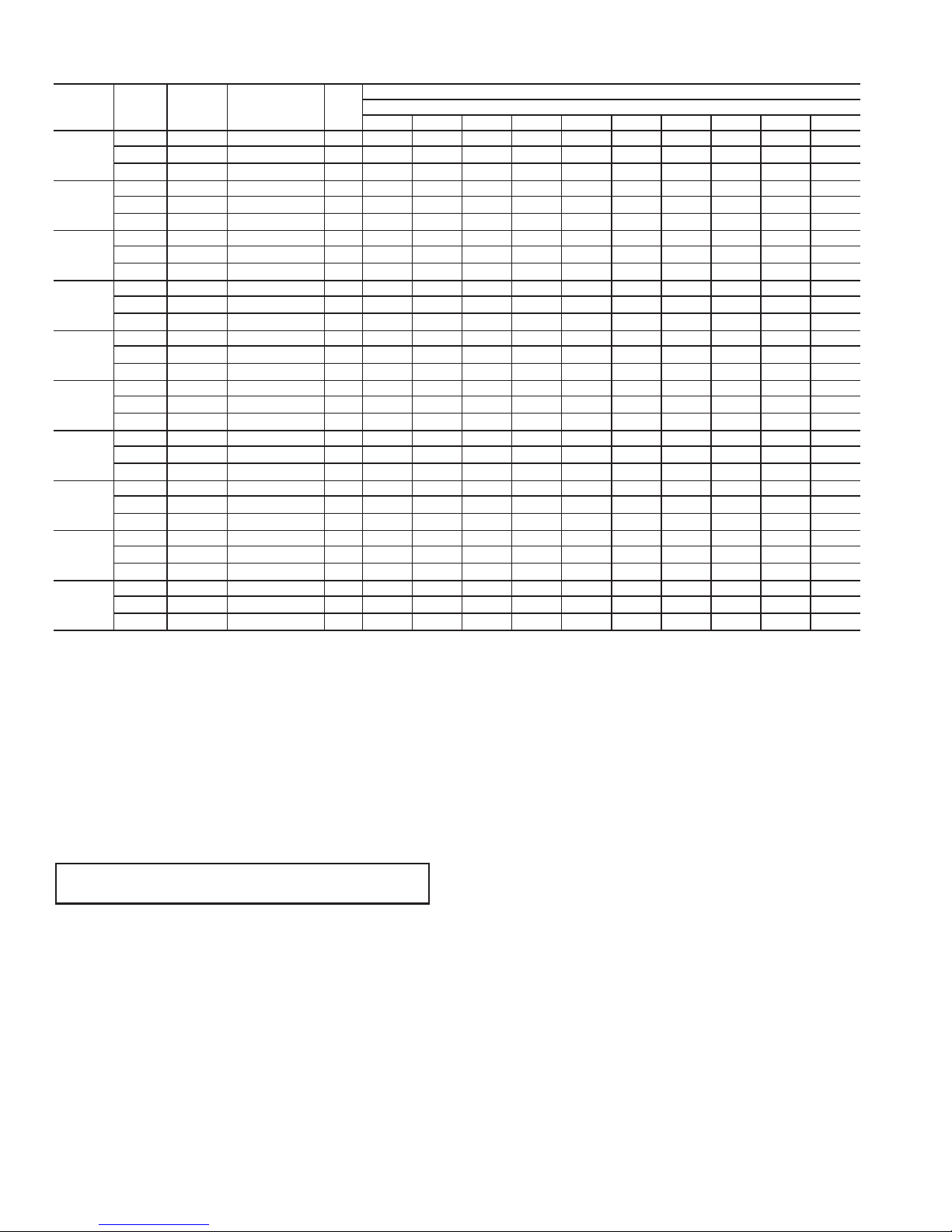
Table 8 — ECM Constant CFM Motor Blower Performance Data
50PTH,
PTV
UNITS
024
PA RT
LOAD
024
FULL
LOAD
036
PA RT
LOAD
036
FULL
LOAD
048
PA RT
LOAD
048
FULL
LOAD
060
PA RT
LOAD
060
FULL
LOAD
070
PA RT
LOAD
070
FULL
LOAD
FAN
SPEED
High 725 + A 725 725 725 725 725 725 725 725 — —
Med
Low
High 950 + A 950 950 950 950 950 950 950 950 — —
Med
Low
High 950 + A 950 950 950 950 950 950 950 950 950 950
Med
Low
High 1300 + A 1,300 1,300 1,300 1,300 1,300 1,300 1,300 1,300 1,300 1,300
Med
Low
High 1400 + A 1,400 1,400 1,400 1,400 1,400 1,400 1,400 1,400 1,400 1,400
Med
Low
High 1800 + A 1,800 1,800 1,800 1,800 1,800 1,800 1,800 1,800 1,800 1,800
Med
Low
High 1800 + A 1,800 1,800 1,800 1,800 1,800 1,800 1,800 1,800 1,800 1,800
Med
Low
High 2200 + A 2,200 2,200 2,200 2,200 2,200 2,200 2,200 2,200 2,200 2,200
Med
Low
High 2100 + A 2,100 2,100 2,100 2,100 2,100 2,100 2,100 2,100 2,100 2,100
Med
Low
High 2500 + A 2,500 2,500 2,500 2,500 2,500 2,500 2,500 2,500 2,500 2,500
Med
Low
RATED
AIRFLOW
(Cfm)
650 Normal
500 -
825 Normal
725 -
800 Normal
750 -
1100 Normal
950 -
1300 Normal
1100 -
1600 Normal
1400 -
1600 Normal
1400 -
2000 Normal
18000 -
1850 Normal
1600 -
2350 Normal
2100 -
ADJUSTMENT TAP
0.100.200.300.400.500.600.700.800.901.00
A
650 650 650 650 650 650 650 650 — —
A
500 500 500 500 500 500 500 500 — —
A
825 825 825 825 825 825 825 825 — —
A
725 725 725 725 725 725 725 725 — —
A
800 800 800 800 800 800 800 800 800 800
A
750 750 750 750 750 750 750 750 750 750
A
1,100 1,100 1,100 1,100 1,100 1,100 1,100 1,100 1,100 1,100
A
950 950 950 950 950 950 950 950 950 950
A
1,300 1,300 1,300 1,300 1,300 1,300 1,300 1,300 1,300 1,300
A
1,100 1,100 1,100 1,100 1,100 1,100 1,100 1,100 1,100 1,100
A
1,600 1,600 1,600 1,600 1,600 1,600 1,600 1,600 1,600 1,600
A
1,400 1,400 1,400 1,400 1,400 1,400 1,400 1,400 1,400 1,400
A
1,600 1,600 1,600 1,600 1,600 1,600 1,600 1,600 1,600 1,600
A
1,400 1,400 1,400 1,400 1,400 1,400 1,400 1,400 1,400 1,400
A
2,000 2,000 2,000 2,000 2,000 2,000 2,000 2,000 2,000 2,000
A
1,800 1,800 1,800 1,800 1,800 1,800 1,800 1,800 1,800 1,800
A
1,850 1,850 1,850 1,850 1,850 1,850 1,850 1,850 1,850 1,850
A
1,600 1,600 1,600 1,600 1,600 1,600 1,600 1,600 1,600 1,600
A
2,350 2,350 2,350 2,350 2,350 2,350 2,350 2,350 2,350 2,350
A
2,100 2,100 2,100 2,100 2,100 2,100 2,100 2,100 2,100 2,100
LEGEND
— — Operation Not Recommended
PRE-START-UP
System Checkout —
and before energizing the unit, the following system checks
should be made prior to initial start-up:
1. Verify that the supply voltage to the heat pump is in a
ccordance with the nameplate ratings.
2. Make sure that all electrical connections are tight and
secure.
3. Check the electrical fusing and wiring for the correct size.
IMPORTANT: Ensure cabinet and electrical box are
properly grounded.
4. Verify that the low voltage wiring between the thermostat
and the unit is correct.
5. Verify that the water piping is complete and correct.
6. Check that the water flow is correct, and adjust if
necessary.
7. Check the blower for free rotation, and that it is secured to
the shaft.
8. Verify that vibration isolation has been provided.
9. Unit is serviceable. Be certain that all access panels are
secured in place.
10. Always check incoming line voltage power supply and
secondary control voltage for adequacy. Transformer primaries are dual tapped for 208 and 230 volts. Connect the
After completing the installation,
AIRFLOW (Cfm)
External Static Pressure (in. wg)
appropriate tap to ensure a minimum of 18 volts secondary control voltage. 24 volts is ideal for best operation.
11. Long length thermostat and control wiring leads may create voltage drop. Increase wire gauge or up-size transformers may be required to ensure minimum secondary
voltage supply.
12. The following guidelines are recommended for wiring
between a thermostat and the unit: 18 gage up to 60 ft,
16 gage up to 100 ft and 14 gage up to 140 ft.
13. Do not apply additional controlled devices to the control
circuit power supply without consulting the factory. Doing so may void equipment warranties.
14. Check with all code authorities on requirements involving condensate disposal/over flow protection criteria.
AIR COIL — To obtain maximum performance, clean the air
coil before starting the unit. A 10% solution of dishwasher
detergent and water is recommended for both sides of the coil.
Rinse thoroughly with water.
24
Page 25
START-UP
Use the procedure outlined below to initiate proper unit
start-up.
NOTE: This equipment is designed for indoor installation
only. Set the thermostat to the highest setting.
Operating Limits
ENVIRONMENT — This equipment is designed for indoor
installation only. Extreme variations in temperature, humidity
and corrosive water or air will adversely affect the unit performance, reliability and service life.
POWER SUPPLY — A voltage variation of ± 10% of nameplate utilization voltage is acceptable.
UNIT STARTING CONDITIONS — Units start and operate
in an ambient temperature of 45 F with entering-air temperature at 50 F, entering-water temperature at 60 F and with both
air and water at the flow rates used.
NOTE: These operating limits are not normal or continuous
operating conditions. Assume that such a start-up is for the
purpose of bringing the building space up to occupancy temperature. See Table 9 for operating limits.
WARNING
When the disconnect switch is closed, high voltage is present in some areas of the electrical panel. Exercise caution
when working with the energized equipment. Failure to
heed this warning may result in personal injury.
1. Restore power to system.
2. Turn thermostat fan position to ON. Blower should start.
3. Balance airflow at registers.
4. Adjust all valves to the full open position and turn on the
line power to all heat pump units.
5. Operate unit in the cooling cycle. Refer to Table 9 for unit
operating limits.
NOTE: Three factors determine the operating limits of a unit:
(1) entering air temperature, (2) water temperature and (3)
ambient temperature. Whenever any of these factors are at a
minimum or maximum level, the other two factors must be at a
normal level to ensure proper unit operation.
Table 9 — Operating Limits
AIR LIMITS
Minimum Ambient Air Temperature F 50 50
Maximum Ambient Air Temperature F 100 100
Minimum Evaporator Entering Air db/wb F 68/57 68/57
Rated Air Coil Entering Air db/wb F 80/67 80/67
Maximum Evaporator Entering Air db/wb F 95/85 98/85
Minimum Water Coil Entering Fluid
Temperature F
Water Loop Typical Coil Entering Fluid
Range Temperature F
Maximum Water Coil Entering Fluid
Temperature F
Minimum Ambient Air Temperature F 50 40
Maximum Ambient Air Temperature F 100 85
Minimum Evaporator Entering Air db F 50 50
Rated Air Coil Entering Air F 68 68
Maximum Evaporator Entering Air db F 80 80
Normal Water Coil Entering Fluid Range F 50-80 25-80*
Minimum Water Coil Entering Fluid F 50 20*
LEGEND
db — Dry Bulb
wb — Wet Bulb
*Antifreeze solution is required at these fluid temperatures.
COOLING
HEATING
STANDARD
UNIT
50 50
70/90 70/90
110 110
EXTENDED
RANGE
OPTION
Scroll Compressor Rotation — It is important to be
certain the compressor is rotating in the proper direction. To
determine whether or not the compressor is rotating in the
proper direction:
1. Connect service gages to suction and discharge pressure
fittings.
2. Energize the compressor.
3. The suction pressure should drop and the discharge
pressure should rise, as is normal on any start-up.
If the suction pressure does not drop and the discharge
pressure does not rise to normal levels:
1. Turn off power to the unit. Install disconnect tag.
2. Reverse any two of the unit power leads.
3. Reapply power to the unit and verify pressures are correct.
The suction and discharge pressure levels should now move
to their normal start-up levels.
When the compressor is rotating in the wrong direction, the
unit makes more noise and does not provide cooling.
After a few minutes of reverse operation, the scroll compressor internal overload protection will open, thus activating
the unit lockout. This requires a manual reset. To reset, turn the
thermostat on and then off.
NOTE: There is a 5-minute time delay before the compressor
will start.
Unit Start-Up Cooling Mode
1. Adjust the unit thermostat to the warmest position.
Slowly reduce the thermostat position until the compressor activates.
2. Check for cool air delivery at unit grille a few minutes
after the unit has begun to operate.
3. Verify that the compressor is on and that the water flow
rate is correct by measuring pressure drop through the
heat exchanger using P/T plugs. See Table 10. Check the
elevation and cleanliness of the condensate lines; any
dripping could be a sign of a blocked line. Be sure the
condensate trap includes a water seal.
4. Check the temperature of both supply and discharge
water. If temperature is within range, proceed. If temperature is outside the range, check the cooling refrigerant
pressures. Contact Carrier Commercial Services or product management for acceptable temperature ranges.
5. Check air temperature drop across the coil when compressor is operating. Air temperature drop should be
between 15 and 25 F.
Table 10 — Water Temperature Change
through Heat Exchanger
WATER FLOW RATE (GPM)
For Closed Loop: Ground Source or
Cooling/Boiler Systems at 3 gpm/ton
For Open Loop: Ground Water Systems at
1.5 gpm/ton
COOLING
RISE (F)
Min Max Min Max
91248
20 26 10 17
HEATING
DROP (F)
Unit Start-Up Heating Mode
NOTE: Operate the unit in heating cycle after checking the
cooling cycle. Allow 5 minutes between tests for the pressure
or reversing valve to equalize.
1. Turn thermostat to lowest setting and set thermostat
switch to HEAT position.
2. Slowly turn the thermostat to a higher temperature until
the compressor activates.
3. Check for warm air delivery at the unit grille within a few
minutes after the unit has begun to operate.
4. Check the temperature of both supply and discharge
water. If temperature is within range, proceed. If temperature is outside the range, check the heating refrigerant
25
Page 26
pressures. Contact Carrier Commercial Services or product management for acceptable temperature ranges.
5. Once the unit has begun to run, check for warm air delivery at the unit grille.
6. Check air temperature rise across the coil when compressor is operating. Air temperature rise should be between
20 and 30 F after 15 minutes at load.
7. Check for vibration, noise and water leaks.
Flow Regulation — Flow regulation can be accom-
plished by two methods. Most water control valves have a flow
adjustment built into the valve. By measuring the pressure drop
through the unit heat exchanger, the flow rate can be determined. See Table 11. Adjust the water control valve until the
flow of 1.5 to 2 gpm is achieved. Since the pressure constantly
varies, two pressure gages may be needed in some
applications.
Table 11 — Coaxial Water Pressure Drop
UNIT 50PTH, PTV GPM
4.0 1.5 1.3 1.1 1.0
024
036
048
060,070
6.0 3.1 2.6 2.3 2.1
7.0 4.1 3.4 3.0 2.7
8.0 5.1 4.3 3.8 3.4
4.0 1.2 1.0 0.8 0.6
6.0 2.6 2.5 2.3 2.1
8.0 4.5 4.2 4.0 3.7
9.0 5.7 5.2 4.8 4.4
5.5 1.1 0.9 0.8 0.7
8.3 2.2 2.1 2.0 1.8
11.0 3.9 3.6 3.2 3.1
12.0 4.5 4.2 3.8 3.5
7.0 0.5 0.3 0.2 0.1
10.5 1.9 1.8 1.7 1.6
14.0 3.9 3.5 3.2 2.9
15.0 4.8 4.3 3.9 3.5
WATER TEMPERATURE (F)
30 F 50 F 70 F 90 F
Pressure Drop (psi)
An alternative method is to install a flow control device.
These devices are typically an orifice of plastic material designed to allow a specified flow rate that are mounted on the
outlet of the water control valve. Occasionally these valves
produce a velocity noise that can be reduced by applying some
back pressure. To accomplish this, slightly close the leaving
isolation valve of the well water setup.
WARNING
4. Shutting off the return valve that connects into the flush
cart reservoir will allow 50 psig surges to help purge air
pockets. This maintains the pump at 50 psig.
5. To purge, keep the pump at 50 psig until maximum
pumping pressure is reached.
6. Open the return valve to send a pressure surge through
the loop to purge any air pockets in the piping system.
7. A noticeable drop in fluid level will be seen in the flush
cart tank. This is the only indication of air in the loop.
NOTE: If air is purged from the system while using a
10 in. PVC flush tank, the level drop will only be 1 to
2 in. since liquids are incompressible. If the level drops
more than this, flushing should continue since air is still
being compressed in the loop. If level is less than 1 to
2 in., reverse the flow.
8. Repeat this procedure until all air is purged.
9. Restore power.
Antifreeze may be added before, during, or after the flushing process. However, depending on when it is added in the
process, it can be wasted. Refer to the Antifreeze section for
more detail.
Loop static pressure will fluctuate with the seasons. Pressures will be higher in the winter months than during the warmer months. This fluctuation is normal and should be considered
when charging the system initially. Run the unit in either
heating or cooling for several minutes to condition the loop to a
homogenous temperature.
When complete, perform a final flush and pressurize the
loop to a static pressure of 40 to 50 psig for winter months or
15 to 20 psig for summer months.
After pressurization, be sure to remove the plug from the
end of the loop pump motor(s) to allow trapped air to be
discharged and to ensure the motor housing has been flooded.
Be sure the loop flow center provides adequate flow through
the unit by checking pressure drop across the heat exchanger.
Compare the results to the data in Table 11.
Antifreeze — In areas where entering loop temperatures
drop below 40 F or where piping will be routed through areas
subject to freezing, antifreeze is needed.
Alcohols and glycols are commonly used as antifreeze
agents. Freeze protection should be maintained to 15 F below
the lowest expected entering loop temperature. For example, if
the lowest expected entering loop temperature is 30 F, the
leaving loop temperature would be 22 to 25 F. Therefore, the
freeze protection should be at 15 F (30 F – 15 F = 15 F).
To avoid possible injury or death due to electrical shock,
open the power supply disconnect switch and secure it in
an open position before flushing system.
Flushing — Once the piping is complete, units require final
purging and loop charging. A flush cart pump of at least 1.5 hp
is needed to achieve adequate flow velocity in the loop to purge
air and dirt particles from the loop. Flush the loop in both directions with a high volume of water at a high velocity. Follow the
steps below to properly flush the loop:
1. Verify power is off.
2. Fill loop with water from hose through flush cart before
using flush cart pump to ensure an even fill. Do not allow
the water level in the flush cart tank to drop below the
pump inlet line in order to prevent air from filling the line.
3. Maintain a fluid level in the tank above the return tee in
order to avoid air entering back into the fluid.
IMPORTANT: All alcohols should be pre-mixed and
pumped from a reservoir outside of the building or
introduced under water level to prevent fuming.
Calculate the total volume of fluid in the piping system. See
Table 12. Use the percentage by volume in Table 13 to determine the amount of antifreeze to use. Antifreeze concentration
should be checked from a well-mixed sample using a hydrometer to measure specific gravity.
FREEZE PROTECTION SELECTION — The 30 F FP1
factory setting (water) should be used to avoid freeze damage
to the unit.
Once antifreeze is selected, the JW3 jumper (FP1) should
be clipped on the control to select the low temperature (antifreeze 13 F) set point to avoid nuisance faults.
26
Page 27
Table 12 — Approximate Fluid Volume (gal.)
per 100 Ft of Pipe
PIPE DIAMETER (in.) VOLUME (gal.)
Copper 14.1
Rubber Hose 13.9
Polyethylene
LEGEND
IPS — Internal Pipe Size
SCH — Schedule
SDR — Standard Dimensional Ratio
NOTE: Volume of heat exchanger is approximately 1.0 gallon.
1.25 6.4
1.5 9.2
3
/4 IPS SDR11 2.8
1 IPS SDR11 4.5
11/4 IPS SDR11 8.0
1
/2 IPS SDR11 10.9
2 IPS SDR11 18.0
1
1
/4 IPS SCH40 8.3
11/2 IPS SCH40 10.9
2 IPS SCH40 17.0
Table 13 — Antifreeze Percentages by Volume
MINIMUM TEMPERATURE FOR
ANTIFREEZE
Methanol (%) 25 21 16 10
100% USP Food Grade
Propylene Glycol (%)
Ethenol 29 25 20 14
FREEZE PROTECTION (F)
10 15 20 25
38 30 22 15
Cooling Tower/Boiler Systems — These systems
typically use a common loop temperature maintained at 60 to
95 F. Carrier recommends using a closed circuit evaporative
cooling tower with a secondary heat exchanger between the
tower and the water loop. If an open type cooling tower is used
continuously, chemical treatment and filtering will be necessary.
Ground Coupled, Closed Loop and Plateframe
Heat Exchanger Well Systems —
low water temperatures from 30 to 110 F. The external loop
field is divided up into 2 in. polyethylene supply and return
lines. Each line has valves connected in such a way that upon
system start-up, each line can be isolated for flushing using
only the system pumps. Locate air separation in the piping system prior to the fluid reentering the loop field.
These systems al-
OPERATION
Power Up Mode —
inputs, terminals and safety controls are checked for normal
operation.
NOTE: The compressor will have a 5-minute anti-short cycle
upon power up.
The unit will not operate until all the
Units with Aquazone™ Complete C Control
STANDBY — Y and W terminals are not active in Standby
mode, however the O and G terminals may be active, depending on the application. The compressor will be off.
COOLING — Y and O terminals are active in Cooling mode.
After power up, the first call to the compressor will initiate a
270 to 300 second random start delay and a 5-minute anti-short
cycle protection time delay. After both delays are complete, the
compressor is energized.
NOTE: On all subsequent compressor calls the random start
delay is omitted.
HEATING STAGE 1 — Terminal Y is active in heating
stage 1. After power up, the first call to the compressor will
initiate a 270 to 300 second random start delay and a 5-minute anti-short cycle protection time delay. After both delays
are complete, the compressor is energized.
NOTE: On all subsequent compressor calls the random start
delay is omitted.
HEATING STAGE 2 — To enter Stage 2 mode (units
equipped with 2 step compressor or with two compressors only), terminal Y2 is active (Y is already active). Also, the G terminal must be active or the W terminal is disregarded. The
compressor relay will remain on and EH1 is immediately
turned on. EH2 will turn on after 10 minutes of continual stage
2 demand.
LOCKOUT MODE — The status LED will flash fast in
Lockout mode and the compressor relay will be turned off
immediately. Lockout mode can be “soft” reset via the Y input
or can be reset via the disconnect depending on the DIP switch
settings. The last fault causing the lockout is stored in memory
and can be viewed by entering test mode.
LOCKOUT WITH EMERGENCY HEAT — While in Lockout mode, if W becomes active, then Emergency Heat mode
will occur.
EMERGENCY HEAT — In Emergency Heat mode, terminal
W is active while terminal Y is not. Terminal G must be active
in the 50PT units the fan will be run if W is energized. EH1 is
immediately turned on. EH2 will turn on.
Units with Aquazone Deluxe D Control
STANDBY/FAN ONLY — The compressor will be off. The
Fan Enable, Fan Speed, and reversing valve (RV) relays will be
on if inputs are present.
NOTE: DIP switch 5 on S1 does not have an effect upon Fan 1
and Fan 2 outputs.
HEATING STAGE 1 — In Heating Stage 1 mode, the Fan
Enable and Compressor relays are turned on immediately.
Once the demand is removed, the relays are turned off and the
control reverts to Standby mode.
EMERGENCY HEAT — In Emergency Heat mode, the Fan
Enable and Fan Speed relays are turned on. The EH1 output is
turned on immediately.
COOLING STAGE 2 — In Cooling Stage 2 mode, the Fan
Enable, compressor and RV relays remain on. The Fan Speed
relay is turned on immediately and turned off immediately
once the Cooling Stage 2 demand is removed. The control
reverts to Cooling Stage 1 when the thermostat removes all Y2
call.
Units with Hot Gas Reheat Option
FAN ONLY — A (G) call from the thermostat to the (G) terminal of the Deluxe D control board will bring the unit on in
fan only mode.
COOLING STAGE 1 — A simultaneous call from (G), (Y1),
and (O) to the (G), (Y1) will bring the unit on in Cooling Stage
1.
COOLING STAGE 2 — A simultaneous call from (G), (Y1),
(Y2), and (O) to the (G) will bring the unit on in Cooling Stage
2. When the call is satisfied at the thermostat the unit will continue to run in Cooling Stage 1 until the Cooling Stage 1 call is
removed or satisfied, shutting down the unit.
NOTE: Not all units have two-stage cooling functionality.
HEATING STAGE 1 — A simultaneous call from (G) and
(Y1) to the (G) and (Y1) terminals will bring the unit on in
Heating Stage 1.
HEATING STAGE 2 — A simultaneous call from (G), (Y1),
and (Y2) will bring the unit on in Heating Stage 2. When the
call is satisfied at the thermostat the unit will continue to run in
Heating Stage 1 until the call is removed or satisfied, shutting
down the unit.
NOTE: Not all units have two-stage heating functionality.
REHEAT MODE — A call from the humidistat/dehumidistat
to the (H) terminal will bring the unit on in Reheat mode if
there is no call for cooling at the thermostat. When the humidistat/dehumidistat call is removed or satisfied the unit will shut
down.
27
Page 28
NOTE: Cooling always overrides Reheat mode. In the Cooling
mode, the unit cools and dehumidifies. If the cooling thermostat is satisfied but there is still a call for dehumidification, the
unit will continue to operate in Reheat mode.
COMPLETE C AND DELUXE D BOARD
SYSTEM TEST
Test mode provides the ability to check the control operation in a timely manner. The control enters a 20-minute test
mode by momentarily shorting the test terminals. All time delays are sped up 15 times. The follow operations are common
to both Complete C and Deluxe D controls.
Retry Mode — In Retry mode, the staus LED will flash
the code for the corresponding fault. If the fault clears and ther
thermostat call (Y) is still present the Complete C or Deluxe D
controller will run the compressor once the ASC (anti-short cycle) timer has expired and will try to satisfy the call. If the call
is satisfied the unit will resume its normal operation.
If 2 or 4 consecutive faults occur (depending on the DIP
switch setting) within 1 hour, the controller will lock the compressor operation out and will flash the alarm code on the status
LED as well as alarm dry contact output. When the Complete
C or Deluxe D controller enters lockout mode the alarm will
also be shown on the panel mounted LED.
LED Fault Indication — Two LED indicators are pro-
vided. The GREEN power LED indicates 18-30 VAC present
at the board.
The RED LED is a fault indicator with blink codes as follows:
• One Blink = High pressure lockout
• Two Blinks = Low pressure lockout
• Three Blinks = Freeze sensor lockout
• Four Blinks = Condensate overflow
• Five Blinks = Brownout
Board Default Settings — The board will come from
the factory with the following default settings:
• Freeze — “Terminals not jumped” on all the time
• Temp — 30 F
• Lockout — 2
• Reset — Y
•Alarm — PULSE
•Test — NO
• Dry Contact — Normally Open (NO)
SERVICE
Perform the procedures outlined below periodically, as
indicated. An annual “checkup” is recommended by a licensed
refrigeration mechanic. Recording the performance measurements of volts, amps, and water temperature differences (both
heating and cooling) is recommended. This data should be
compared to the information on the unit’s data plate and the
data taken at the original start-up of the equipment.
Periodic lockouts almost always are caused by air or water
flow problems. The lockout (shutdown) of the unit is a normal
protective measure in the design of the equipment. If continual
lockouts occur call a mechanic immediately and have them
check for: water flow problems, water temperature problems,
airflow problems or air temperature problems. Use of the pressure and temperature charts for the unit may be required to
properly determine the cause.
WARNING
To prevent injury or death due to electrical shock or contact
with moving parts, open unit disconnect switch before servicing unit.
IMPORTANT: When a compressor is removed from this
unit, system refrigerant circuit oil will remain in the compressor. To avoid leakage of compressor oil, the refrigerant
lines of the compressor must be sealed after it is removed.
IMPORTANT: All refrigerant discharged from this unit
must be recovered without exception. Technicians must follow industry accepted guidelines and all local, state and federal statutes for the recovery and disposal of refrigerants.
IMPORTANT: To avoid the release of refrigerant into the
atmosphere, the refrigerant circuit of this unit must only be
serviced by technicians who meet local, state and federal
proficiency requirements.
Filters — Filter changes or cleanings are required at regular
intervals. The time period between filter changes will depend
upon type of environment the equipment is used in. In a single
family home, that is not under construction, changing or cleaning the filter every 60 days may be sufficient. In other applications such as motels, where daily vacuuming produces a large
amount of lint, filter changes may be need to be as frequent as
biweekly. See Fig. 1-3 for replacement filter sizes. Note that
horizontal units containing two filters are taped together at the
factory to facilitate removal. This should be done by end user
as new filters are installed..
IMPORTANT: Units should never be operated without
a filter.
Water Coil — Keep all air out of the water coil. Check
open loop systems to be sure the well head is not allowing air
to infiltrate the water line. Always keep lines airtight.
Inspect heat exchangers regularly, and clean more frequently if the unit is located in a “dirty” environment. Keep the heat
exchanger full of water at all times. Open loop systems should
have an inverted P trap placed in the discharge line to keep
water in the heat exchanger during off cycles. Closed loop
systems must have a minimum of 15 psig during the summer
and 40 psig during the winter.
Check P trap frequently for proper operation.
CAUTION
To avoid fouled machinery and extensive unit clean-up,
DO NOT operate units without filters in place. DO NOT
use equipment as a temporary heat source during
construction.
Condensate Drain Pans — The condensate drain
should be checked annually by cleaning and flushing to ensure
proper drainage.
Refrigerant System — Verify air and water flow rates
are at proper levels before servicing. To maintain sealed circuitry integrity, do not install service gages unless unit operation
appears abnormal.
Check to see that unit is within acceptable superheat and
subcooling temperature range. If the unit is not within these
ranges, recover and reweigh in refrigerant charge.
Compressor — Conduct annual amperage checks to en-
sure that amp draw is no more than 10% greater than indicated
on the serial plate data.
Fan Motors — All units have lubricated fan motors. Fan
motors should never be lubricated unless obvious, dry
operation is suspected. Periodic maintenance oiling is NOT
recommended as it will result in dirt accumulating in the excess
28
Page 29
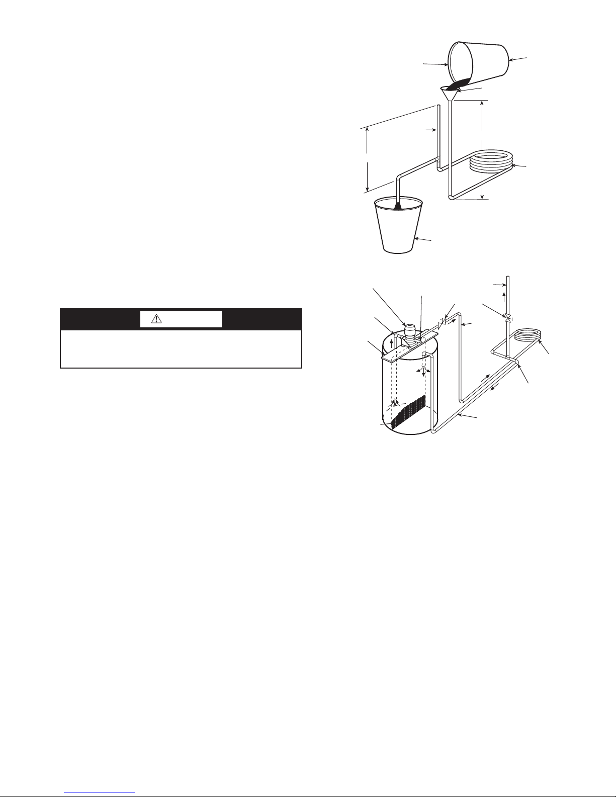
oil and cause eventual motor failure. Conduct annual dry oper-
Fig. 22 — Gravity Flow Method
FILL CONDENSER WITH
CLEANING SOLUTION. DO
NOT ADD SOLUTION
MORE RAPIDLY THAN
VENT CAN EXHAUST
GASES CAUSED BY
CHEMICAL ACTION.
PAIL
FUNNEL
CONDENSER
PAIL
3’ TO 4’
VENT
PIPE
5’ APPROX
1”
PIPE
SUCTION
PUMP
SUPPORT
TANK
FINE MESH
SCREEN
RETURN
GAS VENT
PUMP
PRIMING
CONN.
GLOBE
VALV ES
SUPPLY
1” PIPE
CONDENSER
REMOVE WATER
REGULATING VALVE
ation check and amperage check to ensure amp draw is no
more than 10% greater than indicated on serial plate data.
Condensate Drain Cleaning — Clean the drain line
and unit drain pan at the start of each cooling season. Check
flow by pouring water into drain. Be sure trap is filled to maintain an air seal.
Air Coil Cleaning — Remove dirt and debris from evap-
orator coil as required by condition of the coil. Clean coil with
a stiff brush, vacuum cleaner, or compressed air. Use a fin
comb of the correct tooth spacing when straightening mashed
or bent coil fins.
Condenser Cleaning — Water-cooled condensers may
require cleaning of scale (water deposits) due to improperly
maintained closed-loop water systems. Sludge build-up may
need to be cleaned in an open water tower system due to
induced contaminants.
Local water conditions may cause excessive fouling or
pitting of tubes. Condenser tubes should therefore be cleaned at
least once a year, or more often if the water is contaminated.
Proper water treatment can minimize tube fouling and
pitting. If such conditions are anticipated, water treatment
analysis is recommended. Refer to the Carrier System Design
Manual, Part 5, for general water conditioning information.
CAUTION
Follow all safety codes. Wear safety glasses and rubber
gloves when using inhibited hydrochloric acid solution.
Observe and follow acid manufacturer’s instructions.
Clean condensers with an inhibited hydrochloric acid solution. The acid can stain hands and clothing, damage concrete,
and, without inhibitor, damage steel. Cover surroundings to
guard against splashing. Vapors from vent pipe are not harmful,
but take care to prevent liquid from being carried over by the
gases.
Warm solution acts faster, but cold solution is just as effective if applied for a longer period.
GRAVITY FLOW METHOD — Do not add solution faster
than vent can exhaust the generated gases.
When condenser is full, allow solution to remain overnight,
then drain condenser and flush with clean water. Follow acid
manufacturer’s instructions. See Fig. 22.
FORCED CIRCULATION METHOD — Fully open vent
pipe when filling condenser. The vent may be closed when
condenser is full and pump is operating. See Fig. 23.
Regulate flow to condenser with a supply line valve. If
pump is a nonoverloading type, the valve may be fully closed
while pump is running.
For average scale deposit, allow solution to remain in condenser overnight. For heavy scale deposit, allow 24 hours.
Drain condenser and flush with clean water. Follow acid manufacturer’s instructions.
Fig. 23 — Forced Circulation Method
Checking System Charge — Units are shipped with
full operating charge. If recharging is necessary:
1. Insert thermometer bulb in insulating rubber sleeve on
liquid line near filter drier. Use a digital thermometer for
all temperature measurements. DO NOT use a mercury
or dial-type thermometer.
2. Connect pressure gage to discharge line near compressor.
3. After unit conditions have stabilized, read head pressure
on discharge line gage.
NOTE: Operate unit a minimum of 15 minutes before
checking charge.
4. From standard field-supplied Pressure-Temperature chart
for R-410A refrigerant, find equivalent saturated condensing temperature.
5. Read liquid line temperature on thermometer; then
subtract from saturated condensing temperature. The difference equals subcooling temperature.
6. Compare the subcooling temperature with the normal
temperature. If the measured liquid line temperature does
not agree with the required liquid line temperature, ADD
refrigerant to raise the temperature or REMOVE refrigerant (using standard practices) to lower the temperature
(allow a tolerance of ± 3° F).
29
Page 30
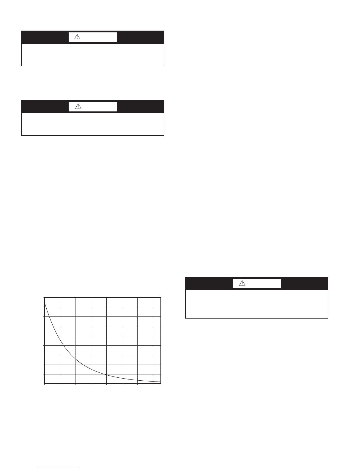
Refrigerant Charging
0.0
10.0
20.0
30.0
40.0
50.0
60.0
70.0
80.0
90.0
0.0 20.0 40.0 60.0 80.0 100.0 120.0 140.0
Temperature (degF)
Resistance (kOhm)
WARNING
To prevent personal injury, wear safety glasses and gloves
when handling refrigerant. Do not overcharge system —
this can cause compressor flooding.
NOTE: Do not vent or depressurize unit refrigerant to atmosphere. Remove and recover refrigerant following accepted
practices.
Air Coil Fan Motor Removal
CAUTION
Before attempting to remove fan motors or motor mounts,
place a piece of plywood over evaporator coils to prevent
coil damage.
Disconnect motor power wires from motor terminals before
motor is removed from unit.
1. Shut off unit main power supply.
2. Loosen bolts on mounting bracket so that fan belt can be
removed.
3. Loosen and remove the 2 motor mounting bracket bolts
on left side of bracket.
Slide motor/bracket assembly to extreme right and lift out
through space between fan scroll and side frame. Rest motor on
a high platform such as a step ladder. Do not allow motor to
hang by its power wires.
TROUBLESHOOTING
When troubleshooting problems with a WSHP, consider the
following:
Thermistor — A thermistor may be required for single-
phase units where starting the unit is a problem due to low
voltage. See Fig. 24 for thermistor nominal resistance.
Control Sensors — The control system employs 2 nom-
inal 10,000 ohm thermistors (FP1 and FP2) that are used for
freeze protection. Be sure FP1 is located in the discharge fluid
and FP2 is located in the air discharge. See Fig. 25.
Thermostatic Expansion Valves — Thermostat-
ic expansion valves (TXV) are used as a means of metering the
refrigerant through the evaporator to achieve a preset superheat
at the TXV sensing bulb. Correct superheat of the refrigerant is
important for the most efficient operation of the unit and for the
life of the compressor.
Packaged heat pumps typically use one bi-flow TXV to meter refrigerant in both modes of operation. When diagnosing
possible TXV problems it may be helpful to reverse the refrigerant flow to assist with the diagnosis.
Geothermal and water source heat pumps are designed to
operate through a wide range of entering-water temperatures
that will have a direct effect on the unit refrigerant operating pressures. Therefore, diagnosing TXV problems can be
difficult.
TXV FAILURE — The most common failure mode of a TXV
is when the valve fails while closed. Typically, a TXV uses
spring pressure to close the valve and an opposing pressure,
usually from a diaphragm, to open the valve. The amount of
pressure exerted by the diaphragm will vary, depending on the
pressure inside of the sensing bulb. As the temperature of and
pressure within the bulb decreases, the valve will modulate
closed and restrict the refrigerant flow through the valve. The
result is less refrigerant in the evaporator and an increase in the
superheat. As the temperature at the bulb increases the diaphragm pressure will increase, which opens the valve and
allows more refrigerant flow and a reduction in the superheat.
If the sensing bulb, connecting capillary, or diaphragm
assembly are damaged, pressure is lost and the spring will force
the valve to a closed position. Often, the TXV will not close
completely so some refrigerant flow will remain, even if inadequate flow for the heat pump to operate.
The TXV sensing bulb must be properly located, secured,
and insulated as it will attempt to control the temperature of the
line to which it is connected. The sensing bulb must be located
on a dedicated suction line close to the compressor. On a packaged heat pump, the bulb may be located almost any place on
the tube running from the compressor suction inlet to the
reversing valve. If the bulb is located on a horizontal section, it
should be placed in the 10:00 or 2:00 position for optimal
performance.
CAUTION
Use caution when tightening the strap. The strap must be
tight enough to hold the bulb securely but caution must be
taken not to over-tighten the strap, which could dent, bend,
collapse or otherwise damage the bulb.
Fig. 24 — Thermistor Nominal Resistance
The bulb must be secured to the pipe using a copper strap.
The use of heat transfer paste between the bulb and the pipe
will also help ensure optimum performance.
The bulb must also be properly insulated to eliminate any
influence on valve operation by the surrounding conditions.
Cork tape is the recommended insulation as it can be molded
tight to the bulb to prevent air infiltration.
30
Page 31
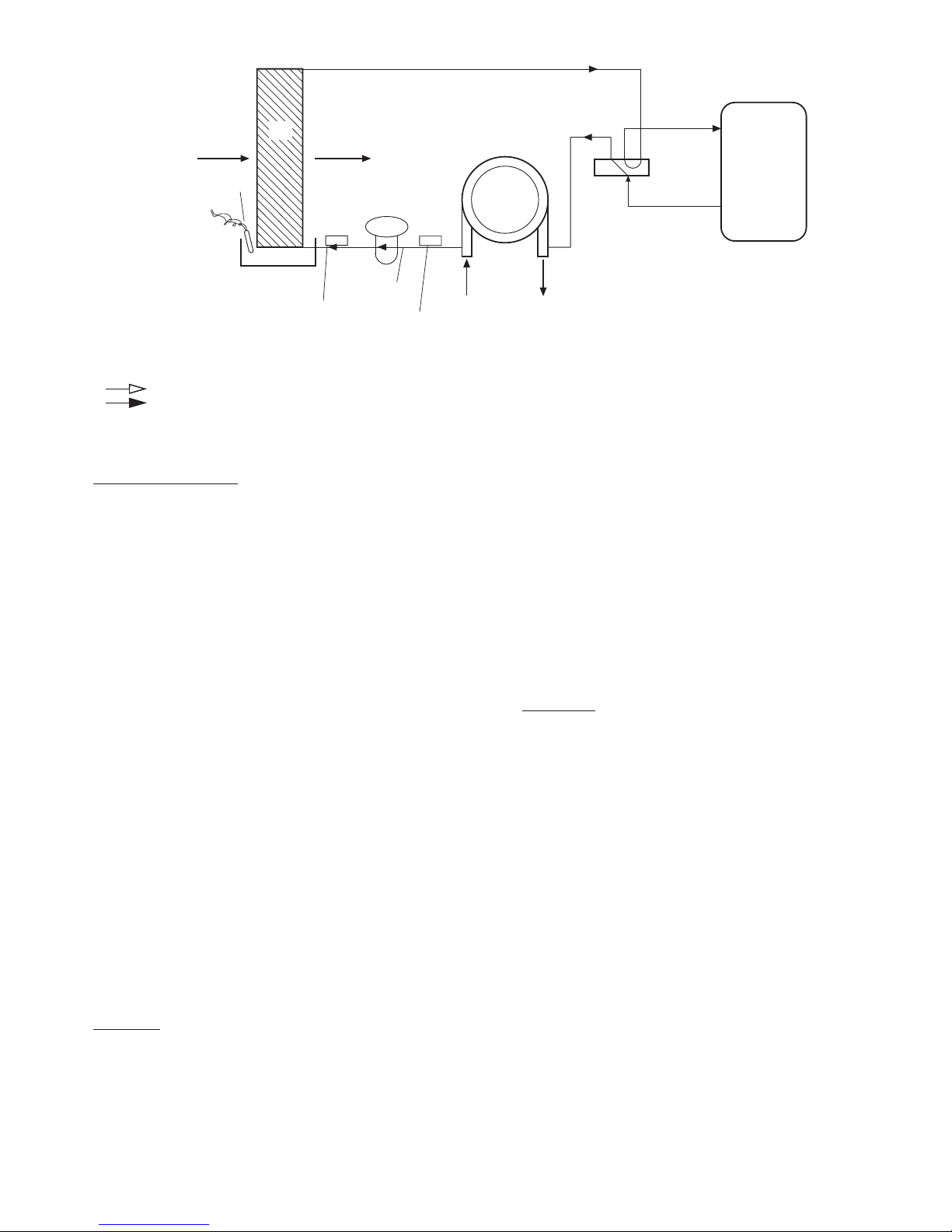
Causes of TXV Failure
SUCTION
COMPRESSOR
DISCHARGE
COAX
EXPANSION
VALV E
FP2
FP1
LIQUID
LINE
WATER IN
WATER OUT
CONDENSATE
OVERFLOW
(CO)
AIR COIL
FREEZE
PROTECTION
WATER
COIL
PROTECTION
THERMISTOR
(°F)
(°F)
AIR
COIL
AIRFLOW
AIRFLOW
LEGEND
Fig. 25 — FP1 and FP2 Thermistor Location
COAX — Coaxial Heat Exchanger
Airflow
Refrigerant Liquid Line Flow
— The most common causes of TXV
failure are:
1. A cracked, broken, or damaged sensing bulb or capillary
can be caused by excessive vibration of the capillary during shipping or unit operation.
If the sensing bulb is damaged or if the capillary is
cracked or broken, the valve will be considered failed and
must be replaced. Replacement of the TXV “power head”
or sensing bulb, capillary, diaphragm assembly is possible on some TXVs. The power head assembly screws
onto most valves, but not all are intended to be replaceable. If the assembly is not replaceable, replace the entire
valve.
2. Particulate debris within the system can be caused by several sources including contaminated components, tubing,
and service tools, or improper techniques used during
brazing operations and component replacement.
Problems associated with particulate debris can be compounded by refrigerant systems that use POE (polyol ester oil). POE oil has solvent-like properties that will clean
the interior surfaces of tubing and components. Particulates can be released from interior surfaces and may migrate to the TXV strainer, which can lead to plugging of
the strainer.
3. Corrosive debris within the system may happen after a
failure, such as a compressor burn out, if system was not
properly cleaned.
4. Noncondensables may be present in the system. Noncondensables includes any substance other than the
refrigerant or oil such as air, nitrogen, or water. Contamination can be the result of improper service techniques,
use of contaminated components, and/or improper evacuation of the system.
Symptoms
and will include one or more of the following:
• Low refrigerant suction pressure
• High refrigerant superheat
• High refrigerant subcooling
• TXV and/or low pressure tubing frosting
• Equalizer line condensing and at a lower temperature
than the suction line or the equalizer line frosting
• FP1 faults in the heating mode in combination with any
of the symptoms listed above
— The symptoms of a failed TXV can be varied
• FP2 faults in the cooling mode in combination with any
of the symptoms listed above. Some symptoms can
mimic a failed TXV but may actually be caused be
another problem.
Before conducting an analysis for a failed TXV the follow-
ing must be verified:
• Confirm that there is proper water flow and water temperature in the heating mode.
• Confirm that there is proper airflow and temperature in
the cooling mode.
• Ensure coaxial water coil is clean on the inside; this
applies to the heating mode and may require a scale
check.
• Refrigerant may be undercharged. To verify, subcooling
and superheat calculations may be required.
Diagnostics
— Several tests may be required to determine if
a TXV has failed. The following tools may be required for
testing:
1. Refrigerant gage manifold compatible with the refrigerant in the system.
2. Digital thermometer, preferably insulated, with wire leads
that can be connected directly to the tubing.
3. Refrigerant pressure-temperature chart for the refrigerant
used.
To determine that a TXV has failed, verify the following:
• The suction pressure is low and the valve is non-responsive. The TXV sensing bulb can be removed from the
suction line and warmed by holding the bulb in your
hand. This action should result in an increase in the suction pressure while the compressor is operating. The
sensing bulb can also be chilled by immersion in ice
water, which should result in a decrease in the suction
pressure while the compressor is operating. No change in
the suction pressure would indicate a nonresponsive
valve.
• Simultaneous LOW suction pressure, HIGH refrigerant
subcooling and HIGH superheat.
• LOW suction pressure, LOW subcooling and HIGH
superheat may indicate an undercharge of refrigerant.
HIGH subcooling and LOW superheat may indicate an
overcharge of refrigerant. The suction pressure will usually be normal or high if there is an overcharge of refrigerant.
31
Page 32
• LOW suction pressure and frosting of the valve and/or
equalizer line may indicate a failed valve. However,
these symptoms may also indicate an undercharge of
refrigerant. Calculate the subcooling and superheat to
verify a failed valve or refrigerant charge issue.
Repair
WARNING
Puron® refrigerant (R-410A) operates at higher pressure
than R-22, which is found in other WSHPs. Tools such as
manifold gages must be rated to withstand the higher pressures. Failure to use approved tools may result in a failure
of tools, which can lead to severe damage to the unit, injury
or death.
IMPORTANT: Due to the hygroscopic nature of the
POE oil in Puron refrigerant (R-410A) and other environmentally sound refrigerants, any component replacement must be conducted in a timely manner using
caution and proper service procedure for these types of
refrigerants. A complete installation instruction will be
included with each replacement TXV/filter drier assembly. It is of critical importance these instructions are
carefully understood and followed. Failure to follow
these instructions can result in a system that is contaminated with moisture to the extent that several filter drier
replacements may be required to properly dry the
system.
WARNING
Most TXVs are designed for a fixed superheat setting and
are therefore considered non-adjustable. Removal of the
bottom cap will not provide access for adjustment and can
lead to damage to the valve or equipment, unintended venting of refrigerant, personal injury, or possibly death.
CAUTION
Always recover the refrigerant from the system with suitable approved tools, recovery equipment, and practices
prior to attempting to remove or repair any TXV.
CAUTION
Use caution when tightening the strap. The strap must be
tight enough to hold the bulb securely but caution must be
taken not to over-tighten the strap, which could dent, bend,
collapse or otherwise damage the bulb.
CAUTION
Puron® refrigerant (R-410A) requires the use of synthetic
lubricant (POE oil). Do not use common tools on systems
that contain R-22 refrigerants or mineral oil. Contamination and failure of this equipment may result.
IMPORTANT: Repair of any sealed refrigerant system
requires training in the use of refrigeration tools and procedures. Repair should only be attempted by a qualified service technician. A universal refrigerant handling certificate
will be required. Local and/or state license or certificate
may also be required.
See Table 14 for suggestions of good practices regarding
regular repairs. See Table 15 for additional troubleshooting
information.
CAUTION
Disconnect power from unit before removing or replacing
connectors, or servicing motor. Wait 5 minutes after disconnecting power before opening motor.
Moisture Check — To perform moisture check:
• Check that connectors are orientated “down” (or as rec-
ommended by equipment manufacturer).
• Arrange harnesses with “drip loop” under motor.
• Check if condensate drain is plugged.
• Check for low airflow (too much latent capacity).
• Check for undercharged condition.
• Check and plug leaks in return ducts, cabinet.
DO DO NOT
Check motor, controls wiring, and connections thoroughly before replacing motor.
Orient connectors down so water cannot get in. Install “drip loops.” Locate connectors above 7 and 4 o’clock positions.
Use authorized motor and control model numbers for replacement. Replace one motor or control model number with another (unless
Keep static pressure to a minimum by:
• Using high efficiency, low-static filters.
• Keeping filters clean.
• Designing ductwork for minimum static and maximum comfort.
• Improving ductwork when replacement is necessary.
Size equipment wisely. Oversize system then compensate with low airflow.
Check orientation before inserting motor connectors. Plug in power connector backwards.
Table 14 — Good Practices
Automatically assume the motor is bad.
replacement is authorized).
Use high pressure drop filters.
Use restricted returns.
Force plugs.
32
Page 33
Table 15 — Troubleshooting
FAULT POSSIBLE CAUSE SOLUTION
Entire unit does not run Power Supply Off Apply power, close disconnect.
Blown Fuse Replace fuse or reset circuit breaker. Check for correct fuses.
Voltage Supply Low If voltage is below minimum voltage specified on unit data plate, contact local power com-
Thermostat Set the fan to ON, the fan should run. Set thermostat to COOL and lowest temperature set-
Blower operates but compressor
does not
Unit off on high pressure control Discharge pressure too high In “COOLING” mode: Lack of or inadequate water flow. Entering water temperature is too
Unit off on low pressure control Suction pressure too low In “COOLING” mode: Lack of or inadequate airflow. Entering air temperature is too cold.
Unit short cycles Unit oversized Recalculate heating and or cooling loads.
Insufficient cooling or heating Unit undersized Recalculate heating and or cooling loads. If excessive, possibly adding insulation and shad-
Thermostat Check setting, calibration, and wiring.
Wiring Check for loose or broken wires at compressor, capacitor, or contactor.
Safety Controls Check Complete C board red default LED for blink code.
Compressor overload open If the compressor is cool and the overload will not reset, replace compressor.
Compressor motor grounded Internal winding grounded to the compressor shell. Replace compressor.
Compressor windings open After compressor has cooled, check continuity of the compressor windings. If the windings
Refrigerant charge The unit is overcharged with refrigerant. Recover refrigerant, evacuate and recharge with fac-
High pressure Check for defective or improperly calibrated high pressure switch.
Refrigerant charge The unit is low on refrigerant. Check for refrigerant leak, repair, evacuate and recharge with
Low pressure switch Check for defective or improperly calibrated low pressure switch.
Thermostat Thermostat installed near a supply air grille; relocate thermostat. Readjust heat anticipator.
Wiring and controls Check for defective or improperly calibrated low pressure switch.
Loss of conditioned air by leakage Check for leaks in ductwork or introduction of ambient air through doors or windows.
Airflow Lack of adequate airflow or improper distribution of air. Replace dirty filter.
Refrigerant charge Low on refrigerant charge causing inefficient operation.
Compressor Check for defective compressor. If discharge is too low and suction pressure is too high, com-
Reversing Valve Defective reversing valve creating bypass of refrigerant from discharge of suction side of
Operating pressures Compare unit operation pressures to the pressure/temperature chart for the unit.
TXV Check TXV for possible restriction or defect. Replace if necessary.
Moisture, noncondensables The refrigerant system may be contaminated with moisture or noncondensables. Recover
pany.
ting, the unit should run in the cooling mode (reversing valve energized). Set unit to HEAT
and the highest temperature setting, the unit should run in the heating mode (reversing valve
deenergized).
If neither the blower or compressor run in all three cases, the thermostat could be miswired or
faulty. To ensure miswired or faulty thermostat verify that 24 volts is available at the low voltage terminal strip between “R” and “C”, “Y” and “C”, and “O” and “C”. If the blower does not
operate, verify 24 volts between terminals “G” and “C”. Replace the thermostat if defective.
are open, replace the compressor.
warm. Scaled or plugged condenser. In “HEATING” mode: Lack of or inadequate airflow.
Blower inoperative, clogged filter or restrictions in ductwork
tor recommended charge.
Blower inoperative, clogged filter or restrictions in ductwork
In “HEATING” mode: Lack of or inadequate water flow. Entering water temperature is too
cold. Scaled or plugged condenser.
factory recommended charge.
ing will rectify the problem.
pressor is not pumping properly. Replace compressor.
compressor. Replace reversing valve.
refrigerant, replace filter dryer, evacuate the refrigerant system, and recharge with factory
recommended charge.
33
Page 34

© Carrier Corporation 2014
Manufacturer reserves the right to discontinue, or change at any time, specifications or designs without notice and without incurring obligations.
Catalog No. 04-53500104-01 Printed in U.S.A. Form 50PT-5SI Pg 34 1218 6-14 Replaces: NEW
8733953040
Page 35

50PTH,PTV
START-UP CHECKLIST
CUSTOMER:___________________________ JOB NAME: _______________________________________
MODEL NO.:___________________________ SERIAL NO.: _____________ DATE: _________________
I. PRE-START-UP
DOES THE UNIT VOLTAGE CORRESPOND WITH THE SUPPLY VOLTAGE AVAILABLE? (Y/N)
HAVE THE POWER AND CONTROL WIRING CONNECTIONS BEEN MADE AND TERMINALS
TIGHT? (Y/N)
HAVE WATER CONNECTIONS BEEN MADE AND IS FLUID AVAILABLE AT HEAT EXCHANGER?
(Y/N)
HAS PUMP BEEN TURNED ON AND ARE ISOLATION VALVES OPEN? (Y/N)
HAS CONDENSATE CONNECTION BEEN MADE AND IS A TRAP INSTALLED? (Y/N)
IS AN AIR FILTER INSTALLED? (Y/N)
II. START-UP
IS FAN OPERATING WHEN COMPRESSOR OPERATES? (Y/N)
IF 3-PHASE SCROLL COMPRESSOR IS PRESENT, VERIFY PROPER ROTATION PER INSTRUCTIONS.
(Y/N)
UNIT VOLTAGE — COOLING OPERATION
PHASE AB VOLTS PHASE BC VOLTS PHASE CA VOLTS
(if 3 phase) (if 3 phase)
PHASE AB AMPS
PHASE BC AMPS PHASE CA AMPS
(if 3 phase) (if 3 phase)
CONTROL VOLTAGE
IS CONTROL VOLTAGE ABOVE 21.6 VOLTS? (Y/N) .
IF NOT, CHECK FOR PROPER TRANSFORMER CONNECTION.
TEMPERATURES
FILL IN THE ANALYSIS CHART ATTACHED.
COAXIAL HEAT
EXCHANGER
COOLING CYCLE:
FLUID IN
FFLUID OUT F PSI FLOW
HEATING CYCLE:
FLUID IN
FFLUID OUT F PSI FLOW
AIR COIL COOLING CYCLE:
AIR IN
HEATING CYCLE:
AIR IN
Manufacturer reserves the right to discontinue, or change at any time, specifications or designs without notice and without incurring obligations.
Catalog No. 04-53500104-01 Printed in U.S.A. Form 50PT-5SI Pg CL-1 6-14 Replaces: NEW
FAIR OUT F
FAIR OUT F
Page 36
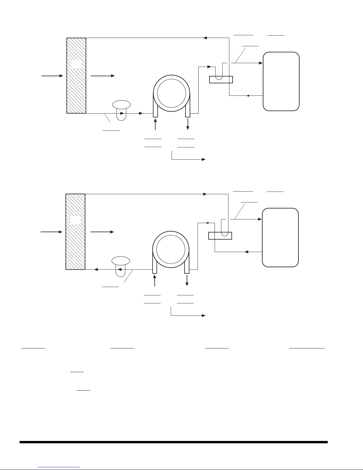
HEATING CYCLE ANALYSIS
SUCTION
COMPRESSOR
DISCHARGE
COAX
EXPANSION
VALVE
°F
°F
AIR
COIL
°F
PSI
FLUID OUT
FLUID IN
°F
PSI
°F
LIQUID LINE
PSI
°F
SAT
CONTACT CARRIER COMMERCIAL SERVICES
OR PRODUCT MANAGEMENT FOR ACCEPTABLE
PRESSURE DROP TO DETERMINE FLOW RATE
COOLING CYCLE ANALYSIS
AIR
COIL
°F
HEAT OF EXTRACTION (ABSORPTION) OR HEAT OF REJECTION =
FLOW RATE (GPM) x TEMP. DIFF. (DEG. F) x FLUID FACTOR* =
°F
EXPANSION
VALVE
LIQUID LINE
COAX
°F
FLUID IN
°F
PSI
FLUID OUT
°F
PSI
CONTACT CARRIER COMMERCIAL SERVICES
OR PRODUCT MANAGEMENT FOR ACCEPTABLE
PRESSURE DROP TO DETERMINE FLOW RATE
(Btu/hr)
PSI
°F
SUCTION
COMPRESSOR
DISCHARGE
SAT
CUT ALONG DOTTED LINE CUT ALONG DOTTED LINE
SUPERHEAT = SUCTION TEMPERATURE – SUCTION SATURATION TEMPERATURE
=
(DEG F)
SUBCOOLING = DISCHARGE SATURATION TEMPERATURE – LIQUID LINE TEMPERATURE
(DEG F)
=
*Use 500 for water, 485 for antifreeze.
© Carrier Corporation 2014
Manufacturer reserves the right to discontinue, or change at any time, specifications or designs without notice and without incurring obligations.
Catalog No. 04-53500104-01 Printed in U.S.A. Form 50PT-5SI Pg CL-2 1218 6-14 Replaces: NEW
8733953040
- - - - - - - - - - - - - - - - - - - - - - - - - - - - - - - - - - - - - - - - - - - - - - - - - - - - - - - - - - - - - - - - - - - - - - - - - - - - - - - - - - - - - - - - - - - - - - - - - - - - - - - - - - - - - - - - - - - - - - - - - - - - - - - - - - - - - - - - - - - - - - - - - - - - - - - - - - - - - - - - - - - - - - - - - - - - -- - - - - - - - - - - - - - - - - - - -
 Loading...