

Page 1
Carrier
Single-Package
y-
Heat Pumps
The number 1
f<x heating & cooling camrr^rcy,
iixJustrial oc eckicational bialdlngsin 5, and 9 ton caf^ities.
4.
I
¿^ ! '0
I V
Jiy
50RQ,PQ
Heating 62,000 to 112,000 Btuh
Cooling 59,000 to 107,000 Btuh
© Carder Ccrpof3t5on 7977
Form 50RQ-3P
Page 2
The heat pump reverse cycle controls the weather all year round
The Carrier single package heat pump — compact,
efficient, reliable. It puts the weather to work for you
and lowers operating costs.
Thermodynamically, there is no difference be
tween a heat pump and an air conditioning unit or
refrigerator. The heat pump moves heat from a colder
heat source to a warmer heat sink thru the vapor
compression cycle. (The same as a refrigerator or air
conditioner.)
The difference, from a practical standpoint, is in
the heat pump's ability to reverse the roles of the
evaporator and condenser coils.
The heat pump takes advantage of the fact that
even cold winter air contains heat that can be
absorbed for heating a building. During cooling
season operation, the unit can be set to reverse the
evaporator and condenser coils, absorbing heat from
inside the building and discharging it outside — like a
standard air conditioner.
The operating cost advantage of the heat pump
occurs primarily during the heating mode. Depending
on outdoor temperature, the heat pump can actually
produce two to three units of heating energy for
every unit of electrical energy it uses.
The heat pump's cost saving reverse cycle prin
ciple uses refrigerant circulated within a compact,
closed circuit coil to absorb and transfer heat from
one area to another.
The process begins with the evaporator (cooling)
coil absorbing heat from the air around it. The
compressor then pumps the refrigerant to the con
denser where this heat is then rejected to the
surrounding air.
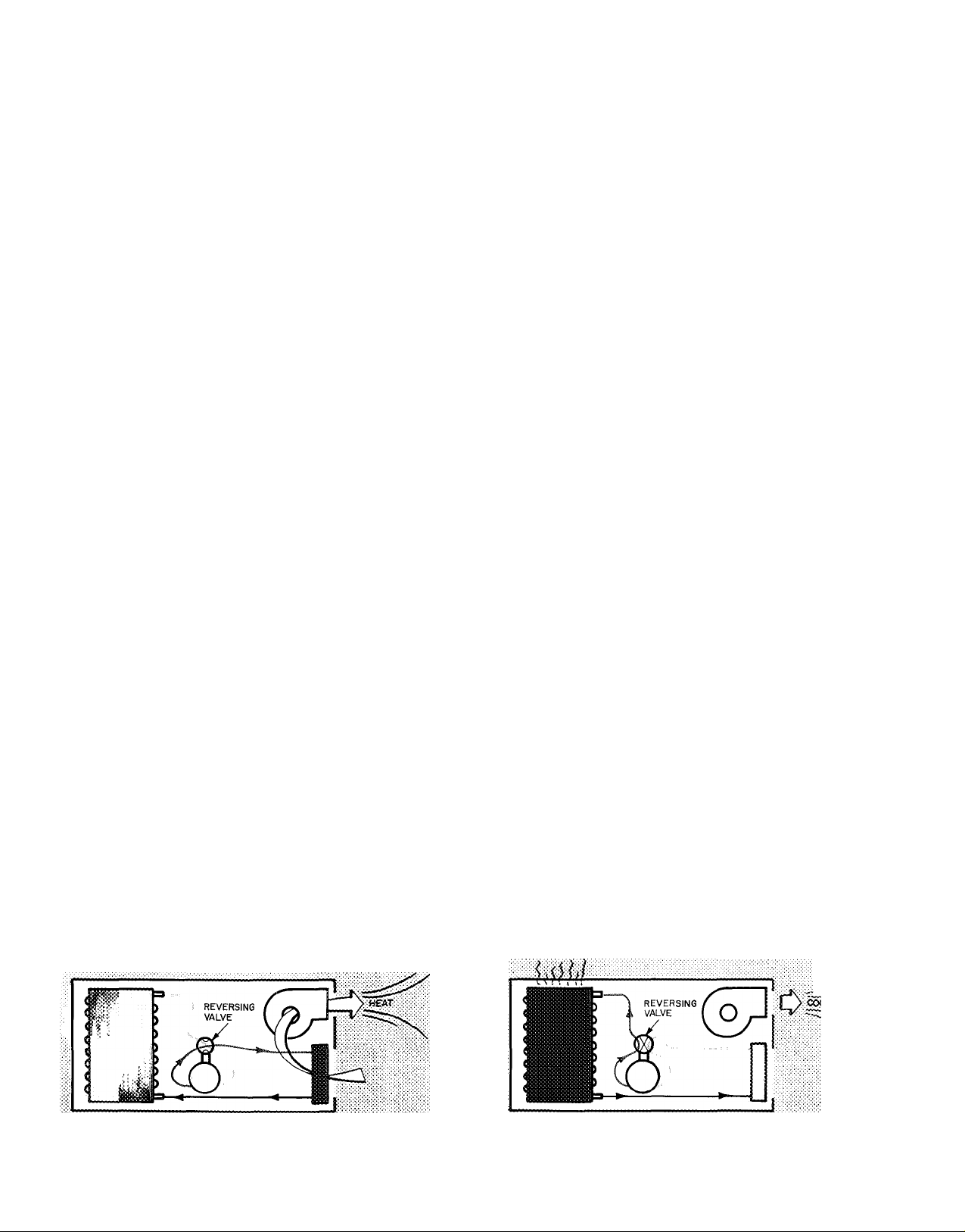
As shown in the diagram, the heat pump makes
double use of the two coils by means of a reversing
valve. The two coils alternate as evaporator or
condenser, depending on whether cooling or heating
is required.
Heating Cycle — Refrigerant enters ^ outdoor coil
(evaporator) at a lower temperature than the surrounding
outdoor air and heat is absorbed by refrigerant. The
refrigerant then passes thru tiie reversing valve and into the
compressor v^/here it is brouÿrt to a nigit temperature and
pressure. The hot refrigerant ieaves the compressor, fiows
thru the reversing valve to the indoor coil (condenser). Heat
is ihert rejected to the return air from the hot refrigerant as
the return air passes over the irxioorcoii (condenser).
Cooling Cycle — The two cotis exchange roles as evaporator
and coftdenser tftry tite action of the reversing valve.
Althougii reversed, system operation is exactly the same.
Refrigerant enters the evaporator (indoor coil) at a lower
temperature than the return air, heat is absorbed from
indoors, the cocker air is then distributed throughout the
building. Refrigerant ieaves the evaporator, flows thru the
reversing vaive and into tha compressor where it is brought
to a higher teinperature and pressure. The hot refrigerant
gas flows from the compressor^-ftiru the reversing valve and
into the outdoor coil (condenser). The outdoor coii (con
denser) rejects the heat from the hot refrigerant to the
cooler outdoor air as it passes over t)te coil The heat
transfer cycle is now ready to be repeated.
JL
Page 3
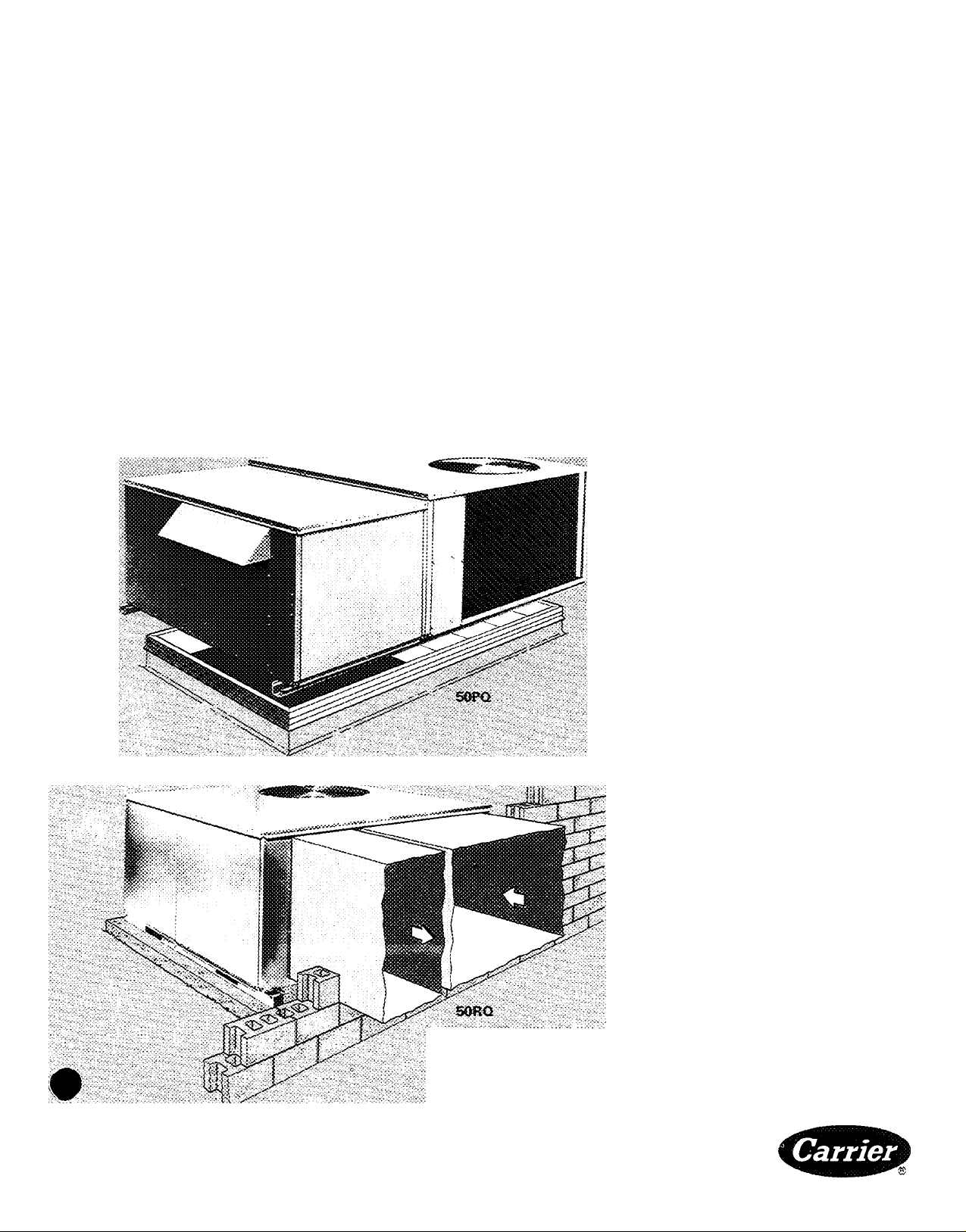
A great performer... with unmatched versatility
As the concern for energy grows
and grows, Carrier's 50RQ/PQ
single package heat pump looks
better and better. Short gas supply
and high cost electric power are no
problem with these versatile units
in operation. They're engineered
for a wide range of application . .
and installation is easy. For a
curbed heat pump with plenum, in
one piece ready to swing into place,
there's the 50PQ rooftop Or select
the RQ uncurbed ... on a slab for
horizontal air delivery. Or take the
RQ, attach the accessory plenum at
New and improved features for a lifetime of
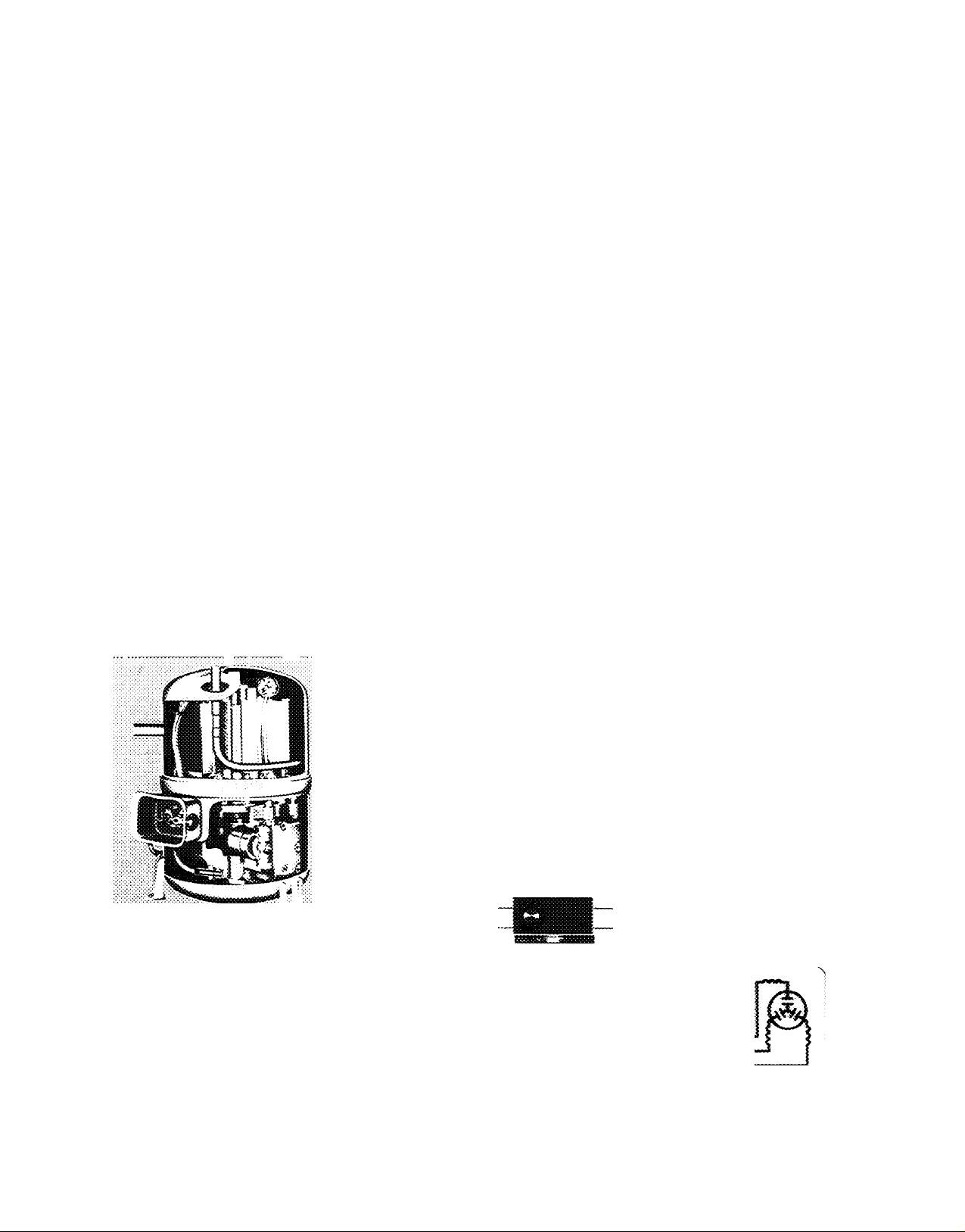
II New compressor for heavy duty
service — Carrier's new P compressor
more than meets the rigorous demands of
heat pump operation. Most efficient and
reliable hermetic in Carrier equipment
Thicker crankshaft Bigger bearing jour
nals. Larger valves. Extra large oil pump.
Crankcase heater.
the jobsite and it's a PQ
With an excellent cooling HER,
heating C.O P. among the highest in
industry, factory installed options
and field installed accessories, these
units will match specifications for
the most varied building
requirements
If you're looking for the reliable
one, the efficient one, the flexible
one . . the number 1 heat pump
on the market, LOOK TO
CARRIER!
dependable performance.
'I Signal-LOCTivi _ Carrier's new com
pressor protection system. Holds the
compressor off the line if any operational
or safety device trips the compressor
Operation of any one of the following
devices trips the compressor and lights an
indicator light on thermostat low-
pressure switch, high-pressure switch,
indoor coil freezeup thermostat, internal
line-break overload. Unit can be reset
manually at the thermostat Carrier
Exclusive.
11 Separate System capability (008,010
units) — Individual, independent refrig
eration systems. Operate circuit required
to maintain desired temperature. Provides
for stand-by operation. Less down time,
lowers service costs. Dual compressor
units with 2-stage heating and cooling —
operate with excellent part-load per
formance on heating and cooling. Elec
tric resistance heat is locked out above
40 F. This lowers demand charges and
costs Carrier Exclusive.
II Terminal strip — located in base unit
control box for easy connection to room
thermostat, outdoor thermostat(s),
emergency heat control, economizer and
electric heat
i> Exclusive, innovative variable circuit
refrigeration system — capacity and
COP are among the highest in industry
Maximizes refrigerant to air heat transfer
on both heating and cooling cycles No
other heat pump has it. Carrier Exclusive.
I' Automatic defrost system — Keeps
coil frost-free at temperatures below
40 F. Chrono-temp control activates de
frost system every 90 minutes if required
Automatically deactivates defrost cycle
when coil is clear or after a maximum of
10 minutes. Carrier Exclusive.
SSGNAL-LOC HEAT PUMP PROTECTOR
r—C
UNE8f5EAK
LI-I
L2-
L3-
Page 4
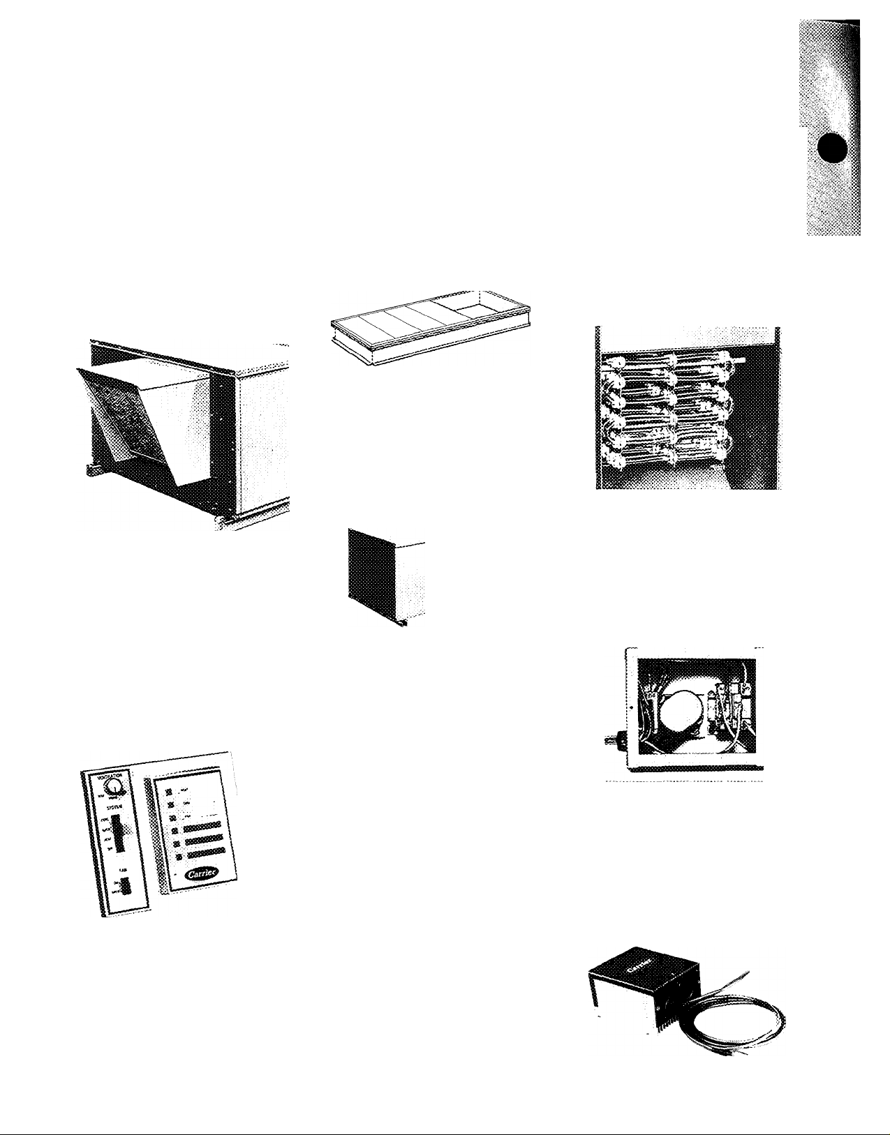
Accessories and factory installed options
Economizer assembly is available; as s;
factory-installed option or field-installed;
accessory. Located in plenum, it provides;
low-cost cooling on in-between days,’
Automatically controlled dampers open;
to admit cool, filtered outdoor air The:
compressor(s) and outdoor air fan remain;
off to save energy if the outdoor tern-'
perature is low enough to satisfy cooling;
requirements without compressor;
operation. ^
I Remote control panel consists of a sep
"marate heating and cooling thermostat'
assembly plus a decorative wall-mounted '
■i-. rj panel In addition to switches for heating,*
:S|cooling and fan operation, the panel
‘i-^^.icontams 6 indicator lights and, for -
■ 4,1 economizer-equipped units, a ventilation.
] control knob.
Roof Curb with insulated base pans
supports PQ unit (RQ unit with accessory
plenum) and frames roof opening for
plenum and interior ductwork. Once curb
is in place, and ductwork connected, unit
can be placed anytime ~ to meet your
schedule. Curb design meets all National
Roofing Contractors Association (NRCA)
requirements.
Downturn plenum is standard equipmervL, ■
factory-installed on PQ units, field-;
installed accessory on RQ units. Directs ^
airflow downward and provides weather-;
proof openings for ductwork connec
tions. Unit with plenum is curb mounted.;
Thennostat and suUiase (24 V} Acces
sory package provides for selection of
heating, cooling, continuous or automatic
fan cçieratîoR. Works hand-in-fiand with
Signal-LOC circuit. Subbase has v^ming îîÿit (LK-OUT) to automaticaSiy in
dicate compressor lockout condition.
Occupant îs immedîaitely avrare if com
pressor is inoperative Sue to malfunction.
Emergency beat control — Accessory
emergency heat subbase and relay aliow
occupant to manually switch compressor
off and electric heat on if warning light
indicates system rnaifunction. Can be
used for quick morning warm-up or to
merely lock out compressor.
Electric resistance heaters — Available as
factory-installed option or for field in
stallation Complete with high temper
ature limit switches and overcurrent pro
tection. Qffered in 4 heating capacities
for each unit. Where heaters are factory
I installed, unit electrical input is single-
;j point at a factory-supplied terminal
J block. Connection point is suitable for
I copper or aluminum wire (except for
i200-v, 3-phase unit with 1.5 1 electric
:1 heat ratio which uses copper only).
Time Guard® circuit protects compressore
against thermostat "jiggling," automati-f
cally prevents compressor from restarting-;:
for at least 5 minutes after a shutdown.
Accessory prevents short cycling of com-:-;
pressor if thermostat is rapidly changec;
(field installed)
i Motormaster® Head Pressure Control —
i Units are designed to operate at outdoor ,
i temperatures down to 35 F on cooling;
I mode Below 35 F, accessory 32LT ;
I Motormaster control modulates outdoor;
! fan motor to maintain correct condensing >
1 temperature at outdoor temperatures;
down to -20 F.
^Alternate motor ;tnt( drive, a factory-
installed cation, provides extra perform
ance for instaiiaiioos requiring hi^sr
hors^jower die standard motor has
to offer.
Outdoor tfoemtostat($) — Used to lock
out electric heat above certain outdoor
temperature for economical operation.
Fietd-instaiied with wide range of adjust
ments availabie to suit building design
requirements.
Page 5
hysical data
UNIT 50RQ,PQ
OPERATING WEIGHT (lb)
Unit 50RQ (no plenum)
Unit 50PQ (plenum)
With Economizer
Roof Curb
006
460
590
620
175
008 010
765
925
955
225
825
1005
1035
225
No. ...Type 1 ,6P
Capacity Steps (%)
0, 100
REFRIGERANT R-22
Charge (lbs) Sys 1, Sys 2
OUTDOOR COIL
Total Face Area (sq ft)
OUTDOOR AIR FAN
Nominal Cfm
No. ...Diam (in.)
Motor Hp...Kw
INDOOR COIL
Total Face Area (sq ft)
9 2, -
2-Row, Copper Tube, 15 Aluminum Plate Fins/in
11.7
ropeller Type, Direct Drive
4000
1. 22 1 .26
Уг ..0.8
4 0
P
Copper Tube, 15 Aluminum Plate
Rows 4
INDOOR AIR FAN
One, Centrifugal Adjustable Belt Drive
Size (in.) 10x9
Nominal Cfm 2000
Rpm Range
Std 920-1300 690- 980
Alt
1070-1460
Max Allowable Rpm 1600
Fan Pulley Pitch Diam (in.)
Center Line Distance (in.)
Motor Hp (See note)
Max Bhp
INDOOR AIR FILTERS (50DP) TYPE
No. ...Size (in.)*
*Paciory inS'alled in plenum Dnii: 50RQ,PQ008 will accept 2-in thick filters, field supplied
NOTE: Nominal rpm for 50RQ,PQ006,008 is 3450; for 50RQ.PQ010 Is 1725
Std 9 0
Alt
9 0
15V4
Std
Alt
Std
Alt
1 18
1.69
2 20x25x1
%
1
1 0% efficient, Disposable Fibe
2...6P
0, 50, 100
R-22
6 4, 7 0
17.0
7000
1.1
6 56
12x11
3000
805-1093 800-1090
1500
12
12
1678
1
IV2
1 69
2.11
2 20x25x1
2...16x25x1
Fins/in.
.1--. .1. 4
____________
" Glass
2. P
0, 60, 100
R-22
10 5, 8 0
22 5
7000
1. 26
1.. 1.35
8 5
12x11
3600
690- 980
1500
6
6
1678
iVa
2
2 5
TJ
2 20x25x2
2 16x25x2
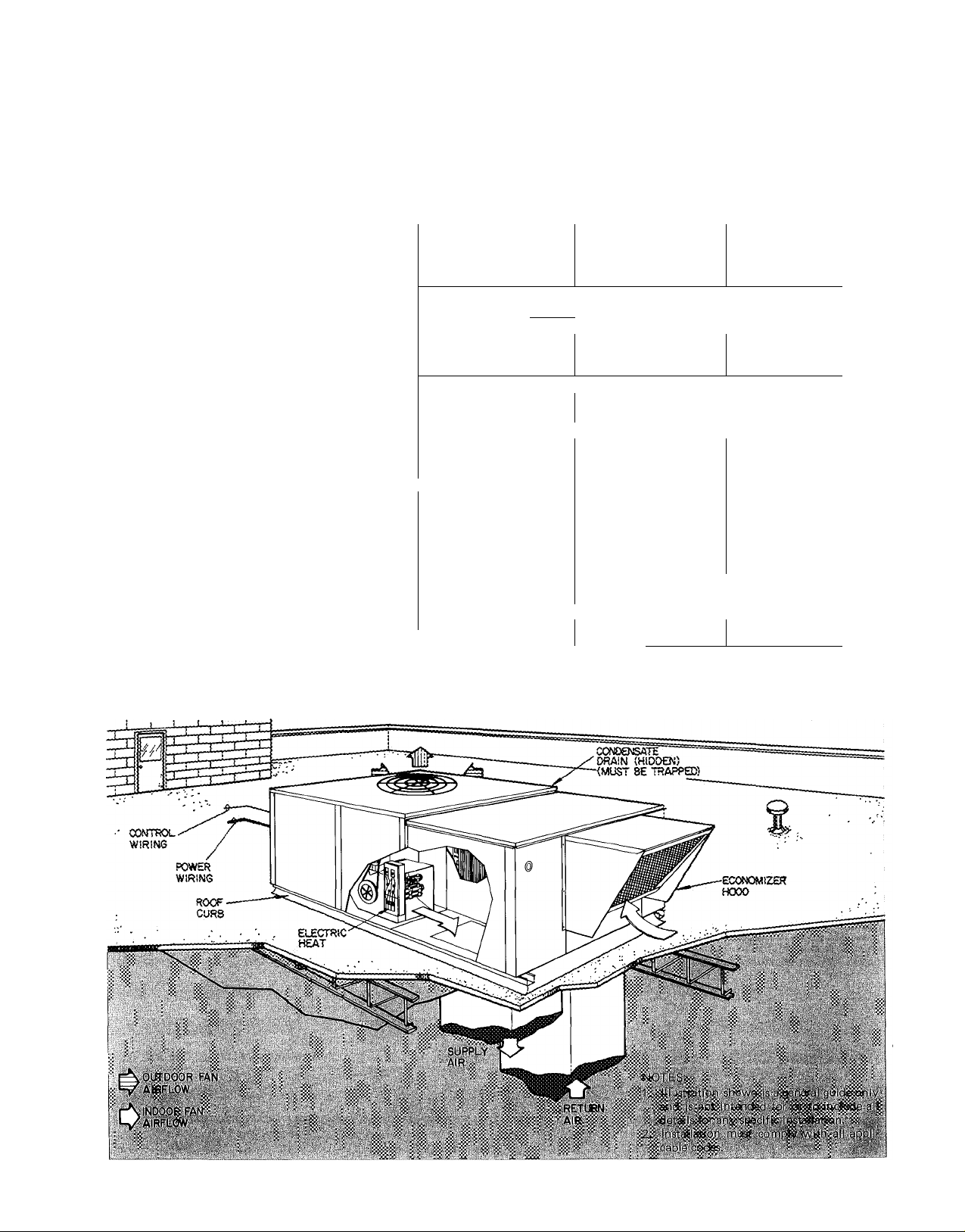
Typical piping and wiring
Page 6

Base unit dimensions
l| 0!AM KO
ACCESSORY
ELECTRIC HEATl
electrk: heat h
(OFTiONAL) CmTG'
i^ Ar t A
^ BOLT a NUT,.
FACTORY SUPPLIED
^ OUTDOOR COIL Alf?FLOW
C[)!NElOOR COiL AJfS^OW
i ¡SPACE REQUtREO FOR SERVICE
CLEARWCE AND AIRFLOW
U-V,, * :
^ D:AM
HOLE
DJM E NS S ON S { f t- i n. )
UH5 T ;
A
50R Q 00 6 I 3- g y.
50R Q 00 8 :
SO RQ O 10 i
5-
5- 0 *^ 4
SO PC t Q0 6 !
saP Q oo a •
50P Q & J0 : ;
7-> 0
8- 3 ii .
B
4-j y ,
i
1 4 - 8* ? i6
j 4- S '^ «; ,3 -2 - yt 6 i 2- 3 3
5-2%.
3-7 - y, 4
5-2%
5-2%
4-8 * y, 4
1 4 - 8^ 4
¡Die
3- 7 ^4i- 0? , i 2 - 0
}- 2- K s i 2 -3 5
; 3-3i 3-
: 3- 5‘ K .4 i 2 - 3 ^4
3-5 ^ 4 i 2 - 3 ^ 4
0-2 ^ 4
0-2 ^ 4
0-2X4
6%
0-3 3 4
0-3X4
0-3X4
Ce rt i if e ci cS f T> e «s i or i d r aw i ng s a r ea v ai t eb f eo f i r eq - ue s f.
C
1
” ^
I 1
2-0X4
x>2 - 3X < ^ '
Z2-9%:<
5-3
i 5- 3 1
! 6 - ; X 4 !
i 7- i i' X 4
i 0- 5X4 12-5V
■-
3-8X4
2-3 X
4
ROOF
OPERINSS
K
2-6 X
2-6 %
3-2 %
2-5X4
3-4
■ ■
%
2-5 % 43-4%
3-1X4
2-0
Page 7

Accessory dimensions
PLENUM (5OR0)
8AS£ i«!T
CA8!N£T
OUTLINE
BASE UN5T 50R0006
A
ROOF CURB DiMENSlONS
(ft-in.)*
A
B
C
0
E i-
F
G
4%
f 5 -
2-
i 7- 07 i a :
i: y.
6Va
i
4-G V s
2-3%^
■0- i 0- 1
i 1- 5^ ^ *:
1-
7%
i 2- O^ a
4%
■—i
-
L±£ l __ .
7-0 i (i
4-0 %
2-3 y :s
0-T . %a
2-0 ^ 6
2-0
B
C
D
E
F
G
*C ur b d im e ni o ns al s o a pp l y t o 5 0R Q u n it s w i th
fi et d -i n st a üe c i a cc e ss o ry pl e nu m .
PLENUM DiMENSlONS
(ft-in.)
50RCM)0850RQ010
2-
3‘
2-
9%a
4-
1-
ri
u-
1-
2-
V1
1%
6Va
T%:
1 ^ 6
5Xa
2%
5-
2-
3^X 6
0-
1%6
1-
5.*7i6
2-
11% «
1-
2S% OüTSiOE
a:b pamper
ANO HOOD
3-2 % e
5-2 %
2-3 % a
0- 1% a
1- 5^% a
3-1 % a
2- 7% a
BASE UNiT CORNER WEIGHTS <!b) FOR
ROOF fNSTALLATlON
50RQ
50PQ
A
UNÎT
006 i V34 ; 84 j ¡21
008 i 157 1 142 222 244
0)0 i 169 i 153 I 239 ^64
006 I 550 ; 108 i 126
B
150
576
356
ECONOMiZER HOOD DfMENSiONS
(ft-in.)
WWT
i 50RQ,P0006 Î 50R<J,FQ008 i SORQ,P<S010
A
B
1
......
1-3%«
! 1-7%« Î
.....
2-5% i 2-7%
1-7%« 1 2-3%
Page 8

Selection procedure (with example)
I Determine job requirements. IV Adjustments to capacities and Kw's for additional indoor fan
Estimated requirements motor heat for statics above 0.2 in. wg at listed cfm's.
Cooling load - total capacity
Outside air temperature (Cooling).....................................95 F operate at 2,000 cfm with 0.66 ESP to overcome the
- sensible capacity........................... 42,000 Btuh '"■ ^9 n"
Air entering indoor coil (Cooling) wb
Air quantity (cfm)........................................................2,000 1,208 rpm, 1,130 watts.
External static pressure - ESP (in. wg)
Heating load........................................................... 60,000 Btuh fable at required ESP.
Outdoor temperature (winter design)
Air entering indoor coil (Heating).......................................70 F 2,000 cfm *.2 83
Power supply
..............................................................
_ . . . (Diff in Kw) = 0 30
etermine unit size. ^ *NOTE Use motor Kw from RQ fan tables for .2 in ESP at
Select unit on cooling capacity. specified cfm for all plenum applications.
Enter the cooling capacity table at the given air quantity Adjust all capacities for additional IFM heat at higher
and evaporator entering wet bulb (2,000 cfm, 64 ewb). statics than .2 in. wg.
Read across table for net total capacity (TC) and net Diff (Btuh) = 3 413Btu/Kw x Kw
sensible capacity (SHC), under the condenser entering air ^ 3 413 x 30 = 1 024 Btuh
temperature (95 F) to find by interpolation TC of 56,000 rnni INC
and SHC of 47,400 at 2,000 cfm, 64 F wb for the , ,
RORonnK Adjusted TC = TC — Diff (Btuh)
Since these net capacities have been calculated at 0.2 in. wg Adjusted SHC = SHC — Diff (Btuh)
external static (ARI condition), for any additional static — ^ 4qq _ ^ Q24 = 4g 375
the net capacities must be adjusted to reflect the resulting Adjusted power input = Kw* + Diff '
IFM heat. To obtain the total required static,all accessory ^ 7 g + g 30 8 1 Kw
pressure drops must be calculated. Therefore, calculation *Kw-unit total from 'cooling capacity table at selected
of heater requirements must be made since pressure drop conditions
varies for each size of electric heater. HEATING
III Heating requirements — number of electric heaters required. Adjusted heating capacity = 18,000 -1- 1,024 = 19,024
Enter instantaneous/integrated heating ratings at 006 size Adjusted power input = Kw** -t Diff (Kw)
and 2,000 cfm. Under temperature at air entering outdoor =42-t 30 = 45 Kw
coil, -10 F, the Integrated heating capacity is 18,000 Btuh. **Kw from heating capacity tables of selected conditions.
The heating load is 60,000 Btuh, therefore, 42,000 Btuh V Corrections to SHC for dry bulb above or below 80 F - see
additional electric heat is necessary. Enter electric resist- SHC correction factor table. For this example, no correction
ance heater capacity table at 006 size and 230-3-60. The is necessary since the entering dry bulb is 80 F.
.754 heat ratio/or 13 Kw electric heater most closely Therefore, the final net capacities are
satisfies the electric heater requirement. SHC = 46,376 Btuh
13Kwor — 44,400 Btuh (from Electric TC = 54,976 Btuh
44,400 -t- 18,000 — 62,400 Btuh sensible capacity for the job application.
...................................
................................
54,000 Btuh The .754 electric heater resistance at 2,000 cfm is 0 26
64 F heater pressure drop.
gQ p From the fan tables at 2,000 cfm with 0.66 ESP requires
.................................
.............................
0.4 NOTE For PQ units or RQ units with plenums, use PQ fan
—10 F ESP IFM Kvy
230-3-60 .66 1.13
, , , , = 56,000-1,024 = 54,976 Btuh
Heating Capacities Table) The 50RQ at the required design conditions has enough
Performance data
COOLING
UNIT
CFM Cap. .
(Btuh)
50RQ
2000 59,000 7.5 62,000 2.8 35,000 2.0
006
50RQ
3000
008
SORQ
010
SOPQ
006
SOPQ
008
50PQ
010
88,000 7.8 91,000
3Ó00
108,000
2000 59,000
3000 87,000 7 6 92,000 2.8 52,000 2 0
3600
1 07,000 7 5 113,000 2.8 62,000 2 0
HTG (Hi -Temp)
EER
Cap.
(Btuh)
7.7
11 2,000 2.8 61,000 2 0
7.4 62,000
C.O.P.
2.8 51,000 2.0
2.8 35,000 1.9
(Btuh)
HTG(L
Cap.
ARI CAPACITY RATINGS
o-T emp)
C.O.P.
Rated in accordance with
ARI Standard 240-75.
Ratings are net values, reflecting the effects of circulating fan heat
Supplementary electric heat is not included, Ratings are based on:
Cooling Standard: 80 F db, 67 F wb indoor entering air temperature
and 95 F db air entering outdoor unit
Hi-Temp Heating Standard: 70 F db indoor entering air temperature
and 47 F db, 43 F wb air entering outdoor unit
Lo-Temp Heating Standard: 70 F db indoor entering air temperature
and 17 F db, 1 5 F wb air entering outdoor unit
Page 9

NET COOLING CAPACITIES"
UNIT
EVAP AIR CONDENSER ENTERING AIR TEMPERATURE (F)
Cfm
50RQ
006
008
010
Ewb
BF
72
1800
67
056
62
72
2000
67
063
62
72
2500
67 62 46
081
62 58 55 8 3
72
2700
67 92
048
62
72
3000
67
055
62
72
3700
67
070
62 90 85 11 3
72
3200
67
043
62
72
3600
67
050
62
72
4500
67 115 92
064
62
BF — Bypass Factor
Ewb _ Entering Wet Bulb
TC85SHC К w TC95SHC
66 32 7 7 64 3’
6'
42 7 4
56 51 7 1 52
66
32 7 9
62 43 7 6 59
57 53
33
66
100
48 11 0
64
84
77
101 50 11 1 97 49 11 8 94 48 12 0 92 47 12 4 85 45 12 9
94 67
86
81 10 4 81 78 10 9
101
51 11 8 98 51 12 6
95 71
123 63 13 8 117
113 80 13 2 107 78 13 8 103 77 14 1 99
103 97 12 7
124 65 14 0 119 63 4 7 115 62 15 0 112 62 15 4 104 58 15 9
115 85 13 5
106
102 13 0 99 98 13 6
124
67 15 2 118
108 107
58 41 7 7
64
54 51 7.7
7 3
64 32 9 1 62 32 9 3
8 6
59 46 8 8 57 45 8 9
8 4
56
96
10 7 87
10 3 79
88 65 11 3
10 8
90
11 5
86
97
108 83 14 1 105 81
14 8 108 90 15 4 105
14.3 102 102 15.0 99 99
Kw
8 0
7 4 51
5C
31 8 3
42 7 9 57 42 8 1
52 8 6
47
11 6
6'
11 2
74
10 8 76 73
12 1 87 69 12 4
7C
81 11 9
ÓÌ
14 5
13.3 94 91
93
Ó6 16 0 115 65
Kw — Total Power Input
SHC — Net Sensible Capacity
100
TC
62 31 8 2
56
62 31 8 5
52
54 51
93
84 61 n 4
84 64
79 76
96
83
114
96
К w TC
SHC
40 7 9
49 7 6 49 47 7 7
49 7 8 51 48 8 0 47 44 8 4
8 8 52
46
12 0 90 45 12 3 84 43 12 8
11 G
11 6 82
11 2
50 12 9 93 50 13 1
78 12 2 81 75 12 5 75 70 13 1
14 8
60
95 13 9
89
111 59 15 0 103
13 6 90
14 4
101
16 3
112
101 87 15 9 93 84
15 7
15.3 96 96 15.6 89 89 16 3
TC — Net Total Capacity
105
Kw
SHC
60 30
54 40 8 0 49 38 8 3
60 30
54 41
61
54
81
74 71
76
84
93
*Fan motor heat deducted
8 4
8 6
8 3 50
31 9 4
44 9 1 50 42
49 9 0 49
59
11 7
11 3
63
11 8
73
11 5 71 68
68 12 6 77 66 13 2
75 14 3
89
13 9
80 14 7 93 76 15 2
93 14 2 87 87 14 8
64 16 6 104 62 17 2
115
TC
SHC
56 29 8 7
46 44
56 29
39
56 30 9 7
45
74 57 12 2
69 ÓÓ 11 9
76
60 12 3
86
48
56
91 12
84 84 14 4
Kw
12 1
13 7
IS 6
14 9
16 5
8.0
8 9
8 5
NOTES:
1 Direct Interpolation is pelmissible Do not
9 4
9 3
extra polate
2 Tlie following formulas may be used:
t|db -tedb 1 09 X cfm
t|wb Wet-bulb temperature corresponding to en
thalpy of air leaving evaporator coil (h|yy[j).
sensible capacity (Btuh)
^ ^ total capacity (Btuh)
Iwb - ewb 4 5 X cfm
Where
hewb “ Enthalpy of air entering evaporator coil
3 SFIC is based on 80 F edb temp of air ent evap coil
Below 80 F edb, subtract (corr factor x cfm) from
SHC.
Above so F edb, add (corr factor x cfm) to SHC.
ENTERING AIR DRY-BULB TEMP (F)
79
BF
.04
.10 98
.15
Interpolation is permissible
Correction Factoi = 1 09 x (1 — BF) x (edb — 80)
Capacities are at 2 in wg ESP for cfm indicated for
006 units; at 25 in wg for 008 units, at 3 in wg
for 010 units
78
81
827783
1 05 2 09 3 14 4 19 5 23
1 96 2 94 3 92 4 91
,93 1.85 2.78 3.71 4.63
76
84
Correction
75
85
Factor
under 75
over 85
shown be
UNIT
50RQ
006
008
010
CFM
(Std
Air)
1800
2000
2500
2700
3000
3700
3200
3600
4500
]Instantaneous Rating
Cap.
14
13
15
14
18
17
20
18
21
19
24
22'
15
14
16
J5
20
18
-20
К w
3.8
3 9
4.8
5.4
5 5
5 9
6 2
6 3
^ ^ I 33
-10
Cap.
19
17
20
18
23
21
27
25
28
26
30
28
31
28
32
29
36
Cap. — Heating Capacity (1000 Btuh)
Kw — Total Power Input, includes
outdoor fan motor input, and
INSTANTANEOUS/INTEGRATED HEATING RATINGS
TEMPERATURE AIR ENTERING OUTDOOR COIL (F db at 70% rh)
Cap.
38
34_
39
„.35 ^
42
38
55
50
56
51
59
54
65
59
67
LI
71
75
17
К w
Cap.
46
5.1
40
47
5 2
41
50
6 1
44
7 5
7 6
83
9 1
72
84
9 1
73 '
89
10 2
77
NOTE Ratings are based on 70 F air entering indoor coil without
resistance heaters Integrated capacity is maximum (instarrtaneous)
capacity less the effect of frost on the outdoor coil and the heat re
quired to defrost it Ratings are at 2 in wg ESP for cfm indicated for
006 units, at 25 in wg for 008 units and, Sin wg for 010 rrnits
0
Kw
Cap.
К w
25
4.1
4 2
5 1
5 9
6 0
6 4
7 0
8 0
4.4
23"
26
4 5
24
29
5 4
27
34
6.4
31_
35
6 5
32
38
6 9
35
43
7 8
39
44
7 9
40
48
8 8
44
U Integrated Rating
, includes indooi fan motor heat
compressor motor power input,
indoor fan motor input
Cap.
31
28
32
29
35
32^
44
,40...,
45
.4L
48
44
56
J51_
57
52
61
56
10
Kw
4.7
4 8
5.7
6 9
7 0
7 6
8 6
9 1
10 2
30
40 47
Kw
5 6
5 7
6 7
8 2
8 7
10 2
10 3
1
К W
Cap.
54
6 c
54 61 64
55
6,1
55
58
7 1
58 65 69
80
8.8
80 90 94
81
8 9
81
85
9 5
85 94 99
97
1 1 0
97 110 116
99 112 118
99 112 118
104
104
Kw
Cap.
Ó1
62
62
65
90 94
91
91 95
94
no 116
118
118 124
6.4
6 5
7.6
9.5
9 6
10 0
12 6
Cap.
124
Ó4
65
65
69
95
99
50
Kw
6 7
6 8
7 7
9 8
9 9
10 2
1 2.1
12.1
12.9
Cap.
73
73
104
104
105
105
108
108
134
134
136
136
140
140
60
Kw
7 3
7 3
10.4
10 5
10 8
13.1
13 1
13 8
Page 10

Performance data (cont)
UNIT
CFM 0.1 0.2 0.3
Rpm Kw
_
1800
953 79 1003
2000
50RQ
2200 1031 .96
006
50PQ 2200
006 2300
SORQ
008
50PQ
008
50RQ
010
50PQ
010
1073
2300
1124 1.22 1169
2400
1176
2500
946
1800
1029
2000
1124
1180
1240
2400
2500 1296 1.66 1334
_
2700
2800
—
2900
— —
3000
— —
3200
3400 705 1.11
722
3500
741 1 .26 785 1 .36
3600
757 1.33 800
3700
697
2700
2800 718 .97 765 1.06 808 1 17
2900 738 1 .03 784 1.14
761
3000
800
3200
844
3400
870
3500
905
3600
3700 951 1.91
_ _
3200
- _
3300
752
3500
3700 782
3900 818 1.44 843 1.52
839
4000
859 1 .69
4100
899
4300
936 2.19
4500
748
3200
762
3300
3500 792 1 .17
829
3700
868 1.60
3900
890 1 .73 916
4000
911 1 .86 936 1.94
4100
947
4300
4500 978 2.35 1010 2.48
Rpm К w
927
1073
1121
1 .06
1.40 1227
72 997
85 1073 90
1170
1.09
1 .25 1223
I.44i 1283 1.54
_ _
— - —
—
—
690
721 1.08
752
767
1.18
93 746 98
806
1.11
844
1 .27
1.45 898 1 62
927
1 .57
959
1 .74
988 2.05
_ _
748 99 772 1.05
1 .06 774 1.12
1.22 804 1.28
1 .57 864 1 64
885 1.78
923
1 .95
956 2.27
773
.98
786
1 .03
817
857
1.35
896 1.69
969
2.10
Rpm Kw
975 74
71
1043 87
83
1121 1 09
1 00
1166 1 23
1 15
1220 1.39
1.30
1269 1.59(
1.48
1035 79
.75
1116 .97
1216 1.22
1.17
1274 1.45
1.31
1324
1.75
697 .93
710
—
724 1 01
738 1.06
98
767 1 18
795
1 21
1 29 811
828 1 48
844
1 44
790
828
849
1.22
894
1.35
943
976 1.90
1.77
997
1.89
1026 2.18
757 1.00
796 1.18
832 1.36
870 1.60
890 1 73
910 1 86
945
2 02
974
798
1 04
1 09 811
848 1 32
1 24
886 1 53
1 44
923 1.78
941
1.81
960 2.01
996 2.28
2 17
1-64:
-
.96
1.32
1.40
1.57
1 10
1.23
1.31
1 51
1 79
2.02
2.09
2.34
1 .10
1 15
1.89
4
Rpm
К w Rpm
1019
.77 1059 .81 1104 86
1085
.92
1168
1.17
1.29 1263
1211
1261
1.49' 1304
J304
1.68
1073
.82 1124 89
1164
1.05
1257
1.32 1309
1316
1.54
1365
1.74
- - - - - - - - - - -
746
98
759
1.04
770
1.10 815 1.21 860
784
1 17
810
1 29
839
1.44
859
1.53
878
1.64 944
1.86
931
835
1 .19 880 1 .29
853
1 25 904
874
1 33
898
1.44 943 1 .60 980 1 76
940
1.68
991
1.90 1029 2.02
1013
2.02 1052
1035
2.16
-
781
1 06
796
1.11 824
823
1.25
860
1 45
898
1.69
916
1.81
935
1.94
967
2.16
1005
2.46
828
1.16
844
1 .23 876 1.30
878
1.40
914
1 .62
948
1 85 974 1 92
967
1 .96
2.09
984
1026
2.39 1053
FAN PERFORMANCE
wg)
0.5 0.6 0.7 0.8
Rpm Kw
Kw
1133
1 00 1179 1 08
1213
1.24 1255 1 32
1304 1.52
1.42:
1.60'' 1347
1349
1 .79: - - - - - - - - - - - -
1209
1 12
1.45|1 1348 1.53
1357
1.64 1397 1.72
- - - - - - - - - - - -
790
1.10 835
1.16 846 1 24
804
828
1 27 874 1 37
855 1.40
891 1 60 941
916 1.72
1.83
967 2.00
1.38
1.47
922
991
1.80 1029
2.17
-
-
807
1.13 839 1.19 871
1.18
1 .33
854
889
1.54
1.78 950 1.85
924
941 1 .90 967 1.97
959 2.01 982
993 2.27 1023 2.38 1050 2.47
860
1 .23 893 1.30
1 49
908
1.70 970
942
993 2.04
1014 2 18
2 48,
1.70
1170 .96 1216 1.02 1261
1252 1 19
1.19
1 29 908 1 43
908 1.56 950
1 78
1.86
966
1.97 1020
982
2.13
1005
924 1.41 963 1 58
941 1.52
965 1 66
1.92 1072
1072 2.20
—
- - - -
857 1.26
884 1 42 914
1.63
917
2 08
907 1.38
?37 1 56 966 1.63
1.77 999
2 00 1032
1004
1023
2 13 1050
1043 2 28
—
Kw Rpm
Rpm
1150 .93 1198
1227 1.15
130^ 1.44 1345 1.521
1345
1 M
1387 1.79
1295 1.27 4339 1.36; 1377
1387 1.62 1430
1437 1.8Q
878 1 29 924
1.35 936
892
1 .51 961
922
1 72 1001 1 80 1039
1.89 1026 2.02
989
1.99 1042
1004
2.11
980 1.68 1037
1016
1.75
1.85 1076
1035
2.10
_
—
1 26
1 .33
888
1.50
1 .70
945
1 92
975
993 2.04 1023
1012
2 18 1041
1.37 953 1 44
926
938 1 45
1.85
2.08 1059
2.22
2.37 1093
1068
~ —
Kw
1 00 1243 1.07 1287
1 22 1303 1.31 1352 1.3¿- 1392
1267
1387 1.71 1427
- - - - - -
I 09 1303
1.70
- - - - - - - -
1 41 963
1.49 974 1 66
947 1 58 1005
1 68
2.13
~ - -
1020 1 .70 |1060 1.85
1 .78 1078 1.95
1 .90
1056
2.02
1 .33 937 1 40 969
905
920 1 .41 951
1 58 975
944
1 78
972
2.01
1005
2.13 1050
2.27 1067
969 1 52
1.70
995
1029
1.92
2.17
1075 2.31
2.46
0.9
Kw Rpm Kw Rpm
Rpm
1.61 1425
1381
1.79
1.16 1342 1.23
1.43 1419 1.51
__
1 58 1020 1 70
1.73 1043 1.85
1016
1 79 Í056 1.94
1.96 1082
2 18
1061
- - - - -
—
—
- - - -
1.46
1 65 1001 1.72
1002 1 81
2.09
1034
2.22 1075
2.36 1092
986
1 50 1027
1001 1 60
1028
1.79
1056
2 01
1085 2.26
__
-
1.
0
1.13..
1.69
_ '
-
_
-
1 76
1031
2.14
-
- - -
-
-
—
_
- -
- - -
- -
- - - -
-
-
1.46 WOO 4.56
978
1.55
1032
1.89 1059 2.02
1060
2.18
2.31
2.46
1.64
1038
1.71
1056
1 88
1082
2.10
- - -
- - -
: - :
1.
1
Kw
1326
1.20
1.46
- -
- -
1381
1.30
—
1060 1.85
1072 1.93
2.01
1085
-
-
_
_
—
- -
-
1016
1 64
1 .81
1035
2.27
1086
-
1058
1 73
1.79
1065
1082
1.97
—
—
-
-
—
_
-
—
-
-
—
I I Alternate motor and drive or field-supplied drive required
Kw — Kilowatts
Rpm — Revolutions per minute
Conversion — Kw to ВНР
BHP
IFM Kw
0.746 Kw/BHP
65 avg motor efficiency — (006 std)
70 avg motor efficiency — (008 std)
70 avg motor efficiency — (008 alt)
70 avg motor efficiency — (006 alt)
85 aVg motor efficiency — (010 std)
80 avg motor efficiency — (010 alt)
NOTES;
1. Fan performance is based upon wet coil and deducted casing losses
2. Special indoor fan motors are qualified for operation at the maximum con
ditions listed below (with original motor or Carrier specified parts):
50RQ,PQ006 50RQ,PQ008 50RQ,PQ010
ir. If if
3 Filter pressure drop is not included for RQ units; is included for PQ units
4 Electric heater pressure drop must be accounted for in fan rpm and Kw se
lection (see table, page 11)
5 Values in italics indicate that field-supplied drive may be used with standard
motor
10
Page 11

ACCESS/FIOP STATIC PRESSURE LOSSES (in. wg)
UNIT
50RQ,P<5
006
008
010
*Standaid on 50PQ, accessory on 50RQ Standard filter pressnie
drop included in plenum
CFM
Low
1800
2000 16 26 26 32
2500 24 42 42 48
2700 09 11 1 1 17
3000 10 13
3700 15 22 22
3200 .12
3600
I 4500 .29
13
.15 .20 20 .28
HEATERS
.75:1
.35 35 .45
1.0:1.0
21
15
1.5:1.0
21 25
13 20
15 .23
ELECTRIC HEATING CAPACITIES*
VOLTS/
UNIT
PHASE SIZE
230/ 75:1.0
1 1.0:1 0 20
200/ .75:1.0
50RQ,
3
PQ
006
50RQ,
PQ
008/
230/ 75:1.0 13 13
3
460/
3 1.0:1.0 20 13
200/
3
230/ .75:1.0
3 1.0:1.0
010
460/
I Available as an accessory only
‘Available as factory-installed option or field-installed accessory ex
cept as noted
I Available if outdoor thermostat is used.
HTR TOT.
Stage 1
KW
Low
i.i5:1.0
Low
1.0:1.0
1.5:1.0 26 13
Low
1.0:1.0 20
1.5:1.0
Low 5.2 5.2
.75:1.0
1.5:1.0
.75:1.0
1.0:1 0
1.5:1.0 39
1.5:1.0 39 13
.75:1.0 19 12 41.1
3 1.0:1.0 26 13
6.4
13
26
4.4 4 4
13 13
15
4.5
26
13
26 13
Low
Low 6.4 6.4
Low
6.5 6.5
20 10 34.2
26
19 12
26
6.4
39 13 44.4
BTUH KWt
KWt
(1000) Stage 2 (1000)
21.9
6.4
44.4
13
44.4 7
13
44.4
13
15.0
44.4
10 34.2 5 17.1
44.4 13
4.5
15.4
44.4
44.4
13
13 44.4
17.8
44.4
13
44.4 7 23 9
44.4 13
22.2
13 44.4 13
44.4
13
21.9
41.1 7
13 44.4
44.4 26 88 8
21.9
6 4
44.4 13 44.4
30
-
PLENUM*
14
17
25
^^21
25
41
16
.24
BTUH
—
23.9
44.4
13
—
- -
44.4
_ .
— —
23.9
7
13 44.4
—
- -
44.4
—
10 34.2
44.4
26 88.8
- -
24.0
44.4
13
—
24.0
7
26 88.8
INDOOR FAN DRIVE DATA
RPM
UNIT
50RQ,PQ
006
008
010
TYPE
0
Std
1224 1148 1072 996
1300
Alt 1460 1382 1304
Std
Alt
Std
Alt
980~
1093
978
1093
1035
1035 978
FAN
T urns
2
1
864 806 745
922
978
863 805 748
920
Open
4
3
1226 1148 1070
920 863 805
863 805
920
5
920
690
691
Electrical data
50RQ, PQ006
V-PH-HZ
Voltage
Range
-
-
COMPR
RLA
LRA
230-1-60
207-264
-
200-3-60
180-229
_
230-3-60
207-264
-
460-3-60
414-528
575-3-60
51S-660
Compr
FLA
Hp
IFM
Kw
LRA
OFM
RLA
‘Fuse only
Compressor
Full Load Amps
Horsepower
Indoor Fan Motor
Kilowatts
Locked Rotor Amps
Outdoor Fan Motor
Rated Load Amps
35 3
135
22.2
113
20.9
98
10.4
49
8.3
41
OFM
FLA
4.4
5.1
4.4
2.2
4.4
IFM
Hp
75
1.0 8.0
75 6.9
75 6.9
.75
1.0 8.0 6.4
1 0 8.0 13.0
1.0
.75
1 0 9 2
.75
75
75 7.9 15 0
.75
1.0
1 0 9.2
1.0 9.2
1.0 9 2 26 0
.75
1 0
.75 6 9 4.5
.75
75
75
1.0
1.0
1.0
1.0
.75 1.4
1 0
.75 1.4 5.2
.75
.75
.75
1 0 1.8 5 2
1 0
1.0 1.8 20.0
1.0 1 8
.75
1 0
FACTORY-
INSTALLED SUPPLY
HEATERS
FLA
Kw FLA
6 9
6.9
8 0
7.9
7.9 4.4 22 69 75
7.9 13.0
7 9
9.2 4.4
6.9
6.9
6.9 20.0
— —
-
6.4
13.0
20.0
20.0
_ —
— —
26.0
13.0
15.0
—
— —
8 0
13.0 48 98 100
26.0
6 9
8 0 4 5
13.0 48
8.0
20.0
8 0
8.0
26 0
_
_
1 8
13.0
1 4
20.0
1.4
26.0
1.4
1 8 13 0
26.0
1.1
1
_ _
- -
POWERt
Min
Max
Ckt
Fuse
Amps Amps
55
_
57
90
28
124 125
55
159
83
28 92
55
83 160
55 110 no
42
83
22
55
42
83
_
19 61 70
48 98
74 130 125
19 62 70
48
74 131
—
-
11
25 48
25 48
37
11
25
25 48
37
150
125
125
150
41 50
42 50
94
100
145
150
70
111 110
95 100
146 150
38
39 50
100
99 100
99 100
125
17
17
30
63
31
48
63 60
16
16 20
60
60
90
90
75
50
20
20
35
50
50
60
35
50
50
20
1 1
Page 12

Electrical data (cont)
50RQ,PQ008
v-PH-HZ
COMPR'
Voliago
Range
200-3-$0
i 80-229
230-3-60
207-264
460-3-60
414-32S
575-3-60
318—660
NO. 1,2
RLA
LRA
16 6
79
(ea)
14 3
67
(ea)
7 2
35
6 8
23
(ea)
OFM
FLA
4 5
4 5
1 9
4 5
Hp
1 0
1 5
1 G
1 C
1 0
1 0
1 5
1 5
1 5
1 5
1 0
1 0
1 0
1 0
1 5
1 5
1 5
1 5
1 C
1 5
1 G
1 C
1 0
1 0
1 5
1 0
IFM
FLA
9 2
11 5
9 2
9 2
9 2
9 2
11 5
11 5
11 5
11 5
8 0
10 0
8 0
8 0
8 0
8 0
10 0
10 0
10 0
10 0
1 8
2 6
1 8
1 8
1 8
1 8
2 6
2 6
2 6
2 5
1 4
2 1
FACTORY-
INSTALLED
HEATERS
Kw
FLA
6 5
33
65
20 0
83
26 0
113
39 0
33
6 5
65
20 0
83
26 0
113
39 0
29
6 4
49
19 0
75
26 0
99
39 0
29
6 4
19 0
49
75
26 0
99
39 0
15
6 4
26
19 0
26 0
39
51
39 0
6 4
15
26
19 0
39
26 0
51
39 0
POWER!
SUPPLY
Min
Ckt
Amps
51
53
93
135
162
196
95
13/
164
199
45 ’
47
82
108
142
171
84
no
144
173
20
21
39
52
69
83
40
53
69
84
21
22
Max
Fuse
Amps
60
60
100
125
150
1 50
100
125
1 50
150
60
60
80
100
125
150
80
no
125
150
25
25
40
50
60
70
40
50
60
70
25
25
50RQ,PQ010
V-PH-HZ
Voltage
COMPR
Range
200-3-60
180-229
230-3-60
207-264
460-3-60
414-328
S75-3-60
318-660
NO. 1
RLA
LRA
24
113
20 9
98
10 4
49
8 3
11
COMPR
NO. 2
RLA
LRA
18 3
87
16 4
70
8 8
35
6 4
27
OFM
FLA
7 7
6 6
3 3
6 6
Hp
I'e
2 c
1 'I
1 5
1 5
1 5-
2 0
2 0
0
2
2 (
1 5
2 0
1 5
1 5
1 5
1 5
2 0
2 0
2 0
2 C
1 Ъ
2 0
1 5
1 5
1 5
1 5
2 t
2 0
2 C
2 Г
1 '■
2 (
IFM
FLA
6 0
7 8
6 0
6 0
6 0
6 0
7 8
/ 8
7 8
7 8
5 2
6 8
5 2
5 2
5 2
5 2
6 8
6 8
6 8
6 8
2 б"
3 4
2 6
2 6
2 6
2 6
3 4
3 4
3 4
3 4
2 1
2 7
FACTORY-
INSTALLED
HEATERS_
Kw Vla
6 5
33
26 0
39 0
6 5
26 0
39 0
6 4
19 0
26 0
39 0
6 4
26 0
39 0
6 4
19 0
26 0
39 0
6 4
19 0
26 0
39 0
65
83
113
33
65
83
11 3
29
49
75
99
29
49
75
99
__ 180
15 45
26 58
39 74
51 88
15 46
26 59
39 75
51 89
20 0
20 0
1 9 0
POWER
SUPPLY*
Min
Ckt
Amps
62
64
102
142
170
202
104
144
172
204
54
56
91
116
148
178
92
117
150
28
29
21
22
Max
Fuse
Amps
60
no
150
150
150
no
150
150
150
60
60
90
no
150
150
90
no
150
150
35
35
50
60
70
80
50
60
70
80
25
30
Compr — Compressor
FLA — Full Load Amps
Hp — Horsepower
IFM — Indoor Fan Motor
Kw — Kilowatts
LRA — Locked Rotor Amps
OFM — Outdoor Fan Motoi
RLA — Rated Load Amps
*2 per unit, values apply to each
I Fuse only
Controls
Base unit operating sequence
Cooling — Witli unit main power on, therniostal at COOL and
desired room temperature, fan switch at AUTO
ALL UNITS — On a rise in room temperaLure, cooling contact
no 1 in thermostat closes, energizing compressor no 1
contactor on all units Compressor no 1 , indooi and outdor.ir
fan motors start Compressor no 1 cycles on demand of
thermostat to satisfy room conditions
50RQ/PQ008 — On 008 and 010 units with 2 compressors,
with an additional rise in room temperature, cooling contaot
no 2 in thermostat closes energiz ing compressor contactor no
2 Compressor no 2 starts Compressoi no 2 cycles on
demand of the thermostat to satisfy room conditions
Compr
FLA
Hp
IFM
Kw
LRA
OFM
RLA * Fuse only
Compressor
Full Load Arnjjs
Horsepower
Indoor Farr Motor
Kilowatts
Locked Rotor Amps
Outdoor Farr Motor
Rated Load Amits
Heating — Power on and tliermostat set at FI EAT and desired
temperature, fan at AUTO
On a drop in room temperature, heating contact no 1 in
the thermostat closes energizing compres.sor contactor no 1
and reversing valve, and starting compiessor no 1 Indoor fan
contactor and outdoor fan contactor are eneigized at the same
time for heat pump cycle
50RO/P0006 — On a further drop in room tcmipeiature,
heating contact no 2 in the thermostat doses energizing the:
electric resistance heat For heaters with 2 or more stages,
outdoor thermostats can be wiied into the control circuit to
energize electric heat elements in accordance with outdoor air
temperature Outdoor thermostats are set according to build
ing load requiremerrts and have an adjustable set point When
12
Page 13

outdoor ambient reaches the outdoor thermostat set point, the
heating element contactor is energized when thermostat
second stage heating contacts close, bringing on additional
electrical resistance heat
50RQ,PQ008/010 - On the 50RQ,PQ008 and 010, 2compressor units, when thermostat second stage heating
contacts close, compressor contactor no 2 energizes and
compressor no 2 is brought on Units have a built-in electric
resistance heat lock-out thru the defrost thermostat Above
40 F (approximate) outdoor temperature, electric resistance
heat is locked out and second stage heat is from compressor
no 2 Below 40 F (approximate) ambient, when thermostat
first stage heating contacts close, compressor contacts no 1
and no. 2 energize sequentially thru a time delay and both
compressors (no 1 and no 2) are brought on to satisfy heating
requirements
On a further drop in room temperature (outdoor ambient
below 40 F), thermostat second stage heating contacts close,
energizing electric resistance heat contactor and second stage
heat operates Electric heaters with 2 or more contactors can
have outdoor thermostats wired into the control circuit for
additional staging
Automatic changeover — When the system selection switch is
set at AUTO , unit automatically changes from heat operation
to cooling operation when the temperature of the conditioned
space rises to the cooling lever setting When the temperature
of the conditioned space fails to the heating lever setting, unit
automatically changes from cooling to heating operation (with
a 3 F deadband in between)
Continuous air circulation — Unit power on System control
set at OFF, fan switch set at ON Indoor fan contactor is
energized thru the thermostat switch and the indoor fan runs
continuously When controls are set at HEAT, COOL, or
AUTO , operation is as above and indoor fan runs
continuously.
Defrost cycle
50RQ/PQ006 — The defrost thermostat on the outdoor coil
activates a defrost timer which energizes electric resistance
heaters and de-energizes the reversing valve relay and the
outdoor fan motor When the defrost thermostat is satisfied or
when 10 minutes have elapsed, the reversing valve solenoid
energizes and electric heaters de-energize The defrost timer
prevents defrost again for 90 minutes
50RQ,PQ008/010 — Operation is same as above, except both
reversing valve relays de-energize or energize simultaneously
off the defrost timer and thermostat
On the 008 and 010 units, the defrost thermostat in
conjunction with a time delay relay prevent electric heat
operation above an ambient temperature of approximately
40 F (depends on coil frost conditions) If defrost thermostat
closes, the time delay relay energizes and pulls in compressor
contactor no 2 Both compressors now operate off of W1 and
W2 controls electric heat
Economizer operation
Unit power on, thermostat set at COOL or AUTO , outside
temperature below setting of outside air changeover
thermostat
Upon a rise in room temperature, cooling contact no 1 in
the thermostat closes Indoor fan motor starts and outside air
damper modulates to maintain mixture of outside air and
return air at present temperature Cooling is provided with
outside air Mechanical cooling is locked out
At temperatures above outdoor air changeover thermostat
setting, outdoor air damper moves to VENT position whenever
fan is running, and cooling operation is as described for base
unit When heat is energized, outdoor air damper moves to
VENT position Outdoor air damper closes when fan is not
operating
Signal-LOC^'^protection with "LK-OUT" light
If unit operation is interrupted by an open high-pressure
switch, low-pressure switch, indoor coil freezestat, or by the
compressor internal line break device (overcurrent or over
temperature), and the compressor is calling for either cooling
or heating, Signal-LOC simultaneously locks out the unit and
lights a warning light (LK-OUT) on the thermostat Unit is
restarted by manually turning room thermostat OFF and then
ON If any of the protective devices open again, unit continues
to lock out until corrective action is taken
Accessories
Emergency heat
If the compressor is inoperative due to a tripped safety device
(high pressure, low pressure, indoor coil freezestat, overcurrent
or over-temperature), Signal-LOC locks out the compressor and
lights the warning light (LK-OUT) on the room thermostat
When the switch is on, the thermostat is moved to the EM.
HT. position, the compressor circuit and the outdoor thermo
stats are bypassed and the second stage of the thermostat
energizes the indoor fan and the electric resistance heaters.
Time Guard®
The accessory Time Guard control circuit provides a 5-minute
delay of compressor restart after the desired space temperature
has been attained and the room thermostat has shutdown the
compressor Assuming that the compressor has been off for at
least 5 minutes due to room thermostat action, the Time
Guard control sequence is as follows
With the fan selector switch at AUTO , a call for cooling
from the room thermostat causes the indoor air fan to start
immediately, the compressor and outdoor air fan start 15
seconds later When the room thermostat is satisfied, the
compressor shuts off The Time Guard timer motor then runs
for 4 minutes and 45 seconds, at which point its internal
switches reset so the normal sequence can begin again
The base unit contains as standard equipment, a factory-
installed Signal-LOC compressor protection device If the
overload protector causes the compressor to shut off, the
compressor remains locked out until the control circuit is
manually reset Reset manually by moving the system selector
lever on the room thermostat to OFF momentarily and then
return it to the cooling position After the standard 5-minute
Time Guard delay, the compressor can restart
13
Page 14

Typical wiring schematic
(Unit 006 shown with electric heat option, economizer option and accessory emergency heat; schematic is for reference only,
do not use for wiring unit.)
UNIT MAIN POWER
#
AHA - Adjustable Heat Anticipator
C Contactor, Compressor
CC Cooling Compensator
CLO -
DFR -
Compressor Lock-Out
Defrost Relay
DR - Damper Relay
EH
FPT Fu
Emergency Heat o
Freeze-Up Protection Thermostat
Fuse
HC - Heater Contactor
HPS IFR L
LPS -
High Pressure Switch
Indoor Fan Relay
Lamp
Low Pressure Switch
MAT. - Mixed Air Thermostat
OAT. - Outdoor Air Thermostat
ODT - Outdoor Thermostat (Emer Heat)
RVR -
Reversing Valve Relay
LEGEND
14
TC
TH
TRAN -
□
o
o
__□__
-----
•—
______
______
M M M
Thermostat, Cooling
Thermostat, Heating
Transformer
Terminal Block Connection
Terminal (Unmarked)
Terminal (Marked)
Field Splice
Splice (Marked)
Wire Marker
Factory Wiring
Factory Splice
Accessory or Optional Wiring
Field Control Wiring
Field Power Wiring
To indicate common potential
not to represent wire
Page 15

Application notes
Filters — Plenum filter racks for 008 size units can accom
modate 2-in filters for higher filtration efficiency and/or
longer filter life. Filters other than 1-in standard must be field
supplied
Ductwork — At installer's option, ductwork may be attached
to the curb on 50PQ units (and 50RQ units with accessory
plenum) interior installation may proceed before unit is set in
place on roof
Field power connections — Accessory (field-installed) electric
heaters may require separate power entry to comply with local
codes Factory-installed electric heat allows single power entry
to unit for both heating and cooling
Condensate trap — Evaporator is draw-thru configuration. A
trap (minimum 4 in deep) must be field provided prior to
start-up on cooling cycle
Static pressure limits — When return air ductwork systems are
used, return side static pressures should be limited to 0 4
in. wg
Guide specifications
Operating limits — Cfm values indicated illustrate the oper
ating range of the indoor fan Operation above or below these
limits is not recommended Exception Operation of the
50RQ008 460-3-60 unit with 15 10 electric heat ratio,
minimum cfm is 2800 at 80 F return air temperature
Remote control panel - When use is required with emergency
heat, emergency heat switch, Carrier Part No HR59JP115
must be used Emergency heat subbase cannot be used with the
remote control panel
Low ambient cooling operation — Units are designed to
operate at outdoor temperatures down to 35 F At tempera
tures below 35 F, accessory Motormaster® will permit opera
tion at outdoor temperatures as low as —20 F
Roof curb — All curb installations must be counterflashed to
prevent water leakage.
Base unit — Furnish and install a one-piece, air-to-air electric
heat pump designed to function as a year-round air condi
tioning system. Unit shall be completely assembled, and tested
complete with refrigerant charge and ready to operate The
total unit shall be U L listed and carry a U.L label Unit shall
be designed for either slab mount (RQ) or single-piece curb
mount (PQ) PQ unit to have outdoor air inlet with filter, plus
factory-supplied 1-in throwaway return air filters
Cooling capacity (net) — Unit cooling cycle capacity shall be a
NET capacity with indoor fan motor heat deducted and shall
be
_____
Btuh or greater total,
tions of
______
cfm air entering indoor coil,
_
_____ F wet bulb, and _
The total unit cooling
rated in accordance with ARI Standard 240 for air-to-air heat
pumps
Heating capacity — Heating cycle capacity shall be
or greater (integrated rating) when rated at
ambient, with_______cfm and
(heating) coil The total unit C.O.P at above conditions shall
be
____
or greater The ARI heating C.O.P. shall be
47 F db outdoor ambient (hi-temp),
ambient (low temp) or greater when rated in accordance with
ARI Standard 240 for air-to-air heat pumps
Electric resistance heat — Electric resistance heaters shall be
supplied to offset building heat loss (at winter design
conditions) when the heat pump heating cycle capacity cannot
satisfy space requirements. Fleaters shall consist of open wire
nichrome elements with controls necessary for operation
Safety controls shall include primary overtemperature and
_________
___
F dry bulb entering outdoor coil
EER shall be
______
Btuh sensible at condi
________
______
F air entering the indoor
_________
.or greater when
_______
at 17 F db outdoor
F dry bulb.
_______
,F db outdoor
__________
Btuh
at
overcurrent protection. Heaters shall be U.L. listed when
factory installed
Unit compressor(s) shall be welded, fully hermetic with
crankcase heater(s) and suitable vibration isolators Com
pressors shall be of the same manufacture as unit and shall be
tested and designed in unit to operate to —20 F OAT on
heating cycle without shutting off. The standard unit shall be
capable of operating to 35 F OAT. on cooling cycle Com
pressors shall have a 5-year warranty
Coils — Indoor and outdoor coils shall be of nonferrous
construction with aluminum plate fins mechanically bonded to
seamless copper tubes with all joints brazed.
Fans and motors — Indoor air fan shall be forward curved,
centrifugal, belt-driven type capable of delivering
at
_____
in. wg external static pressure Motor pulley shall be
adjustable pitch. Indoor fan shall be
manently lubricated bearings. Outdoor fan shall be of the
propeller type, with direct driven permanently lubricated
motor of
Unit cabinet shall be constructed of galvanized steel, bonder-
ized and coated with a baked enamel finish Cabinet interior
shall be insulated with 1-in. thick neoprene coated fiberglass.
Cabinet panels shall be easily removable for service to' all
operating components. A condensate drain for the indoor coil
shall be provided.
Controls — The heat pump cooling/heating system shall be
protected with high pressurestat, low pressurestats, loss of
charge protection, indoor coil freezestats, and current and
temperature sensitive overload devices
_____
_hp or less. Fans shall discharge upward
____________
___________
hp with per
cfm
15
Page 16

Guide specifications (cont)
Each of these devices shall be wired thru the Signal-LOC^'^
circuit to prevent compressor restart until reset at the
thermostat The standard room thermostat shall contain a
"compressor malfunction light" designed to illuminate if any
of the beforementioned safety controls trip out the compres
sor thru the lockout circuit Two-compressor units shall have
separate and independent refrigeration and control systems
designed to allow for standby operation of either compressor
if one is locked out Two-compressor units shall have 2-stage
compressor heat and cool with built-in electric strip heat lock
out to prevent resistance heat operation above 40 F ambient
Defrost control — An outdoor coil defrost control system
(Chronotemp®) shall be incorporated into the base unit to
prevent frost accumulation during heating cycle The defrost
cycle shall function on the basis of time and coil temperature
A 90-minute timer shall actuate a defrost mode only if coil
temperature is low enough to indicate a heavy frost condition.
Defrost shall have a positive termination time of a maximum
of 10 minutes or when the defrost thermostat is satisfied to
prevent prolonged operation on a defrost cycle Electric
resistance heaters shall be operational automatically during the
defrost cycle
Unit electrical connections — Unit with factory-installed
electric heat shall have single point power connection to a
terminal block. Cabinet shall contain suitable openings for
routing of all utility connections The base unit shall contain a
terminal strip in the control compartment to allow for
terminal-to-terminal connection of room thermostat and field-
installed accessories
Maximum dimensions — Width
height
--------
inches.
Accessories and options
The following factory-installed options, (FlOP) or field-
installed accessories (accessory) shall be provided.
Roof curb shall be of the same manufacture as unit and shall
include an insulated panel under compressor section to prevent
condensation forming on the bottom Dimensions shall be
provided to allow for easy duct location and connection to
roof curb prior to unit placement Roof curb shall be a
minimum of 12 in high to allow for proper defrost meltage
run-off Curb design shall comply with National Roofing
Contractors Association requirements (accessory)
Economizer control shall include R.A. and O.A dampers,
outdoor air filter and hood, and fully modulating electric
control system with O.A. thermostat and adjustable mixed air
stat. Economizer control shall be capable of introducing up to
-----------------
in., depth
------------
in,
100% outdoor air The control changeover from mechanical
cooling to economizer operation shall be fully automatic thru
an adjustable outdoor air changeover thermostat. PQ units
(accessory or FlOP) RQ units with accessory plenum
(accessory).
Alternate motor and drive assembly to provide added cfm and
static pressure capability (FlOP)
Downturn plenum for use on RQ units designed to easily field
attach to the base unit to direct airflow downward thru the
roof. Plenum to provide for a weatherproof opening for
ductwork assembly (accessory only on RQ units)
Electric resistance heaters shall be available in 4 selections
(low, 75 1, 1 1,15 1 heat-to-cool ratio) and shall have open
wire nichrome elements with all necessary safety and operating
controls. Heaters shall be U.L. listed and approved for use
when factory installed. Units with factory-installed heat shall
have single power entry by terminal blocks suitable for copper
or aluminum wires (200-v, 3-phase unit with 39 Kw factory-
installed heat, copper only)
Thermostat assembly shall provide staged heating and cooling,
manual or automatic changeover and fan control Standard
subbase shall include "compressor malfunction light" (LK-
OUT) designed to illuminate if compressor lockout is activated
(accessory)
Emergency heat control shall consist of emergency heal
control box containing emergency heat relays and outdoor
thermostat(s), and an emergency heal thermostat subbase
(with warning light) Control shall allow for manual bypass of
compressor and outdoor thermostats if compressor becomes
inoperative, or for service Subbase light shall illuminate if
compressor lock-out is activated. Outdoor thermostats shall
provide for staging of electric resistance heal according to
outdoor temperature Thermostats shall be wired into the
electric heater contactors and shall have an adjustable set point
to provide economical resistance heat staging (accessory).
Remote control panel to provide central unit control of
heating, cooling, indoor fan and outdoor air damper Panel
shall contain indicator lights for up lo 6 unit functions
(accessory)
Time Guard® circuit to prevent compressor short cycling as a
result of a rapid change in thermostat setting. Also, auto
matically prevents compressor restart at least 5 minutes after
shutdown (accessory).
Head pressure control — A solid state outdoor fan speed
control (32LT) to maintain head pressure control down to
—20 F QAT on cooling cycle (accessory). (Inoperative during
heating cycle )
Number One
Air Conditioning
G
Division oi Carrier Corporation
Carrier Parkway • Syracuse NY 13221
Manufacturer reserves the right to discontinue, or change at any time, specifications or designs without notice and without incurring obligations.
Tab 12 Form 50RQ-3P Supersedes 50RQ-2P Primed in U S A 10-77 PC 111 Catalog No 525—044
Book
1 4
Tab
5a 5a
 Loading...