

Page 1
50NQ
HEATING A COOLING
Single-Package Heat Pumps
Installation, Start-Up and Service Instructions
CONTENTS
Page
SAFETY CONSIDERATION
INSTALLATION
Step 1 —Moving and Setting Unit in Place
• ROOFTOP INSTALLATION
• GROUND-LEVEL INSTALLATION
• CLEARANCES
Step 2—Condensate Disposal....................................................4
Step 3—Duct Connections.........................................................6
Step 4—Electrical Connections
• HIGH-VOLTAGE CONNECTIONS
• PROCEDURES FOR 208V
• CONTROL VOLTAGE CONNECTIONS
• HEAT ANTICIPATOR SETTING
• CIRCUIT BREAKER
PREPARING UNIT FOR START-UP
START-UP AND ADJUSTMENTS
CARE AND MAINTENANCE...............................................10
NOTE TO INSTALLER: Leave these instructions and the
User’s ManurJ with the equipment user after installation.
Model 50NQ Packaged Heat Pump Units are fully selfcontained, heating/cooling units designed for outdoor instedlation. These units may be installed either on a rooftop or
ground-level slab. For rooftop downflow applications, an
accessory roof-mounting curb may be used.
Installing and servicing Eur conditioning equipment can be
hazardous due to system pressure and electrical compo
nents. Only trained and qualified service personnel should
install or service air conditioning equipment.
Untrained personnel can perform basic meiintenance func
tions such as cleaning coils and filters and replacing filters.
All other operations should be performed by trained service
personnel. When working on air conditioning equipmei^,
observe precautions in the literature and on tags and labels
attached to unit.
Follow all safety codes. Wear safety glasses and work
gloves. Use quenching cloth for brazing operations. Have
fire extinguisher available.
Recognize safety information: This is the safety-alert sym
bol A, when you see this symbol on the unit and in instruc
tions or manuals, be alert to the potential for personal
injury.
Understand the signal word—DANGER, WARNING or
CAUTION. These words are used with the safety-alert sym
bol. DANGER identifies the most serious hazards which
will result in severe personal injury or death. WARNING,
on the other hand could result in personal injury or death.
CAUTION is used to identify unsafe practices, which would
...................................................................
INTRODUCTION
SAFETY CONSIDERATIONS
..................................................
.............................
................................................
....................................
.........................................
1-7
1
4
6
7
9
Fig. 1 —Model 50NQ
result in minor personal injury or product and property
damage.
1. This installation must conform with eJI applicable local
and national codes.
2. The power supply (volts, hertz, and phase) must corre
spond to that specified on unit rating plate. (See Fig. 4
for location.)
3. The electrical supply provided by the utility must be
sufficient to handle load imposed by this unit.
4. Refer to the dimensional drawings (Figs. 2 and 3) for
locations of electriceJ inlets, condensate drain, duct
connections, and required clearances before setting
unit in place.
5. Unit designed for outdoor installation on wood flooring
or on class A, B, or C roof covering materials.
GENERAL
Model 50NQ Packaged Heat Pump has been designed and
tested in accordance with ARI Standard 240, 270 and U.L.
Standard 559.
These units are factory-charged with R-22 refrigerant.
Installation is simple: connect air ducts, high- and low-
voltage wiring, condensate drain, and install a field-supplied
air filter.
All units can be connected into existing duct systems that
are properly sized and designed to handle an airflow of 375
to 450 Cfm per each 12,000 Btuh of rated cooling capacity.
Refer to pre-sale literature for detailed air delivery capacity.
NOTE: When installing any accessory item, see the manu
facturer’s Installation Instructions packaged with the
accessory. The Qualified Agency must use factory author
ized kits or accessories when modifying this unit.
Manufacturer reserves the right to discontinue, or change at any time, specifications or designs without notice and without incurring obligations.
Book| 1 I 4 PC 101 Catalog No 565-116 Printed in U.S.A Form 50NQ-1SI Pg 1 7-89 Replaces: New
Tab 15a 15a
Page 2
N3
OPTIONAL SUPPLY
AIR OPENING
-CONTROL BOX
BLOWER ACCESS
DOOR
SUPPLY AIR-\
OPENING/DUCT ^
COVER
r-14 21/32
372.3
RETURN AIR-
0PENIN6/DUCT
COVER
OPTIONAL RETURN
AIR OPENING
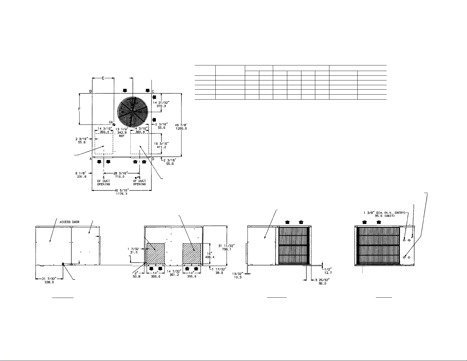
UNIT CHARACTERISTICS LBS. KG.
ELECTRICAL UNIT WT. CORNER WT. LB./KG. CENTER OF GRAVITY
50NQ018 208/230/1/60 326 148
50NQ024 208/230/1/60
50NQ030 208/230/1/60 356 161 88/40
50NQ036 208/230/1/60 370 168 101/46 108/49 83/38 78/35 20" (508.0)
50NQ042 208/230/1/60 375
334 152
A B
100/45
102/46 63/29
102/46 108/49 63/29
103/47 89/40 76/34 21-1/4" (615.9) 22-3/4" (577.8)
170 102/46 112/51
UNIT TOP
..............................................
DUCT SIDE OF UNIT...6 MIN. CONTROL BOX ACCESS SIDE
SIDE OPPOSITE DUCTS.........................30 BOTTOM OF UNIT
NOTE. PROVISION MUST BE MADE FOR FRESH AMBIENT AIR TO REACH THE OUTDOOR
COIL WITHOUT RECIRCULATION OF THE AIR FROM THE OUTDOOR FAN DISCHARGE.
EVAP COIL
ACCESS PANEL
D E F
C
61/26 17-1/2" (444.5) 24-1/2" (622.3)
60/27
76/34 19-3/4" (501.6) 23-1/2" (596.9)
85/39
50NQ REQUIRED CLEARANCES CINCHES)
48 BLOWER ACCESS PANEL SIDE...........................................30
17" (431.8)
24" (658.6)
24" (658.6)
.............................................
...............................................................
1 3/8' DIA.CH.V. ENTRY3-
7/8' DIA.CL.V. ENTRY)-
22.2
30
0
35.0 (ACCESSORY
ELECTRIC HEAT)
RIGHT SIDE VIEW
^1 1/4'
31.7
3/4' NPT
19.0
DRAIN OUTLET
7/8' DIA K.O.-^
22.2
ELECT. ENTRY
ALT.
f
U-2 5/16 SQ.
3 25/32 -»1
96.0
LEFT SIDE VIEW FRONT VIEW
-
---------------------
58.7 TYP
38 3/8'
974.7
Fig. 2—Dimensional Drawing—Small Cabinet
Page 3
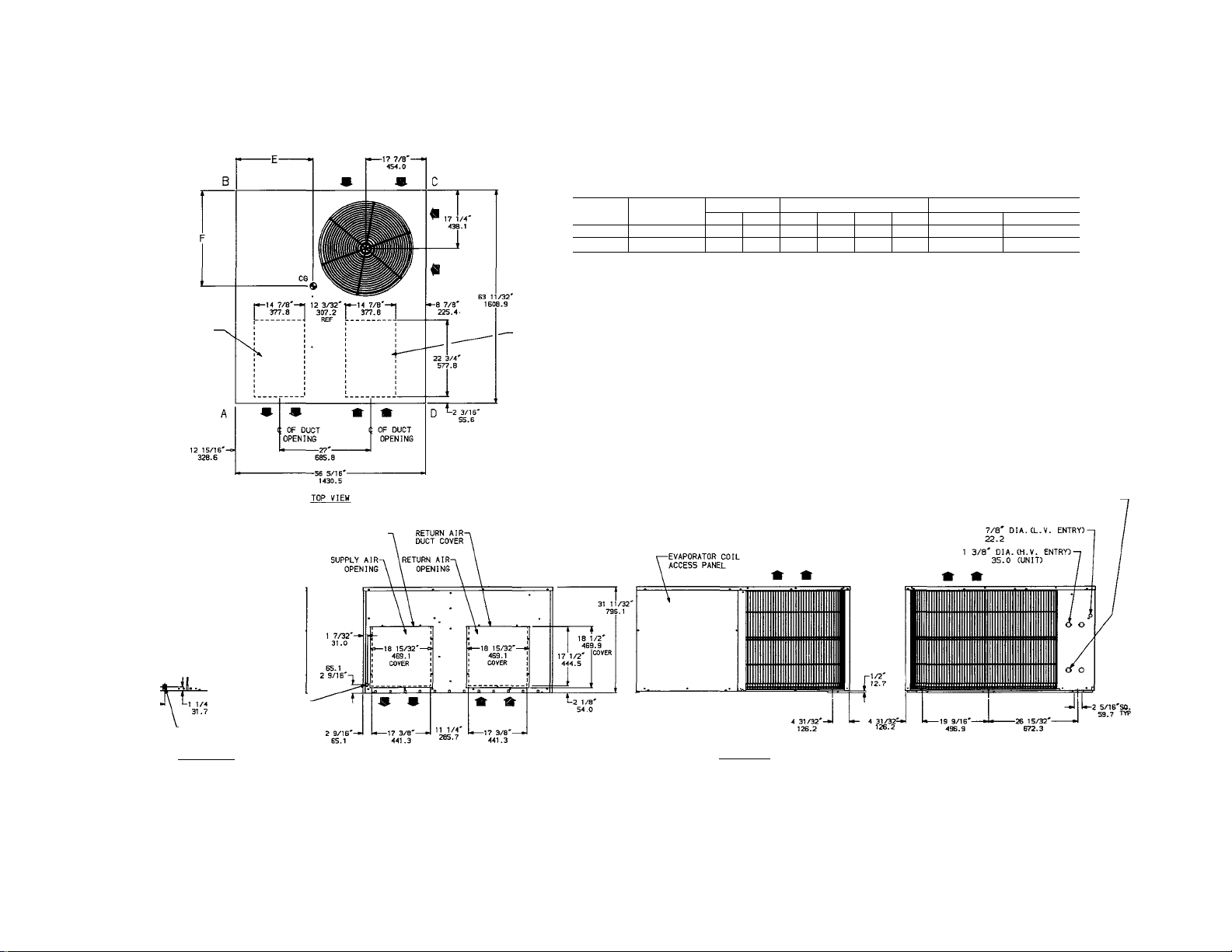
UNIT
50NQ048 208/230/1/60 450 204
50NQ060 208/230/1/60
LBS. KG.
483
ELECTRICAL UNIT WT.
CHARACTERISTICS
A B C
120/54 147/67 101/46
219 128/58
CORNER WT. LB./KG. CENTER OF GRAVITY
170/77 106/48 80/36 21-1/2" 546.1 27-1/2" 698.5
82/37
D
E
22-3/4" 577.8 28-1/4" 717.5
F
CO
OPTIONAL SUPPLY-
-CONTROL BOX
ACCESS DOOR
AIR OPENING
3/4 NPT
19.0
DRAIN OUTLET
RIGHT SIDE VIEW
-BLOWER ACCESS
DOOR
7/8' DIA. K.O.-
22.2
ALT. ELECT. ENTRY
SUPPLY AIR
DUCT COVER
-OPTIONAL RETURN
AIR OPENING
50NQ REQUIRED CLEARANCES (INCHES)
UNIT TOP
..............................................
DUCT SIDE OF UNIT...6 MIN. CONTROL BOX ACCESS SIDE
SIDE OPPOSITE DUCTS
NOTES PROVISION MUST BE MADE FOR FRESH AMBIENT AIR TO REACH THE OUTDOOR
COIL WITHOUT RECIRCULATION OF THE AIR FROM THE OUTDOOR FAN DISCHARGE.
........................
LEFT SIDE VIEW
48 BLOWER ACCESS PANEL SIDE........................................30
30 BOTTOM OF UNIT
............................................
..............................................................
1 3/8' DIA.(H.V. ENTRY)-
30
0
35.0 (ACCESSORY
ELECTRIC HEAT)
Fig. 3—Dimensional Drawing—Large Cabinet
Page 4
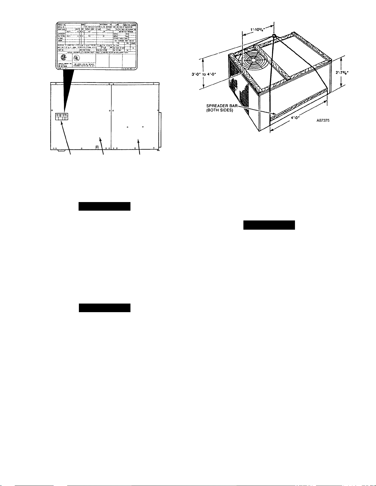
Fig. 5—Suggested Rigging
RATING CONTROL BOX BLOWER
PLATE ACCESS DOOR ACCESS
Fig. 4—Rating Plate Location
Step 1—Moving and Setting Unit in Piace
DOOR
A CAUTION
Use spreader bars and crate top when rigging the unit
to be lifted. Model 50NQ must be rigged for lifting as
shown in Fig. 5. Use extreme caution to prevent dam
age when moving the unit. Unit must remain in an
upright position during all rigging and moving opera
tions. The unit must be level for proper condensate
drainage; therefore, the ground-level pad or accessory
roof-mounting curb must be level before setting the
unit in place. When a field-fabricated support is used,
ensure that the support is level and properly supports
the unit.
ROOFTOP INSTALLATION
A CAUTION
When installing the unit on a rooftop, be sure that the
roof will support the additional weight. Refer to Figs. 2
and 3 for total weight and corner weight information.
For downflow applications, an accessory roof-mounting
curb may be installed on, and flashed into the roof before
unit installation. The instructions for installing the acces
sory curb are packaged with the curb.
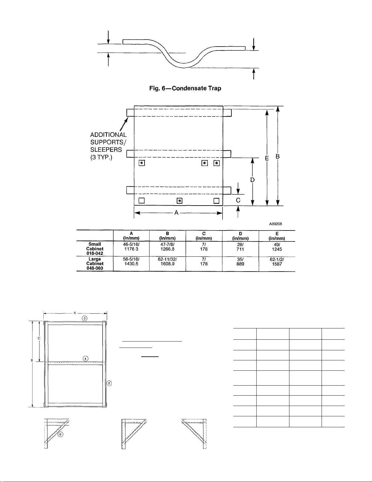
For end-discharge applications place the unit on a level base
that provides proper support. Refer to Fig. 7 for location of
additional supports/sleepers. On flat roofs, be sure that the
unit is located at least 4 ins. above the highest expected
water level on the roof to prevent flooding.
GROUND-LEVEL INSTALLATION
Place the unit on a solid, level, concrete pad that extends
approximately 2 ins. beyond the casing on all four sides of
the unit. Do not secure the unit to the pad except when
required by local codes. Ensure pad does not obstruct coil
drainage holes in bottom of unit. (Holes drain water during
cooling and defrost cycles.) In areas where prolonged sub
freezing temperatures or snowfall occur, increase clearance
to 12-18 ins. by constructing an angle-iron frame to support
the unit. The frame should be designed so as not to block
the drainage holes. See Fig. 8 and Table 1 for recommended
frame construction. Extend a 24-in. gravel apron around
pad for condensate and defrost water drainage.
CLEARANCES
The required minimum operating and service clearances are
shown in Figs. 2 and 3. Adequate condenser air must be
provided.
A CAUTION
Do not restrict condenser airflow. An air restriction at
either the outdoor-air inlet (the entire surface of the out
door coil) or the fan discharge can be detrimental to
compressor life.
The condenser fan discharges through the top of the unit.
Ensure that the fan discharge does not recirculate to the
condenser coil. Do not locate the unit in either a corner or
under a complete overhead obstruction. The minimum clear
ance under a partial overhang (such as a normal house roof
overhang) is 48 ins. above unit top. The maximum horizon
tal extension of a partial overhang must not exceed 48 ins.
Do not locate the unit where water, ice, or snow from an
overhang or roof will damage or flood the unit by falling on
the top. Do not locate the unit where grass, shrubs, or other
plants will interfere with the airflow either into or out of the
unit. Do not install the unit on carpeting, tile, or other com
bustible material other than wood flooring. Heat pump may
be installed on wood flooring or on Class A, B, or C roof cov
ering materieds.
Step 2—Condensate Disposal
NOTE: Ensure that condensate-water disposal methods
comply with IoceJ codes, restrictions, and practices.
Model 50NQ disposes of condensate water through a 3/4-in.
NPT drain fitting. See Figs. 2 and 3 for location.
Install a 3-in. trap at the dredn fitting to ensure proper
drainage. See Fig. 6. Meike sure that the outlet of the trap is
at least 1 in. lower than the unit drain pan connection to
prevent the pan from overflowing. Prime the trap with
water.
If the installation requires draining the condensate water
away from the unit, connect a drain tube using a minimum
of 7/8-in. OD copper tubing, 3/4-in. gedvemized pipe, or
3/4-in. plastic pipe. Do not undersize the tube. Pitch the
Page 5
1" MIN.
2" MIN.
A88130
♦These embossments are located on Large Cabinet Units (048-060 size only.)
Fig. 7—Additional Support/Sleeper
Location
©I" -------------®' I ~ I I
^ _j Ui_i/2" (38mm)
®^" — I
0 —ZZT—j
MATERIAL;
ANGLE IRON - 1-1/4" (31 8mm) TO 1-1/2" (38mm) COMM’L STD
WELD FRAME TOGETHER
PAINT WITH ZINC-RICH PAINT (RUSTPROOF)
—I [—1-1/2" (38mm)
Table 1—Mounting Frame
Dimensions
Large Cabinet
Item No.
A 50 in
B 60-1/2 in
C 30-1/4 in
1
2 60 in
3 49-1/2 in
4 49-1/2 in
5
Length
(1269mm)
(1535mm)
(766mm)
12 in (305mm)
to
24 in (610mm)
(1523mm)
(1257mm)
(1257mm)
16 in
(406mm)
Small Cabinet
Length
40-3/8 in
(1024mm)
47 in
(1193mm)
23-1/2 in
(597mm)
12 in (305mm)
to
24 in (610mm)
46-1/2 in
(1181mm)
39-7/8 in
(1012mm)
39-7/8 in
(1012mm)
16 in
(406mm)
Quantity
—
—
“
4
2
2
1
8
Fig. 8—Mounting Frame
Page 6

drain tube downward at a slope of at least 1 in, in every 10
ft of horizontal run. Be sure to check the dreun tube for
leaks.
Condensate water can be drained directly onto the roof in
rooftop installations (where permitted) or onto a gravel
apron in ground-level instaJlations. When using a gravel
apron, make sure it slopes away from the unit.
Step 3—Duct Connections
Model 50NQ has duct flemges on the supply and return mr
openings on the side and bottom of the unit except on sizes
048 and 060. 048 and 060 sizes do not have flanges on side
dischetrge openings. See Figs. 2 and 3 for connection sizes
and locations.
NOTE; The design and insteJlation of the duct system must
be in accordance with the standards of the National Fire
Protection Association for installation of nonresidence-type
air conditioning and ventilating systems, NFPA No. 90A or
residence type, NFPA No. 90B, and/or loced codes and
ordinances.
Adhere to the following criteria when selecting, sizing, and
installing the duct system:
1. Remove appropriate panels from unit to obtain either
horizontal or down discharge. If models 018 through
042 are installed in horizontal discharge applications,
remove side duct covers, save screws, and instedl the
covers on bottom duct openings. To install duct covers
on bottom duct openings, remove one flange which
interferes with heater mounting plate. For models 048
through 060 remove either side or bottom duct covers
as needed and discard.
2. Select and size ductwork, supply-air registers, and
return-air grilles according to ASHRAE recom
mendations. Refer to Tables 2 & 3 for static pressure
capability.
A CAUTION
When the duct-system fastening holes are being drilled
into side of unit instead of the unit duct flanges, use
extreme care to avoid puncturing the coil or coil tubes.
See Fig. 9.
3. Use flexible transition between rigid ductwork and unit
to prevent transmission of vibration. The transition
may be screwed or bolted to duct flemges. Use suitable
gaskets to ensure weather and edrtight seed.
4. Install external, field-supplied air filter(s) in return-air*
ductwork where it is easily accessible for service. Rec
ommended filter sizes are shown in Table 4.
5.
Size all ductwork for maximum required airflow (either
heating or cooling) for unit being installed. Avoid
abrupt duct size increases or decreases.
6.
Adequately insulate and weatherproof all ductwork
located outdoors. Insulate ducts passing through
unconditioned space and use vapor barrier in accor
dance with latest issue of SMACNA and ACCA mini
mum installation standards for heating and air condi
tioning systems. Secure edl ducts to building structure.
Flash, weatherproof, and vibration-isolate £dl openings
7.
in building structure in accordance with local codes and
good building practices.
8.
For Canadian Installations Only—An L-shaped
exhaust duct fabricated of sheet metal or a material
rated 94-5V shall be used in the case of downflow
applications.
Step 4—Electricial Connections
A WARNING
The unit cabinet must have an uninterrupted, unbro
ken, electrical ground to minimize the possibility of per
sonal injury if an electriced fault should occur. This
ground may consist of electrical wire connected to the
unit ground lug in the control compartment, or conduit
approved for electriced ground when instedled in accor
dance with the National Electrical Code ANSI/NFPA70 (in Canada, Canadian Electrical Code CSA C22.1)
and loced electriceil codes.
A CAUTION
A failure to follow these precautions could result in
damage to the unit being installed:
1. Meike all electrical connections in accordance with the
latest National Electrical Code, ANSI/NFPA-70 and
local electrical codes governing such wiring. In Canada,
all electrical connections must be in accordance with
CSA standead C22.1 Canadian Electrical Code part 1
and applicable local codes. Refer to Unit Wiring
Diagram.
2. Use only copper conductor for connections between
field-supplied electrical disconnect switch and unit. DO
NOT USE ALUMINUM WIRE.
3. Ensure that high-voltage power to unit is within oper
ating voltage range indicated on unit rating plate (Fig.
4). On 3-phase units, ensure that phases are voltage
and current balanced. Consult local power company for
correction of improper voltage and/or phase balance.
4. Insulate low-voltage wires for highest voltage con
tained within conduit when low-voltage control wires
are run in same conduit as high-voltage wires.
5. Do not damage internal components when drilling
through any panel to mount electriceil hardware, con
duit, etc.
CAUTION: DO NOT DRILL
OR SCREW IN SHADED AREA
«
SUPPLY
INLET/OUTLET PANEL
Cabinet Size
Smaii Cabinet
018-042
Large Cabinet 21-1/4"
048-060
Fig. 9—Location of Coii Area-
Not to be Drilied
5 0"-
RETURN
A
20-1/2"
O
Page 7

HIGH-VOLTAGE CONNECTIONS
The unit must have a separate electrical service with a field-
supplied, waterproof disconnect switch mounted at, or
within sight from the unit. Refer to the unit rating plate
(Fig. 4) for meiximum over-current device size and minimum
circuit amps (ampacity) for wire sizing.
The field-supplied disconnect switch box may be mounted
on the unit over the high-voltage inlet hole in the control
corner panel. See Figs. 2 and 3.
Proceed as follows to complete the high-voltage connections
to the unit:
1. Connect ground lead to chassis ground connection
when using separate ground wire.
2. Run high voltage leads into unit through inlet hole in
control box post, and to contactor through the hole in
the bottom of control box. The high voltage leads
should remain in conduit until entering control box and
a watertight termination should be made at bottom of
control box.
SPECIAL PROCEDURES FOR 208-V OPERATION
A WARNING
Make sure that the power supply to the unit is switched
OFF before making any wiring changes. Electrical
shock can cause personal injury or death.
For operation of 208 volts, disconnect the yellow
transformer-primary lead from the contactor. See the unit
wiring label. Remove the tape and cover from the termined
on the end of the blue tremsformer-primeiry lead. Save the
cover. Connect the blue lead to the contactor terminal from
which the yellow lead was disconnected.
Using the cover removed from the blue lead, insulate the
loose terminal on the yellow lead. Wrap the cover with elec
trical tape so that the metal terminal cannot be shorted.
Indoor blower motor speed taps should be changed for 208V
operation on 208/230v rated units. Interchange motor lead
at blower motor. See “Start-up and Adjustments” section
(page 9) and unit wiring label.
CONTROL VOLTAGE CONNECTIONS
Locate the room thermostat on an inside wall in the space to
be conditioned where it will not be subjected to either a cool
ing or heating source or direct exposure to sunlight. Mount
the thermostat 4 to 5 ft above the floor.
Use No. 18 AWG color-coded, insulated (35 C minimum)
wires to make the control voltage connections between the
thermostat and the unit. If the thermostat is located more
than 100 ft from the unit (as measured along the control
voltage wires), use No. 16 AWG color-coded, insulated (35 C
minimum) wires.
A grommeted control voltage inlet hole is located in the
panel adjacent to the control access panel. See Figs. 2 and 3.
Run the low-voltage leads from the thermostat, through the
inlet hole, and to the control voltage terminals. Connect the
thermostat leads to the terminals as shown in Fig. 10.
HEAT ANTICIPATOR SETTING
Factory thermostats have fixed heat anticipator settings.
No adjustment is required.
CIRCUIT BREAKER
Unit has manual reset circuit breaker which is located in the
low-voltage wiring box adjacent to low-voltage terminal
board. If unit fails to operate, first check breaker for tripped
position. If breaker is tripped, re-set and try to start unit. If
breaker continues to trip there is a problem in the lowvoltage electrical circuit (electrical short, ground, or tremsformer overload). Correct the condition and check for nor
mal unit operation.
PREPARING UNIT FOR START-UP
A WARNING
Failure to observe the following warnings could result
in serious personal injury:
1. Follow recognized safety practices and wear protec
tive goggles when checking or servicing refrigerant
system.
2. Do not operate compressor or provide any electric
power to unit unless compressor termined cover is in
place and secured.
3. Do not remove compressor terminal cover until edl
electrical sources have been disconnected.
4. Relieve all pressure from system before touching or
disturbing anything inside compressor termined box
if refrigerant leak is suspected eiround terminals.
5. Never attempt to repair soldered connection while
refrigerant system is under pressure.
6. Do not use torch to remove any component. System
contains oil and refrigerant under pressure. To
remove a component, wear protective goggles and
proceed as follows:
a. Relieve all pressure from system.
b. Cut component connecting tubing with tubing
cutter and remove component from unit.
c. Ceirefully unsweat remaining tubing stubs when
necessary. Oil can ignite when exposed to torch
flame.
PRESTARTUP PROCEDURES
Proceed as follows to inspect and prepare the unit for initial
startup:
1. Remove all access panels.
2. Read and follow instructions on all WARNING, CAU
TION, and INFORMATION labels attached to, or
shipped with, unit.
3. Make the following inspections:
a. Inspect for shipping and handling damages such as
broken lines, loose parts, disconnected wires, etc.
b. Inspect for oil at all refrigerant tubing connections
and on unit base. Detecting oil generally indicates a
refrigerant leak. Leeik-test all refrigerant tubing
connections using electronic leak detector, halide
torch, or liquid-soap solution. If refrigerant leak
is detected, see “Refrigerant Leaks” section on
page 9.
c. Inspect all field- and factory-wiring connections. Be
sure that connections are completed and tight.
d. Inspect coil fins. If damaged during shipping and
handling, carefully straighten fins with a fin comb.
4. Verify the following conditions:
a. Make sure that outdoor fan blade is correctly posi
tioned in fan orifice. Blades should clear fan motor
by no more than 1/4 in. The fan blade hub should be
flush with end of motor shaft.
b. Meike sure that air filter(s) is in place.
c. Make sure that condensate drain pan and trap are
filled with water to ensure proper drainage.
Page 8

THERMOSTAT
8 SUBBASE
(SEE BELOW)
UNIT
CONTROL WIRING
TERMINAL BOARD
THERMOSTAT
a SUBBASE
UNIT
CONTROL WIRING
TERMINAL BOARD
&
&
0-
0
-
B-
[£>
0-
COOLING AND ONE-STAGE HEATING
THERMOSTAT
a SUBBASE
(without Electric Heater)
UNIT
CONTROL WIRING
TERMINAL BOARD
0)
-<D
0)
<8>
-B)
ODT — Outdoor Thermostat
HR — Heater Relay
COOLING AND TWO-STAGE HEATING
(Unit equipped with Electric Heater, Supplemental
Heat, One Outdoor Thermostat)
THERMOSTAT
a SUBBASE
UNIT
CONTROL WIRING
TERMINAL BOARD
COOLING AND TWO-STAGE HEATING
(Unit equipped with Electric Heater, Supplemental
Heat, No Outdoor Thermostats)
Fig. 10—Control Connections
HR — Heater Relay
ODT — Outdoor Thermostat
COOLING AND TWO-STAGE HEATING
(Unit equipped with Electric Heater, Supplemental
Heat Relay, Two Outdoor Thermostats)
Page 9

d. Make sure that all tools and miscellaneous loose
parts have been removed.
Unit is now ready for initial steirtup.
REFRIGERANT LEAKS
Proceed as follows to repair a refrigerant leak and to charge
the unit:
1. Locate leak and ensure that refrigerant system pres
sure has been relieved.
2. Repeiir leak following accepted practices.
NOTE: Install a filter-drier whenever the system has been
opened for repair.
3. Add a small charge of R-22 refrigerant vapor to system
and leak-test unit.
4. Evacuate refrigerant system if additional leaks are not
found.
5. Charge unit with R-22 refrigerant, using a volumetriccharging cylinder or accurate scede. Refer to unit rating
plate for required charge. Be sure to add extra refriger
ant to compensate for internal volume of filter-drier.
START-UP AND ADJUSTMENTS
A CAUTION
Complete the required procedures given in “Preparing
Unit for Start-up,” page 7, before starting the unit.
Do not jumper any safety devices when operating the
unit.
Do not operate unit in the cooling mode when the out
door temperature is below 55 F (unless accessory lowtemperature kit is installed).
Do not operate unit in heating mode when outdoor tem
perature is above 60 F.
Do not rapid-cycle the compressor. Allow 5 minutes
between “on” cycles to prevent compressor damage.
The unit compressor is equipped with a crankcase heater. It
is recommended that heater be energized a minimum of 24
hours before starting unit. To energize heater only, set ther
mostat at OFF position; turn on unit main power at discon
nect switch.
TO START UNIT—Check that main power is on and that
compressor crankcase heater has been energized for at least
24 hours.
1. Check that heater main power is on as applicable.
2. Set selector switch at OFF.
3. Set fan switch as desired (FAN) (AUTO.).
4. Set thermostat dial at the desired temperature.
5. Set selector switch at HEAT or COOL. Check system
refrigerant charge as described in “Checking Charge”
section below.
CHECKING CHARGE-Factory Charge is shown on unit
rating plate (See Fig. 4).
A CAUTION
Compressor damage may occur if system is over
charged.
Adjust charge in cooling mode by following procedure
shown on the “superheat charging tables” located on unit.
Check charge in heating by following procedure shown on
“heating check chart” located on unit.
Page 10

INDOOR AIRFLOW AND AIRFLOW ADJUSTMENTS
A CAUTION
For proper operation, the recommended airflow is 375
to 450 CFM for each 12,000 BTUH of rated cooling
capacity. Minimum airflows may be different if supple
mental electric heaters are installed. See Table 5.
These units have direct-drive blower motors. Blower motors
are factory-connected to deliver the proper heating and cool
ing airflows at normal external static pressures.
Tables 2 and 3 show both heating and cooling airflows at
various external static pressures. Refer to these tables to
determine the airflow for the system being insteilled. See
Table 4 for the rated heating and cooling airflows.
NOTE: Be sure that all supply- and return-eur grilles are
open, free from obstructions, and adjusted properly.
A WARNING
Disconnect electrical power to the unit before changing
blower speed. Electrical shock can cause personal
injury or death.
The heating and/or cooling airflow of 208/230-V direct-drive
blower motors cem be changed by changing the lead connec
tions at the blower motor. The motor leads are color-coded
as follows:
black = high speed
blue = medium speed
red = low speed
UNIT CONTROLS
All compressors have the following internal-protection
controls:
1. High-pressure Relief Va/ue—This valve opens when the
pressure differential between the low and high side
becomes excessive.
2. Compressor Overload—This overload interrupts power
to the compressor when either the current or internal
temperature become excessive, and automatically
resets when the internal temperature drops to a safe
level. This overload may require up to 60 minutes (or
longer) to reset; therefore, if the internal overload is
suspected of being open, disconnect the electrical
power to the unit and check the circuit through the
overload with an ohmmeter or continuity tester.
SEQUENCE OF OPERATION
COOLING—On a call for cooling, thermostat makes circuit
R-0, R-Y and R-G. When room temperature rises to within 2
degrees of control setting of thermostat, circuit R-O makes,
energizing reversing valve solenoid (RVS). Unit is now in
standby condition for cooling. As room temperature rises,
the second-stage bulb makes, allowing a circuit (R-Y)
through low-pressure switch (LPS) to contactor (C), starting
compressor (COMP) and outdoor fan motor (OFM). Circuit
R-G energizes indoor fan relay (IFR) starting indoor fan
motor (IFM).
When thermostat is satisfied, contacts open de-energizing
contactor. Indoor fan relay, compressor and motor stop.
HEATING—On a call for heat, thermostat makes circuits
R-Y and R-G. Circuit R-Y is completed, allowing circuit
through low-pressure switch (LPS) to contactor (C), starting
compressor (COMP) and outdoor fan motor (OFM). Circuit
R-G also is completed, energizing indoor fan relay (IFR) and
starting indoor fan motor (IFM).
Should room temperature continue to fall, circuit R-W is
made through second-stage thermostat bulb. If optional
electric heat package is used, a sequencer is energized bring
ing on first bank of supplemental electric heat. When ther
mostat is satisfied, contacts open, de-energizing contactor
and sequencer. Motors and heaters de-energize.
DEFROST—Defrost board (DB) is a time/temperature con
trol which includes a field-selectable time period between
check if defrost is necessary (30, 50 and 90 minutes). Elec
tronic timer and defrost cycle start only when contactor is
energized and defrost thermostat (DFT) is closed.
Defrost mode is identical to cooling mode except outdoor
fan motor stops and a bank of optional electric heat turns
on to warm air supplying the conditioned space.
CARE AND MAINTENANCE
To ensure continuing high performance, and to minimize the
possibility of premature equipment failure, periodic mainte
nance must be performed on this equipment. This combina
tion heating/cooling unit should be inspected at least once
each year by a queilified service person.
NOTE TO EQUIPMENT OWNER: Consult your local Dealer
about the aveulability of a maintenance contract.
A WARNING
The ability to properly maintain this equipment
requires certain expertise, mechanical skills, tools, and
equipment. If you do not possess these, do not attempt
to perform any maintenance on this equipment other
than those procedures recommended in the Users Man
ual. A FAILURE TO HEED THIS WARNING
COULD RESULT IN SERIOUS PERSONAL
INJURY AND POSSIBLE DAMAGE TO THIS
EQUIPMENT.
The minimum maintenemce requirements for this equipment
are as follows:
1. Inspect Eur filter(s) each month. Clean or replace when
necessary.
2. Inspect cooling coil, drain pan, and condensate dreiin
each cooling season for cleanliness. Clean when
necessary.
3. Inspect blower motor and wheel for cleanliness each
heating and cooling season. Clean when necessary.
4. Check electrical connections for tightness on controls
for proper operation each heating and cooling season.
; Service when necessary.
A WARNING
A failure to follow these warnings could result in seri
ous personal injury.
AIR FILTER
A CAUTION
Never operate the unit without a suitable air filter in
the return-air duct system. Always replace the filter
with the same dimensional size and type as originally
installed. See Table 4 for recommended filter sizes.
Inspect air filter(s) at least once each month and replace
(disposable-type) or clean (cleemable-type) at least twice dur
ing each heating and cooling season or whenever the filter(s)
becomes clogged with dust and lint.
10
Page 11

Table 2—Models 50NQ Air Delivery (Cfm) in 208V-Horizontal Fiow Set-up at indicated
Externai Static Pressure & Voltage (Sizes 018, 024,030, 036, 048, 060)
UNIT
SIZE
018
024
VOLT/PHASE/HZ
208/1/60
208/1/60
030 208/1/60
036
208/1/60
042 208/1/60
048 208/1/60
060 208/1/60
MOTOR
SPEED
LOW
MED
HI
LOW
MED
HI
LOW
0.0 0.1 0.2 0.3
788 761 758
1195t
1184t 1160t
1425t 1375t 1359t
802 787 772 738
1211t
1473t
1200t 1190t 1169t 1138t
1444t 1418t 1377t 1339t
—
— — — —
MED 1225 1220 1211
HI 1483 1470 1450 1415
LOW
MED
HI
LOW
—
1421 1388 1343 1306
1882f
—
MED 1421
HI
1882t 1809t 1722t 1644t 1546T
— —
1809f
—
1388
1722t 1644t 1546t
1343 1306
LOW 1603 1584 1489
MED 2035 1985
HI
LOW
MED
HI
2304t 2262t 2139t
— — —
2205t 2198t 2190t 2188t 2122t
25811
2538t 2455t 2382t 2305t 2258t 2168t
1923 1851 1771 1678 1497
EXTERNAL STATIC PRESSURE—INCHES W.C.
734
1121t
675
1092t
1308t 1248t 1139t 1030t
702
0.4
0.5
644
987t
—
1061t
1260t
1177 1166 1105 1040
1372 1319
_
—
1252 1165
1386 1296
— —
_
1252
— — — — —
1386
— —
2046
1940
—
1815 1687
2084 2020
0.6
600
886
0.7 0.8 0.9 1.0
564
744
917t
525
724 667
786
—
702 647
— — — — —
993t
1195t
878
997t
913 —
1245
—
1058
1098 891
— — — —
_
1225
— —
1296
1225
__
—
1462
— — —
1943
2084
768 —
838 750
— — —
_
_
— —
_
_ _
—
__
1054
— — —
— — —
_
1863
1992
__
— —
—
1893
581
—
—
—
—
—
—
—
__
—
—
—
Tabie 3—Modeis 50NQ Air Deiivery (Cfm) in 230-V Horizontai Fiow Set-Up at indicated
External Static Pressure & Voltage (Sizes 018, 024, 030, 036, 048, 060)
UNIT
VOLT/PHASE/HZ
SIZE
018 230/1/60
024 230/1/60
030 230/1/60
MOTOR
SPEED
LOW
MED
HI
LOW
MED
HI
LOW
0.0
0.1
913t 905t
1366t 1336t
1584t
1552t
0.2 0.3 0.4
891 848 827 765 699
1302
1467t 1414t 1332t 1256t 1146t
950t 935t 926t
1414t 1399t 1373t 1333t
1652t
1614t
1556T
937 933 929 919 893
MED 1425 1413 1391 1358
HI
1670t 1576t 1552t 1533t
LOW 1088 1075 1050
036 230/1/60
042 230/1/60
048 230/1/60
MED
HI
LOW
MED
HI
1636t 1599t 1553t
2034t 1957t 1846t 1734t
—
1636t 1599t 1553t
2034t
LOW 1891
MED
HI
2230t 2155t
2385t 2304t 2183t
—
—
1957t 1846t 1734t
1852
1819 1746
2060
LOW 2027 2000 1993 1972 1940 1872
060
230/1/60
MED
HI
2546t 2508t 2448t
2837t 2758t
2652t
Air deliveries based on unit dry coil without air filter or optional electrical heaters. Deduct field supplied air filter and electric heater pressure drop to
obtain external static pressure available for ducting. Dashes indicate less than minimum airflow and coil icing may occur.
tAirflow exceeds maximum coil velocity. Condensate may be blown off of coil.
If supplemental electric heaters are used, refer to Table 5 for minimum air-flows. These airflows will be slightly greater than those required for unit
operation.
EXTERNAL STATIC PRESSURE—INCHES W.C.
0.6
1250t
1201t
900 885
0.5
1098t 982t
811 733
1289t 1229t 1148t
1520t
1440t 1375t 1277t
—
— — — —
1326 1268 1196
1468 1419 1324
—
—
1480 1393 1275
—
1602T
— —
1480 1393
1602f
1684
1989t
1885 1782
2097 1982
2382t
2297t 2234t 2150t
1571t
1275
1571t
1553
1863 1717
—
1158
1316
— —
1316
_
1630
—
2587t 2476t 2392t 2304t
0.7 0.8 0.9 1.0
651 606 575
898 776 676 609
101 Of
825 750 665
700 — — —
1015t
1098t
1071
811 747
876 799 701
875
— —
1134 920 875 —
1050
1225
1225
__
1483
1614
—
— —
—
1072
_
—
—
— __
— —
1493
— — —
_
— —
_
2070 1977 1870
2224t
2089 2003 1872
—
—
_
—
—
—
—
—
—
—
_
_
Table 4—Rated Airflow and Filter Sizes
Model
Size
Rated Airflow (Cfm)*
018300 024300 030300 036300 1 036500 1 036600 042300 1 042500 | 042600
675 900
1100
1300
Recommended Min f
Field Supplied
Filter Size
324 432 540 648
Disposable Type
Cleanableor High-
Capacity
216 288
360
432
♦Rated in accordance with U.S. Government D.O.E. test procedures and/or ARI Standard 210.
tRequired filter areas shown are based on the larger of the ARI-rated cooling or heating airflow at a velocity of 300 ft/min for disposable type or
450 ft/min for high-capacity type.
50NQ
048300 1 048500 | 048600
1500 1750
756
504 576
060300 1 060500 1 060600
864
11
2100
1030
720
Page 12

SIZE
AIRFLOW
(CFM)
Table 5—Minimum Airfiow for Safe
Electric Heater Operation
018
600
024 030 036 042 048 060
800 1000
1200
1400
1600 2000
Tabie 6—Wet Coil Pressure Drop
Unit Size Wet Coil P.D. (In. wc.)
018, 024 0.54
030 .060
036 .070
042 .075
048
060 .100
.086
UNIT TOP REMOVAL
A CAUTION
Condenser fan and motor eire fastened to the unit top.
When removing the top, use extreme care not to pull
the fan motor leads loose.
NOTE: When performing maintenance or service proce
dures that require removal of the unit top, be sure to per
form all of the routine maintenance procedures that require
top removal, including; coil inspection and cleaning, and
condensate drain pan inspection and cleaning.
Only qualified service personnel should perform mainte
nance and service procedures that require unit top removal.
Refer to the following top removed procedures:
1. Remove all screws that secure unit top, including
screws around four sides and those on top that screw
into internal divider panels. Save all screws.
2. Tape edl side panels at each seam near unit top. Use
tape strips that are at least 5 ins. long to prevent sides
from falling when top is removed.
3. Lift top from unit carefully. Set top on edge and ensure
that top is supported by unit side that is opposite duct
(or plenum) side.Use extreme care to prevent damage to
the fan blades, motor, and insulation.
4. Carefully replace and secure unit top to unit, using
screws removed in step 1, when maintenance and/or
service procedures are concluded. (Be sure to use origi
nal screws that have rubber washers to seal out water
when securing top to internal divider panels.)
INDOOR BLOWER AND MOTOR
For longer life, operating economy, and continuing effi
ciency; clean accumulated dirt and grease from the blower
wheel and motor annually.
A WARNING
Disconnect and tag electrical power to the unit before
cleaning the blower assembly. Failure to adhere to this
warning could cause personal injury or death.
Clean the hlower assembly as follows:
1. Remove and disassemble blower assembly as follows:
a. Remove blower access door.
b. Disconnect blower motor leads from their termina
tion points at motor. Disconnect yellow lead from
control box at capacitor.
c. Remove blower assembly from unit. Be careful not
to tear insulation in blower compartment.
d. Ensure proper reassembly by marking blower wheel
and motor in relation to blower housing before
disassembly.
e. Loosen setscrew(s) that secures wheel to motor
shaft, remove screws that secure motor mount
brackets to housing, and slide motor and motor
mount out of housing.
2. Remove and clean blower wheel as follows:
a. Ensure proper reassembly by marking wheel orien
tation and cutoff plate location.
b. Remove screws holding cutoff plate, and remove
plate from housing.
c. Lift wheel from housing. When handling and/or
cleaning blower wheel, be sure not to disturb bal
ance weights (clips) on blower wheel vanes.
d. Remove caked-on dirt from wheel and housing with
a brush. Remove lint and/or dirt accumulations
from wheel and housing with vacuum cleaner, using
soft brush attachment. Remove grease and oil with
mild solvent.
e. Reassemble wheel and cutoff plate into housing.
f. Reassemble motor into housing. Be sure setscrews
are tightened on motor shaft flats and not on round
part of shaft.
OUTDOOR COIL, INDOOR COIL, AND CONDENSATE
DRAIN PAN
Inspect the coils and condensate drain pan at least once
each year. Proper inspection and cleaning requires the
removal of the unit top. See “Unit Top Removal” section.
The coils are easily cleaned when dry; therefore, inspect and
clean the coils either before or after each cooling season.
Remove all obstructions, including weeds and shrubs that
interfere with the airflow through the outdoor coil.
Straighten bent fins with a fin comb. If coated with dirt or
lint, clean the coils with a vacuum cleaner using the soft
brush attachment. Be careful not to bend the fins. If coated
with oil or grease, clean the coils with a mild detergent-andwater solution. Rinse coils with clear water using a garden
hose. Be careful not to splash water on motors, insulation,
wiring, or air filter(s). For best results, spray outdoor coil
fins from inside to outside the unit. On units with an outer
and inner outdoor coil, be sure to clean between the coils. Be
sure to flush all dirt and debris from the unit base.
Inspect the drain pan and condensate drain line when
inspecting the coils. Clean the drain pan and condensate
drain by removing all foreign matter from the pan. Flush
the pan and drain tube with clear water. Do not splash
water on the insulation, motor, wiring, or air filter(s). If the
drain tube is restricted, clear it with a “plumbers snake” or
similar probe device.
OUTDOOR FAN
A CAUTION
Keep the outdoor fan free from all obstructions to
ensure proper operation. Never place articles on top of
the unit.
12
Page 13

FLARE
NUT
STRAINER
STAMPED ARROW ON
COUPLING BODY
COIL
RUBBER 0-RING
Fig. 11—Metering Device (Duai-Piston) Components
(TOWARD INDOOR COIL)
Inspect the fan blades for cracks or bends each year. Ensure
that blades clear the motor by no more than 1/4 in. The fan
blade hub should be flush with end of motor shaft. If the
blade assembly has slipped down the motor shaft, adjust the
fan position on the motor shaft by loosening the setscrew(s),
then moving the blade assembly up. Be sure that the setscrew(s) is on the flat(s) of the motor shaft before tightening.
ELECTRICAL CONTROLS AND WIRING
Inspect and check the electrical controls and wiring annu
ally. Be sure to turn off the electrical power to the unit.
Remove the control, blower, and compressor compartment
access panels to locate all the electrical controls and wiring.
Check all electrical connections for tightness. Tighten all
screw connections. If any smoky or burned connections are
noticed: disassemble the connection, clean all the parts,
restrip the wire end, and reassemble the connection properly
and securely.
After inspecting the electrical controls and wiring, replace
all the panels. Start the unit and observe at least one com
plete heating cycle and one complete cooling cycle to ensure
proper operation. If discrepancies are observed in either or
both operating cycles, or if a suspected malfunction has
occurred, check each electrical component with the proper
electrical instrumentation. Refer to the unit wiring label
when making these checkouts.
NOTE: Refer to the heating and/or cooling sequence of oper
ation in this publication as an aid in determining proper con
trol operation.
REFRIGERANT CIRCUIT
Inspect Eill refrigerant tubing connections and the unit base
for oil accumulations annually. Detecting oil generally indi
cates a refrigerant leak.
If oil is detected or if low cooling performance is suspected,
leak-test all refrigerant tubing; using an electronic leakdetector, halide torch or liquid-soap solution. If a refrigerant
leak is detected, see “Refrigerant Leaks” in this
publication.
If no refrigerant leaks are found and low cooling perfor
mance is suspected, refer to “Checking Charge” and unit
rating plate.
STRAINER
RETAINER
A87292
INDOOR AIRFLOW
The heating and/or cooling airflow does not require checking
unless improper performance is suspected. If a problem
exists, be sure that all supply- and return-air grilles are open
and free from obstructions, and that the air filter is clean.
When necessary, refer to “Indoor Airflow and Airflow
Adjustments,” page 10 of this publication to check the sys
tem airflow.
METERING DEVICE SERVICING
See Fig. 11 for metering device components. The pistons
have a refrigerant metering orifice through them. The
retainer forms a sealing surface for liquid line flare connec
tion. To check, clean or replace piston:
1. Shut off power to unit.
2. Remove refrigerant from unit using approved refriger
ant removal methods.
3. Remove liquid line flare connections from metering
device.
4. Note position of arrow on metering device body with
respect to unit.
5. Pull retainers out of body. Be careful not to scratch
flare sealing surfaces. If retainers do not pull out eas
ily, carefully use locking pliers to remove retainers.
Replace scratched or damaged reteuners.
Slide pistons out by inserting a small soft wire through
6.
metering hole (18-gauge thermostat wire). See that
metering hole, seeding surface around piston cones and
fluted portion of pistons are not damaged.
Chart on unit access panel illustrates proper arrange
ment and size of pistons.
Clean pistons refrigerant metering orifice.
Replacement retainer 0-ring Part No. is 99CC501052.
LIQUID LINE STRAINER
The Liquid Line Strainers (to protect metering device), are
made of wire mesh and are located in the liquid line on both
sides of the metering device. Strainers are pressed into the
line. Remove strainers by threading a No. 10 sheet metal
screw into strainers and pulling the screw with pliers.
13
Page 14

UNIT SINGLE-PHASE COMPRESSORS are equipped
with a Compressor Start Thermistor (PTC device). When
supply voltage is within 10% limit and compressor does not
start, check the start thermistor with an ohmmeter.
Checking Start Thermistor
1. Shut off all power to unit and wait 10 minutes for
thermistor to cool to ambient temperature.
2. Remove thermistor from circuit.
3. Measure resistance of thermistor with ohmmeter. Nor
mal resistance readings are 12.5 or 25 ohms -I- 20% at
75 F ambient temperature depending on your unit.
4. If ohmmeter resistance reading is not within ± 20%,
the thermistor is defective and must be replaced.
If start thermistor is good and compressor does not steu-t,
disconnect the thermistor from starting circuit and give
compressor a temporeiry capacitance boost. Run compressor
for 10 minutes, then shut off and allow system pressure to
equalize. Reconnect start thermistor and try restarting
compressor without boost capacitor. If after two attempts
the compressor does not start, remove thermistor and add
an accessory start capacitor and relay.
14
Page 15

TROUBLESHOOTING CHART—COOLING CYCLE
DEFECTIVE LOW
VOLTAGE
TRANSFORMER
SUPPLEMENTAL HEAT
RELAY ENERGIZED
OR WIRED WRONG
TROUBLESHOOTING CHART—HEATING CYCLE
LOW LINE VOLTAGE
OK UNBALANCED
3 PHASE LINE
COMPRESSOK
POWER supplì
OPEN
FAULTY START CAP
OR RELAY ISINGLE
PHASE) OR PTC
INDOOR IANS
CVCLINti ON
OVERLOAD
OVERCHARGE OR
NONCONDENSAOLES
IN SYSTEM
RESTHiCTED OR
STUCK
METERING DEVICE
OEFLCIIVE RUN
i;apaciioh
• SINCU E PHASE I
REVERSING VALVE
JAMMED IN MID
POSITION
LOOSE LEADS A
OUTDOOR FAN
MOTOR
INTERNAI FAN
MOTOR KLIXON
OPEN
DEFROST BOARD
N C CONTACTS
OPEN
METERING DEVICE
• RESTRICTED OR
ICE-CLOGGED
UNDERCHARGED
DEFROST T STAT
IN POOR PHYSICAL
CONTACT WITH LINE
DEFECTIVE DEFROST
RELAY OR DEFROST
TIMER
OUTDOOR
THERMOSTAT
DEFECTIVE
CAP TUBE PINCHED
OR BULB NOT
SENSING TRUE ODT
STRIP HEATER RELAY
OR CÜNIACTOH
DETECTIVE
OPENING IN POWER
CIRCUIT TO HEATER
ELEMENTS
OPEN (Kl IXON)
OVERTEMPERATURE
THERMOSTAT
DEFECTIVE ROOM
THEHMOSTAI
|?ND STAGEl
15
BAD ELECTRICAL CON
NECTION ANYWHERE
IN DEFROST CIRCUIT
A88431
Page 16

Manufacturer resenres the right to discontinue, or change at any time, specifications or designs without notice and without incurring obligations.
BookI 1 I 4 PC 101 Catalog No. 565-116 Printed in USA Form 50NQ-1SI Pg 16 7-89 Replaces: New
Tab 15a 15a
 Loading...