

Page 1
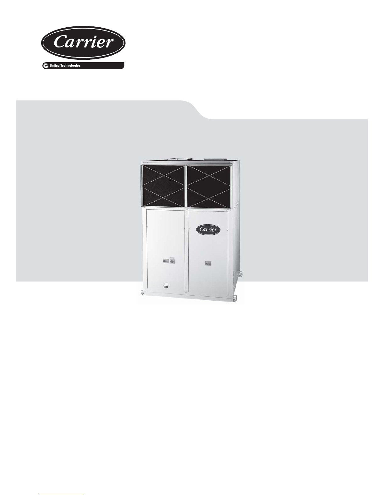
INSTALLATION, OPERATION AND
MAINTENANCE INSTRUCTIONS
50NZ/NF
Nominal cooling capacity 17,9 - 69,6 kW
Nominal heating capacity 18,4 - 73,0 kW
50 Hz
Vertical package air conditionners
Original document
Page 2

2
Vertical package air conditionners
Contents
1. Introduction .........................................................................................................................................................................................................3
2. Operation limits...................................................................................................................................................................................................3
3. Technical characteristics .....................................................................................................................................................................................4
4. Unit identifi cation ................................................................................................................................................................................................5
5. Safety advice ......................................................................................................................................................................................................5
6. Transport .................................................................................................................. ..........................................................................................5
7. Location and assembling .................................................................................................................................................................................... 6
Location designation ........................................................................................................................................................................................ 6
Anchorage for antivibrators .............................................................................................................................................................................. 6
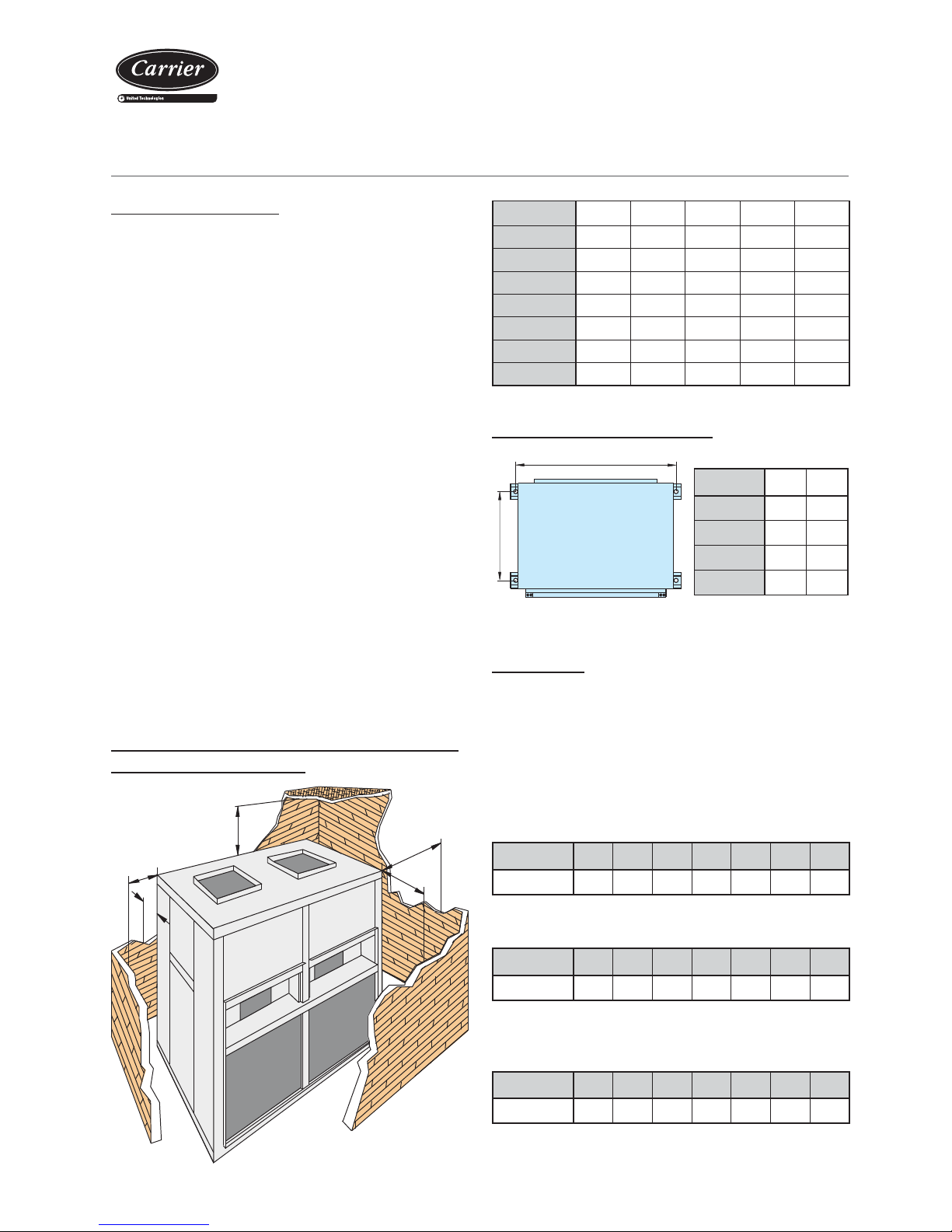
Minimum free space for commissioning and maintenance operations ............................................................................................................6
Sound level .......................................................................................................................................................................................................6
8. Checking before commissioning..........................................................................................................................................................................7
Electrical Connections .......................................................................................................................................................................................7
Air ducts connections ........................................................................................................................................................................................8
Checks at fans ..................................................................................................................................................................................................8
Condensate drain connection ...........................................................................................................................................................................8
9. Safety elements ...................................................................................................................................................................................................9
High pressure pressostat ..................................................................................................................................................................................9
Low pressure pressostat ...................................................................................................................................................................................9
Magnetothermals for line protection .....................................................................................................................................................................9
Automatic switch in the control circuit ...............................................................................................................................................................9
Main door switch ...............................................................................................................................................................................................9
Safeties at the compressor ..............................................................................................................................................................................9
Fans and compressors protection .....................................................................................................................................................................9
Clogged fi lter detector (optional) ......................................................................................................................................................................9
Air quality probe (optional) .............................................................................................................................................................................10
10. Options ............................................................................................................................................................................................................10
Hot water coil ..................................................................................................................................................................................................10
Condensation pressure control .....................................................................................................................................................................10
Electrical heater .............................................................................................................................................................................................10
11. Commissioning ................................................................................................................................................................................................11
Checks prior to commissioning ......................................................................................................................................................................11
Operational checks .........................................................................................................................................................................................11
Possible problems at commissioning ..............................................................................................................................................................11
12. Maintenance ....................................................................................................................................................................................................12
13. Control and analysis of breakdowns................................................................................................................................................................14
Page 3
3
Vertical package air conditionners
1. INTRODUCTION
2. OPERATION LIMITS
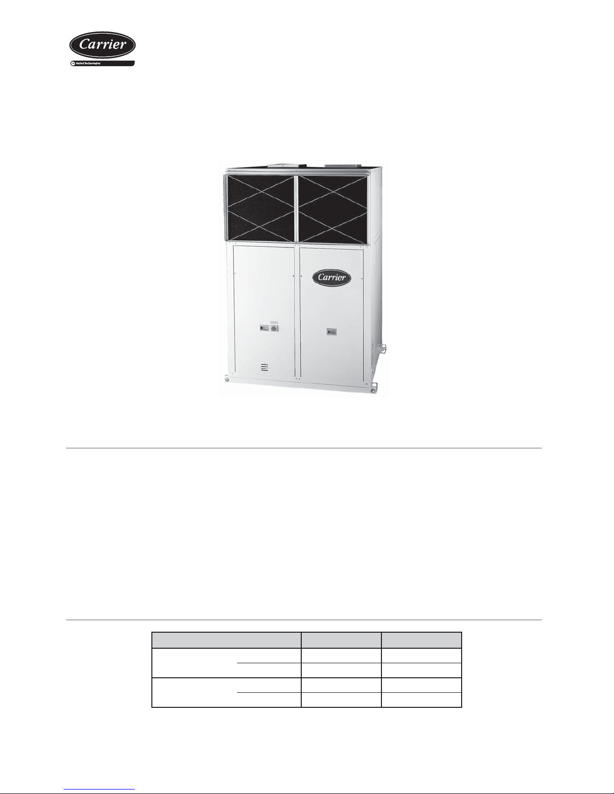
Heat Pumps and Cooling Units 50NZ/NF are Air- Air packaged units
of monobloc vertical compact construction, designed to be installed
indoors, safe from external damages, with access registers to fans,
cooling circuit and electrical panel by means of easily removable panels.
These units are suitable for commercial and industrial applications
where the availability of space allows its installation, since they offer
the advantage of its vertical construction.
• 50NZ Series: Air/air packaged cooling units.
• 50NF Series: Air/air packaged reversible heat pumps.
After their manufacture, all units are charged with refrigerant and
are tested in factory, checking the correct operation of all their
components.
In this manual are described the actions and safety standards to follow
for a correct manipulation of the unit.
With control of operation condensation pressure up to -10ºC.
When the outdoor temperature usually reaches less than 5ºC WB it is recommended installing
a support element.
Conditions air inlet Cooling Heating
Indoor coil
Minimum
14 ºC WB 10 ºC
Maximum
21 ºC WB 27 ºC
Outdoor coil
Minimum
12 ºC -7 ºC WB
Maximum
43 ºC 15 ºC WB
Page 4
4
Vertical package air conditionners
Cooling capacity given for indoor temperature conditions 27ºC, 50% RH and 35ºC outdoor temperature.
Heating capacity given for indoor temperature conditions 20ºC and 6ºC WB outdoor temperature.
Total power input by compressor and motorised fans under nominal conditions.
Climatic warming potential of a kilogram of fl uorinated greenhouse gas in relation to a kilogram of carbon dioxide over a period of 100 years.
TECHNICAL CHARACTERISTICS
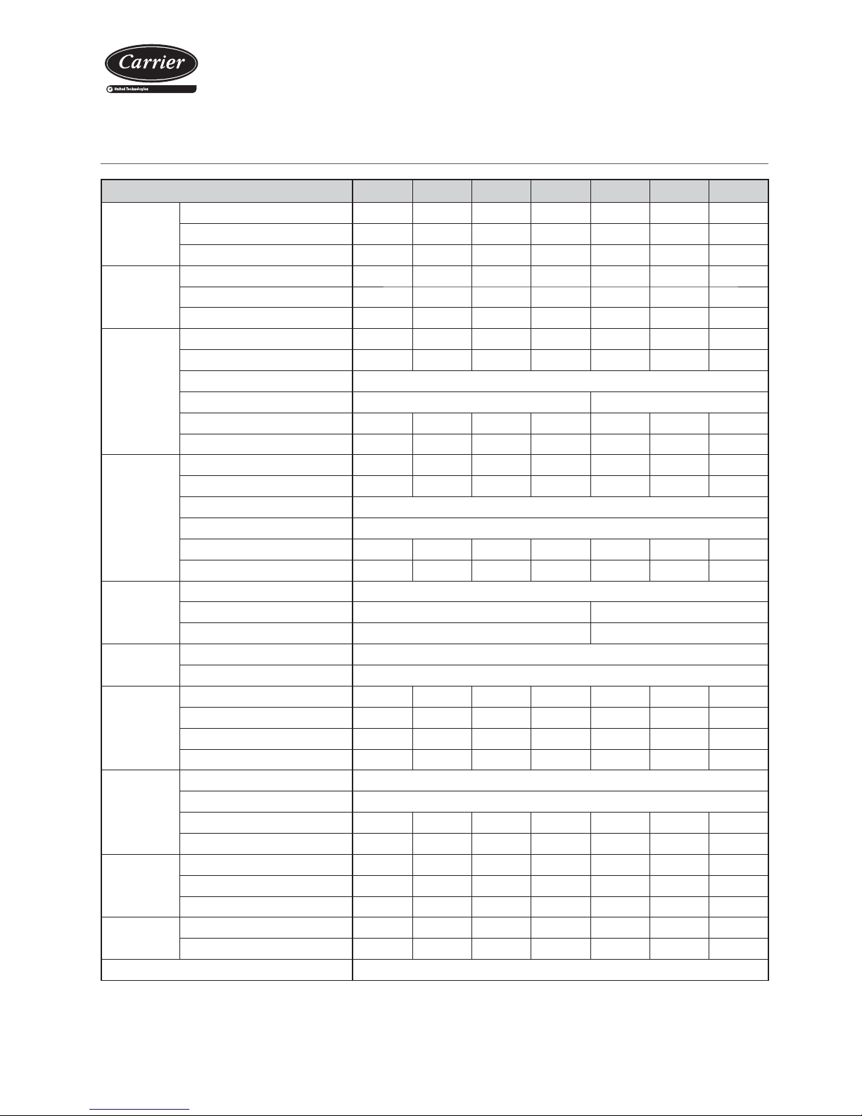
50NZ/NF 80 90 120 160 180 240 320
Cooling
capacities
Cooling capacity
(kW)
17,9 19,3 26,8 34,8 38,6 53,6 69,6
Power input
(kW)
7,3 8,3 11,2 14,2 16,6 22,7 28,5
EER performance 2,5 2,3 2,4 2,5 2,3 2,4 2,4
Heating
capacities
Heating capacity
(kW)
18,4 20,2 27,8 36,5 40,4 55,6 73,0
Power input
(kW)
6,5 7,3 9,5 12,0 14,6 19,3 24,1
COP performance 2,8 2,8 2,9 3,0 2,8 2,9 3,0
Outdoor
circuit
fan
Nominal air fl ow (m
3
/h) 6.500 7.000 10.000 12.200 14.000 20.000 24.400
Available static pressure (mm.w.c) 7 7 13 14 7 13 14
Type Centrifugal
Number 12
Motor output (kW) 1,1 1,5 2,2 3,0 1,5 2,2 3,0
Speed (r.p.m.) 630 680 699 644 680 699 644
Indoor
circuit
fan
Nominal air fl ow (m
3
/h) 4.000 4.600 6.000 7.000 9.200 12.000 14.000
Available static pressure (mm.w.c) 107129 61212
Type Centrifugal
Number 1
Motor output (kW) 0,75 0,75 1,1 1,5 1,5 3 3
Speed (r.p.m.) 941 725 927 644 747 839 697
Compressor
Type Scroll
Compressor number
12
Circuit number 12
Electrical
characteristics
Electrical power supply
400 V / III ph / 50 Hz (±10%)
Power supply
3 wires + ground + neutral
Maximum
absorbed
current
Compressor (A) 17 17 29 29 2 x 17 2 x 29 2 x 29
Outdoor fan (A) 2,7 3,6 5,0 6,9 2 x 3,6 2 x 5 2 x 6,9
Supply fan (A) 2,1 2,1 2,7 3,6 3,6 6,9 6,9
Total (A) 21,8 22,7 36,7 39,5 44,8 74,9 78,7
Refrigerant
Type
R-407C
Global warming potential (GWP)
1.744
Charge (kg)
4,0 5,0 6,4 7,3 10,0 13,0 15,0
Environment impact (tCO2eq)
7,0 8,7 11,2 12,7 17,4 22,7 26,2
Dimensions
Length (mm) 1.174 1.174 1.440 1.440 2.161 2.704 2.704
Width (mm) 885 885 934 934 885 934 934
Height (mm) 1.840 1.840 2.015 2.015 1.840 2.015 2.015
Weight
NZ (kg) 395 402 485 538 725 930 1.048
NF (kg) 410 417 504 558 755 956 1.088
Ø Condensate evacuation 3/4"
Page 5
5
Vertical package air conditionners
Important: The serial number must be used in all
communications regarding the unit.
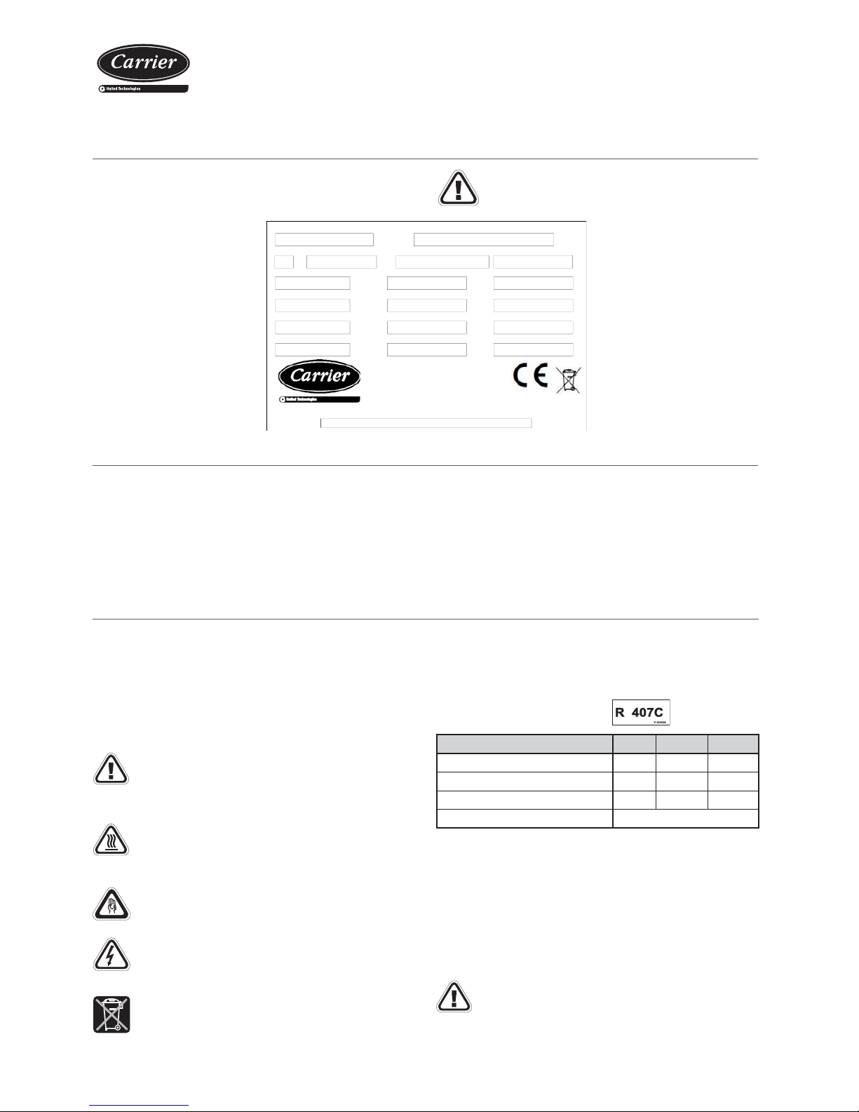
All units bear, legibly and indelibly, a data plate located in a prime
space, with the following data:
4. UNIT IDENTIFICATION
6. SAFETY ADVICE
T o avoid accidents during installation, commissioning or maintenance,
it is required to take into consideration the units specifications:
refrigerated circuits under pressure, refrigerant presence, voltage
presence and implantation.
Because of all of this, only qualifi ed and experienced personnel can
perform maintenance tasks or unit repairs.
It is required to follow the recommendations and instructions
in the maintenance brochures, the labels, and the specifi c
instructions. It is necessary to comply with the norms and
regulations in effect.
V-220005
V-220004
Caution: Before intervening in the unit, verify that the main
power to the unit is cut off. An electric shock can cause
personal damage.
The compressor and line surfaces can reach temperatures
above 100ºC causing burns to the body. In the same fashion,
under certain conditions these surfaces can reach very cold
temperatures that can cause freezing risks.
Use safety gloves and gloves whilst working. Be careful with
sharp parts or elements in the unit.
Note: In order to recycle these units follow the stipulations
of (EC) Directives No.96/2002 and No.108/2003 regarding
electrical and electronic equipment and the management of
the resulting waste.
The unit must be handled with care to avoid transport damage. Thus
we recommend:
- For transport in a container, one must be selected that has an easy
load and unload to the installation location.
- Do not dispose of the pallet nor the packaging materials until the
machine is in its fi nal location.
5. TRANSPORT
- The unit must be lifted and fi xed with care and without inclination
(maximum inclination 15º), since it could harm its operation.
- The unit can be handled with a forklift truck, taking all necessary
precautions to avoid sliding of the unit on the truck’s fork.
- For large dimension units, appropriate transports should be used to
reach the installation location.
These units work with refrigerant gas
R-407C components R-32 R-125 R-134A
Chemical formula CH2F2 CHF2CF3 CH2FCF3
Weight ratio 23% 25% 52%
Unitary global warming potential (GWP) 675 3.500 1.430
Global warming potential (GWP) 1.774
Note: Repair any leak immediately, using a specifi c recovery
unit for R-407C that avoids the transmission of gas to the
atmosphere. It is necessary to drain all the installation and
load at 100%, since it is possible that the mixture has been
decomposed. Charge always in liquid phase.
Refrigerant leaks can cause:
- Displacement of available oxygen, its inhalation can cause
arrhythmias (work must be undertaken in well-ventilated areas).
- Eye irritations can result from contact as well as burns (suitable
safety goggles must be worn).
The climate warming potential (GWP) is the capacity of warming of one
kg of greenhouse-effect fl uored gas relative to one kilogram of carbon
dioxide over a period of 100 years.
Refrigerant leaks:
A periodical check must be performed for refrigerant gas leaks as per
Regulation (CE) Nº842/2006 over certain greenhouse effect fl uoride
gases.
An.Year
CARRIER SCS
Route de Thil
01122 Montluel–France
Tél: 33(0)4 72 25 21 21
Ref. Produit
\Item Nb
r
Designation\Description
Refrigerant kW Absorbee\
Input
Poids\
Weight
Refrigerant kg Tension\Voltage Temperature Maxi C
BP Mini PSM
\MOP
Intensité\Current A
IP
HP Maxi PSM
\MOP
Int. Kit Elect.
No CE
0056
No Serie\Serial Nb
r
No Produit
Contains fluorinated greenhouse gases regulated by the Kyoto protocol
UTC BIS
P.I. Llanos de Jarata
14550 Montilla - SPAIN
Phone: 34 957 65 23 11
Made in Spain
Page 6
6
Vertical package air conditionners
Location designation
Before moving the unit, make sure that all panels are fastened in
place. Lift and lower with care. When choosing the location, in any
way the selected fashion, the following precautions have to be taken
into consideration:
- It is mandatory to comply with norm EN 378-3 on Safety and
Environmental Requirements. Part 3: “In situ” installation and
protection to people.
- It is necessary to check that the structure supports the unit’s weigh
(please see weighs in technical characteristics sheet).
- The area where the unit will be located must be perfectly accessible
for cleaning and maintenance operations. Leave enough space so
that air can circulate around the unit (please check minimum free
space for maintenance).
- Foresee appropriate bumping devices in all the installation so that
noise and vibration transmission is avoided.
For being a unit designed to operate indoor, with ducted discharge
and return, both in the internal circuit as in the external circuit, the
following aspects should be taken into account:
• All models can be installed on the fl oor or over a mount or steel
profi le (in order to avoid the transmission of vibrations, it is
recommended to mount anti-vibratory supports).
• Important: In any case, check that the unit remains perfectly
levelled.
• If in the internal and/or external circuit the air return is not ducted, it
is necessary to provide for grilles of appropriate sizes in the plenum
formed by the roof, forged and walls in order that the circuit makes
the aspiration of the return air.
7. LOCATION AND ASSEMBLING
Anchorage for antivibrators
A
B
Minimum free space for commissioning and
maintenance operations
E
D
A
B
C
Sound level
These units are designed to work with a low acoustic level. In any
case, the design of the installation the outer environment, the kind
of building for the noise transmitted in the air and the solid elements
for the vibration transmission must be taken into consideration for the
acoustic radiation.
If necessary, commission a study to an acoustic technician.
C) The sound pressure level of the unit, with the ducted return and
supply connections, measured at a distance of 5 metres, in open fi eld,
directivity at 2 and 1.5 metres from the ground is:
B) The sound power level in the indoor fan outlet to be taken into
account for the silencer calculation:
A) The sound power level in the outdoor fan outlet to be taken into
account for the silencer calculation:
Note: The sound pressure level depends on the installation conditions
and, as such, is only indicated as a guide.
50NZ/NF A (mm) B (mm)
080 / 090 1.116 695
120 / 160 1.382 744
180 2.103 695
240 / 320 2.646 744
50NZ/NF A (mm) B (mm) C (mm) D (mm) E (mm)
080 1.000 600 900 600 1.500
090 1.200 600 900 600 1.500
120 1.100 750 900 750 1.500
160 1.100 750 900 750 1.500
180 1.200 600 900 600 1.500
240 1.200 750 900 750 2.000
320 1.500 750 900 750 2.000
50NZ/NF 080 090 120 160 180 240 320
dB(A) 74,4 76,3 81,9 83,6 79,3 84,9 86,6
50NZ/NF 080 090 120 160 180 240 320
dB(A) 79,4 75,1 77,5 80,2 77,8 83,1 79,0
50NZ/NF 080 090 120 160 180 240 320
dB(A) 65,7 67,9 71,4 74,0 70,8 75,2 76,0
Note: Diameter antivibration anchoring: 18 mm.
Page 7
7
Vertical package air conditionners
8. CHECKING BEFORE COMMISSIONING
Electrical Connections
Note: Under no circumstance should the unit be started without having read the brochure completely.
Installation norms
T o have electrical power to the unit: wire intake, conductor section and
their calculations, protections, etc..., ask the information provided in this
document (refer to technical characteristic table), the electrical scheme
included with the unit and norms in effect that regulate the installation
of air conditioning units and electrical receivers. Verify that electrical
power supply corresponds to the one on the data plate and that the
voltage remains constant according to the stipulated range.
Check that the electrical connections are correct and tight
(an electrical diagram is included with each unit, along with
its legend).
Note: All connections in the site are the responsibility of
the installer.
T o prevent electrical shocks, make all electrical connections
before energizing the unit. Check that the automatic switch
is closed. Omitting this can cause personal damage. Make
the ground connection before any other electrical connection.
V-220004
V-220005
It is necessary that the wiring of the installation fulfi lls with
the effective legislation. The installer should put elements of
line protection according to the effective legislation.
Electrical heater (optional)
The electrical heaters acquired with the unit will be incorporated to it
modifying the electric panel in the factory to ensure that it is compatible
with the control in the unit.
The electrical heaters requested for units already shipped will be sent
in a kit, and the installer will need to assemble the necessary elements
for the operation of the unit to assemble and for the compliance with the
legal regulations that are applied to the modifi ed unit in terms of safety .
Note: Consult the available capacities in the technical brochure.
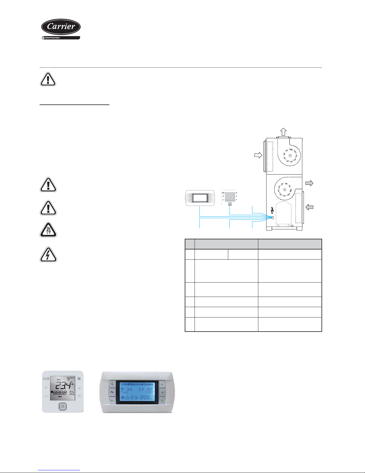
123
456
Outdoor
air circuit
Indoor
air circuit
pGD1 maintenance
terminal
TCO user
terminal
Is necessary that the terminal uses the same power supply that the control
board.
No.
50NZ/NF
080 to 320
1
Power supply 400 III (±10%) 3 + N + GND
2
TCO user terminal connection
(by default it’s installed on the
electric panel)
2 wires for power 230 Vac + 1
shielded cable for communication
type AGW20 / 22 (1braided pair +
drainwire + shielding)
3
pGD1 maintenance terminal
connection
6-wire standard telephone cable
(RJ12 connector)
4
Remote on / off (optional) 2 wires
5
Main alarm signal (optional) 2 wires
6
Electrical heater security
thermistor (opcional)
2 wires (per stage)
This control is basically comprised of a control board, a TCO user
terminal installed on the electric panel, a graphic terminal pGD1
(optional) and sensors.
The pGD1 terminal (optional) facilitates the initial scheduling of
the unit, the modification of the operating parameters and the
description of the alarms produced. This terminal can be installed on
the electric panel, instead of TCO terminal, or with remote connection.
pGD1 terminalTCO terminal
CARRIERrtc basic / medium electronic control
- CARRIERrtc basic version: models 080 to 160
- CARRIERrtc medium version: models 180 to 320
Note: Please refer to this control brochure to obtain more detailed
information about its operation.
Connection chart
Page 8
8
Vertical package air conditionners
The air outlet and return ducts must be calculated in accordance with
the rated fl ow and the unit’s available pressure(refer to the technical
characteristics table). The duct calculation and design must be made
by qualifi ed technical personnel.
It is advisable to take into consideration the following recommendations:
- Bends in the fan discharge outlet must be avoided. It is recommendable
to have a straight section of duct measuring approximately 1 metre. If
it is not possible, they must be as smooth as possible, using indoor
defl ectors when the duct is of large dimensions.
- When making the ducts, direction sharp changes must be avoided
since they can generate occasional pressure drops, which affect
the available pressure and the fl ow. The location of discharge
and aspiration grilles must be studied carefully to avoid the air
recirculation and the transmission and generation of noises to the
interior.
- Flexible connections must be made between the ducts and the unit
that avoid the noise and vibration transmission.
- No matter the type of ducts type to use, they must not be composed
of materials that propagate fi re nor expel toxic gases in the event of a
fi re. The internal surfaces must be smooth and should not pollute the
air that circulates within them. In any case, the effective legislation
about this issue must be respected.
Caution: These units are designed to connect to a duct
network. If the indoor circuit outlet fan is accessible from
a particular point in the duct network, the installer must
fi t a protection mesh in the discharge as per the current
regulation.
Air ducts connections
- Before commissioning, check the blade rotation direction and that
the axis turns without strokes nor vibrations
- Once running, check the operation conditions: pressures, fl ows and
consumptions.
- The coupling of characteristic bends of the fan and the room is
very important, so that the fl ows and pressures provided to the duct
network are as required.
Checks at fans
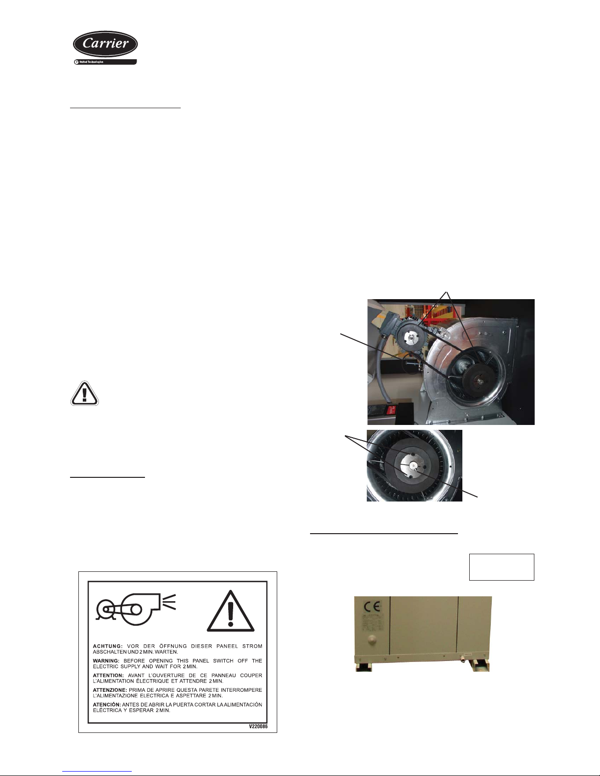
Pulley and belt adjustment
Both for the indoor circuit motorfans as well as the outdoor circuit are
coupled by pulleys and belts. In this type of fans, the following must
be taken into considerations:
- The pulleys must be on the same plane, so it is important to check
them with the help of a ruler or a laser aligner.
- In case they are not aligned, remove the pulley screws, remove the
pulley and, after removing the hub pin, it can be slided over the axle
(this action can be performed both in the motor as well as in the fan).
- After fi xing the pulleys on the same plane, the belt tension is made
by tightening the tensor screw.
- The belt tension must be checked after 24 hours of motor operation.
Attention: Before performing these operations, it is necessary to verify
that the unit is disconnected from mains.
Pulleys must stay on the same plane
Tensor
screw
Pulley
screws
Taper pin
Condensate drain connection
CONNECT SIPHON
METTRE SIPHON
PONER SIFON
V220014
All models are provided of two condensates drain pans, one in the
internal circuit and other in the external circuit,
with independent drainages. Drainage pipe, in
bronze, gas thread M3/4”.
Installation norms
- Check that the condensates outlet is not obstructed.
- All water drain pipes should be provided with a siphon to avoid bad
odours and water overfl ows.
Page 9
9
Vertical package air conditionners
Check the connection air tightness.
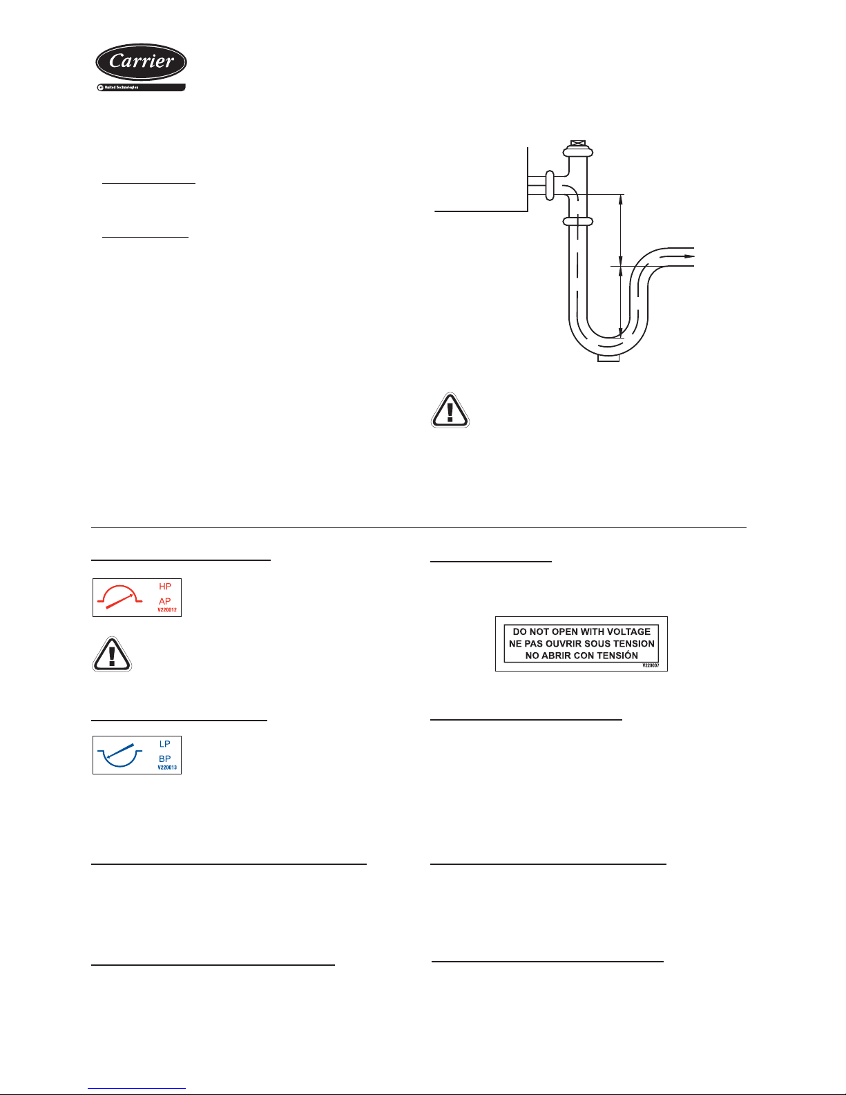
A
Condensates pan
in depression
A
Siphon drain
Slight slope
5/1000
To drainage
Siphon principle scheme
Carry out the assembly of the same one following the attached
principle scheme:
Pan in overpressure:
• It is installed to avoid the access through the drain tubing of bad
smells.
Pan in depression:
• Besides the previous application, the water must be sucked from
the pan.
• For the correct design of the siphon, the dimension “A” should be
at least, the double of the depression to which is the condensates
pan.
• The drain tubing must be slightly sloped to ease circulation towards
the drain.
• To control the drain it is recommended to insert a funnel in the
pipelines toward the drainage.
Note: The original diameter of the tube must be respected. No
reduction can be made.
9. SAFETY ELEMENTS
High pressure pressostat
Connected to the compressor discharge, it will
stop its operation when the pressure at that point
reaches the setpoint. It disconnects at 29 bar
and it is automatically reactivated.
Caution: Threaded and without schrader valve.
Automatic switch in the control circuit
Magnetothermal switch that protects the operation circuit against
continuous surges as well as against high currents of short duration
(short circuits).
Fans and compressors protection
Both the fans and the compressor have a thermal protection for the
motor. Its mission is to protect the motor against an excessive heating
caused by a surge.
Main door switch
By using a mechanical device, it impedes access to the electric panel
when the unit is with voltage. Available in all units.
Low pressure pressostat
When connected to the intake compressor, it
will stop operating when the pressure at this
point drops below the tare value (caused by
obstructions in the circuit, excessive dirt in the
fi lters, fan stop or ice formation in the evaporator). It disconnects at
0.5 bar and resets automatically
Magnetothermals for line protection
They are located at the beginning of the power lines of the compressor
and motorfans to protect them.
Safeties at the compressor
The type compressor that these units as standard have the following
safeties:
- Non-return valve built into the compressor.
- Temperature probe for the discharge from the compressor to protect
the unit with discharge temperatures greater than 135ºC.
Clogged fi lter detector (optional)
Differential pressostat for indication of maintenance to fi lters. Automatic
reactivation.
Page 10
10
Vertical package air conditionners
Electrical heater
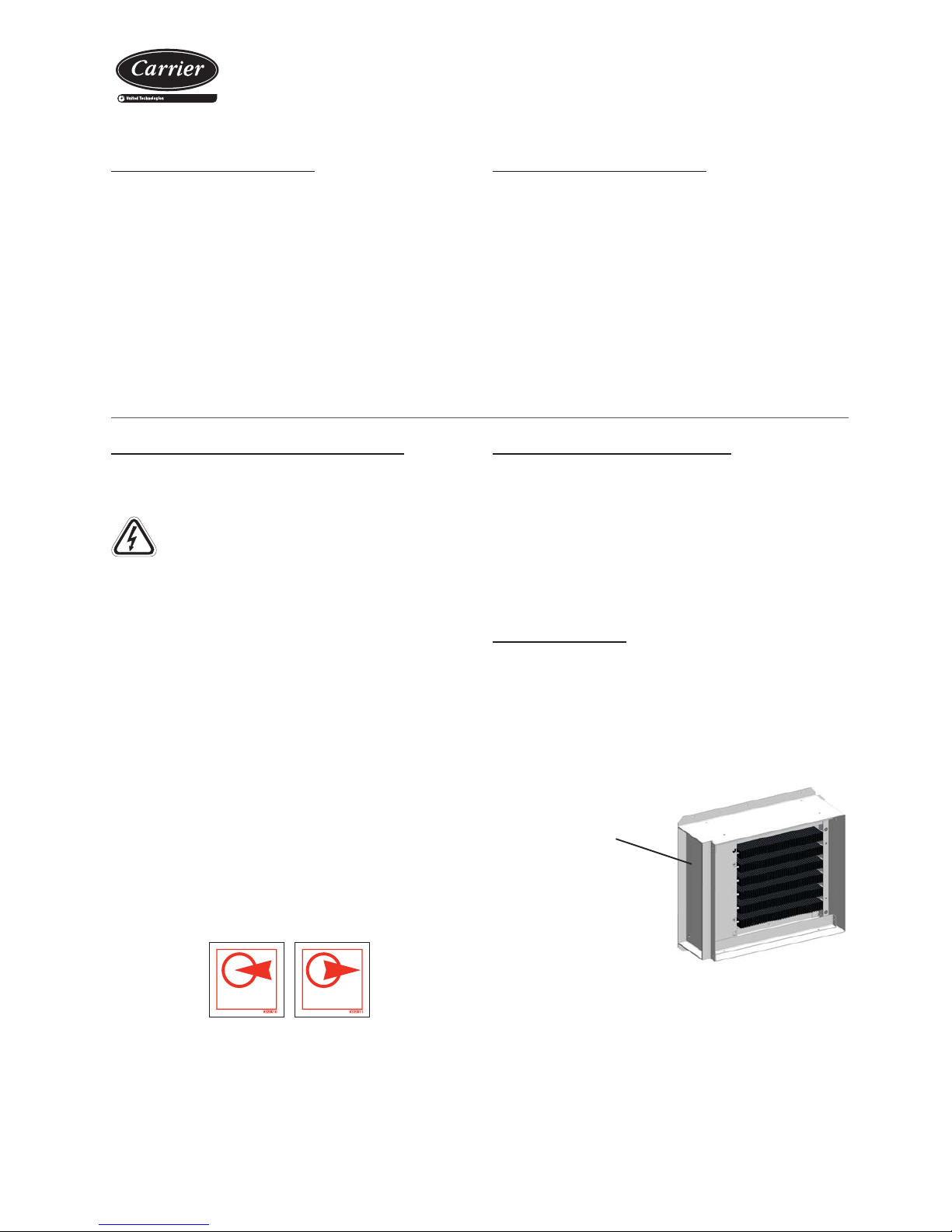
- Important: with this option, the air fl ow controller is compulsory.
- Electric heater assembly in 1 stage, except for 24 kW to 36 kW with
assembly in 2 stages.
- For another stages confi guration, it is necessary to check if it is
possible and the price.
10. OPTIONS
Batería de dos fi las de agua caliente
The installation of some of these options brings in pressure
drops at air level so it needs to be contemplated in the
selection of fans of higher pressure (optional) or in the
substitution of the standard pulley set with a new set that
contributes a higher turn speed to the pad.
The direction of the water fl ow must be correct and so the following
indications must be observed:
V-220004
- Coil fi lling:
• The coil fi lling must be made with the purger open until water runs
through it, which is when it is time to close it.
• Cut off the water supply and let the bubbles generated go up to the
highest coil point, which is the same as the purger, and eliminate
by opening the purger.
• Pour more water into the circuit and repeat the previous steps.
• Activate the water pump (to be foreseen by the installer) and
repeat the previous steps until no air noises are heard in the ducts,
which is when the fi lling of the installation will have been fi nished
successfully.
- In case of long unit stops, and forcibly if they happen in the winter
season, the coil must be emptied.
- Possible water freezing must be avoided: glycolling water or by using
anti-frost thermostat that triggers the circulation pump.
In models 120 and 160 the hot water coil assembly is carried out inside
the unit. In the rest of models the assembly is carried out in duct.
HOT WATERCOIL
BATTERIE D’APPOINT
BATERÍADE APOYO
HOT WATERCOIL
BATTERIE D’APPOINT
BATERÍADE APOYO
Access to the indoor
of the frame through
this lateral panel
In models with two supply outlets (two frames), the electrical heaters
are distributed as symmetrically as possible between both frames.
Condensation pressure control
This control is advisable for units that work in cooling with an outdoor
temperature below 15º C. In units with centrifugal fan a check is
performed per damper in the fan outlet. A servomotor opens or closes
the damper depending on the proportional signal 0-10V received from
the electronic control system.
Air quality probe (optional)
This probe is for installation in the environment or in duct to enable
measuring CO2 and/or volatile compounds.
This probe is to be connected by the client. The clamps on the terminal
board on the main panel used for the connection are indicated on the
wiring diagram provided with the unit.
This probe is supplied inside the main electric panel.
Air fl ow control (optional)
Differential pressostat that measures the fl ow variation in the air outlet.
This allows the detection of fan belt breakages, since the fan relay only
detects operating faults that have arisen in the motor.
This safety device is compulsory in units with electrical heaters.
Page 11
11
Vertical package air conditionners
WICHTIG: WIEDERBEHEIZUNG DER
OLWANNE
IMPORTANT: CRANKCASE HEATING
IMPORTANT: SURCHAUFFE CARTER D’HUILE
IMPORTANTE: RISCALDARE IL CARTER
DELL’OLIO
IMPORTANTE: RECALENTAMIENTO DE
ACEITE DEL CÁRTER
KOENNEN.
TO ALLOW THE COMPRESSOR(S) STARTING
AU PREMIER DÉMARRAGE OU APRÈS UNE ABSCENCE
TENSION 24 HEURES AVANT D’AUTORISER LE
DÉMARRAGE DU(DES) COMPRESSEUR(S).
AL PRIMO AVVIAMENTO U DOPO UNA INTERRUZIONE
PROLUNGATA DELLA ALIMENTAZIONE ELETTRICA,
LASCIARE LA MACCINA SOTTO TENSIONE PER 24 ORE
PRIMA DI AUTORIZZARE L’AVVIAMENTO DEL(DEI)
COMPRESSORE(I).
ANTES DEL PRIMER ARRANQUE O DESPUÉS DE UNA
AUSENCIA DE CORRIENTE POR UN LARGO PERIODO DE
TIEMPO, CONVIENE QUE LA UNIDAD ESTÉ CONECTADA
UN MÍNIMO DE 24 HORAS.
BEIDER ERSTEN INBETRIEBSETRUNZ ORDER NACH EINER
LANGEN STROMUNTER-BRECHUNG BRINGEN SIE DIE
MASCHINE UNTER SPANNUNG 24 STRUNDERLANG
BEVOR SIE DEN(DIE) KOMPRESSOR(EN) EINSCHALTEN
FOR THE FIRSTSTART OR AFTER ALONG TIME OUT OF
VOLTAGE PUT THE MACHINE ON LIVE 24 HOURS BEFORE
DE COURANT PROLONGÉE, METTRE LA MACHINE SOUS
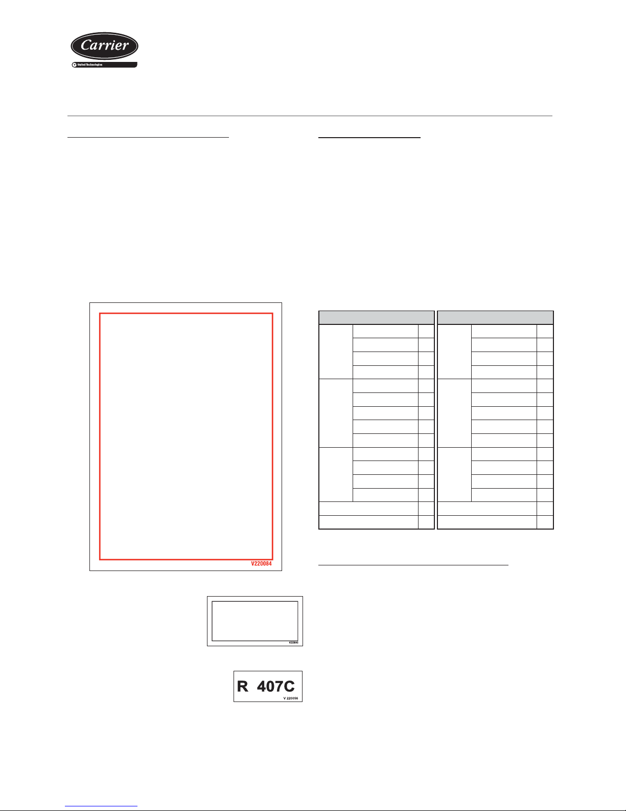
- All models of 50NZ/NF Series are equipped with Scroll compressors
and include a phase control relays.
Check that they rotate in the correct
sense, and if it does not occur, reverse
two wires of the power supply.
- When starting the compressor, check
the undercooling and overheating and thus verify if the refrigerant
charge is appropriate to the operating
conditions. To adjust the refrigerant charge, a
schrader valve is available on the liquid line.
- Verify the absence of any leaks of the
refrigerant.
- Check the unit operation and verify the safety elements.
COMPRESOR SCROLL.
COMPROBAR SENTIDO DE GIRO
COMPRESSEUR SCROLL.
VÉRIFIER LE SENS DE ROTATION
SCROLL COMPRESSOR.
CHECK SENSE OF ROTATION
11. COMMISSIONING
Operational checks
Check the unit operation by verifying the electronic control and the
safety elements.
It is also recommendable to create a report, taking note of the date,
which includes the following information: the nominal voltage, current
absorbed by the compressors, fans and other electrical components,
signifi cant temperatures in the cooling circuit (see table below) and
other aspects considered interesting such as alarms detected by the
electronic control of the unit. The recording of these parameters whilst
the unit is running allows controlling the installation performance and
it is the best possible way to avoid breakdowns since the analysis
of these data makes early detection of anomalies possible or the
provision of the necessary means available to ensure that they do
not take place.
Possible problems at commissioning
All indications given in this brochure must be respected and
complied with to guarantee a correct operation of the units.
Next, several possible operation problems are stated which could
happen if the conditions of the commissioning are not appropriate.
- Air fl ow lack: very high differences between inlet and outlet, originated
by a high pressure drop in the ducts, or by other causes that impede
the correct air circulation.
- Air recirculation in the unit, originated by some obstacle in the air
aspiration or outlet.
- Noise problems because of excessive air fl ow in the grille.
- Water overfl owing to the pan problems, originated by an excessive
fl ow , an incorrect siphon installation or because a defective unit level.
- Refrigerant circuit humidity problem, because of an incorrect vacuum
realization.
Checks prior to commissioning
- It is advisable to make a complete sketch of the installation including
the location of the unit and all the components used. This will be very
helpful for maintenance and repairs to the installation.
- Check that the electrical power supply matches the unit voltage and
that its value lies within acceptable limits.
- It must also be verifi ed that the electric installation has been carried
out according to the electric wiring diagram provided with the unit
(consult the chapter on “Checking before commissioning”).
- Once the above verifi cations have been carried out, the control
circuit is supplied with voltage by the automatic control switch. It is
necessary to leave with voltage the compressor crankcase heater
for 24 hours before starting the compressor.
Cooling MODE Heating MODE
Compressor
Aspiration pressure bar
Compressor
Aspiration pressure bar
Aspiration temp. (1) ºC Aspiration temp. (1) ºC
Condens. pressure bar Condens. pressure bar
Condens. temp. (2) ºC Condens. temp. (2) ºC
Air
condenser
Gas inlet temperature ºC
Air
evaporator
Liquid inlet temp. ºC
Liquid outlet temp. (3) ºC Gas outlet temp. (4) ºC
Air inlet temperature ºC Air inlet temperature ºC
Outdoor temperature ºC Outdoor temperature ºC
Air outlet temperature ºC Air outlet temperature ºC
Air
evaporator
Air inlet temperature ºC
Air
condenser
Air inlet temperature ºC
Air outlet temperature ºC Air outlet temperature ºC
Liquid inlet temp. ºC Gas inlet temperature ºC
Evap. outlet temp. (4) ºC Liquid outlet temp. (3) ºC
Undercooling (2) - (3) ºC Undercooling (2) - (3) ºC
Overheating (4) - (1) ºC Overheating (4) - (1) ºC
Page 12
12
Vertical package air conditionners
12. MAINTENANCE
Recommendations:
Next, some recommendations are stated to perform the cleaning of
the unit’s components:
Air coil
- Check that the coil is free from dust and grease.
- Cleaning the accumulated dust on the coil can be performed with
a vacuum cleaner perpendicular to the fi ns or with a low-pressure
water cleaner. Grease can be removed with water with degreaser.
Do not put stress on the fi ns as they could deform.
Air fi lters
Maintenance:
- Clean usually. Depending on the installation conditions, the fi lter
aspect must be examined to defi ne the cleaning periodicity.
- Gravimetric fi lters. Cleaning the fi ltering mesh can be done with a
household vacuum cleaner, or else by submerging it in water.
- Creased opacimetric fi lters It is necessary to replace them. Foresee
replacement.
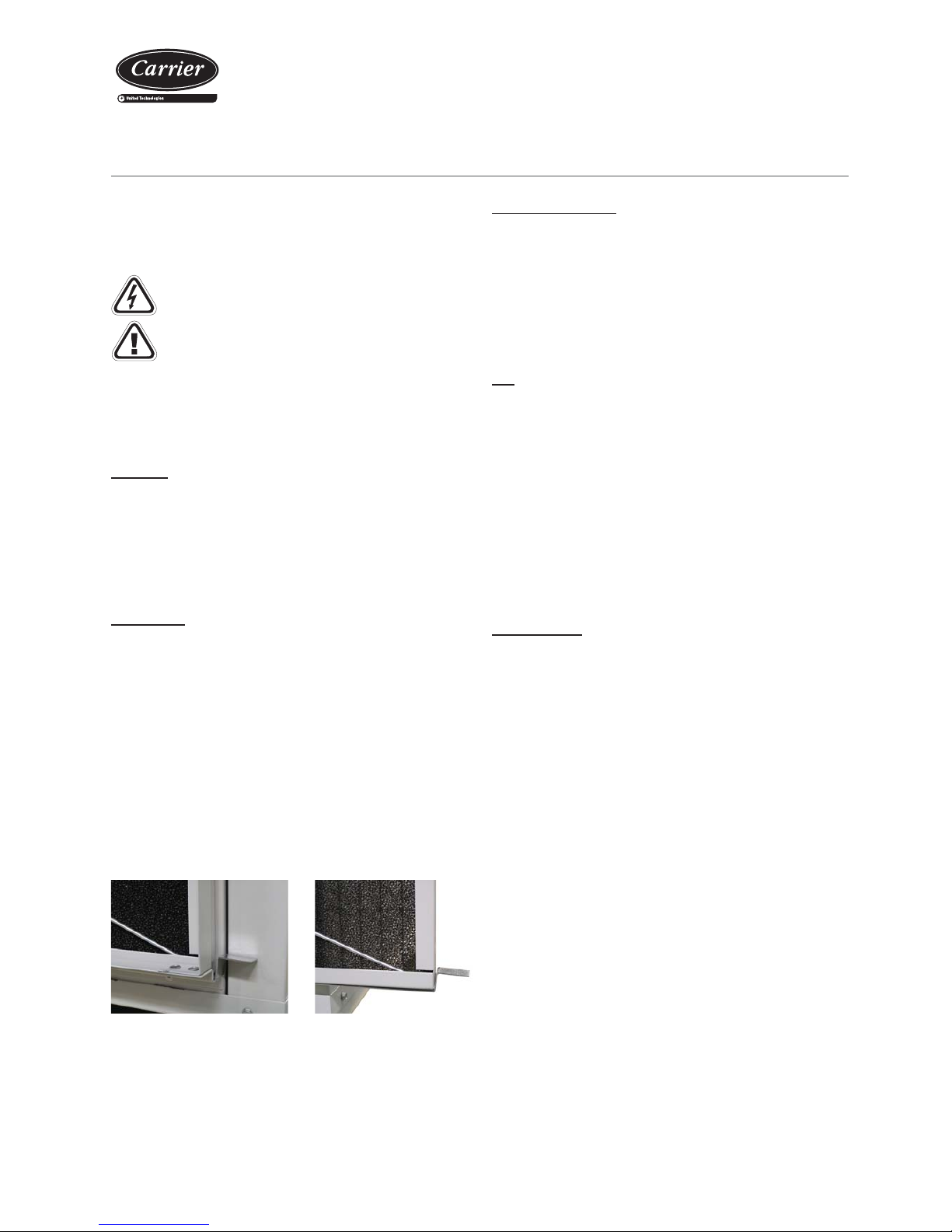
Filters extraction:
- In fi rst place, put the door switch in 0 position.
- In these units, for maintenance operation the extraction of the fi lter
is lateral. Simply, it is carried out the unblocking of the stop-pieces
that fi t the fi lter and it is removed.
Dehydrant fi lter
- The fi lter function is the preserve the cooling circuit clean and without
humidity, neutralizing the acids that can be found in the cooling circuit.
Verify dirt measuring the difference in temperature at the tubing level,
at the inlet and at the outlet of the dehydrant.
- If necessary, replace.
Oil
- Check the oil level and aspect. In case of a colour change, check
the oil quality using a contamination test.
- In the case of the presence of acid, water or metallic particles, replace
the affected circuit oil, as well as the dehydrant fi lter.
- In the event of an oil charge change, only new oil will be used, which
will be identical to the original oil and taken from a can tightly closed
until the moment of the charge.
Note: Both the oil type as well as the volume needed for each model are
stated in the Technical characteristic tables in chapter 3.
Refrigerant
Qualifi ed personnel must perform a periodic control to air tightness
depending on the refrigerant charge, in accordance with the regulation
(EC) No. 842/2006.
It is important not to ever forget that the cooling systems contain liquids
and vapours under pressure.
- All necessary precautions must be taken during the partial opening
of the cooling circuit. This opening entails the discharge of a certain
amount of refrigerant to the atmosphere. It is essential to limit to its
minimum this amount of lost refrigerant by pumping and isolating the
charge in some other part of the circuit.
- The liquid refrigerant at low temperature can cause infl ammatory
injuries similar to burns when contacting the skin or eyes. Always
use protection glasses, gloves, etc. when opening ducts that may
contain liquids.
- The refrigerant in excess must be stored in appropriate containers
and the amount of refrigerant stored at the technical rooms must be
limited.
- Refrigerant barrels and deposits must be handled with precaution
and visible warning signs must be placed to attract attention over
the risks of intoxication, fi re and explosion linked to the refrigerant.
- At the end of its useful life, the refrigerant must be retrieved and
recycled as per the current regulations.
If the return is not ducted, all the set can be removed from the unit
unscrewing the two screws that fi x the panel to the unit and taking it out.
Unit access from all its gates.
V-220004
Caution: Before intervening in the unit, cut off main
power.
The minimal maintenance operations and their periodicity will be made
according to the national regulations.
Any intervention on the electric cooling components must be made by
a qualifi ed and authorized technician.
Page 13
13
Vertical package air conditionners
Centrifugal fans
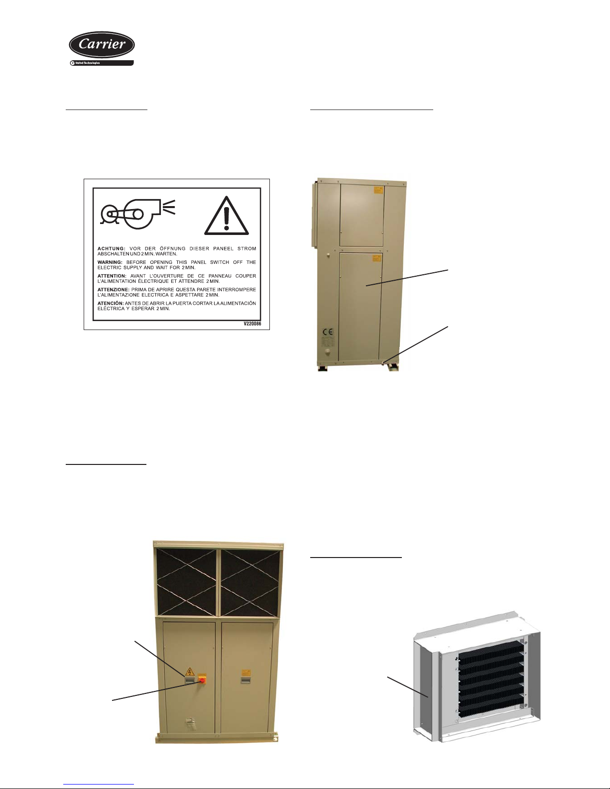
Access:
- In fi rst place, put the door switch in 0 position.
- Later , unscrew the screws that fi x the panels on which we will always
fi nd the sticker:
Recommendations for the maintenance:
- Verify that the turbine and the motor remain clean.
- Foresee having a spare belt set for the fans.
- The motors and the fans have bushings that have been lubricated
and sealed and, thus, do not need further lubrication.
Electrical heaters
A frame with optional electrical heaters can be connected to the supply
outlet of the discharge fan of the internal circuit.
Access to the indoor
of the frame through
this lateral panel
Condensates drain pans
Access:
- Firstly, put the door switch in O position.
- Later, unscrew the screws that fi x the lower panel and take it out.
Recommendations for the maintenance:
- Check that condensates drain pan is clean. As this pan is sloped
towards the drainage, water should not remain stagnant.
- Revise that the drainage is not obstructed.
- Wash the pan with water and non abrasive detergent.
Condensates draining
Access panel to pan
Electrical panel
Access:
- Firstly, put the door switch in O position.
- Later, unscrew the screw that fi x the door of the electrical panel to
the unit.
- Remove the door with the help of a handle.
Access door
to electrical panel
Door switch
Page 14
14
Vertical package air conditionners
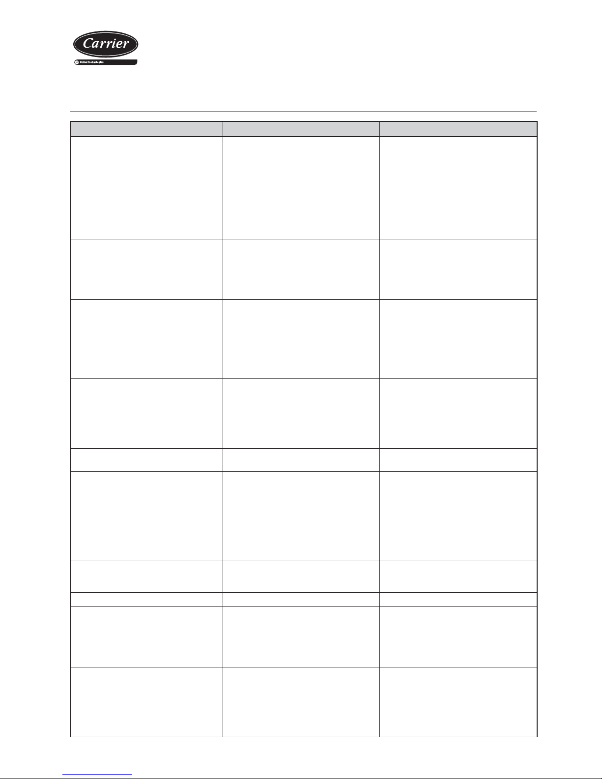
13. CONTROL AND ANALYSIS OF BREAKDOWNS
Symptom Cause Solution
Evaporation pressure very high in relation with
the air inlet
a) Charge excess
b) High air temperature
c) Compressor suction not air tight
d) Cycle reversing valve in middle position
a) Collect refrigerant
b) Verify overheating
c) Verify compressor state and replace
d) Check that the valve is not clogged. Replace if
necessary
Very low condensation pressure a) Gas lack
b) Compressor suction not air tight
c) Cycle inversion valve in middle position
d) Liquid circuit plugging
a) Search for leaks, complete charge
b) Verify compressor state and replace
c) Check that the valve is not clogged. Replace if
necessary
d) Verify the dehydrating fi lter and expansion valve
Condensation pressure very high in relation to
the air outlet, high pressostat cutoff
a) Insuffi cient air fl ow
b) Air inlet temperature very high
c) Dirty condenser (does not exchange)
d) Much refrigerant load (fl ooded condenser)
e) The condenser fan is broken down
f) Air in the cooling circuit
a) Verify the air circuits (fl ow, fi lter cleanliness...)
b) Verify the control thermostat readjustment
c) Clean it
d) Collect refrigerant
e) Repair
f) Make vacuum and load
Evaporation pressure too low (low pressostat
cut-off)
a) Low fl ow in evaporator. Air recirculation
b) Frozen evaporator
c) Liquid line as different temperatures at fi lter inlet
and outlet
d) Gas lack
e) Very low condensation pressure
f) Evaporator fan broken down
a) Verify the air circuits (fl ow, fi lter cleanliness...)
b) Verify defrost
c) Replace fi lter
d) Search for leaks, complete charge
e) Temperature of air or water in condenser very
low (air or water fl ow very high), adjust fl ow
f) Repair
Compressor does not start, does not make
noise (humming)
a) No power
b) The contacts of a control element are open
c) Timing of anti cycle short does not allow the
starting
d) Open contact
e) Contactor coil burnt
f) Indoor klixon open
a) Check differential, fuses
b) Verify the safety chain of the electronic control
c) Verify electronic control
d) Replace
e) Replace
f) Wait for reactivation, verify current absorbed
Compressor does not start, motor sounds
intermittently
a) Electrical power supply very low
b) Power cable disconnected
a) Control line voltage and locate voltage drop
b) Verify connections
Repeated compressor starts and stops a) Because of high pressure
b) Control differential too short (short cycle)
c) Insuffi cient gas, cut-off because of low pressure
d) Dirty or frosted evaporator
e) The evaporator fan does not work, cuts off the
low pressostat
f) Expansion valve damaged or clogged by
impurities (cuts off low pressostat)
g) Dehydrating fi lter clogged (cuts off low safety)
a) Verify charge
b) Increase differential
c) Search for leak, reload unit
d) Clean, verify evaporator air circuit
e) Replace or repair
f) Replace, as well as fi lter
g) Replace
The compressor makes a noise a) Loose attachment
b) Oil lack
c) Compressor noise
a) Fix
b) Add oil to recommended level
c) Replace
Noisy operation a) Unit installed without antivibration protection a) Place base over shock absorbers
Cycle reversing is not carried out:
- No defrosting
- Does not change winter - summer cycles
a) Electrical fault
b) Inversion valve coil defective
c) Defrost method not working
d) Cycle inversion valve in middle position
e) Control fault
a) Locate and repair
b) Replace
c) Verify parameters
d) Tap with running compressor. Replace if
necessary
e) Locate and repair
Alarm or reading error in the humidity probe
(with CARRIERrtc enthalpic electronic control)
a) Dirt in the humidity sensor a) Disassembly the probe encapsule
b) Proceed to clean the sensor with some soft
cotton element and non-abrasive fl uid, without
pressing it
c) Reassemble the casing, checking that the
cable is in contact externally with the metallic
mesh
Page 15

Page 16

Order No.: 10055, 03.2015. Supersedes order No.: New Manufactured for CARRIER in Spain.
The manufacturer reserves the right to change the specifi cation without prior notice. Printed in the European Union.
 Loading...