

Page 1
Number One
Air Conditioning
Maker
e
Division ot Carrier Corporatio
Syracuse New York
Single-Package Heat Pump Units
The 50MQ units are completely self-contained
cooling and heating systems with provision for
addition of accessory electric heaters. They are
air-to-air heat pumps designed for outdoor installa
tion. They may be connected into existing duct
systems which are properly sized and designed to
handle an air quantity of 400 to 500 cfm per ton
of cooling. Required connections include air ducts,
condensate drain, line and control power wiring.
Field-supplied filter must be installed in return air
duct. (See Table 1 for filter size.)
INSTALLER'S PRELIMINARY SURVEY
Step 1 — Inspect Equipment — File claim with
shipping company if shipment is damaged or
incomplete.
Step 2 — Complete or Consider the Following
before installing the 50MQ unit;
a. Consult local building codes for special installa
tion requirements.
b. Provide sufficient space for coil air flow clear
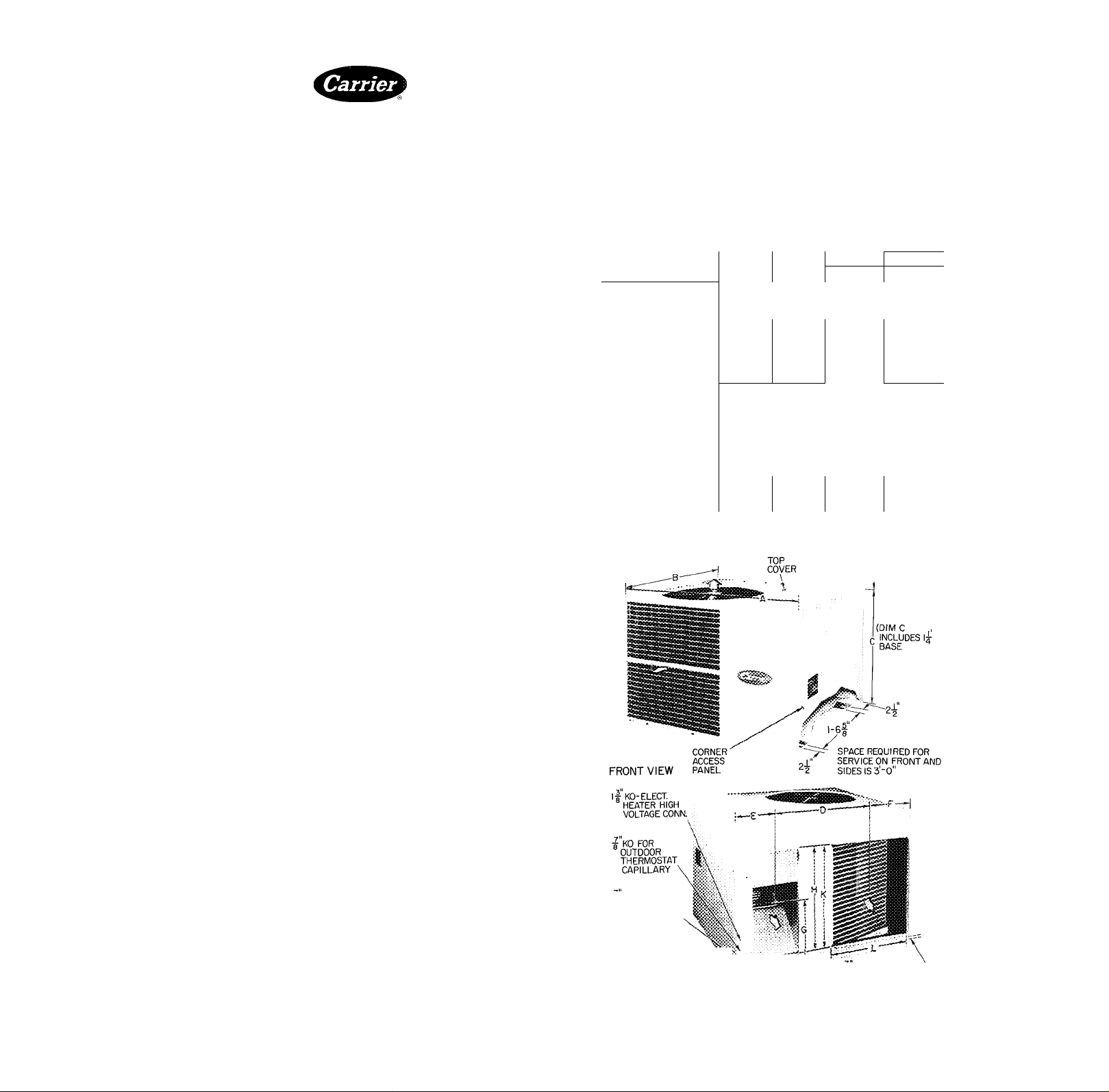
ance, wiring, and servicing unit. (See Fig. 1.)
Table 1 — Installation Data (See Fig. 1.)
UNIT
OPER WT (lb)
DIMENSIONS
{ft-in») A
DUCT CONN.
(ft-in.)
Supply j
Return
FILTER SIZEt (in.)
Disposable
Permanent
‘Dimension "C"
t Recommended
50MQ022 50MQ027 50MQ032
315
B 3-
c*
2- 3Ys
D
1-1OY4
E
0- 6^6
F
0-10“/,6
G
1 -- 1 6
, , H
K
20 X 25
15 X 20
includes 1 1/4-in built-in base support channels (2)
field-supplied filters are 1-in. thick
330 340
2- 3%
1-1OV4
0-
0-10“/,6
1 — 1 6 1 — 1 ^/] 6
Sid e'b y- Si (d€ Rect an gu or
20 X 25 15 X 20(2)
20 X 20 20 X 20
6‘/4
3-
2
2- 3% 2- 7%
1-10^4
0- óV.e
0-10“/Ì6
1- 9%
0-
\QX
1 -
9%
1-
7%
, ,,T
4-0 OVERHEAD AIR
SPACE REQUIRED
50MQ037
353
1-1OY4
0- 6V,6
0-10“,(e
1-
1 5 X 20
20 X 20
20 X 25
c. Locate unit where supply and return air ducts
can be conveniently brought out to unit duct
connections.
d. Unit may be placed with duct side as close to
building as condensate drain, top removal, duct
connections and power connections will permit
Position unit so water or ice from roof will not
drop directly on top of unit or in front of coil
e. Make provisions for condensate drainage and
defrost water disposal. See Mounting Pad and
Cooling Cycle Condensate Disposal.
f. Roof installation method for 50MQ will depend
on building construction and special require
ments of local building codes. Ensure roof will
support unit weight. See Mounting Pad for
details.
a OIAM HOLE-
CONTROL
WIRING CONN
l| DIAM HOLE-UNIT
LINE WIRING CONN „
O SUPPLY AIR
^ RETURN AIR
Certified dimension drawings available on request
REAR VIEW
SPACE REQUIRED FOR SERVICE ON
REAR OF UNIT IS I'-O"
Fig. 1 — Dimensions and Connections
CHANNELS-2)
■g ID SIDE CONDENSATE
DRAIN FITTING
© Carrier Corporation 1974
Form No 50MQ-1SI
Page 2
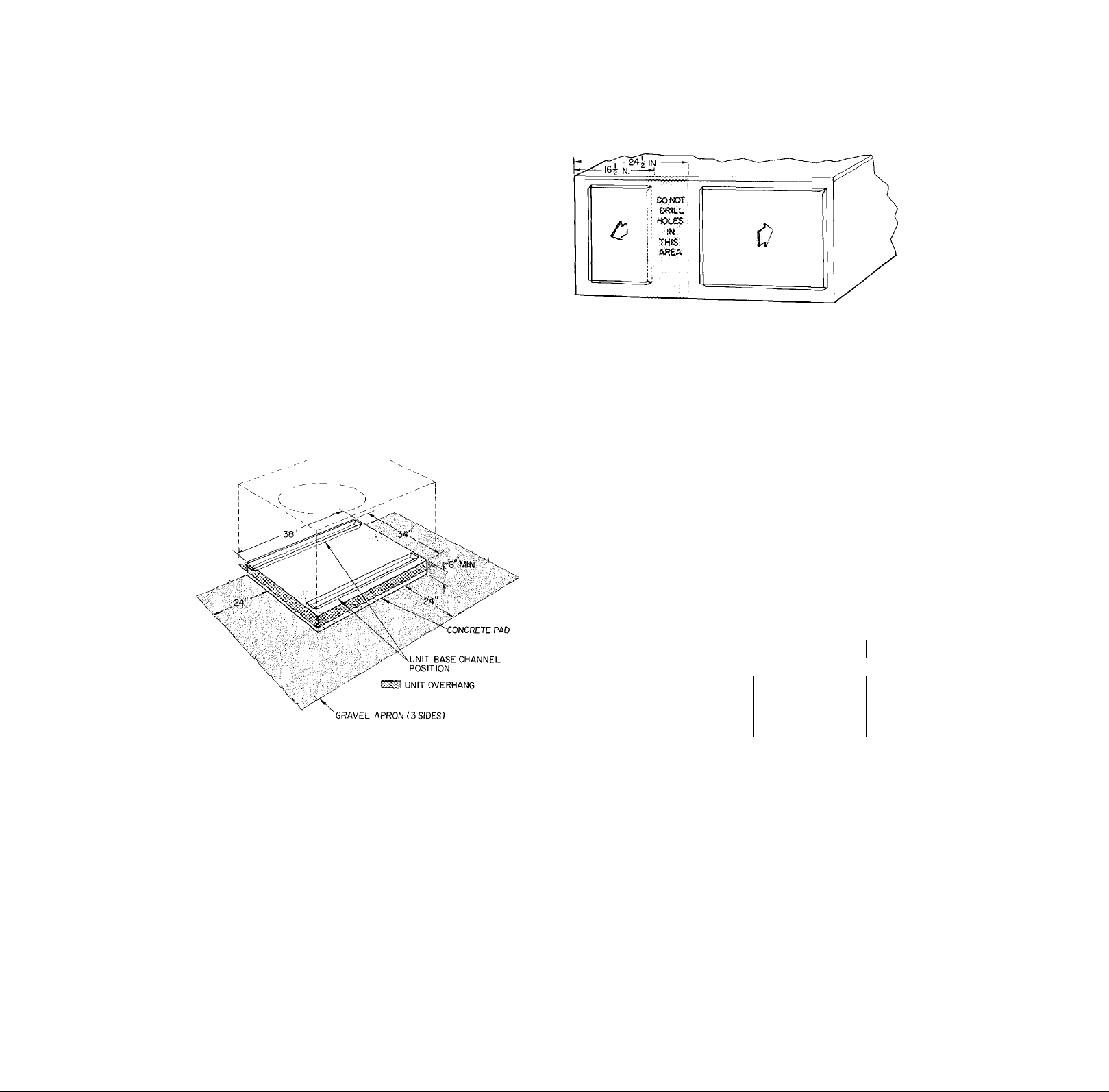
MOUNTING PAD
Step 3 — On the Ground: Mount Unit on a Solid,
Level Concrete Pad. See Fig. 2 for pad dimensions.
Ensure pad does not obstruct coil slots in unit base
pan. (Slots drain water during heating cycle).
Construct pad a minimum of 6 in. thick to provide
clearance under base pan coil slots for drainage and
ice buildup. In areas where prolonged subfreezing
temperatures, drifting or heavy snows occur, in
crease clearance to 12 to 18 inches. If climatic
conditions dictate, construct an angle iron frame to
support unit 12 to 18 in. off concrete base. Cross
angle of frame must not obstruct base pan coil
slots. Extend a 24-in. gravel apron around pad for
condensate and defrost water drainage field.
Step 4 — On the Roof: Mount Unit on a Level
Platform or Frame. Unit must be elevated for
proper clearance as described under ground in
stallation above. Roof design and water drainage
must be planned to prevent unit and its duct
flashing from sitting in water.
for system air duct design. When designing and
installing ductwork, consider the following.
a. When connecting ductwork to unit, do not drill
holes in area shown below. Coil may be
damaged.
b. All units should have field-supplied filters in
stalled in return air ductwork. Recommended
sizes for filters are shown in Table 1.
c Avoid abrupt duct size increases and reductions.
d. Use flexible connectors between ductwork and
unit to prevent transmission of vibration. When
electric heater is installed, use fireproof asbes-
• tos (or similar heat resistant material) con
nector between ductwork and unit discharge
connection. Heat resistant duct connector must
extend 24 in. from electric heater element.
e. Size ductwork for cooling air quantity (cfm).
The minimum air quantity for safe electric
heater operation is;
m
Fig. 2 — Concrete Pad Dimensions
DUCTWORK
Step 5 — Connect Supply and Return Air Ductwork
to unit supply and return air duct connections. Refer
to Fig. 1 and Table 1 for unit supply and return air
connection sizes and locations.
Flanges are provided on unit for rectangular
duct connections. Fig. 3 shows a typical duct
system with 50MQ installed. Do not operate unit
longer than 5 minutes without ductwork. If neces
sary, refer to Carrier System Design Manual, Part 2,
INDOOR
UNIT FAN 5.0
SPEED
50MQ022
50MQ027 Med = H i 900
50MQ032
50MQ037
Med-Lo
Med-Lo
Med-Lo
ELECTRIC HEATER KW
7.5 1 10.0 j 15.0
Cfm
733 733 1
900 I 900
]068 1068 1
1230
1068 Í 1068
1230 ' 1230 j1230
20.0
733 j
-
-
1230
Heater limit switches may trip at air quantities
below those recommended.
f. All external ductwork must be insulated and
weatherproofed. Ducts passing thm uncondi
tioned space must be insulated and covered
with vapor barrier in accordance with the latest
issue of SMACNA’s (Sheet Metal and Air
Conditioning Contractors National Association)
and NESCA’s (National Environmental Systems
Contractors Association) minimum installation
standards for residential heating and air condi
tioning systems.
g. Secure all ducts to building structure. Weather
proof duct openings in wall or roof according
to good construction practices.
Page 3
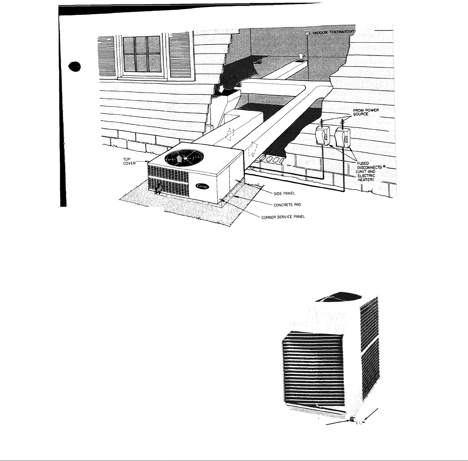
— POWER WIRING
-------
CONTROL WIRING
OUTDOOR air flow
INDOOR AIR FLOW pUMP
«Separate fused disconnect required for electric heater.
Fig. 3 — Typical Installation
COOLING CYCLE CONDENSATE DISPOSAL
Condensate may be drained directly onto gravel
apron or connected by drain line(s) to a dry well
Condensate disposal methods must comply with
local codes and practices.
Step 6 - Connect a Drain Line to rubber conden
sate drain fitting on side of unit (see Fig. 1). Use
clamp provided. Install factory-supplied conden
sate trap (taped to indoor fan housing for ship
ment) at end of drain line. If a drain line is not
used, connect condensate trap to unit drain fitting
as shown in Fig 4.
ELECTRIC HEATER INSTALLATION
For complete heater installation data, including
accessory outdoor thermostat and emergency heat
switch, refer to accessory electric heater Installa
tion, Start-Up and Service booklet. Complete
control wiring connections are shown in this
booklet.
CONDENSATE DRAIN FITTING
WITFI CLAMP
Fig. 4 - Condensate Drain Connection
CONDENSATE
DRAIN TRAP
Page 4
ELECTRICAL DATA AND WIRING
Field wiring must comply with local and
national fire, safety and electrical codes. Voltage to
unit must be within ±10% of voltage indicated on
nameplate. On 3-phase units, phases must be
balanced within 2%.
Operation of unit on improper line voltage or ; with e.xcessive phase unbalance constitutes abuse and is not covered by Carrier Warranty.
See Table 2 for recommended wire and fuse sizes
Step 7 — Install a Branch Circuit Fused Disconnect
of adequate size to handle unit starting current.
Locate disconnect within sight of and readily
accessible from the unit. (Use a separate fused
disconnect(s) for each electric circuit as required.)
Step 8 — Bring Line Power Leads Into Unit.
Extend leads from fused disconnect thru hole pro
vided (Fig. 1) into line wiring splice box (Fig, 5).
Step 9 — Connect Ground Lead to Ground Lug in
Splice Box before connecting power wiring. See Fig.
6. Connect line power leads to yellow and black
pigtails on single-phase units or yellow, blue and
black pigtails on 3-phase units. Use wire nuts
'provided. Tape each connection. Wire nuts are
suitable for copper or aluminum wire since they
contain joint compound.
Step 10 — Set Indoor Fan Motor Speed — (Refer
to page 2 for minimum allowable air quantity for
safe electric heater operation). Four-speed indoor
fan motor is factory wired for high speed opera
tion. Fan motor is equipped with spade-type speed
selector terminals marked 1, 2, 3 and 4. For lower
fan speed, remove black unit lead from motor
spade terminal 1 and connect to spade terminal 2,
3 or 4. On alternate fan motors remove black
motor lead from unit connection and replace with
blue, orange or red motor lead.
MOTOR LEAD
MOTOR TERMINAL
FAN SPEED
Black
Hig h
B lue
2
Medium
Hig h
Orange Red
3
Med ium
Low
4
Low
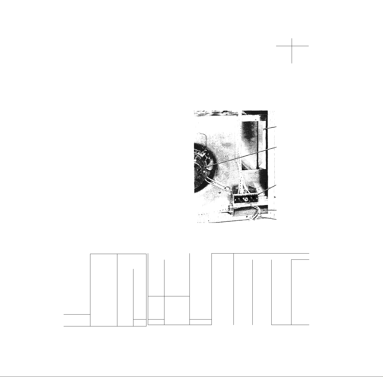
Step 11 — Control Power Wiring (24 v) is brought
through 7/8-in. hole provided in unit. Fig. 1.
Extend leads to unit control wiring terminal board.
Fig. 5. Connect leads to terminal board as directed
in Fig. 7.
HEATER INSTALLATION
AREA
INDOOR FAN MOTOR
CONTROL WIRING
TERMINAL BOARD
WIRING KNOCKOUTS
■AND HOLES
(HIDDEN) SEE FIG t
LINE WIRING
SPLICE BOX
LINE VOLTAGE PIGTAILS
Fig. 5 — Unit Wiring Terminal Location
Table 2 — Unit Electrical Data
OPER
MODEL V/PH
50MQÒ22
50MQ027
S0MQ032
50MQ037
50MQ022
50MQ027
50MQ032
50MQ037
50MQ032
50MQ037
FLA — Full Load Amps
LRA — Locked Rotor Amps
IFM — Indoor Fan Motor
OFM — Outdoor Fan Motor
"Permissible limits of the voltage range at which the units will
operate satisfactorily.
tRequIred when using nonmetallic conduit.
■ —
200/1
230/1 254
200/230/3
200/230/3
VOLTAGE*
Max
220
254 180
254 180
Min
180
207
COMPRESSOR
LRA FLA FLA
75 14.1 2 2
80 16.2 2.2 2.2
99
112
68 12 8
72
88 18 0
100
75 13.0/11.5 3.6/3.1
80
IFM OFM
20.8 3.6 2 2
26.5
14 0
23.0 3.4
15.0/12 8
3.9 2.2 8 35 10
2.0 1 9 12 32
2.0
3 1
3.9/3.4
NO TE S :
1. Fan motors are 200w or 230-v, single-phase.
2. All units equipped with 24-v transformer for external control circuit.
3. Copper wire sizes based on 60 C. Aluminum field wiring may be used
when spiice connected to copper pigtails from unit with factorysupplied wire nuts. Use latest National Electrical Code for aluminum
wire sizing.
BRANCH CIRCUIT
Power Max Gnd Max
FLA
2.2 10 40 10
1.9 10
1 9
1.9 8 45 10
2.2/1.9 10/12 50/42 10/12 35/30
2.2/1.9
Wire Ft
Size
(AWG)
10
10
10/10 45/60 10/10 35/30
W ire
8
35 10
43
47 10
36 10 45
Wire Fuse
Sizet
(AWG)
10 50
12
Amps
35
40
60
30
35
50
Page 5

The 50MQ unit transformer supplies 24-v
power for complete system including accessory
electric heater up to 10 kw. Electric heaters over
10 kw are equipped with 24-v transformer used to
power heater controls.
HH07AT070 THERMOSTAT
HH93AZ076 SUBBASE
GROUND LUG
(IN SPLICE BOX)
Fig. 6 — Line Power Connections
UNIT CONTROL
WIRING TERMINAL BOARD
HH07AT070 THERMOSTAT
HH93AZ074 SUBBASE
50 MO
UNIT CONTROL
WIRING
TERMINAL BOARD
---------
Field Wiring, min 18 AWG
---------
Factory Supplied Wires
HR — Heater Relay
R — Relay
SEQ — Sequencer
Splice
Fig. 7 — Control Circuit Connections
5
Page 6

START-UP
The 50MQ units are equipped with a crankcase
heater. It is recommended that heater be energized
a minimum of 24 hours before starting unit. To
energize heater only, turn the thermostat to “Off’
position and close electrical disconnect to 50MQ
unit.
Heat Anticipator Settings for Room Thermostat
(HH07AT070) — Set anticipator settings for room
thermostat according to Table 3. These settings
may be changed slightly to provide a greater degree
of comfort for a particular installation.
Accessory Outdoor Thermostat provides adjustable
outdoor control of accessory electric heater over
10 kw. This thermostat makes contact when a drop
in outdoor temperature occurs. It energizes a
second stage of electric heat when the outdoor
temperature setting is reached, provided the room
thermostat is on the second stage of heating. Refer
to heat load of building for correct outdoor
thermostat setting. The accessory emergency heat
er relay is manually operated to lock out compres
sor and bypass the outdoor thermostat for electric
heater operation during heat pump shutdown. See
88EH electric heater Installation, Start-Up and
Service Instructions for installation of outdoor
thermostat and emergency heater relay.
To Start Unit — (Ensure crankcase heater has been
energized for 24 hours.) Adjust the thermostat as
follows;
1. Set selector switch at “Off.”
2. Set fan switch as desired (“Fan”) (“Auto.”).
3. Turn on main disconnect switch(es) to unit.
4. Set thermostat dial to the desired temperature.
5. Set selector switch at “Heat” or “Cool.” Check
system refrigerant charge. See Refrigerant
Charging.
50MQ Unit Single-Phase Compressors of the split
capacitor (PSC) type require an equalized system
pressure to start. When supply voltage is within
permissible limits and compressor does not start,
give compressor a temporary capacitance boost.
Use an 88-108 microfarad start capacitor with a
bleed resistor wired across the terminals. Connect
wires with insulated probes to each capacitor
terminal. Touch probes to each side of run
capacitor or to compressor motor terminals R and
S. Start compressor; pull probes away after 3
seconds Discharge start capacitor. (Two or more
bumps may be necessary to start compressor.) Run
compressor for 20 to 30 minutes, then shut off and
allow system pressure to equalize. Try restarting
without boost capacitor. If after 2 attempts (with
out boost capacitor) the compressor does not start,
add an accessory start capacitor relay package.
UNIT CONTROLS
High-Pressure Relief Valve (Safety Control) is
located in compressor. Relief valve opens at a
Table 3 — Thermostat Anticipator Settings
FIRST-STAGE
UNIT
50MQ022, 7.5
027,032,
037
ANTICIPATOR
SETTING
.4
ACCESSORY
ELECTRIC
HTR (Kw)
240 V
208 V
5.0 3.75"
5.6
10 0
15.0 1 1.3
20 0
7 5
15.0
SECOND-STAGE
ANTICIPATOR
SETTINGS i
4 *
56 !
56
.4 ;i
.4 1
pressure differential of approximately 600 psi
between suction (low side) and discharge (high
side) to allow pressure equalization. The valve also
permits pressure equalization when high-side —
low-side pressure differential reaches 90 psig at
shutdown. Compressor can then start unloaded. A
hissing sound during pressure equalization indicates
pressures are equalizing and does not indicate bad
valves.
Internal Current and Temperature Sensitive Over
load (Safety Control) resets automatically when
internal compressor motor temperature drops to a
safe level (overloads may require up to 45 minutes
to reset). When an internal overload is suspected of
being open, check by using an ohmmeter or
continuity tester. If necessary, refer to Carrier
Standard Service Techniques Manual, Chapter 2,
for complete instructions.
Defrost Control, consisting of a defrost timer,
defrost thermostat and defrost relay, interrupts
normal system heating operation if enough frost
forms on outdoor coil to impair unit performance.
Defrost control simultaneously stops outdoor fan,
de-energizes reversing valve solenoid to return
system to cooling cycle (outdoor unit as con
denser, indoor unit as evaporator), and activates
accessory electric heater. Unit can defrost every 90
minutes, but will defrost only if required.
For the heat pump to defrost, 2 conditions are
necessary:
1. Defrost timer contacts must be closed.
2. Refrigerant temperature from outdoor unit
must be cold enough to cause defrost ther
mostat contacts to close. Contacts close at 35
(+0, -6) F.
Every 90 minutes of elapsed running time, the
defrost timer contacts close for 10 seconds. If the
defrost thermostat contacts are closed, the unit
defrosts. The defrost timer limits defrosting period
to 10 minutes. Normally the frost is removed and
the defrost thermostat contacts will open to
terminate defrosting before 10 minutes have
elapsed. Defrost thermostat contacts open at 65
(+0, -6) F. When defrosting is terminated, the
outdoor fan motor and reversing valve solenoid are
energized returning unit to heating cycle.
HEAT PUMP CIRCUITS shown in Fig. 8 are
refrigerant flow diagrams for heating and cooling
cycles.
Page 7

Unit Piping
strainers
Fig. 8 — 50MQ Refrigerant Flow Diagrams
STRAINERS
SERVICE
Table 4 — Service Data
UNIT
R-22 CHG
(Ib-oz)*
Refrig Control
INDOOR FAN
Rpm
Diameter (in.)
Width (in.)
Range Cfm
Motor Hp
OUTDOOR FAN
Cfm
Rpm
Diameter (in.)
Motor Hp
»Factory refrigerant charge.
50MQ022 50MQ027
5.0 ) 5 7 5 7
733-915
1/4
50MQ032
Acc uR a ter ^
Cen tr ifu ga l — Dir ec t D r ive
1050-950-850-800
9
8
9 10
8 8
900-1125 1068-1332
1/4 1/3
Pro pe lle r — Di re ct D r ive
3000
1050
20
1/4
50MQ037
10
8
1230-1540
1/3
REFRIGERANT CHARGING
Unit refrigerant system is factory charged.
When recharging is necessary during heating or
cooling season, weigh in total charge indicated in
Table 4. (Charge must be weighed in during heating
season.) Blow any refrigerant remaining in system
before recharging. Standard 1/4-in. Schrader
Service Connections (Fig. 9) are provided on high
and low sides of refrigerant system for evacuation
and charging.
Dial-a-charge charging cylinder is an accurate
device used to recharge systems by weight. These
cylinders are available at refrigeration supply firms.
A Carrier Chargemaster® charging device
(Carrier Part No. 38GC680004) may be used to
check or adjust refrigerant charge during cooling
season The Chargemaster may also be used as an
alternate method of recharging system.
Chargemaster Operation — Operate unit 10 min
utes before using Chargemaster.
1. Tape Chargemaster feeler bulb to unit suction
line. Insulate bulb. Ensure suction line is clean
for good contact with bulb.
2. Connect refrigerant drum to Chargemaster inlet
port with drum in position for vapor charging.
3. Connect Chargemaster outlet port (loosely) to
unit suction line Schrader valve.
4. Crack valves on refrigerant drum and Charge-
master to purge lines from drum to suction line
Schrader valve. After purging lines, close valve
on Chargemaster only. Tighten Chargemaster®
connection at suction line Schrader valve.
5. Measure outdoor air dry-bulb temperature at
unit.
6. Read evaporator temperature at red needle
position on Chargemaster temperature gage and
suction line temperature at black needle
position
CAUTION: Do not read evaporator tem
perature with Chargemaster valve open.
7. Enter 50MQ Chargemaster Charging Chart,
Table 5, at outdoor air temperature (step 5)
and evaporator temperature (step 6). Find the
suction line temperature required for correct
system charge. If actual suction line tem
perature (step 6) is higher than table value, the
system is undercharged. If suction line tem
perature is lower than table value, the system is
overcharged.
Example- At outdoor air temperature of 85 F
and evaporator temperature of 40 F, the system
will be correctly charged at 48 F (±2 F) suctior
line temperature.
Page 8

8. Add charge by slowly opening Chargemaster®
valve. If necessary, reduce charge by bleeding at
liquid line Schrader valve. Check outdoor air
and evaporator temperature during procedure.
If they change, refer back to Chargemaster
Charging Chart for new value.
Correct use of Chargemaster ensures an opti
mum refrigerant charge will be in system when
conditions and system components are normal.
However, the Chargemaster does not solve or fix
system abnormalities It indicates correct charge
for condition of system. It will not make correc
tions for dirty filters, slow fans, excessively long or
short suction lines, or other abnormal conditions.
This charging device ensures that a correct relation
ship exists between outdoor temperature, evap
orator temperature, and suction line temperature
on a specific system.
Table 5 — 50MQ Chargemaster® Charging Chart
6. Remove compressor hold-down bolts. Lift com
pressor out.
CAUTION: Aluminum tubing is used in
50MQ unit coils. Do not overiieat or place
excessive strain on tubing or damage may
result.
Table 6 — Compressor Data
MODEL
50MQ022
50MQ027
50MQ032
50MQ037
50MQ022
50MQ027
50MQ032
50MQ037
5ÒMQ032
50MQ037
V/PH
200/1
230/1
200-230/3
PRODUCTION
COMPRESSOR
MB2423CB
MB2723CB
MB3423CB
MB4023CB
M52423CB
MD2723CB
MC3423CB
MC4023CB
MF3423CB ~
MF4023CB
OIL
RECHARGE (oz)
44
OUTDOOR
TEMP
(F)
60
65 40
70
75 37 46
80
85 42 -48
90 44
95 40 45 5 C
100 44
105
‘Saturated temperature which is the equivalent temperature of
pressure taken at the heat pump suction Schrader fitting.
EVAPORATOR TEMPERATURE (F)*
38 2ÏÔ
Te
Ó6
64
55
55
42 44
mperatu
62
54 61
49
42
28
30
32
Suet on Line
50
65
48
36
34
36,
72
56 Ó6
56
46
40
47
46 48 50|
res
60
55
55
50
60
54 59
50
54 58
COMPRESSOR REMOVAL
See Table 6 for compressor information and
Fig 10 for component location.
1. Shut off power to unit. Vent refrigerant to
atmosphere or use refrigerant removal methods
shown in Carrier Standard Service Techniques
Manual, Chapter 1.
2. Remove unit corner access panel. Fig. 1.
3. Remove core from suction and discharge line
Schrader valves.
4. Disconnect compressor wiring at compressor
terminal box. Carefully unsweat suction and
discharge (hot gas) lines at compressor. Do not
stress or move compressor discharge line or it
may break at condenser connection.
CAUTION: Excessive movement of copper
lines at compresksor may cause a break where
lines connect to evaporator or condenser.
5. Remove crankcase heater from compressor
base.
Filter-Drier — Install a filter-drier in compressor
suction line when refrigerant system is opened for
service as described under Compressor Removal.
Fig. 9 shows suggested position of drier. Check
filter-drier pressure drop at drier service port and
unit suction line Schrader fitting. Ensure pressure
drop does not exceed 2 psi.
CONTROL BOX
4-WAY VaL^:
DISCHARGE LINcl
(HIGH SIDE)IS2!r
SCHRADER FITTING
$
FILTER-DRIER
SERVICE
FILTER-DRIER
(FIELD SUPPLIED)
SUCTION LINE
accumulator;
SUCTION LINE
(LOW SIDE)"
SCHRADER FITTING
COMPRESSO!
COMPRESSOR HOLD
DOWN BOLTS (4)
COMPRESSOR ’
TERMINAL BOX
Fig. 9 — Compressor Removal
MAINTENANCE
Lubrication
COMPRESSOR contains factory oil charge. Re
place oil when lost. See Table 6 for oil recharge. If
necessary, refer to Carrier Standard Service Tech
niques Manual, Chapter 1, pg 1-21, for oil re
charging procedure. Use Carrier PP33-1, Texaco
Capella B or Suniso 3G oil.
Page 9

FAN MOTOR BEARINGS are prelubricated for 3
years heavy duty or 5 years normal duty. When
lubrication is necessary, send motor to authorized
motor repair shop.
Evaporator (Indoor Coil)
OUTDOOR FAN AND MOTOR REMOVAL Remove screws holding outdoor coil fan grille in
place. Disconnect fan motor leads from controllers
and capacitor. Lift complete fan, motor and orifice
assembly (Fig. 10) out of unit. After replacing fan
motor assembly, reconnect fan motor leads.
CAUTION: Before performing recommended ;
maintenance, be sure main power switch to unit
is turned off.
COIL ” Lift or remove unit top cover for access to
indoor coil. See Fig. 10. Inspect coil periodically.
Clean as described under Condenser (Outdoor Coil)
below.
Condensate Drain
with bottle brush,
Clean condensate drain trap
then flush condensate pan
beneath evaporator coil with clean water. Ensure
water flows freely thru condensate drain.
INDOOR FAN WHEEL should be centered in fan
housing. To adjust fan, remove fan motor orifice
assembly as described below. Loosen setscrew
holding fan to motor shaft. Adjust fan and
retighten setscrew.
Indoor Fan Removal — See Fig. 10. Disconnect fan
motor wiring. Remove sheet metal screws (6)
holding fan orifice in place. Remove fan motor
bracket mounting screws (3). Slide out complete
fan, motor and orifice assembly.
Cleaning Indoor Fan Wheel — Remove caked-on
dirt from fan wheel and housing with brush;
remove grease with mild solvent. When replacing
blower assembly, ensure fan wheel is centered in
housing.
Condenser (Outdoor Coil)
COIL “ Lift or remove top cover for access to
outdoor coil. See Fig. 10. Inspect coil periodically.
Clean coil with water at the beginning of every
cooling season or more often if required. Use
ordinary garden hose at a pressure high enough to
clean efficiently. For best results, spray coil fins
from inside-to-outside the unit or top to bottom
between rows of tubing. Flush dirt from base pan
by spraying water thru top of unit. Avoid splashing
mud on coil or water on the fan motor.
OUTDOOR FAN POSITION - Required fan posi
tion is shown in Fig. 11. Adjust fan by loosening
setscrews and moving blades up or'down.
UNIT TOP CCVER
OUTDOOR FAN-ORIFICE
FAN MOTOR ASSEMBLY
NDOOR COIL
OUTDOOR COIL
4-WAY VALVE
CONTROL BOX
ACCUMULATOR
LINE WIRING
AIR FLOW
INDOOR FANORIFICE MOTOR
SPLICE BOX
Fig. 10 — Component Location
FANBLAOe
/
TOP OF
SLADE
L
------'------'------------
SETscf?ew
MOTOR
• -JiVMXl '
2,00 iri \
№
Fig. 11 — Outdoor Fan Position
Return Air Filter (Field Supplied) — Replace
throwaway filter twice a year. Clean permanent-
type filter a minimum of twice yearly. Flush
permanent filter with hot water, steam or soak in
mild solution of soap or detergent and water.
Allow filters to dry and replace. Refer to filter
manufacturer’s instructions, as required, for other
types of filters.
Page 10

TROUBLESHOOTING CHART - COOLING CYCLE
Page 11

TROUBLESHOOTING CHART - HEATING CYCLE
NO HEATING OR
INSUFFICIENT HEATING
CONTACTOR
OPEN
OPENING IN
POWER CIRCUIT
DEFECTIVE LOW
VOLTAGE
TRANSFORMER
REMOTE CONTROL
CENTER DEFECTIVE
CONTROL RELAY
COIL OR CONTACTS
DEFECTIVE
REVERSING VALVE
RELAY DEFECTIVE
CONTACTOR COIL
OPEN OR SHORTED
KLIXON OR OVER
LOAD DEFECTIVE
COMPRESSOR
WILL NOT RUN
CONTACTOR
CLOSED
COMPRESSOR
POWER SUPPLY
OPEN
LOOSE LEADS
AT COMPRESSOR
FAULTY START
CAPACITOR OR RELAY
SINGLE PHASE ONLY
COMPRESSOR
STUCK
INTERNAL
OVERLOAD
DIRTY FILTERS
OR INDOOR COIL
INDOOR FANS
CYCLING ON
OVERLOAD
DEFECTIVE FAN
MOTOR CAPACITOR
LOOSE LEADS AT
FAN MOTOR
FAN MOTOR
BURNED OUT
DAMAGED
REVERSING VALVE
RESTRICTION IN
DISCHARGE LINE
1
COMPRESSOR RUNS
BUT CYCLES ON
LOW LINE VOLTAGE
OR UNBALANCED
3-PHASE LINE
DEFECTIVE RUN
CAPACITOR
(SINGLE PHASE)
COMPRESSOR
BEARINGS
HIGH LOAD
CONDITION
OVERCHARGE OR
NONCONDENSABLES
REVERSING VALVE
JAMMED IN MID
POSITION
1
1 ■■ "
LOW SUCTION
LOW HEAD
OUTDOOR FAN
STOPPED
LOOSE LEADS AT
OUTDOOR FAN
MOTOR
INTERNAL FAN
MOTOR KLIXON
OPEN
FAN MOTOR
BURNED OUT
DEFROST RELAY
N.C. CONTACTS
OPEN
—1 p
COMPRESSOR RUNS -
INSUFFICIENT HEATING
OUTDOOR fan
RUNNING
RESTRICTED
LIQUID LINE
ACCU RATER '
RESTRICTED OR
ICE CLOGGED
UNDERCHARGED
OUTDOOR COIL
^ DIRTY
OUTDOOR COIL
HEAVILY FROSTED
DEFECTIVE DEFROST
THERMOSTAT
1
STRIP HEATERS
NOT OPERATING
OUTDOOR
THERMOSTAT
DEFECTIVE
ODT SETTING
TOO LOW
CAP TUBE PINCHED
OR BULB NOT
SENSING TRUE ODT
STRIP HEATER RELAY
OR CONTACTOR
DEFECTIVE
OPENING IN POWER
CIRCUIT TO HEATER
ELEMENTS
BLOWN FUSE LINK
BROKEN HEATER
ELEMENT
OVERCHARGE OR
NONCONDENSABLES
IN SYSTEM
DEFROST THERMOSTAT
IN POOR PHYSICAL
CONTACT WITH LINE
DEFECTIVE DEFROST
RELAY OR DEFROST
TIMER
REVERSING VALVE
STUCK
BAD ELECTRICAL CONNECTiON ANYWHERE IN
DEFROST CIRCUIT
4 INTERNAL PRESSURE
RELIEF OPEN
OPEN (KLIXON)
OVER-TEMPERATURE
THERMOSTAT
DEFECTIVE ROOM
THERMOSTAT
(2ND STAGE)
Page 12

For replacement items use Carrier Specified Parts.
Manufacturer reserves the right to discontinue, or change at any time, specifications or designs without notice and without incurring obligations.
Tab 12
Form50MQ-1SI New
Printed in U.S.A.
12-74
Codes D and MS Catalog No 535-070
 Loading...