

Page 1
Carrier
ingle-Packagé Cooling Units
(Mobile Home Unit)
INTRODUCTION
The 50MH unit is a complete cooling system,
with provision for addition of accessory electric
heaters. Units are air cooled, designed for outdoor
installation and may be connected into existing
duct system Required connections include air
ducts, condensate drain, line and control power
wiring, A field-supplied filter box must be installed
for return air.
TRANSPORTATION DAMAGE
File claim with shipping company if shipment is
damaged or incomplete. Move unit to installation
site in upright position.
PRELIMINARY SURVEY
Consult local building codes for special installa
tion requirements.
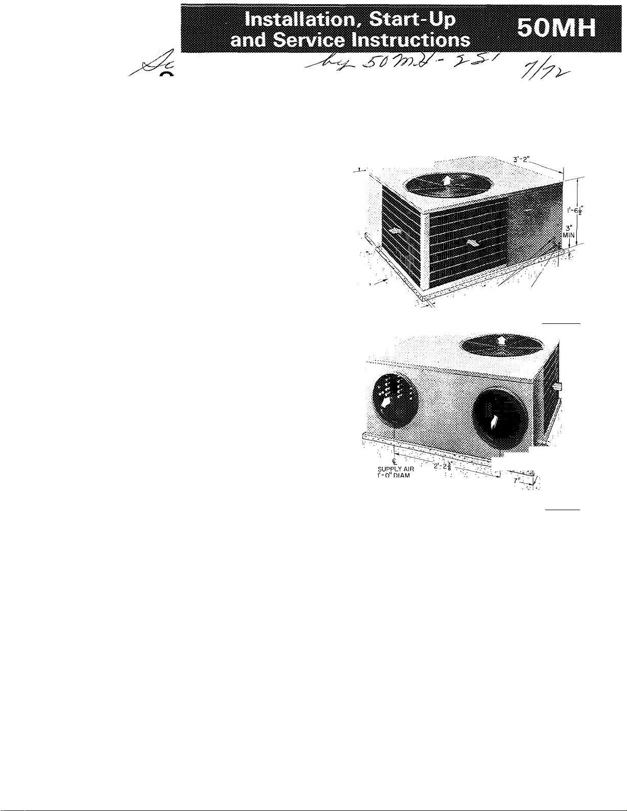
When installing unit, allow sufficient space for
condenser air-flow clearance, wiring, and servicing
unit (see Fig. 1). Position unit so water from roof
will not pour directly on top of unit.
Mounting Pad (Fig. 1) — Install unit on a solid,
level-poured concrete pad or equivalent. Construct
pad so top is a minimum of 3 in. above ground
level. Pad must not be more than one inch longer
or wider than unit. Extend a 24-in. gravel apron
completely around pad. Insert a sheet of tar-base
construction felt paper between unit and pad.
DUCTWORK
Design duct system to have a friction loss of
between .25 in. wg and .70 in. wg for proper unit
operation. Insulated flexible ductwork (1-ft inside
diameter) of weatherproof type is recommended.
Do not reduce duct inside diameter below 1 ft.
Combined length of supply and return ducts
should not exceed 20 ft with a minimum supply
duct length of 6 ft and a minimum return duct
length of 3 ft. Do not operate unit longer than 5
minutes without ductwork. If necessary, refer to
Carrier System Design Manual, Part 2, for air duct
design.
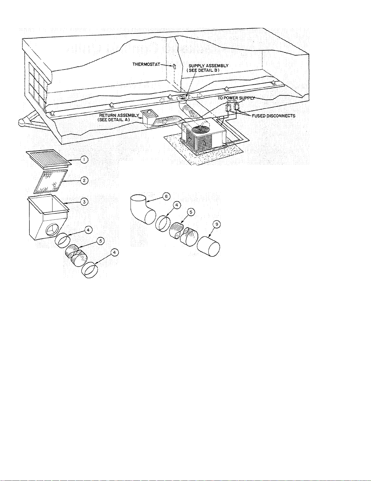
Flanges are provided on unit for attaching
ductwork. See Fig. 1 for connection sizes and Fig.
2 for typical duct installation.
Supply Air Connection — Connect flexible duct to
unit supply air connection. When unit is equipped
with electric heaters, insert a sheet metal sleeve
inside of flexible duct. Sleeve must extend 24 in.
from electric heater element. At approximate
4'-0" OVERHEAD
; AIR SPACE REQUIRED
I DIAM LOW
2-0
GRAVEL APRON
AROUND PAD :
OPERATING WT:
50MH003-275 LBS
50MH004-295 LBS
M POWER ® DIAM
A' MAX cnppi Y KNOCKOUT
(4 SIDES) KNOCKOUTS
li DIAM |3 nv,...
VOLTAGE CONN
FRONT VIEW
■'Mli
t
-
---
11^ EVAPORATOR AIR FLOW
^CONDENSER AIR FLOW
Fig. 1 — Dimensions and Connections
■ i"
<L ^
RETURN AIR
'-0" DIAM
ID
CONDENSATE
DRAIN
REAR VIEW
center of trailer, connect flexible duct to main
supply duct with a 90-degree sheet metal elbow.
Install turning vanes in main supply duct directly
above elbow connection using standard sheet metal
practices.
Return Air Connection — Purchase or field fabri
cate a filter box. Suggested minimum filter box
dimensions are shown in Fig. 3 (see page 3). At
approximate center of trailer, cut a return air
opening in floor. Locate opening where it will not
be obstructed by furniture. Size opening to accept
filter box. Cut hole in carpet or floor covering
same size as filter box floor opening. Ensure
electrical wiring or main structural supports are not
accidentally cut. Insert filter box thru floor open
ing. Weatherseal floor connection in accordance
with good construction practice. Insert filters in
filter box, and cover with return air grille.
® Carrier Corporation 1971
Form 50MH-1SI
Page 2
DETAIL A
(RETURN ASSEMBLY)
DETAIL B
(SUPPLY ASSEMBLY)
Fig. 2 — Typical Installation
(7) RETURN A5R REGISTER
( z ) l4*x25”;il“nETER(PERMANEN7
^ TYPE)
iT) RETURN AiR PLENUM
COLLAR
0
FLEXIBLE DUCT
:0! BAFFLE
(T) TAP*IN COLLAR
(e) INSULATED ELBOW
LINER
------
CONTROL WIRING
——POWER WIRING
^ CONDENSER AIR FLOW
evaporator air flow
Connect flexible duct to filter box. Extend
duct from filter box to unit return air connection.
If possible, insert a total of a 90-degree bend in
return air duct for sound dampening. Connect duct
to unit return air connection.
When existing furnace is kept in system:
During heating season, insert a sheet metal
panel beneath return air grille and over filter to
prevent air movement thru cooling unit.
When furnace is removed from system, blank
off original furnace floor connection.
CONDENSATE DRAIN
A condensate trap is factory supplied and taped
to unit suction line for shipment. Connect trap to
unit condensate drain fitting with clamp provided.
See Fig. 4 and 5.
Applying Clamp
1. Pull ends apart.
2. Wrap around condensate trap with toothed end
beneath. Prelatch by compressing until last
ratchet teeth catch behind small tabs.
3. Grip adjacent bridges with pliers and compress
to tight position.
4. To remove, lift the locking tongue with
screwdriver.
ELECTRIC RESISTANCE HEATER
Remove fan section access panel and sheet
metal plate covering heater installation area (be
tween evaporator fan discharge and supply air
connection). See Fig. 6. Discard sheet metal plate
and insert heater into opening provided. Insert
heater support bar thru hole in side of fan
discharge duct. Fasten heater in place at top and
bottom with two sheet metal screws. See Wiring
section for power connection details.
Page 3
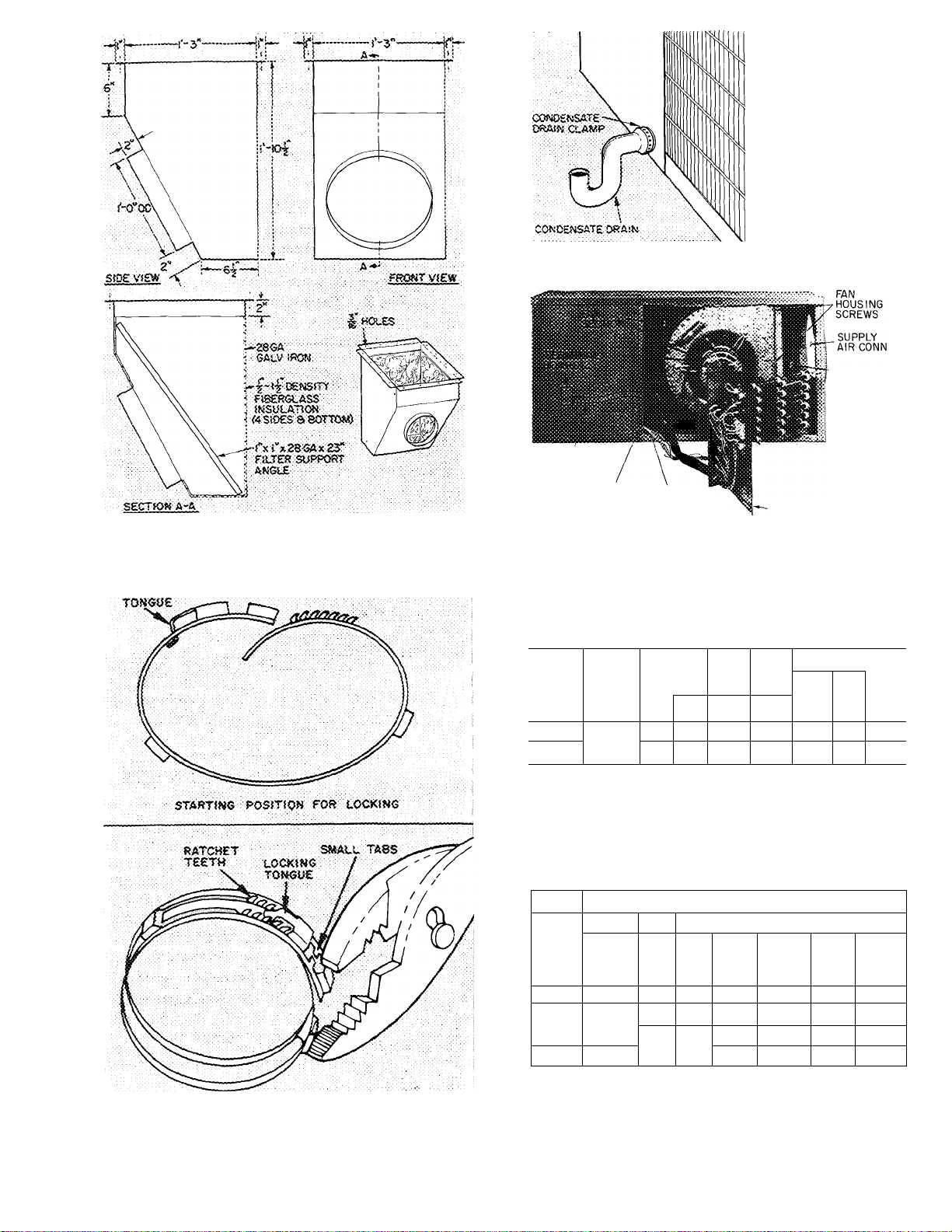
Fig. 3 — Minimum Dimensions Return Air
Filter Box
fRl
mi
RI
Fig. 5 — Condensate Drain Connection
LINE POWER
LEADS FROM
HEATER
CONTROL
WIRING
RECEPTACLE
Fig. 6 — Electric Resistance Heater Installation
CONTROL
LEADS
FROM HEATER
ELECTRIC HEATER
ASSEMBLY
HEATER
INSTALLATION
OPENING
i.0Ci(fN6
ELECTRICAL DATA AND WIRING
Table 1 — Unit Electrical Data
EVAP
COMPR
PH
LRA FLA FLA FLA
86.0 19.5 3.4 1 1 10 30
20 0
93 0
50MH
003
004
VOLTS/
230/1
MODEL
LRA — Locked Rotor Amps
FLA — Full Load Amps
NOTE:
Motors and controls will operate satisfactorily 10% above and 10%
below unit voltage. Control circuit voltage is 24 volts on all units.
COND
FAN
FAN
3 4 1 1 10 30 30
BRANCH CKT
Wire
Max
Size
Wire
(AWG)
Fuse
Ft
Amps
30
Table 2 — Electric Resistance Heater Data
ELECTRIC HEATER
UNIT
50MH
003
&
004
Volts/
Ph
240/1
KW
No.
1
5
1 41.7 6 30
10
15 2
Branch Circuit
FLA
(ea)
Wire
Size
(AWG)
20.8 10
20 8
41 7 6
10
Max
Ft
Wire
30
30 30
30 50
Fuse
Amps
30
50
CLA«P IN LOCKIXS POSJTiO«
Fig. 4 — Condensate Drain Clamp
Wiring — Field wiring must comply with local and
national codes. Install a branch circuit fused
disconnect of adequate size to handle unit starting
current. Provide a separate fused disconnect for
Page 4

each electric resistance heater. Voltage to unit
during operation must be within ± 10% of voltage
range indicated on nameplate.
THERMOSTAT’
&-
TERMINAL
BOARD 3
Failure due to operation of unit on improper
line voltage constitutes abuse ana is not covered
by Carrier Warranty.
LINE POWER — Bring line power leads from fused
disconnect thru hole provided (Fig. 1) into high
voltage section of control box. Connect line power
leads to Terminals 1 and 2 on Terminal Board 1.
See label diagram and Fig. 7. Aluminum field
wiring may be used when splice connected to
copper pigtails from unit with approved copper to
aluminum splice connectors.
Accessory Electric Fleater(s) — Connect line power
leads from fused disconnect(s) to Terminal Board 2
as shown in Fig. 7. Extend power leads (supplied
with electric heater) from heater thru fan section
and thru hole provided into high voltage section of
control box. Connect leads to Terminal Board 2
(Fig. 6 and 7).
№
&-
0
------------------------------------
Connect Terminal G to Terminal 2 for operation with electric
heater or Terminal 3 for operation without electric heater
_____
Field Wiring
*HH01 YA092 thermostat with HH93YZ096 subbase
Fig. 8 — Thermostat Connections
-a
-Q
a
TO
HEATER
FD
—
TO (-
HEATER <
FD 1-
FD — Fused Disconnect
______
Field Wiring
______
Factory-Supplied Wire (Field Connected)
<Q) Unmarked Terminals
”0—[aF
—
-0—0-
RED
BLK
YEL
BLU
(2
TO
)
10 Kw
HEATER
1 TO
> 5KW
1 HEATER
Fig. 7 — Line Power Connections
Evaporator Fan Motor is factory wired for high
speed operation as shown in Fig. 9. If medium or
low speed operation is desired, remove black motor
lead from Contactor Terminal 23 and replace with
blue motor lead for medium speed or red motor
lead for low speed. Tape unused leads separately.
THERMOSTAT LEADS (24 v) are brought thru
hole provided (Eig. 1) into low voltage section of
control box. Connect leads to Terminal Board 3 as
shown in Eig. 8 and 9.
Accessory Electric Heaters — Extend control leads
with plug (supplied with heater) thru fan section
and insert plug into receptacle located on side
panel of control box. See Fig. 6 and 9.
— Thermostat, Cooling
— Contactor
c
— Compressor TDR
Comp
— Fan Capacitor (1FM)
FC
FR — Fan Relay Tran — Transformer
— Indoor Fan Motor
IFM
— Low-Press. Switch
LPS
OFM — Outdoor Fan Motor
R — Relay
RC — Run Capacitor (Dual)
SC
— Start Capacitor
SFR — Safety Fan Relay
— Start Relay
SR
— Terminal Board
TB
NOTES
1. To be wired in accordance with NEC and local codes
2 Low-pressure cutout setting 27 0 ± 4 psig.
3. Terminations in junction box suitable for NEC Class 2 control
circuit, at 24 volts
4 Motor provided with inherent thermal protector,
5. Terminal G connects to terminal no 2 for operation with electric
heater.Terminal G connects to terminal no. 3 for operation with
out electric heater
TC
— Time-Delay Relay
TH — Thermostat, Heating
Field Power Wiring
—
___
. Field Control Wiring
NEC Class 2, 24 v.
Marked Connections
o
Unmarked Connections
O
Terminal Board Connections
□
Fig. 9 — Typical System Wiring Diagram
Page 5

START-UP
Adjust remote control center as follows:
1. Set selector switch at “Off.”
2. Fan switch at “Auto.” or “Fan.”
3. Turn on main disconnect switch(es) to unit.
4. Set thermostat dial to the desired temperature.
5. Selector switch at “Heat” or “Cool.”
Electric Resistance Heater Operation — When
thermostat calls for heating, evaporator fan and
heater no. 1 are energized immediately. Remaining
heaters are energized in 30 second intervals. When
thermostat is satisfied, the cycle reverses and
heaters are de-energized in 30-second intervals.
Evaporator fan motor shuts off with last heater.
SERVICE
Table 3 — Service Data
Manual, Chapter 1, pg 1-21, for oil recharging
procedure. Use Carrier PP33-1, Texaco Capella B
or Suniso 3G oil.
Fan Motor Bearings are prelubricated for three
years heavy duty or five years normal duty. When
lubrication is necessary, send motor to authorized
motor repair shop.
CONDENSER
Coil — Lift or remove unit top cover for access to
condenser coil. Inspect coil periodically. Clean
with brush, vacuum cleaner, low-pressure water,
steam or air.
Fan Position — Required fan position is shown in
Fig. 10. Adjust fan by loosening setscrews and
moving blades up or down.
#
UNIT 50MH003
R-22 CHG (Ib-oz)*
Refrig Control
COMPRESSOR
Type Start CSR
Oil Recharge (oz) 45 50
EVAP FAN
Rpm
Diam (in.) 10
Width (in.)
Nom Cfm
Norn Motor Hp
COND FAN
Rpm
Diam (in.) 18
Norn Cfm
Norn Motor Hp
CSR — Capacitor Start
* Factory refrigerant charge
3-0 3-11
TXV
38GC401404 51YA400524
Centrifugal —
1075 - 950 - 850
8
1125
Propel 1er —
1050
2400
%
50MH004
TXV
CSR
Direct Drive
10
8
1350
Di rect Drive
1050
18
2400
ke
REFRIGERANT CHARGING
Refrigerant System is factory charged. When
recharging is necessary, weigh in total charge
indicated in Table 3. Blow any refrigerant
remaining in system before recharging. Standard
1/4-in. Schraeder service connections provided on
high and low sides of refrigerant system for
evacuation and charging.
LUBRICATION
Compressor contains factory oil charge. Replace oil
when lost. See Table 3 for oil charge. If necessary,
refer to Carrier Standard Service Techniques
EVAPORATOR
Coil — Lift or remove unit top cover for access to
evaporator coil. Inspect coil periodically. Clean
with brush, vacuum cleaner or low-pressure air.
CONDENSATE DRAIN — Clean condensate drain
trap with bottle brush, then flush condensate pan
beneath evaporator coil with clean water. Ensure
water flows freely thru condensate drain.
Evaporator Fan Wheel should be centered in fan
housing. To adjust, loosen setscrews holding fan to
rhotor shaft. Adjust fan and retighten setscrews.
EVAPORATOR PAN REMOVAL - Disconnect
fan motor wiring. Remove two fan housing sheet
metal screws shown in Pig. 6 and slide out
complete fan and motor assembly.
RETURN AIR FILTER
Clean filter a minimum of twice yearly. Flush
permanent-type filter with hot water, steam or
soak in mild solution of soap or detergent and
water. Allow filters to dry and replace. Refer to
filter manufacturer’s instructions, as required, for
other types of filters.
«
Page 6

TROUBLESHOOTING CHART
Page 7

I
Û
lU
L.
CO
O
_J
O
UJ
a.
<
h-
cc
o
LU
« a
y S
Û- CO
< X
ifi
Q
Z
< z
LÜ LU
■y Û.
^ o
_J
w
X
hÜ
z
o
_J
<
u
<
CÛ
Q
_J
o
z
o
WARRANTY - EXTENDED PROTECTION PLAN
GENERAL WARRANTY STATEMENT - We warrant all
I
Carrier products to be free from defects in material and
workmanship under normal use and service Our obligation
shall be limited to repairing or supplying a replacement for
the defective part, assembly or portion thereof, which our
inspection shall show to be defective, F.O.B. Carrier factory.
PERIOD OF COVERAGE
First Year Warranty — The above warranty applies for one
year from date of original installation to all parts and
components in the Carrier product identified below
excepting refrigerant, air filters and filter-driers which are not
included in any part of this warranty.
Motor-Compressor Protection Plan — The above warranty
applies for five years from date of original installation to the
Hermetic Motor-Compressor only in the product identified
below Cartier will allow transportation for the Hermetic
Motor-Compressor between the factory and its authorized
distributor.
GENERAL CONDITIONS — This warranty does not cover
the cost of labor for any adjustments or service calls, nor
does it include the cost of labor for replacing defective parts
or components.
This warranty does not apply if the Carrier product or
any part thereof has been subjected to misuse, abuse, neglect,
accident oi alteration.
This warranty applies only to Carrier products installed
within the boundaries of the Continental United States,
Canada and Hawaii, and only applies- to parts supplied oi
designated by Carrier.
This warranty is in lieu of all other warranties expressed
or implied, and in no event shall Carrier be liable for any
special, indirect or consequential damages
IMPORTANT — Obligations of Purchaser (not included in
this warranty)
1. Failure to start due to voltage conditions, blown fuses or
other damage due to inadequacy or interruption of
electrical service.
2. Filter replacement or cleaning of evaporator coil, con
denser coil or heat exchanger.
3. Damage due to freezing of condensing water, inadequate
or interrupted water supply, use of corrosive water or
rearrangement of plumbing system.
4. Failure resulting from overfiring, use of incorrect fuel,
and improper burner or control adjustments.
5. Damage caused by accident, misapplication, abuse,
alteration, tampering or servicing by other than an
authorized agency.
6. Damage resulting from use of equipment in corrosive
atmosphere.
7. Damage due to lack of proper maintenance.
Carrier products are the result of years of research in
development laboratories. The most modern precision pro
duction methods, together with every precaution through
inspection and test, combine to insure long life and
economical service. The user of this product should assist in
maintaining this maximum of long life and economical
service by following the instructions contained in the
Instruction Packet included with the product
I
Service or other labor charges not included in this warranty may be covered by a service agreement through the seller at time of purchase.
Such agreement or contract shall be separate and apart from this factory equipment warranty.
CARRIER AIR CONDITIONING COMPANY • SYRACUSE, NEW YORK
Name of Owner ^ . . ....
Address of Installation
Unit Model No. . . . .......
Unit Serial No.
______
Date of I nstallation
Installed by
......
_____
....
............
____
............ .
...
..............
__________
........
............
.......... ........
. ________ ....
.
................. .
... ...
...............
____ _ . _________
___
........
___
.....
_
________
........
..
.
_
_________
_
_______ _
-
_____
_
-
Fill out warranty record and return to Carrier Air Conditioning Company,
Syracuse, N.Y. within 15 days after installation in order for this warranty to
be effective.
I
Page 8

FOLD BACK ALONG THIS LINE AND STAPLE, GLUE, OR TAPE CLOSED -
OPEN ON THIS END
cr Q
a: P
D
Q_
CD
*D
c o
> JD
ID
CQ
o
CD
D
Q-
O
O)
D
O
D
Q_
O
O
O
O
13
Q.
o'
O
O
CD
O
13
<
Q.
O
c
o
o
d
D
OD
X
D
03
C/3
o
03
d
W
03
Q-
X
—
Q_
D
□
□
o
I
o
CO
o
H
o
c
z
H
-<
,
c
73
00
m
H
m
o
H
S
m
30
z
>
CO
o
o
c
z
-<
D
H
m
73
> H
m
1"
m
m
H
73
2
>
m l~
,
□
□
□
in
o
CD <
□
o
CD
■D
C
ID
□
X
o
X
Qo
□
03
c
CD
O
X
o
3 .
CD 1
□
M
03
CO
d
H
_
>
H
X
m
O
3
CD ; 1
!
□
>
"O
CO
o
H
<
!
g
H
H
>
-<
H
m
1
1
1
'
CO
D
m
>
73
m
>
1“
z
z
V)
H
p
>
l-
m
O
BUSINESS REPLY ENVELOPE
FIRST CLASS PERMIT NO. 1005, SEC. 34.9 P.L. & R., SYRACUSE, N. Y.
CARRIER AIR CONDITIONING COMPANY
—!
o
D"
>
CD
O
o
>
z
CD
CT
C/3
H
CD
Q.
-<
33
<
m
CD
D
o
Q_
O
C
33
CD
D
j
1
-D
> .
H !
Z '
p
CARRIER PARKWAY
SYRACUSE, NEW YORK 13201
SERVICE ENG. DEPT. TR-20
FOLD LINE
□
O i
j ■
CD
□
o
CT
I
o
INSTRUCTIONS
N
N
•V
If any equipment deficiencies are found at the time of instal
lation, fill out the reverse side of this form giving a com
plete, explicit description. Use sketch if necessary. Make
out and mail a report every time a deficiency is found.
Page 9

For replacement items use Carrier specified parts.
Manufacturer reserves the right to change any product specifications without notice.
CARRIER AIR CONDITIONING COMPANY • SYRACUSE, NEW YORK
Tab 18 Form50MH-1SI New Printed in U.S A. 3-71 Codes D and MS Catalog No. 535—008
 Loading...