

Page 1
yi..
тм
Hot Water/Glycol Heating 160,000 to'800,000 Btuh
Eiectric Cooling 180,000 to 360,000 Btuh
Electric Heating 180,000 to 540,000 Btuh
Gas Heating 480,000 to 720,000 Btuh
„ „ ,/йГ(1\ (eroRJlgjy/ KSnVV^lloro); ((U(eS3l!S|lil
Й1 d bib ul px eir i PJ ilo io ilt si oo V, йо хо )
0 ® Commercial buildings
:© Carrier Corporation 1982
Form 48MA/50ME-3P
Page 2
No hot decks. . .no cold decks. . . no zoning dampers. . .no energy waste!
It’s what you don’t get with Carrier’s
Zone-Mizer Modular Multizone unit
that sets it apart from all the others.
You don’t get hot decks or cold decks
because the Carrier design gives each
zone module its own cooling coil and
heating section. Each zone module
operates independently. One unit can
heat, cool, dehumidify, reheat, and
ventilate up to 12 different zones simul
taneously. All this means real energy
savings. . .there’s no wasteful duplica
tion of effort as in hot deck/cold deck
units. For still more energy savings,
Zone-Mizer provides up to 3 steps of
electric heat or gas heat with an inter
mittent pilot ignition in every zone.
Something else you don’t get. . .
zoning dampers. Since the Carrier de
sign doesn’t have hot and cold decks, it
doesn’t need zoning dampers. By elimi
nating them from the picture, you
eliminate the adjustments, service, and
operating problems that go along with
zoning dampers.
Five sizes, offering capacities to 37
tons, provide equipment flexibility and
economy. One large unit may serve
where 2 units were required before; or
units of different sizes may be mix/
matched to deliver the heating/cooling
capacity required in a specific applica
tion. And the choice of gas, elecfric or
hot water/glycol coils allows you to
select a unit that can deliver maximurn
operating economy and convenience by
taking advantage of an already available
heating plant or favorable area fuel
rates.
1 Etched solid copper circuit
panels have interchangeable plug-in
relays to minimize parts stocking Cir
cuit breakers that may be used as dis
connect switches, terminal boards to
simplify installation of accessories, a
control circuit shutoff switch and 24volt controls are all standard.
Motorized outdoor air inlet
damper — A simple rheostat adjust
ment on the unit (or on the optional re
mote control panel) sets the damper to
control the amount of outdoor air
admitted.
5 Dependable cooling — Each ser
viceable hermetic compressor system
has cylinder unloaders for capacity con
trol and electric power savings. Crank
case heaters, accumulators, filter driers
and low-ambient starting controls are
also standard.
Time Guard® electrical circuit pre
vents rapid cycling of the compressor if
occupant tampers with the thermostat.
Compressor cannot short-cycle on a
safety device, such as the low-pressure
switch, should someone forget to clean
the air filters.
Capacity control permits a wide oper
ating range. During light loads the com
pressor automatically unloads to re
duce operating costs and maintain
steady compressor operation. When
the load drops below the minimum
unloader stage, the hot gas bypass con
trol provides continuous cooling
operation.
Built-in safety controls prevent
damage to unit components. Included
are high- and low-pressure switches,
overtemperature limit switches and
overload protection for all motors.
When specifying a multizone unit,
choose the one that makes a point of
doing something about installation
problems. . .the Carrier Zone-Mizer
Modular Multizone. It’s a sturdy, onepiece unit — factory-wired, piped, and
charged. It arrives ready to be set in
place on the specially designed roof
curb. Make the power and control con
nections and that’s it. Initial adjust
ments are trouble free — you won’t
even need a factory engineer at start
up. The total package carries the UL
label or is design certified by AGA.
DG
3 Fused 115-volt convenience out
let in the control box provides power at
the unit for work lights and small power
tools.
4 Motormaster® solid-state con
denser fan speed control permits
year-round operation of refrigeration
system down to -20 F ambient.
6 Polyurethane foam sandwich
access panels are of Weather Armor
galvanneal steel. Their thermal resis
tance prevents sweating at outdoor
conditions up to 77 F dew point And
they are strong enough to support a
250-pound man.
Page 3
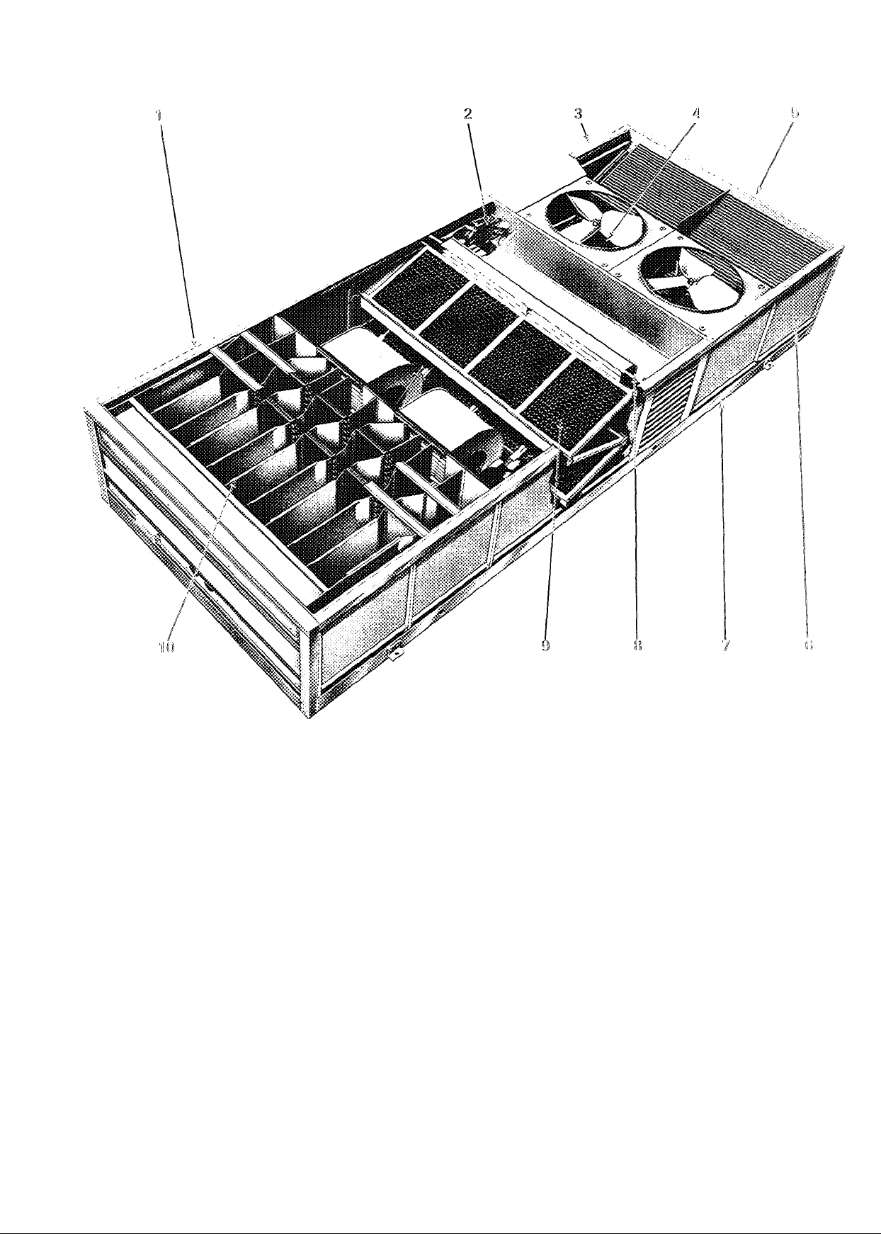
/ Rugged extruded aluminum
frames and protective grilles provide
strength and good looks. Unit will not
sag during rigging.
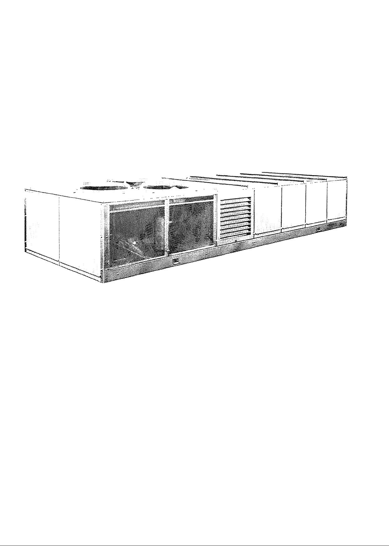
Low silhouette — The cabinet has no
vents or hoods to break up the clean
appearance. The curb-mounted unit
seldom requires a parapet to hide it
from street level view.
<5 Humidry® coil — This separate
cooling coil dehumidifies the outdoor air
before it is mixed with the return air to
prevent high indoor relative humidities
in humid weather and during partial
load operation.
‘ 5 Large filter area — Over 41 square
feet of standard filter area is factory
supplied. Filter tracks will accept
one-in. or 2-in., high- or low-velocity,
permanent or throwaway, standard or
high-efficiency filters.
10 Electric heater section (SOME)
— Each zone module has its own 2- or
3-stage electric heater assembly or hot
water/glycol heating coil. Electric
heaters have 24-volt relays and 115-volt
contactors. Each heating element has
circuit breakers and automatic thermal
reset. Each leg has its own heat limiter
(fusible link).
Each hot water/glycol heating coil
has its own solenoid operated shutoff
valve and balancing valve. All heating
coils are prepiped to supply and return
manifolds which also include a bleed
valve.
Gas heating (48MA) — Each zone
module has stainless steel burners,
Porcelon™ heat exchangers and its
own redundant gas valve. Natural gas
units also have a regulator for each
gas valve. Intermittent pilot ignition
and forced draft combustion are
standard on all units.
Page 4
Zonc-Mizer^” Modular Multizone concept. How it works. . .
Outdoor air enterirvg the unit thru the
side louvers is filtered and then cooled
and dehumidified by the Humidry®
cooling coil when mechanical cooling is
operating. Return air entering the unit
from below is mixed with this condi
tioned air The mixture is then filtered.
After passing thru the indoor air fans,
the air is discharged into the individual
zone modules. The air passing thru
each zone module is either cooled or
heated in response to a signal from the
thermostat controlling that module.
This treated air then continues to the
individual zone duct systems, thus pro
viding a constant air pattern and volume
on each cooling coil and heating
assembly
Each zone module cooling coil has its
own solenoid valve to admit refrigerant
when needed. When 2 or more mod
ules are grouped for a larger zone re
t
quirement, 2-stage cooling can be
provided. . .and controlled by one
simple 24-volt mercury bulb thermostat
This condenser end view of unit (034
and 040) shows the 3 outdoor air fans
and the side condenser air inlet grilles.
The 2 end panels may be easily removed
for control box and compressor
accessibility.
SPLITS AIRSTREAM INTO ZONES
ADDS ADDS DIRECTS HEATED
SEPARATE OR SEPARATE OR COOLED AIR
COOLING HEATING TO INTERIOR ZONES
Page 5

and why it’s best.
Low operating costs
On partial load, the Carrier compres
sors unload cylinders to match com
pressor output to cooling needed with
up to 6 steps of reduction. To maintain
balanced operation, the hot gas bypass
system diverts hot refrigerant to the
outdoor air cooling coil as needed.
There is no mixing of warm and cold
airstreams in the modular design. Just
that amount of energy required to heat
or cool a given zone is used — and no
more.
Heating is available 3 ways. . .
Electric heating, provided by 2- or
3-stage electric heaters in each module,
gives up to 36 steps of capacity, again
using the minimum amount of energy.
Hot water/glycol heat may be speci
fied to utilize an already available
heating plant.
Gas heating models utilize inter
mittent pilot ignition in each module
designed to consume a minimum
amount of energy.
Low»temperature operating capa
bility. . .You can use the economizer
cycle with outdoor air for “free cooling,”
as with competing units. However, with
Carrier’s head pressure controlled re
frigeration system, you can often save
money by using refrigeration to cool
the space instead. So-called “free
cooling” is expensive if a large quantity
of cool outdoor air must be heated for
the zones which do not require cooling.
The Carrier refrigeration system can
operate at outdoor temperatures down
to -20 F. The Carrier modular design,
therefore, is not dependent on an
economizer cycle for cooling at low
outdoor temperatures.
Superior humidity control
One of the major concerns in multizone
applications has been the control of
humidity, especially in schools where
moisture comes from large groups of
people as well as from outdoor venti
lation air. The basic Carrier design elim
inates this problem. During mechanical
cooling, all outdoor air that passes thru
the Humidry® outdoor air cooling coil
is dehumidified whenever any zones
require cooling. The air is then further
dehumidified when it passes thru the
zone module cooling coil.
If further dehumidification should be
required for any or all zones, reheat can
be added easily. A humidistat, installed
in the conditioned space to override the
thermostat, energizes the cooling coil
for that zone.
Ease of service
The Zone-Mizer™ Modular Multizone
uses simple, familiar, commercial, ther
mostatic controls for each module,
eliminating the need for factory experts
and complex start-up and service
procedures. The printed control circuit
board has clearly marked terminals for
easy connection of standard 2-stage
heating and one- or 2-stage cooling
thermostats, which are located in
each zone.
Identical relays plug into the circuit
board. Modules can be easily combined
to serve larger spaces by placing
factory-supplied jumper wires on the
premarked terminals.
The entire control system is neatly
organized in one location. For excellent
accessibility, all circuit breakers project
outside so that any motor can be dis
connected without opening the highvoltage box. This often eliminates
the need for separate field-supplied
disconnects.
The handsome Carrier mercury bulb
type thermostats control heating and
cooling modes. They are available with
a locking device which requires an Allen
wrench for access, or you can allow
the zone occupant to set his own
temperature.
Access to the Zone-Mizer Modular
Multizone is thru removable side panels
held in place with simple fasteners. Top
panels may also be removed for com
plete access to unit interior.
In short, the local installing dealer or
contractor can handle all service and
will have available, from the nearest
Carrier distributor, any parts required.
Page 6
Accessories and factoryii'stalled options
Hot water/glycol heating (SOME) —
Often, such as when renovating existing
buildings, a heating plant is available.
For these applications, Carrier’s hot
water/glycol heating unit may be ideally
suited Each zone module has its own
high-capacity heating coil All controls,
solenoid operated shutoff valves and
balancing valves are included. No
internal piping or wiring required.
Heaters are designed for and in
tended to be operated with a glycol/
water solution of 20% minimum glycol
concentration for freeze-up protection.
(Factory-Installed Option).
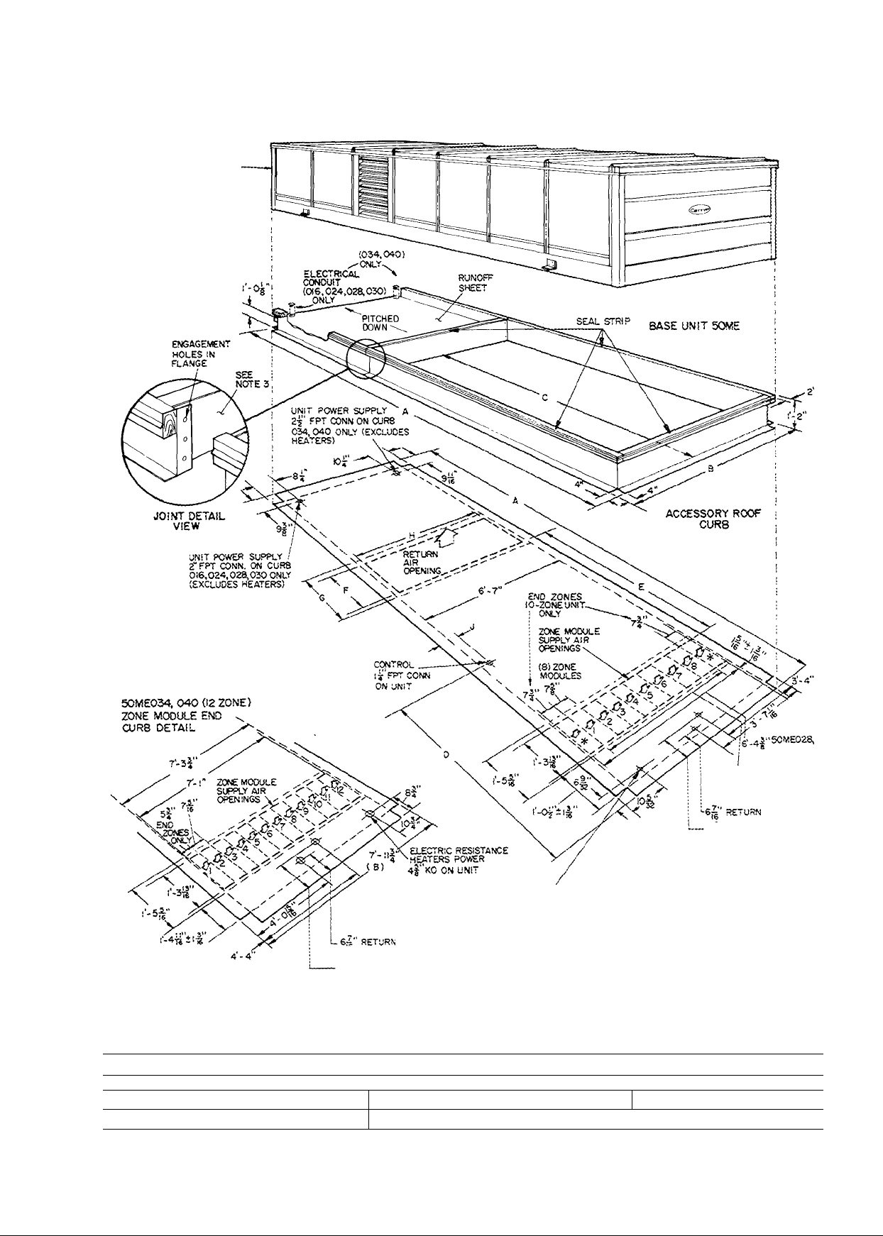
Roof curb supports unit and frames
roof openings to provide a strong,
watertight interface between unit and
roof. Galvanized, 14-gage steel, 2-piece
construction minimizes installation time
and costs. (Accessory)
Modulating outdoor air control pro
vides year-round ventilation with out
door air. An outdoor air thermostat
locks out compressors to permit “free
cooling” with outdoor air. (FactoryInstalled Option)
Roll filter package includes 65 ft of
2-in. thick filter media, automatic media
advance switch and a motor. The run
out switch turns on the filter light in the
remote control center to show when the
media needs replacing (FactoryInstalled Option)
Powered exhaust damper has con
trols to operate outdoor air fans to
exhaust return air when unit is in “free
cooling” mode. (Factory-Installed
Option)
Cooling only unit (SOME) — Unit is
available with all heating controls but
without heater assemblies. Included are
24-volt control circuits and 115-volt
power terminals for 2-stage control of
steam heating coils field installed in the
unit or in the zone ductwork.
t
Electric heat (SOME) — Each zone
module is equipped with its own inde
pendent heater assembly. Two- and
3-stage heat is available to provide close
air temperature control without wide
temperature swings associated with
rapid-cycle, full-on, full-off systems.
Three heat-to-cool ratios are avail
able: .75.1, 1.1 and 1.5:1 to match
almost any heating load requirement.
(Factory-Installed Option)
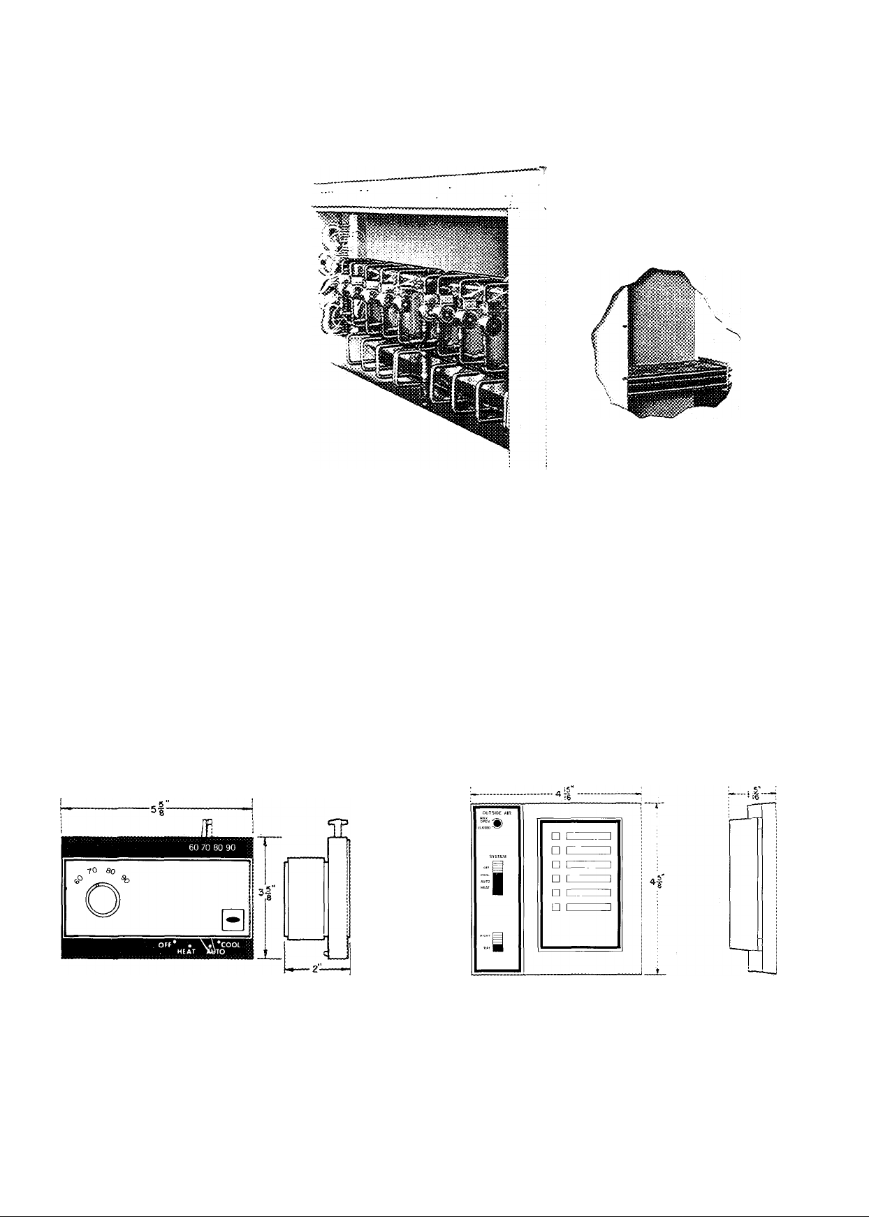
Zone thermostat (24 volts) provides 2-stage heating
and one- or 2-stage cooling for control of individual
modules. Matching subbases are available with or with
out tamperproof switches and automatic changeover.
(Accessory)
Remote control panel (24 volts) — This decorative
central control for the entire unit has switches for HEAT,
COOL, AUTOMATIC CHANGEOVER, OFF and
DAY/NIGHT settings; dial to adjust outdoor air damper
to rapidly ventilate conditioned spaces. A dirty filter
warning light and knockouts for additional warning lights
are also provided. (Accessory)
Page 7
*hysiccd data
UNIT 48MA/50ME
Zone Modules
Nominal Cooling Capacity (tons) 15
OPERATING WEIGHT Tib)
Base Unit 48MA 3385
Base Unit SOME (with heat) 2985
Roof Curb 506
REFRIG CHARGE (lb, R-22) 28
COMPRESSOR
No. 1 Type
Cylinders. Unloaders 6 2
No. 2 Type
Cylinders (has no unloaders)
System Oil Charge (pts)
Unloader Settings (psig)
Left Bank
Right Bank
Capacity Steps (%) 100,67,33
OUTDOOR AIR FANS
Motor Hp .Rpm...Frame (NEMA)
Nominal Cfm
INDOOR AIR FANS
No. ...Size (in.)
Cfm (Nom) 6000
Motor Hp .Rpm
Fan Pulley
Outside Diameter (in )
Bore (in.)
Fan Belt No ..Size w/Std Mtr
Motor Pulley A
OutsideDiam(in.) w/Std Mtr
Bore (in.) 1-1/8
Resulting Fan Rpm w/Std Mtr 880
Motor Pulley B
Outside Diam (in.) w/Std Mtr 60
Resulting Fan Rpm w/Std Mtr
OUTDOOR AIR COOLING COIL
Face Area (sq ft)
Corrugated Fins/in ...Rows
EVAPORATOR COILS (zone)
No. ...Face Area (sq ft, ea)
Corrugated Fins/in .Rows
HEATING SECTION (48MA)
Rise Range
Input (1000 Btuh) Total
Bonnet Cap (1000 Btuh) Total
HEATING SECTION (SOME Electric)
Electric Heaters
No . .Elements (ea)
fiiMTNG SECWON (ici/ii*GTvcoii
Max Allowable Inlet Temp
Max Allowable Flow, Each Coil
Solution Mixture
Max Allowable Working Pressure
Total Internal Volume (gallons)
PRESSURE SWITCHES
Low-Pressure
High-Pressure
Indoor Airflow Switch (AFS 1
Factory Setting (cfm)
Adjustment Range (cfm)
INDOOR AIR FILTERS
Std No. ..Size (in )
High Efficiency (optional)
m
No. . Size (in )
Roll Media (optional)
OUTDOOR AIR FILTERS
No . Size (in )
No 1
No. 2
No 3
w/Opt Mtr
w/Opt Mtr
w/Opt Mtr
w/Opt Mtr
w/Opt Mtr
Each Module
Full Rate
Cutout
Cut-in
Cutout
Cut-in
016 024
8
06DE537
—
—
.... " .
— — —
16,500 15,000
2 15x15 2 15x15
5 1725
10 6
1-3/16 1-3/16
1 3V630 1 3V630
—
5 3
— — — —
—
—
995
—
68
13 2
8. .2 12
13 3
432
54
324
40 5
8 2 or 3
2 61
■ or 3-Stage, Nichrome, Open-Wire Flesistance Elements in Each Zone Module
8 10 10 12
20 25
3805
3405
506
32 43
06DE824
6.2 6 ..2
06DA824
6
22
100,83,67
50,33,17
8000 10,000 10,000
7-1/2 1725 10 1725 10 1725 15 1725
10 6 80 80
60 50 50
1-3/8 1-3/8 1-3/8 1-5/8 1-5/8
995
— —
69
— —
1145
—
Thermostatic Expansion Valve, Hot Gas Bypass
68
13 2
8. .2 12
13 3
432
54
324
40 5 40 5 40 5 40 5
8 2or3 J_ 10 2 or 3 I 10 2 or 3 [ 12 2 or 3 |
2 61
6000
4000-600
Same but with 36 5% efficiency (NBS Dust Spot Test)
2 20 X 25 X 1
028 030 034 040
4075
3665
506
Reciprocating Hermetic. 1725 Rpm
06DE537
06DA824 06DA537 06DA537
6 6
22 22 21
Compressor No 1 Only
71 0 ± 1 5
57 5 ±25
760 ± 1 5
62 5 ±25
100,80,60
40,20
Propeller, Direct Drive
1 1075 56(1-phase)
1 1140 56 (3-phase)
15,000
Centrifugal; Belt Drive
2 15x15 2.15x15 3..15x9 3. .15 X 9
1-3/16
2 3V560
—
Factory Installed
1095
Shipped With Unit
56
1230 1230 1230 1230
—
6 8
1
13 2 13 2 i
Solenoid Valve and Capillary Tube for each
I 10.212 I 10.212 I
Furnace Assembly in Each Zone Module
25 F to 55 F at 0 75 in wg ESP
540
54
405
One Heating Coil in Each Zone Module
3 15 3 15 3 76 3 76
65 ft of 2-in media
6 8
I
13 3 j 13 3
200 F
6 Gpm
20% Glycol
30 Psig
29 + 5 Psig
39 ± 5 Psig
400 ± 5 Psig
300 ± 5 Psig
12 20 x 25 x2
28 30
4080
3670 4400 5250
506
43
06DE537
6.2
100,80,60
40,20
-
15,000
1-3/16
2 3V560
—
1095
—
5 6 5 6
—
—
I
540
54
405
4800
630
57 66 1
06DE537 06EE250
6.2
6
75 5 ± 1 5
58 0 ± 2 5
100,83,67
50,33,17
1.1140 56 (3-phase)
24,000
12,000
20 1725
8.0
1-11/16 1-11/16
2 3V630 2 3V630
3 3V670
50
6.0
1095
1320
6 5
1425
102
13 2
12.201
12 3
648
54
486
9000
6000-9000
2 32 X 35 X 1
12
37
5700
630
4.1
06EA250
4
31
—
100,75,
50,25
23,000
12,000
15 1725
20 1725
80
3 3V670
50
6.0
1095
1320
56
6 5
1425
102
13 3
12.201
15 3
648
54
486
40 5
12 2or3
Page 8
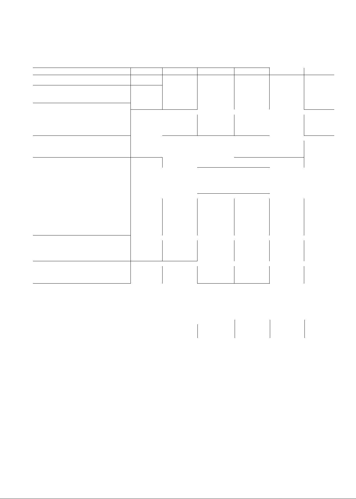
Roof curb dimensions (48MA)
COMPRESSOR, CONDENSER
AND CONTROL BOX END '
OF UNIT
Certified dimension drawings available on request.
UNIT
48MA 1
016,024,028,030
034,040 i
A 1 B
]B- 2% Î 7-3
21-1 r/j 1 7-ll-y<
48MA0M. 040 02 ZONE)
ZONE MODULE END
CURB DETAIL
I c
1 D
i n-9
Î 14-iy
DiMENSiONS (ft-in.)
i........E
.5-6 V,
6-7’/,,
......
i 7-2%
i 8-4%,
MAIN GAS l3 FPT CONN
ON SASE UNIT
evaporator (ZONE MODULE ¡AIRFLOW
* NOT USED ON 48MA0t6,024(8 ZONE
NOTES- I FOR additional INFORMATION SEE
; F
Î 1-10%,
Î 2- 9% j 3-1
module UNITS)
BASE UNIT PH.YSICAL DATA AND
DIMENSIONS
2 MAXIMUM ALLOWABLE UNIT PITCH IS
jlN IN lOFT IN ANY DIRECTION
3 REMOVE SHIPPING BRACE BEFORE
ASSEMBLING CURS SECTION
(LOCATION SHOWN).
i G
i H
1 2-2%, I 6-0%
! 6-8% i 0-10%,
'6'.4|"4SMA028,
'030 (10 ZONE MODULES)
5'-r 48MA016, 024
(8 ZONE MODULES)
1 J
1 C- 7%
Page 9
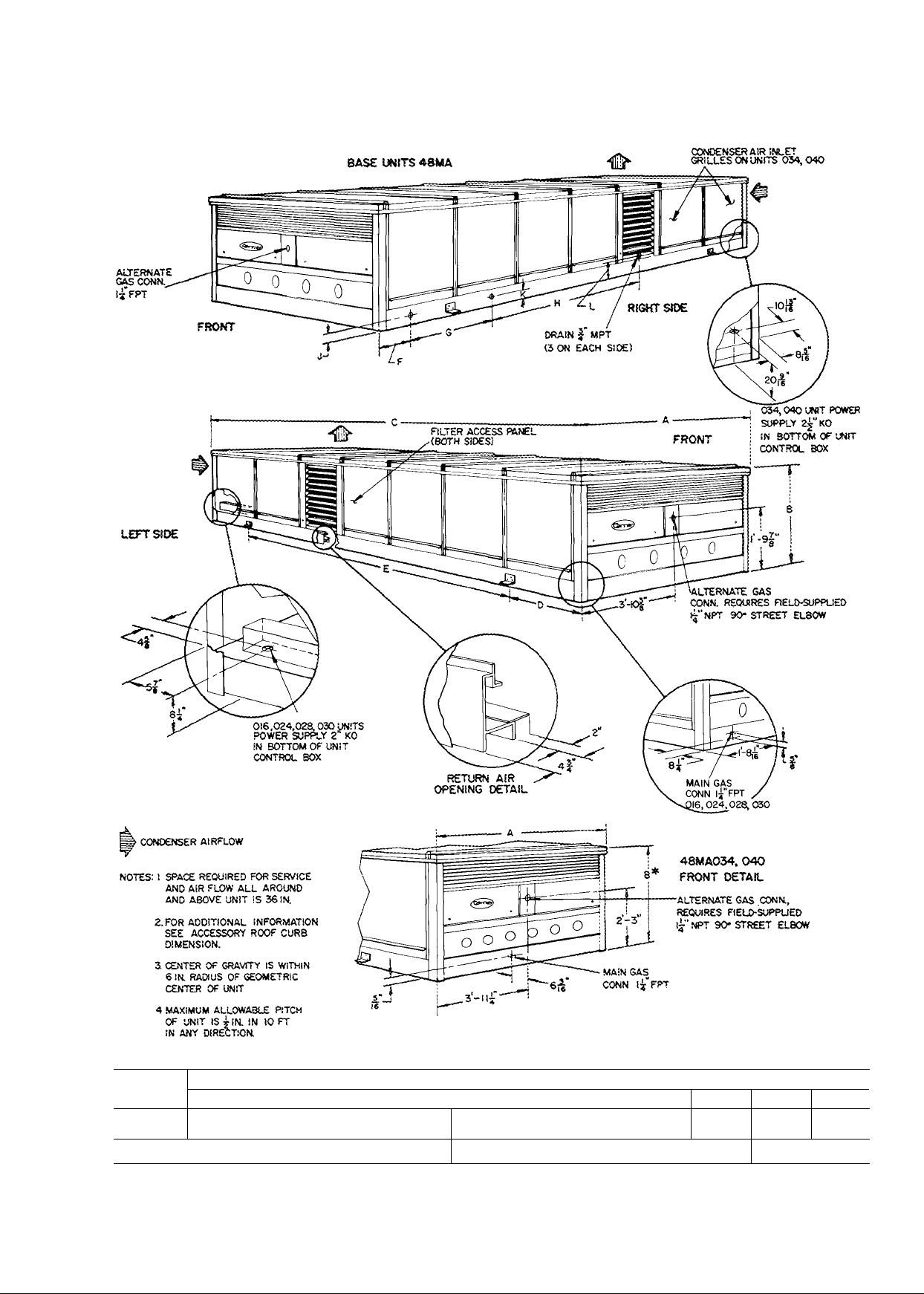
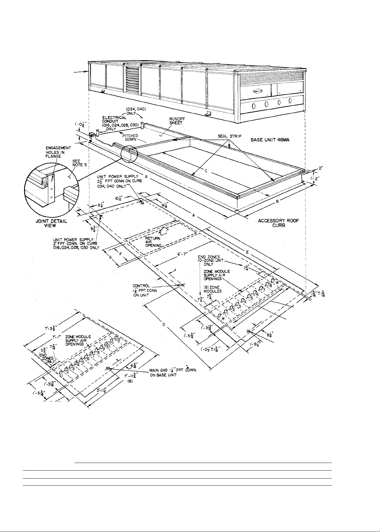
Base unit dimensions (48MA)
Certified diiTiension drawings avaiiabie on request
UNIT
m
48MA
016,024,
028,030
034,040
*Ovsra!i height: induces 1 3/4-in for fan guards WSMA034 an.d 040
i A
1 7- 21^
1 7-n
lJ
_______
i B I c
f
----------------
I 3-0%
1
“T
-----------------
i
; 21 - 9%«
; 0
1 2-2*%s
1 4-2
DIMENSIONS (ft-
1 !3-5%
i i3-5%
!
1 0- 9^6
in.)
1 G
i 2-10
i 3- 4%s
1 ”
1 7-3%« r /«
I 8-6% 1 0-3
i ■)
0-3%
K
L
0-3%
0-7%
Page 10
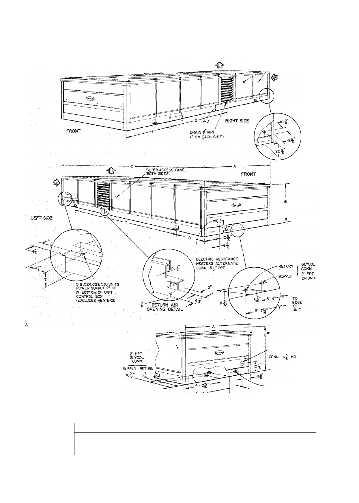
Base unit dimensions (SOME)
BASE UNfT SOME
CONO£NS£R AIR INLET
^ GRILLES ON UNITS
034,040 UNIT POWER
SUPPLY 24" KO
IN BOTTOM OF UN!T
CONTROL SOX
(EXCLUDES HEATERS)
034, 040
t
• CONDENSER AIRFLOW
notes: I SPACE REQUiRED FOR SERVICE
AND AIR FLOW ALL AROUND
AND ABOVE UNIT IS 36 iN.
2 FOR ADDITIONAL INFORMATION
SEE ACCESSORY ROOF CURS
DIMENSIONS.
3 CENTER OF gravity IS WITHIN
6IN RADIUS OF GEOMETRIC
CENTER OF UNIT
4 MAXIMUM allowable PITCH OF
UNIT IS -¿-IN. IN lOFT IN ANY
DIRECTION.
UNIT
SOME
016,024.028.030
034,040
^■Overaü r.eigdt, inciudes ' 3/4 in fc* fan guajds .(oOV-ЕОЗА and 0^0).
A
7- 2%
7-1 i
i ®
: 3-0^«
i 3-9”/.** 21- 9Мб i 4-2% ! 13-54 i
DIMENSIONS (ft-in.)
j 2-2^5<* 1 13-54 i
10
c i D . j E i
ELECTRIC RESISTANCE
HEATERS MAIN POWER
_
_______
G
ELECTRIC resistance
CONN. 4|" KO
: Я
i 0-2‘4б
T| heaters main POWER
Certifiées dimensior> drawir^gs avaueble ori request.
F
3-74* i 7-34* i 0-34
4-4 г 8-64
i J
i 0-34
i 0-74
Page 11
Roof curb dimensions (SOME)
COMPSeSSOR, CONDENSER
AND CONTROL SOX END
OF UNIT
Certified dimension drawings available on request
--------------------------—J
------------
UNIT 1
48MA A
016,024,028,030 1 IS- 2%
034,040 j 2i-n%
ELECTRIC resistance
HEATER POWER
Ag'KO ON UNIT
) GLYCOL CONN
-10Й SUPPLY’
I г"РРТ ON UNIT
DIMENSIONS {ft-in
В {
7- 3 !
n-9
i D i E i F
c
i S-6% 1 7-2% 1
7-11% : ;4-l% i 6-7%« i 8-4%« j
11
5' 50ME0I6.024
ЮЙ' SUPPLY GLYCOL CONN
2"PPT ON UNIT
if) evaporator (ZONE module; AIRP'lOW
* not used on 5CWE0I6,024(820NE
NOTES- 1 POR ADDITIONAL INFORMATION SEE
module UNITS)
BASE UNIT PHYSICAL DATA AND
DIMENSIONS
Z MAXIMUM ALLOWABLE UNIT PITCH IS
■jlN IN ЮРТ IN ANY DIRECTION.
3. REMOVE SHIPPING BRACE BEFORE
ASSEMBLING CURB SECTION
(LOCATION SHOV/N)
)
i G
i H
1-10%« i 6-0%
2- 9%
iilL
i 6-8%
030 OOZONE
MODULES)
¡8 ZONE
MODULES)
] J
I 0- 7%
i 0-10%«
Page 12

Selection procedure (with example)
Refer to Carrier’s Engineering Guide for Multizone Unit
Systems and contents of this booklet for typical multizone
design considerations. Using the Engineering Guide, cal
culate cooling and heating load estimates for the areas to
be served by the multizone unit. Divide each area into zones
based on the peak load and control requirements within
the area.
The resulting loads calculated for a typical building are;
Cooling
Grand Total Load (GTL)
........................................
272,440 Btuh
Sensible Load (SL) .................................................. 219,000 Btuh
Room Design .................................................... 75 F db/50% Rh
Outdoor Air (OA) Cfm............................................................1000
OA Ambient Temperature
..............................
95 F db/75 F wb
Electric Power Source...................................................... 460/3/60
Zone No. (RTL)/Zone (RSL)/Zone
1 19,000 Btuh 16,935 Btuh
2 25,000 Btuh 22,505 Btuh
3 25,000 Btuh 22,505 Btuh
4 70,000 Btuh 59,160 Btuh
5 22,000 Btuh 19,720 Btuh
6 25,000 Btuh 22,505 Btuh
7 40,000 Btuh 33,870 Btuh
Total 226,000 Btuh 197,200 Btuh
*Loads are peak loads
Room Total Load* Room Sensible Load
Heating (Electric Resistance Heat required)
Zone No. Heating Load/Zone Electric Resistance/Zone
1 34,000 Btuh 10 0 kw
2 44,000 Btuh 12 9 kw
3 44,000 Btuh 12 9 kw
4 111,000 Btuh 32 5 kw
5 42,000 Btuh 12.3 kw
6 44,000 Btuh 12 9 kw
7 81,000 Btuh 23 7 kw
Total* 400,000 Btuh 117 2 kw
*Zone Peak Capacities
Selection:
Base the multizone unit selection on cooling load require
ments. Enter the 48MA/50ME rating tables in the Per
formance Data Section and select the unit that meets or
exceeds the grand total load at the specified conditions.
(Interpolation may be necessary to obtain unit rating at
certain conditions; extrapolations are not advised. Contact
Carrier Application Engineering tor performance data at
points beyond the range of published tables.) Tbe 024 size
unit does not have sufficient capacity to meet load
requirements at any cfm. The 028 size exceeds load require
ments; however, it is the smallest unit that meets specifica
tions. Thus, the 48MA/50ME028at: 9000 cfm; 1000 cfm OA;
95 F/75 OA temperature; and 75 F/50% Rh room design has
a Total Capacity (TC) of 282,000 Btuh, Sensible Heat Ca
pacity (SHC) of 219,000 Btuh and a compressor kw of 27.5.
Calculate the Room Total Capacity (RTC) and the Room
Sensible Heat Capacity (RSHC) by deducting the outdoor
air load from the unit capacity. The outdoor air load with
respect to room conditions is:
Total Heat (OATH) = 4.5 (hoa - hroom) (OA cfm)
= 4.5 (38.61 - 28.29) (1000)
= 46,440 Btuh
Sensible Heat (OASH)
- 1.09 (toa - troom) (OA cfm)
= 1.09 (95 - 75) (1000)
= 21,800 Btuh
The unit capacity available to offset room loads is:
RoomTC = UnitTC - Outdoor Air TC
= 282,000 - 46,440
= 235,560 Btuh
Room SHC = Unit SHC - Outdoor Air Sensible Heat
= 219,000 - 21,800
= 197,200 Btuh
For comparison.
Actual Load
GTL = 272,440 Btuh
SL = 219,000 Btuh
RTL = 226,000 Btuh
RSL = 197,200 Btuh
Actual Unit Capacity
TC = 282,000 Btuh
SHC = 219,000 Btuh
RTC = 235,560 Btuh
RSHC = 197,200 Btuh
The 48MA/50ME size meets or exceeds the total and zone
load requirements at the specified conditions. The excess
RTC decreases space average relative humidity slightly
below the room design of 50%. By increasing air quantity
above 9000 cfm, this excess latent capacity can be
converted to additional sensible capacity if desired.
Since the modular multizone is a constant volume
machine, proportion the selected supply cfm per zone to
satisfy each zone’s peak load condition.
Divide room sensible capacities (RSC) equally among
the modules if an equal cfm is going to each. In this
example, the 48MA/50ME028 has 10 modules and the
nominal cfm is 900 cfm per module and equal cfm’s are not
going to each.
Vary the cfm to each zone (with field-supplied manual
dampers in zone ducts) to match different zone require
ments. Since the original rating was based on 9000 cfm
supply air, all variations must total 9000 cfm. When the cfm
is changed (by some percent) from the nominal in a specific
module, use the room capacity multipliers in the Zone
Cooling Capacity Multiplier Table to correct room TC and
room SHC for that zone. Capacity versus cfm changes for
the example is given in the Capacity vs Cfm Change
table.
By analyzing each zone’s ratio of deviation from equal
sensible heat allocation, determine the proper cfm change.
In the example, if building room SHC is 197,200 Btuh and
10 zones are used, each zone’s normal room SHC is
19,720 Btuh. But if Zone 3 has 22,505 Btuh room SHC, then
by ratio of 22,505: 19,720 or 1.14, the cfm change is +20%.
Correspondingly, if Zone 1 had 16,935 Btuh room SHC,
the cfm change is -20%.
In applications where the zone selection is not an incre
ment of the number of unit modules (i.e. one zone requiring
500 cfm in a 48MA/50ME028 with 10,000 cfm), refer to
Module Cfm Limits (page 36), Application Data section for
details on using cfm’s below 600 cfm/module.
Formulas required to use ratings are:
Outdoor Air Total Heat (OATH)
OATH = 4.5 (OA cfm) (hoa - hroom)
12
Page 13

CAPACITY VS CFM CHANGES
ZONE
NO.
NO. OF RSL/ZONE
MODULES
...
1
2
3 1
4
5
6
7
RSHC — Room Sensible Heat Capacity RSL —
10 197,200
PEAK LOAD (RSL/NOM UNIT RSHC) FROM NOMINAL UNIT RTC
1 16,935
1 22,505 22,505/19,720
3 59,160
1
1 22,505
2 33,870
22,505
19,720
22,505/19,720
59,160/3 X 19,720 =
22,505/19,720 1 .14 : +20 1080 1 11
33,870/2 X 19,720 =
% DEVIATION
16,935/19,720
19,720/19,720
.86*
1.14
1 .14
1 00
1.00
86
Room Sensible Load
ZONE COOLING CAPACITY MULTIPLIERS
%
CFM CHANGE*
+ 35
+ 20
+ 10
0
-10
-20
-35
*Must not be greater than 1200 cfm nor less than 600 cfm per module,
tlf resulting RSHC is greater than RTC, then RSHC equals RTC
ROOM TOTAL
CAPACITY
(RTC)
1.15
1.10
1.05
1.00
0 95
0 90
0 85
ROOM SENSIBLE
HEAT CAPACITY
(RSHC)
1.14t
1 07t
1.00
0 93
0.86
0.79
Outdoor Air Sensible Heat (OASH)
OASH = 1.09 (OA cfm) (toa - troom)
Room Total Capacity (RTC)
RTC = Unit TC - OATH
Room Sensible Heat Capacity (RSHC)
RSHC = Unit SHC - OASH
Leaving Air Temperature (LAT)
TAT + + RSHC
LAT = room temperature - ^ Q'^f^
Determine Heating Capacity:
The specified requirement for electric heat dictates the
selection of a 50ME028 unit with a kw option that meets
or exceeds the heating load.
The Electric Resistance Heater Data table (page 30) indi
cates that the 028 unit has heating capacity options of 66,
88 and 132 kw. The 132 kw option is selected as it provides
adequate heat for this application. The kw/zone and
number of heat stages available are:
Zone No. Load
1
2
3
4
5
6
7
Total
10.0
12 9 kw
12 9 kw
32 5
12 3 kw 13.2 kw
12 9
23 7
117 2 kw 132 0 kw
Zone Heating
Capacity
kw
kw
kw
kw 26.4 kw 6
13 2 kw 3
13 2 kw 3
13 2 kw 3
39 6 kw 9
31 2 kw
Stages
of Heat
3
3
30
% CFM CHANGE
-20 720 i 9
+20
+20 1080 1 11
0
0 900 ! 1 .0
-20 1440 1 .9
Stages of heat are controlled individually in the small zones
or collectively in large zones to provide flexible and
continuous control for each zone.
Determine fan requirements
For 48MA/50ME operation, cfm range per module is 600
to 1200 cfm. Lower flow volumes are permissible if only
first stage of heat is operated. Volumes above 1200 cfm
may cause water blow-off during cooling.
Since the various unit zones operate at different air
quantities and different external resistances, identify the
zone having the highest static pressure requirement for
the supply duct and supply outlet.
Usually, the longest duct run to the last outlet, with the
greatest number of offsets and elbows, has the greatest
static pressure requirement. Assume a duct friction analysis
has been made and the cfm and static pressure are:
Zone No. CFM
The total unit (02810or 030) cfm is 9000. Zones 4 and 7 have
3 and 2 modules, respectively, “ganged” together to comply
with the limitation of 1200 cfm per module
The cfm for Zone 2 is 1080 with an ESP of 0.8 in. wg. This
module appears to possess the highest friction loss. There
fore, the main fan static pressure is established at 8 in. wg
ESP.
Enter Fan Performance table at 9000 cfm, .8 in. wg ESP
and read: 1020 rpm and 5.4 bhp. The 028 indoor fan motor
data shows the standard 10 hp motor with a maximum bhp
of 11.5. Therefore, 5 4 bhp for this selection is satisfactory.
In the Physical Data table, 2 pulley selections are available
with the 028: Pulley A, shipped mounted; Pulley B, shipped
in the blower compartment. Pulley A has a fixed pitch and
at 1095 rpm is close enough to the required cfm and should
be used. Pulley B at 1230 rpm allows selection of the unit
at higher cfm’s and static pressures.
13
jUNIT TOTAL
CFM3 CAPACITY
Imultiplier
1080
1
11
2700 i 1 0
9000 j
RTC — Room Total Capacity
ESP (in. wg)
1
2 1080
3 1080
4 2700
5
6
7
Totals 9000
720
900
1080
1440
UNIT
NOMINAL
RTC/ZONE
X
23,556
X
23,556
X
23,556
X
3 X 23,556
X
23,556
X
23,556
X
2 X 23,556
No. Modules CFM/Module
6
8
5
6
4
4
5
1
1
1
3
1
1
2
ADJUSTED
21,200
25,912
25,912
70,668
23,556
25,912
42,400
235,560
720
1080
1080
900
900
1080
720
Page 14
Performance data
Room Design 75 F/50% Rh
OUTDOOR
R
Db
Wb
85
90
95
100
105
no
115
OUTDOOR
TEMP
Db Wb
65 204
85
70 204
65
70
90
73
75
65
70
95
75
78
80
70
100
75
78
70
105
75
110
78 183 133
115 75
0 750
TC SHC Kw
65
168
70
168 J18
65 164
70
164
73
164 116
75 164 116
65
I6U
70
160 114
75
160 114 16 0 173 121 16 6
78
160 114 16 0 175
80
160 114
70
156 112
75
156
78
156 112 16 5 171
70 152
75
152 no 17.0
78
148
75
144 107 18 0
TC SHC Kw TC
200 141
200 141
200 141
200 141
196 140
196 140
196
196
196 140
192 137
192
192 137
187 1 35 20 9
187
178 131 22 3 191 155 23 3 200
14 8 174
118
14.8
116 15 4 169
116 15 4 173
15 4 176
15 4
114
16 b
16 0 169 126 16 4
16.0
16 5"^
112 16 5 168 123 17 2
no 17 0 160 130 17 5
109
17 5
0
143
18 0
143
18.0
18 8 208 155 19 2
18 8
18 8
18 8
19 5 203 157
19 5
140 19 5 212
140 19 5
19 5
20 2
137 20 2 207 150 21 2 216
20 2 209 147
135 20 9 201
21 6
4,000
Outdoor Air Cfm
TC SHC Kw
126 15 1
178 122
177
165 131
177 116
164
164
161 124
155
Outdoor Air Cfm
212
217
212
215
216 146
207
214
216
202
197
199 150 22 8
15.3 184
129
15 7 172
124
15 9 179 131
121 16 0
119 16 1
16 2
118 16 8 186
16 9
128 17 0
120 17.4
125 17 8 172
18 5 171 139 19 1 154
130
18 8 162 152
5,000
750
SHC Kw
153 18 5 216 161 18 7
149
18 7
151 19 5 219
148 19 6
19 7 227
19 9
153
20 2
148 20 5 222 154
145 20 6
143 20 8 230
155 20 9 209
21 4 221 154
157 21 6 204
152
21 9 211 166
1500
TC
177 134 15 2
183 125
186 121
168
174 137 16 7
182 127 17 1 167
189
170 143
177 133 17 7 163 124
181 127 18 0 163 124 16 9
165 149 17 9
TC SHC
224
212 167
224 152 20 1 210 159
208 173 20 2 206 157
214
227
210 166 23 6
Kw
SHC
15 6
124
15 8
140
16 2
16 4
16 5
146 16 4
17 4
121
116 17 5 167
17 3
139 18 3 158 123 17 4
19 4
1500
Kw
19 1 215 161
152
19 4 210 159 19 3
158 19 9 210 159
148 20 3 210
164
20 6
21 1
148 21 4
144
21 6
170 21 3 201
160
21 8
22 1
176
22 1
22 6
24 0 186 149
178
0
TC
SHC Kw
130
176
176
130
171
128 15 8
171
128 15 8
171
128
171
128
167 126
167 126
126
167 126
126
163 124
158 123 17 4
121
149 119
0
TC
SHC Kw
215 161
206
206
206
206
201
201
196
196
191
18 6 222
18 6
19 3
19 3
159 19 3
20 1
157 20 1
157
20 1 220 1 66 21 0 229
157 20 1
157 20 1
155 20 8 211 172 21 5
155 20 8 214
155
20 8 217
153
21 5
153 21 5
151
22 2 206 168 23 3
22 9
COOLING CAPACITIES
TOTAL UNIT CFM
5,000
Outdoor Air Cfm
750
SHC K w TC SHC
TC
15 2
181 139 15 4 184 146 15 6 181 142 15 4 186
15.2 184 134
176
179 136 16 2
15 8 182 133
15 8
183
16 3
172
16 3
175 138 16 8
16 3
178 133 16 9 186 139
16 3
180 130 17 1
16 3
182 128 17 2
16 9
170
16 9
173 136 17 5
175 132 17 6
165 143 17 9
168 138 18 1 175 152 18 5
17 9 166 137
18 4
159
TOTAL UNIT CFM
Outdoor Air Cfm
TC
226 167 19 2
218
221 169 20 0 227 176
223
225
213
216
222 163 21 1
224
205
209
TW 173" 23 8 206
15 6 190 137 15 9
141
16 0 179 152 16 2 176 140 16 0
16 3
131
16 4 191 133 16 8 176
143 16 6 174 158 16 7
141
17 3
18 7 - - -
142 19 1
6,500
750
SHC Kw
171
19"0 226
173 19 8
166
20 1
164
20 2 234 166
175 20 5
171
20 7 222 182
160
21 2 236 162 21 9 212 174 20 5
21 7
168
164 21 9
174
22 2 212 193
169
22 4 217 184
1500 0
Kw TC SHC Kw
181 142
185 143
188
180 149 17 0
190 133 17 6
175 155 17 6
181
170 162 18 2
TC SHC Kw TC SHC Kw
233 170 19 5 222 178 19 0
222 Tss 2b"b 2i7 i76" T9" 7
231
217
233
217
223
227 172
215 184 24 0 197
16 4 176 140 16 0
137 16 6
- -
146 17 9 167
- - -
- -
1500
179
170
191
172 21 5 212 174 20 5
166
188
178
T95" TTT" 191
176
140 16 0
140
172
138
172
138
172
17 4
-
_
19 2
20 3
20 6
20 7
20 8
21 1
21 7
21 8
22 2
22 5
22 6
23 0 202 169 21 9
138
172
138 16 6 184
172
138
167 136
136
167 136 17 2
162 134
162 134 17 7
158 132 is 2 T69
153 130 18 7
222
178
217 176
217 176
217 176 19 7
212 174
212 174
212 174 20 5
207
172 21 2 216'
207
172 21 2 220
207 172 21 2
202
169 21 9
167 22 6
f65 23"3 202
15.4
16 0
16 6
16 6
16 6
16 6
\17 l74
17 2
T7T T69 154^
Outdoor A r Cfm
0
19 0"
229"
232
224
19 7 227
19 7 229
231
20 5 219
20 5
222 187
225
228 179
229 177
222 181 22 2
"2ll
214
210
48MA/50ME016
6,000
Outdoor Air Cfm
750
TC SHC
189 146 15 8 194
181
184
186
187
176
179 150
182
185
177
179 144 17 8
172
162 153‘
Kw
150 15 7
152 ibb 183 1641
148
145
143
155
145 17.1 189
142 17 2
140
152
147
149 18 3
T48
TC
188
16 4
189 155
16 5
192 149
16 6
194
178 170
16.8
183
17.0
17 3
17 5
178 '167
17 7
'18‘T 17l3 173
TF9
19 3
48MA/50ME024
8,000
750
TC
Kw
SHC
i 88"
183
l"90"
185
182
181
191 20 9
182 21 3 233 189
189"
184 22 0 227
19T
186 22 8
185 23 6
T89
TC
19 4
233" 196 19""6
19 5
239 187 19 9
20 1
228 202
20 3 233
20 4
237 187 20 8
20 5 239
223 207
21 1 227
21 4
21 5 - -
21 8 222
22 5"
"21 7 210"
221
24 1
1500
SHC
T58^
149
145
161
151
_
_
- -
__ _
- -
-
1500
SHC
20 4"
193 20 6
183 21 0
21 2
199 21 4
21 8
_
_
204
22 2
195 22 5
- - 22 9
201 23 3
_ _ _
- -
Kw
15^8'
26 1
T6^4'
16.6
16 8
16 9
T7V0
17 2
17 5
T7 8
18 4
kw
_
t
AIR
TFMP
Db
85
95 75
100
lO*'
no
lis
0
Wb
TC SHC Kw
65
265
70
65
70
73 259
75 259
65 254
70
78
80
70 248 182
75
78
70
75 242
78
75
190 24 6
265
190
259
188 24 9
259 188 24 9 274
188 24 9 277
188
185
254
185
254
185
254
185 25 8
254
185 25 8 279
248 182 26 7 266
248 182
242
180 27 6
180 27 6 259 201
236
177
230 174
—
24 0
24 9 279
25 8
25 8
25 8
26 7 261 205 27 6
26.7
28 4
29 2
7,000
Outdoor Air Cfm
1000
TC
SHC Kw
203
275
280 197
269
206
200 25 8 282
196 25 9
193 26 1
262
208 26 4
267
202 26 7
273 196
276
192
189 27.3 294
198 27 9 277 212
269 194
254
207 28 4 261
256
199
246
206
2000 0
Kw
TC
24 6
24 8 289
25 5 273
27 0 284
27 2 290 196
28.1 283
28 8 270 220 29 5 252
29 9 268 219
30 4 256 236 31 2
SHC
280 213
201 25 3 277
221 25 7 271
209 26 2 271
287
201 26 5 271 210
291 196
267 229
275 217
204 27 7 264
190 28 3
268 225
203
233
TC
24 8
277
271
26 7
264
26 6
264
27 1
264
28 0
264
258
28 0
28 6 258
29.0
258
252 202
28 9
245 199
30 8
239
TOTAL UNIT CFM
9,000
Outdoor A ir Cfm
1000 2000
SHC Kw
213 24 6
213 24 6
210
210 25 6
210
ToT 26 5
208 26 5
208
208 26 5
208
205 27 4
205
205
202
197
TC SHC K w
287 226 25 2
291 220
25 6 280 229 26 1 284 244
284
25 6 287 219 26 5
25 6
289
273
277 225 27 3 284
26 5
282
285
26.5 287 212 27.8
270 228
27 4
275 221 28 5 284 235 29 1
27.4
277 217 28.6
28 3 263 230 29 0
28 3 267
29 1
263
29 9
253
25 4
223
26 3 291
216 26 6
27 0 277
231
219 27 5
214
27 7 297 219 28 4
28 2
224 29 3 276
222
30 4 - -
229 31 0 262
14
— — —
TC
SHC
291 236
298 224 25 8 285 234
296 225 27 0 278 232 26 0
299 219 27 2 278 232
292 227 28 1
276
- - -
269 255 29 5
25 4
26 3 278 232 26 0
232 26 7 278
252 27 2
240 27 7
-
-
248
28 6
243 30 0 258 223
258 31 7
—
0
Kw TC
SHC
285 234
232
272 229 26 9
272 229 26 9
272 229 26 9
272 229 26 9
272
229 26.9 292
265 226 27 8 276
265 226
226
265
258 223 28.7 269
-
221 29 6
251
245 218 30 3
Kw
25 1 294
25 1
26 0 291
26.0 295
27 8
27 8
28 7 273
48MA/50ME028
11,000
Outdoor Air Cfm
1000
TC
298 242 25 8
287
293 241 26 9
280
284
288
291
280 243
283 239
268 243
258 250 31 4
SHC
25 6
248
"26 5
"250"
244 26 7
27 0
238
27 4
252
27 7
247
27 9
240
236 28 1
233 28 2
249 28 6
28 8
29 0
"29 5
252
29 7
245
30 8
Kw
2000
TC
SHC Kw
"298 "258 25 s'
305 246 26 1
"266 26 '7
297 254
302
304 241
"283
290
282 "269
274 274
27 1
246
27 3
27 5
273 27 6
262 28 0
28 9
29 8
Page 15

Performance data
Room Design 75 F/50% Rh
COOLING CAPACITIES
48MA/50ME030
OUTDUUK
Aik
TEMP
Db Wb TC SHC
65 298
оэ
70 298 215 29,7
292 212
65
292 212 30 7
70
292 212
73
292 212 30.7
75
65 285 209
70 285 209
95 75
100 75 279
no 78
115
285 209
285 209 31 8
78
80 285 209 31.8
279 207
70
279_ 207
70 273
273
75
266 201 34.6
261 199 35.5 279
75
- -
OUTDOOR
AIK
TEMP
Db Wb
95 75
100 75 293 240
110 78 279
115 75 273
TC SHC
314 248
65
70 314
307 245
65
70 307 245
307 245 31 8 326
73
75 307 245 31.8 328
65 300
70 300 242 32.8
300
300 242
78
80 300
293 240
70
_293
78
286 237 34 8 300 266
70
286 237 34.8
75
TOTAL UNIT CFM
8,000
Ou tdoor Air Cfm
0 1000 2000 2500 0
Kw TC SHC
215 29 7 311
317 223 30.9 326 228
30 7 304 231 31 6
309 225
30 7
313
315 219 32,3 328
31 8 297
31 8 302
31 8
308
311 217 33 6
314 215 33.8
32 8
207 32 8 300
204 33 7
204
295
.32,8
303
288
33.7 293
289
0
Kw
TC SHC
30 7
326
331 257 31 8 339 262 32.3 312 264
30.7
248
31 8
319
31 8 323
32 8 311
242
242
242
315
32 8 321
32 8 323 251 34 5
325
32,8
33 8 307
33 8 312
33:8 _ ^5
24Q_
304
234
35.7 300
231 36.6
289 264
Kw
229
222
234 32 6 303 255 33 0 305 264
228
222
230
224 34 4 312 237
220 34.7
232
226
224
231 37.1 291 260 38.2
---
Outdoor Air Cfm
1000
263
265 32 5 324 281 32 9
259 32 9 331 269 33 4
256
253
267
261 33 9 323 276 34 4
255
249
263 34.9
257 35 3
253
25?
257 37.4
TC SHC Kw TC SHC Kw TC SHC Kw TC
317
30 5
31 9 318
32 2 324
33 0 311
33 4 320 230 34 2
34 0 303
34 9
35.4
36.6 303 244 37.7
11,000
Kw TC SHC
31 5
33 1
33.2
33 9
34 3
34.6
35.5
35 9 309 290 36.6
36,3
38.0
240
30.9 319
309 247
326
330 216
.3L8.
297 258 35 7
304
—
332 273
336
339 256 33.9
317
330 263 35 0 334 267
335
-
315 283 35 5
322
327 263
3_13
300
31.5
31 9 312
235 32 5
228 32 9 328
222
33.2 333 234 33.5 303 235 31.5 325
243
33 6
222 34 7 332
34.9 337 216 35.4 296 232 32.5 322 237 34.4 336
34 6 307
250
35 3
229
,35J_
245 36.3 309 254 36.6
2000
Kw TC SHC
31.8 334 278 31 9 317 259 30 9 330
261 33 7 339 264
287 34 1 319 297 34 2 303 253 33 0 314 277
35 3
255
„
- - -
271 36 0 326 277 36 3 296 250 34 1 315 268 35.5
36.4
278_ 37,0 -
- ~ - -
293
38 9
245
329
230
254
322 240 32 8 303 235
230
314
250 33 8 296 232 32 5 312
234 34 6
325
223 35 1
260
317 244
324
. 23A
300 269 35 9 282 226 34 5 296 255
254
308
296
274
—
2500
326
288 33 1 310
334
274
343 257
325 283 34 6 303 253 33 0 319 272
_ -
292
318
302
311
- - -
31 0 309 238 30 4 322
31.7
309 238
32 1 303
33 2 303 235
33 2 296
296
296 232 32.5
34 9
289
35 6 289 229 33 5 304
36.1 .289
282 226
276
38.1
270 220 36 3 287 253 37.8
38 6
TOTAL UNIT CFM
—
—
—
Kw
TC SHC
32.5
317 259
33 6 310
33 9 310
34.2
310
303 253 33 0
35 2
303
-
303 253 33.0 328 258 34.8
296 250 34 1 310 274
35 7
296 250 34.1 318 263 35,7 - -
36 8 289 247 35 1 303 276
__
289 247 35J
282 244
276 241 36 8 292 275 38.3
10,000
Air Cfm
Outdoor
1000 2000 2500
30.4
235
31 5
31 5
31 5
232
32 5 307
232 32 5
229
33 5
33,5
229
34.5 301
35.4 297
223
SHC
252 31 2
246 31,5
327
254 32 3
315
320 248
323 245 32.8 332 251 33 5 336
242
256 33 3
251 33 7
244 34 0
317
320 240
304
253
246 35 0
242_ 35_.3_
312_
249 36.0
247 37.2
TC
Kw
328
335
320 270
32 6
328 258 33 1 331
33,0 336 245 33.7
314
319 266 34 2
328 253
34 2
333 244 35.1
34 7
312 273 35 2 315 282
319 260
32A
35 6
305 280
3J.1
- -
297
Kw
TC SHC
334 268
331
323 265
326 261 34 7
367
302
- -
12,000
Air Cfm
Outdoor
Kw
TC SHC
273 31 7 335 284 32 0
342
32.Q_
32 8
328
33 1
266 33 3
263 33 4
270
268
334
338
341
33 9
321
34 1
326 287 34.6 328
34.5 333 274 35 1
-
35 2
318 294 35 7 321 303
324
36 1 311
36.5 316
- - - - -
37 6
- - - - -
— —
0 1000 2000
30.9
256 32 0 322 275
256 32 0 327 270
256 32 0 329
256 32.0
253
33 0
36.0
Kw TC
SHC
263
31 6
251 32,1 339
32 7
SHC
330 267
322
340 246
277
238 35.4
252 36.2
268 36,8
282 38.7
316
33.8
322 273
34 8 332
324 267
35.8
36 3
308 291
3]5 276
302 296
Kw TC
—
- -
-
_
2500
SHC
337
2?2
291 33 1 330 298
280
272 33 9
267
298
_
- - - -
281 36 2
300 36 8 314
28? 37,2 - -
3A5
32,5
33 6 337 284
342
34.1 345 268
34 3 323 307
-
- _ -
-
r
253
277
263
253
286
257
289
274
275
294
312
31 7
32.3
32 8
33.3
33 7
34-0
33 9
34.4
35 1
_
35 5
36 1
36 6
37.1
39 1
32.1
32.7
33 3
33 8
34 1
34 3
34 4
34 8
-
35 9
-
-
37 0
#
Kw — Compressor Motor Power Input
SHC — Sensible Heat Capacity (1000 Btuh)
TC — Total Capacity (1000 Btuh)
NOTES: 1. No values are given where unit cannot maintain the assumed room
design relative humidity since the moisture content of the air leaving
the unit is higher than the assumed room moisture content
2. Ratings are gross and do not include fan motor heat deduction.
15
Page 16

Performance data
Room Design 75 F/50% Rh
COOLING CAPACITIES
48MA/50ME034
OUTDOOR
AIR
TEMP
Db
85
90
95 75
100
105
no
115 75
OUTDOOR
AIR
Db
85
90
95
100
105
110
115
_
Wb
tc
65 314
70
65 307
70
73 307
75 307
65
70
78
80
70 293
75 293
80 293
70
75
78
Wb
65 325 254
70
65 318 251
70
73 318 251
75 318
65 310
70
75 310
78
80
70 302
75 302
78 302
70 294
75
78 287
75 279
SHC
231
314
231 28.6
228 29 6
307
228 29 6 324
228 29 6
228 29.6
300 225
300
225
300
225
300
225
300
225 30 7 329
222 31 8
222 31 8 314
222
285
219 32 8
285
219 32 8
’2/8 215
271 212 34 7
TC SHC
325 254
318 251
251 30 2 339
247 31 3 324
310 247 31 3
247 31 3
310
247
310
247 31 3
244
244
244
241
294
241
238
234 35 4 296
0
kw
TC
28 6 326 246
332 240
318 248
328 239
330 236
311
30 7
30 7 316 244 31 6
30 7 322
30 7 326 234
308
31.8 318 236
300
306 242 34 1
33.8 301
290 246 36 1
0
Kw
TC SHC
29 1 336
29 1 341 262
30 2
328 ^270 30 8
30 2 334 264
30 2
337 261 31 3
325 267 32 2
331
31 3
334
337 253
32 4 317
32 4 322
32 4 325
33 4
308 270 34 3
33.4
313 264
34 4
308
__
9,000
0
utdoor Air Cfm
100(
Kw
SHC
29 2
333
29.5 342
30 3 325 264
242
30 6 334 253
30 8 341
30.9
250 31 3
238
231 32.4
246
240
248
345
322 275
326
32 0
336
32 2 343
348
32.7
318 267 33 3
33 1
328
33.3 334
33 8
314
319
240 35 4 316
306 280 37 3
n,ooo
Outdoor Air Cfm
1000
Kw
268 29 7
258 31 4
275 32 1
260 32 5
256
268 33.2
262 33 6
258 33 8
262
268
30 0
31 1
32.7
32 8
34.6
35.9
36 6
343
352
335
343
349
353
332
334
344
350
354
326
335
340
322
325
2000
TC
SHC
257 29 6
245
30.0
30 6
31 1
245 31 5
Kw
240 31.7
32 0
260 32 2
247 32 8
239 33 2
233
33.4
254
33 9
246
34.3 341
278 34 7
262 35 0
261
36 4
2000
TC
SHC
Kw
279 30 1
268 30.5
287 31 1
275 31 6
268 31 9
262 32.1
298 32 5 335
282 32 7
270 33.2 349
262
33.5 -
256
33 8
290 33 8 334
277 34 3
269 34.7
301 35 2 326
284 35.4 3_^
- - - - -
303
37 8
TOTAL UNIT CFM
2500
TC
SHC
336
262
347
247
327
272
339
257 31 4
346
248 31 7
351
242
325
286
330
267 32 4
342
252
350
241
356
234
321
277
333 261
251
319 291
324
271
- - -
312
295
TOTAL UNIT CFM
2500
TC
SHC
345 285
355
270 30 7 329
342 299
347
280 31 8
354
271 32 1
358 264
308 32.7
338
290 32 9
274 33 5
-
- 304 34 3
340 284
- - -
313 35 4
294
-
Kw
TC SHC
29 7
30.3
30 8
32.0
32 2
33 1
33 6
33 9
33T
34 2
34.7
35 0
35 3
243
320
320 243 28.9
313
240 29 9 324 259
313
240 29 9 329 253
313
240 29 9 333 250 31 0
313
240 29 9 335 247
305
237 31’ 0 3T9 ’264’
305
237 31 0 321 256
305
237 31 0
305 237
305 237
233''
298
298 233 32 1
298 233
290 230 33 1
290 230
283 227 34 1
37 8
275 224
Kw
TC
30.2 329
SHC
264 29 3
264 29 3
31 5 322
32.4
_
34 6 306
35.7
-
261
322 261
322
261 30.4 341
322 261 30.4
314
258
314
258
314
258 31 5
314
258
314
258 31 5
306 255
255
306
255
298 251 33 6 311
298 251
290
248 34 6 311 273
282
245 35 6 299
b" 1000
Kw
TC SHC
2ST 331 257 29 5
337 251
327 249 32 3
31 0
330 245 32 5
31.0 333 242
321
313" 257' 33 0
318 251 33 3 331
32.1
322 247
304 ’259”
33.1
310
253
305 251
35 1
0
Kw
TC
257
1000
SHC Kw
340 279
345 273 30 2
30.4 332
30 4
31 5
31 5
31 5
32 6 320 279
32 6 325 273
32.6
33.6 316 275
281
337 275
272 31 4
343
269
328 286 32 3
329
277 32 4
334 271 32 7
337
267
264
340
269
328
281 34 5
279 36 8
10,000
Outdoor Air Cfm
Kw
TC
33F
,348
29.8
30 6
330 276
30 9
340 264
345
31.2
349
31.8 328
31 9
331
340
347
32.6 351
’322
338
33.6
’341 ’
318
34.4
322
35 7 319
36 4 30^
12,000
Outdoor Air Cfm
TC
29.9 347
355
31 0
339
31 3
347
352 279
31,6
355 273
336 309
338 293
347
32 9
352
- - — _
33.0
33 5
329
33 8
337
-
34.0
325
34.8
328 295
36.1
- -
2000
SHC Kw
268
29.8 34T T73
257
30.3 352
30 9
31 4
257
31,7
251 31.9
287 32 3
271
32 5
259 33 0
250
33 4
245
33.6
279
33 6
266 34.1
258 34 5
290
35 0 323
273
35 2
272
36 6
292
37 6~’
2000
K w
SHC
290 30.3
279
30 7
297 ’31 3
286 31 8
32 0
32.2
32.8
32.9
280 33 4
272
33 7
300 34 0
288
34 5 342
_
_ _
312
35 4
35.6
_ _ _
-
2500
tc
SHC
259
338
288
343
269 31 6
350
260 32 0
355 253 39 9
331
297
335
279 32 7
346
263
353 253
326 289
337
273
344
263
302
328 283
_
_
315
307^
’38 0
2500
TC
SHC
349
295
359
^81
’346
3io
350
291
357
282
361
275
338
319
341
301
351
285
_
337
315
295
329
324
-
Kw
30.0
30.5
31 3
32 5
33.3
33 7
33 8
34 4
34 9
35 2
35.5
.. ^
Kw
30 4
30.9
3L7
32.0
32 3
32.5
32.9
33 1
33.6
34 4
34 8
35.6
16
#
Page 17

Performance data
Room Design 75 F/50% Rh
COOLING CAPACITIES
48MA/50ME040
OUTDOOR
AIR
TEMP
Wb TC SHC
Db
85
90
95
100 75 355
105
no
115
367
65
70 367 262
364
65
364 263 38 3
70
364
73
364
75
361 264 39.8
65
361 264
70
75 361
78 361 264 39 8
361 264 39.8
80
70
355
78 355
351 263 42 8
70
351 263 42.8
75
342 260
78
334
75
OUTDOOR
AIR
TEMP
Wb TC SHC
Db
85
95 75
100
no 78
115
371 273 36 9
65
371 273
70
369 276
65
369
70
369 276 38 5
73
369 276
75
367 279
65
367
70
367 279 40.0 408 311 43 4 418
367 279
78
80 367 279 40.0 415
362
70
75 362
78 362
357
70
357 281 43.1 379
75
349 279 44 7 364
342
75
--
0
Kw
TC
262 36 8
263
263 38 3
263
264 39 8 398
264
264 41 3 383 288 44 6 390
264
257 45.8
402 294 39 0 416 311
36.8 410 290
394 297
38 3
401 293 40 9 412
408
38,3 413 290 41.5
386 300
392
39.8
402 285 43 4 413
405 282 43 6 418
41 3 397
41 3 387
365
368
354
44.3
336 283
11,000
Outdoor
Air Cfm
1000
SHC kw
291
295
289 43 1 408
294
284
294
287 46.1 373 303 47.8 381
280
TC
39.5 426 300 40.8
403
40 4
41 4 419 298
425
390
41.8
42 3 398
43 9 381
44.9 397
364 316 46 9 366 338 48 0 354
45 5
48.2 360 298 50.1 373
49 4 338
TOTAL UNIT CFM
--
2000 3000
SHC Kw
316 41 6 404 330 42 3 366 270 38 4
304
293
321
309
296 44 6 416
287 45 2 427
281
313 45 4 384
300
291 46 7
309 51.3 347
TC
40 2
420
434 305 41.6 368
42 3 418
42 8 427 303 43 7
434 295 44 1
43 1
388
43 1
402 323 44 6
43 8
45 6
433
46 2 399
410
Kw
SHC
322 40 8 368 268
314
43 1
339
43 8
304
45 6
292 46 3 364 272
284 46 7 364 272
331
46 3 359 273
313 47 2 359 273
302 47 8 359 273
322 48.8 354
319 51,4 347 269
336 52 9
—
-
-------
— - --
0 1000
Kw
TC SHC
268
366
270
366
270
366
270
364 272
364 272 39 9 398 307
364 272 39 9
271 43 0 371
271
269 46 1 342
339
TC SHC
36 8 406 302
36.8 414
399 307 40 6
406 303
38 4
38 4 413 303
38.4
419 302
39 9 392 312
404
39 9
408
39 9 411 294
41 5 384 306
41 5 389 300
41 5
393 296
374 299 46.3 378
43.0
44.6
359 291
TOTAL UNIT CFM
13.000
Outdoor Air Cfm
0
Kw
36.9 417 307 39 8 437 322 41 2 446
38 5
276 38.5 409 312 41 2 423 328 42 6 430 338 43 5 371 282 38 6 412 321
38 5
40 0
279 40 0
40 0 412
41 6
280
41 6
280
280 41 6 397
281 43 1 376
46 3 347 305 49 9 350
278
1000 2000
TC SHC
409 310 39 2 426 333 40 5 432
402
416 311 41 7 431 321 43 2 439 327
423 312 41.8
395 320 42 1
401
388
394
Kw
TC
315 40 7 415 339 42 0 417 354 42 7 371 282 38 6 405 323 40 8 419 349
436 316 43.4
316
307 43 7 423 310 45 5 436 315
304
317 44 3 393 336 45 7
310 45 0 400 322 46 6
307
317 45 9
310 46.5 383 325 48.2
302
403 345
42 7 410 333
44.0 427
406 314 47.1 417 324 48 2 364 287
45 3
375
48 6 371
Kw
SHC
43 4 401
44 1 414 347
319 45 0
304
45 9 442
338 47 3 376 359
320
50 5 380
331 51.7
3000
TC SHC
445
427 328
395
408
390
359 354 53.3 345 287
Kw
345
41 1 374 279
329
42 0 374 279
44 0
319 44.3
362 44 2
45 0 369
46 0 369 286 40 1 412 321
46 6 369 286 40 1 416 317 43 8 428
307
47 0 369 286
353 46 7 364 287
47 6 364 287 41 7
336
48 4
344 49 2 359 289 43.2
341
51 7 352
0
Kw
SHC
TC
371 282 38 6 419 320
371 282
286 40 1 397
369
286 40 1 405 326 42 9
359 289 43 2 380 328
288
TC SHC
37.1
412 318
37 1
420 315 39.9
38 6 427 322
40 1 419 315
393
41 7
398
41.7
402 318
384
44 8
368 313 48.8
46 4
352
12,000
Outdoor
Air Cfm
2000 3000
Kw
TC SHC Kw
39 1 423 323 40 4 427 335
432 312 41 0 441
39 7
300
301
297
306 45 7 370 327
295 49 7
410
41 1
41.7
41 8 431 305 43 4 440
42 0 397 334 43 3 398
42.6
43.3
43 8 419 299 45 4 433 305 46 4
43 8
44 2
44 8
45 1 402 303 47 0
48 4
328
418 317
426
310 43 0
404
322
414
308
423 293
387 325
396 311
314
366
309 50 3
343
320
TC
41 8 411 343 42 5
42 5 425 326
434
44 0
409 335 44 8
44 9 423 316
45 8 438 296 46 9
45 6 390 342 46 5
46 5 404 325 47 4
414
47 1 371
385
48 0
376
51 6
353 347 53 1
14.000
Outdoor Air Cfm
1000
Kw TC
39 4 429
41 4 429
41 8 439
41 9
42 2 409 356
328
43 5
44 1
44 5 398
327
321 45 1 405 333
45 4 410
46 1
321 46.7 388 335 48 4
316 50 1 357 343
2000
Kw
SHC
342 40 6 438 356 41 3
442
333
339 42 8 435 349
332 43 3 443
440
328
416
345 44 2
422 330 45.2 431 339
321 45 7 438
431 315
347 45 9 400
325
380 349
377
330 50 7
TCiSHC
41 4
451 340
422 364
42 1
43 5 449
409
43 5
418 358 45 1
445 317
46.0
413 347
46 8
47 2 420 334
47 5 382
395
385 1 351
3651 362 53.6
51.8
SHC Kw
41 0
41 9
318
43 3
315 43 9
44 2
308
44 1
351
45 8
313
48 0
349 48 3
333 49 0
51 5
330
3000
Kw
42 2
42 8
43 6
44.2
338
330 44 5
44 4
373
46.1
326
46 7
47 1
364
46 9
47 7
48 3
369
48 6
355
49 3
51.8
Kw — Compressor Motor Power Input
SHC — Sensible Heat Capacity (1000 Btuh)
TC — Total Capacity (1000 Btuh)
NOTES: 1. No values are given where unit cannot maintain the assumed room
design relative humidity since the moisture content of the air leaving
the unit is higher than the assumed room moisture content
2. Ratings are gross and do not include fan motor heat deduction
17
Page 18

Performance data
Room Design 78 F/50% Rh
COOLING CAPACITIES
48MA/50ME016
R
IP
Db
Wb
65 183
85
70 _ 183
65 178 131 16 1 182
70
90
73 178 131
75 178
65 174
70 174
95
75
78
80 174
70 169 127
100
75
78 169 127 17,3 181 135 17.9
70
105
75
no
78 160
115
75
0
TC
SHC
132
132
178 131 16 1 185
131
129
129 16 7 180
174
129
174 129
129 16.7 187
169 127 17 3
165 125
165 125 17.8 173 140
123
156 121 18 9
Outdoor Air Cfm
Kw
TC
15 5 186 141
15,5
190 136 15,9 194 139_
16 1
187 136 16 6 193 139 16 9
16.1 188
16 7 177
16 7
183 136
16 7 186
17 3
175 143
178
17 8
170 145 18 2
18.4
170 139
164
OUTDOOR
AIR
TEMP
Db
85
90
95
100
105
110 78
115
- -
0
Wb TC
65 220 158
70 220 158 18 9 231 163
65
70 216 156
73
75
65
70 211 154
75 21 1 154 20 4 224 163 21 2 232
78
80 211 154
70
75
78
70 201
75
75
SHC
216
156 19 7 222 169
216 156
216 156 19.7
211 154 20 4 217 171 20 8 220 187 21 0 218
211
154 20 4 227 160
206 152 21 2
206
152 21 2
206
152 21 2
150
201 150 21 9
196 148 22 6
191
146 23 3 202 170
Outdoor Ai
K w TC
227
18 9
226 165 20 2
19 7
19 7 228 163
230 161 20 5 238
20 4 220 167
229
20 4
215 169 21 7 220
219 164
221 161
210 171 22 5
21 9
213 166 22 7
210
5,000 .
750
Kw
SHC
IS 7
16 3 183 154 16 4
143
16 5
138
16.6
134
16 9
145
17 0
140
17 2
17 4 1 94
133
17.4 196
130
17 6 179 157
17 8
1 38
18.4
19.1
19 5
144
6,000
r Cfm
750
K w
SHC
19 2
167
157
165
2 30
19 4 236 167 19 7
20 0
231
20 4 •^35
21 0 226 178 21 3
21 4 237 163 22 0
21 5 240
22 0 227 175
22 2 231
221 181
23.6 219
24 1
TOTAL UNIT CFM
1500
TC SHC
188
189
195 135 17.0 183 143 16 4
179 160 17 0
184
190
185 148 18 2 174
188
174 163
179
178
169
Kw
148 15 8
.16,]
145 16 7
151 17 3 178
141 17 6
135 17 7
131 17 8
17 8 174
141
18 4
18 4
154
18 8 169
154
19.5
166 19 9 159 133 19 2 167 156
- -
1500
SHC Kw TC SHC K w TC
TC
175 1 9 4
181 20 2
225
172 20 5
167
20 8
163 20.9 223
169 21 7
159
22 2 218
184
22 1 21 3
22 5 213 170 21 6 225
169
22 8 213
190 22 9
215
210
23 2
24 2
181
192 24 7
0
SHC
TC
144
188
J88^
183 143 16 4
183 143 16 4
183 143 16 4 191
178
178
178
178
174 139
169 137 18 1 174
164 135
-
_L44
141
141
141
141
141
139
139
137
15 8 192
1.5,8
17 0
17 0 184
1/ 0
17 0 189
17.0 191
17 5
17 5 182
17.5
18 1
18 6
0
176
228
228
223
223
223
218
218
218
208
208
203
197 163 23 8 207
19 3 235 185 19 6
176
19.3 238 181 19 8 243 184 20.1
174
20 1
174
20 1 233 183 20 6 238 190 20 9 229 190 20 4
174
20 1 235 180 20 7
174
20.1 236
172 20 9 224
172 20 9 227 185 21 4 232
172 20 9 231 180
172 20 9 233 177 21 8 242 181
172
20.9
170
21 6
170
21 6
167
22 4
167 22 4 219 184
165 23.1 216
6,000
Outdoor Air Cfm
750 1500
Kw TC
SHC K wTCSHC
153
.148
1,?4
187
155 16 5 188
189
150
148 16 8
193 146 16.9
182 157 17 1
152 17 3
187
148 17 4 193 154 17 8 182 152 17 1
145 17 6
142
179
155 17 9 183 169 18 1
150
184
147
157
177
152
174
151 19.3
TOTAL UNIT CFM
7,500
Outdoor Air Cfm
750
SHC
229
187 20 4 233 199 20 6 229
178 20 8
189 21 2 228
21 6
235
175 21.9
220
187 22 2
182 22 4
227 179
216
22 5
188 22 9 221 207 23 3
23 1 226 198 23 6
183 24 0 223
187 24 5 214 209
Kw
16 0 193
16.1 198 151
16 7 193
196
198
183 172
188 163
17.6
- -
188 160
18 0
- - 177
18 1
177 175
18 4
182 166 18 9 172
18 6
- - -
19 7
- -
16 0
160
16.3 192 156 16.0
166 16 6
16 9
157
17 0 187
151
17.2 187 154
148
17 2 182
17 5 182
_
18 3
18 6
-
1500
K w TC
238 193
241
244 181
238 187 22 0 223
244 176 22.4 223
227
232 193
236 187 23 1 218 186 21 9 231
Kw
SHC
19 8
185
21 1 229 190
21.2
204
21 4 223
196
21 7 223 188 21 2 232
22 3
22 5 218 186 21 9
202
22 8
24 6
198
25 1 202 180
SHC
TC
192 156 16 0
154 16 6
187
154 16 6
187
154
152
152
182 152 17 1
_
182 152
177
150
177 150
150
172
148
148 18.3 179
167 146
144
162
-
0 750
TC SHC Kw TC SHC Kw
234
192
234 192
190
229
190
188
188
223 188
188
186 21 9
218
184 22 7 221
213
184 22.7 223 201 23 4 229 215 23 8
213
207
182
7,000
Outdoor Air Cfm
0
Kw TC SHC Kw
195
198
190
193 162
16 6
194 159
16.6 196 157
17 1
185
17 1
188
190 159 17 6 195
192 156 17 7
17.1
193 154
17 7
182 166
17 7
185
17 7
187 158
18 3 177 168
176 162
18.8
19 4 169 168 19 9
9,000
Outdoor Air Cfm
19 6
240 202 19 9
19 6
243 198 20 1
20 4
20 4
20 4 241 195
21 2
21 2 235 197 21 9
21 2
21.2 239 192
23 4 219
24 1
204
234
200
238
197
240
206 21 5
230
201
194
237
203
226
199
229
196
205
199 24 3
211 204
750
164 161
160
16.3 202
166
16 7 192 177
16 9 196
16 9 199 163
17.0 201
168 17 3 186 184
164 17 5
17.8
18 0 185
161
18 2
18 3
18 6 180
163
18 8
19.4
1500
TC
SHC
197
171
163
169
159
191 175
165
_ __
-
181
_ _
- -
180
- -
- -
-
- -
48MA/50ME024
1500
SHC K w
TC
243 210 20 1
248 201
20 7
238 215 20 9
20 9
21 0
21 1
21 7
22 0
22 1
22 5
22 7 236 209
22 8
23 2 226 224 23 6
24 8
207
242
246 202 21 3
248 198 21 5
221
233
236 213 22 0
204
242
- _
- - -
218
231
- -
- - -
_ _ _
Kw ^
16 2
16.4
16 8
17 0
17 2
17 3
17 4
17 6
17 9
18 2
18 8
20 3
21 2
21 8
22 3
-
22 8
23 1
t
OUTDOOR
A|p
TEMP
Db
Wb TC
65
70
65 276
70
90
73
75 276
65
70
95
75 270 200 26 8
78
80 270
70 263
100
75 263
78 263 197 27.7
70 257 195
75
78 251
DP
115
75 244
C
utdoor Air Cfm
0
Kw
SHC
282
205 24 9
282
205 24 9 295
203
276 203
276
203
203 25.9 293
270
200
270
200 26 8
270 200 26 8 289
200 26.8
197 27 7
197 27 7
257
195
TC SHC
290 218 25 4 294
284
25 9
25 9
288 215
25 9 291 211
26 8 277
281 217 27 5 287 232 27 9 279
286
292
274
279
282 209
267
28 6
28.6 272
IJ^ 29.5 2^8
189
30 3 258 221
8,000
1000 2000
K w
TC
25 6 302 216 26 0
212
26 3 287 235 26 5
220
26 6 294 224 26 9
26 7
299
26 9
208
223
211
207 28 0 301 211
204 28 1 304 205 28.9 279
220 28 4 280
213
222
216
215
303 211
27 2
280
27 8 295 219 28 4 279
28 7 288
28 9 293
29 3 273
29 7
280
30.7 278
31 4 266
K w
SHC
227 25 6 292
216
27 2 285 225 26 4 299 234
27 4
243
27 4
28 7 279 223 27 3 297
239
28 8
227
29 3 272 220
219
29.6
247
29 7 265 217 29 2 275 245
235
30 2 265
235
31.5 258
32 0
251
TOTAL UNIT CFM
C'utdoor Air Cfm C
0
SHC Kw TC
TC
228 25 4 300 241
292 228
285 225 26 4 293
285 225 26 4
285
279
272 220
272
251
25.4 304
297
225 26.4
223
223 27 3 289 240
223 27 3 294 234
223
220
217
215
212 30 9
301
27 3 285 246 27 8 288 266 27 9
27.3 299 227
282
28 3
286
28 3
.2.8? 2J32_ 29.4
28,3
29 2 279 2.3_?_
274 237
30 1
264 244
18
lO^OOO
utdoor Air Cfm
1000 2000
SHC Kw TC SHC
25 9 303 251 26 0 298
235 26 1
243 26 8 296 258 27 0 292 247 26 8 299 265
238 27 1 302 247 27 4 292 247 26 8
231
230 28 4
243 28 9 287 262 29 3
236 29 2
310 239
301
27 2
27 3 310 234
295 255 28 3
28 0
302 242
28 3
306 234
_
28 5
294
298 242
279
29 8
286
30,1
31.2
271
31 8
Kw
26,4
240 27 6 292 247
27.8
28 7
29 0
250 29 7
30,0 277
270 30 2
258 30 6
- -
271
32 4
0
TC
298 250 25 ..8 310 257 26 4
292 247
285 245 27 7 291
285 245
285
285
285
277
277
270 239
270 239 29,6 283
263 236
256 234
Kw
SHC
25 8
250
245
245
245
242 28 7 287
242 28 7 291
242..
306 262 26 2
303
26 8
305 256
26.8 307
27 7
27 7
299
27 7
302 252
27.7
303 249
28,7 294 254
29 6
280
30 4
278
31 3
268
TC SHC
295
48MA/50ME028
12,000
1000
Kw
TC SHC Kw
309 272 26 4
316 261
27 2
259
253
267 28 1 294
262
256
264
258 29 5
267
26 L
259
266
302 280 27 3
27 4
308
27 5
312 262 27 9
27 6
314 257 28 0
28 3
300
28 6
306
_ _ _
28 7
_
28.8
29 3
292 284 29 6
_
- - -
29 7
30 2 284 284
- - -
30.5
- - -
31 5
_ -
32 2
2000
26 7
269 27 7
288
28 3
277
28 6
264
29 0
_ _
_ _
30 5
-
Page 19

Performance data
Room Design 78 F/50% Rh
COOLING CAPACITIES
48MA/50ME030
I
0 1000
Db Wb
95 75
100
110 78 278
115
-
OUTDOOR
TC
310
65
70 310 217
304 215
65
70 304
304
73
304
75
65 297
70 297 212 32.6 312 230
297 212 32 6
78 297 212 32 6
80
297
291
70
75 291
78 291 209 33 7
70 284 206 34 7
75 284 206 34 7
Kw
SHC
217 30 5
30 5 327 226
31 5
215 31.5 319 228 32 6 327
215 31 5 323 224 32 8 332
31 5 325 222
215
212
32 6 307 236
212 32 6 324
209 33 7 304
209 33 7 310 226 35 1
204
35 6 298 227 37 3
75 272 201 36 5
-
_
—
0
Db Wb TC
326
65
70 326 252
65 319 249 32 6 329 267
70 319
73 319 249 32 6 336 259
75 319 249 32 6
65
312
70
312
75 312 246 33 6 330 258
95
100 75 304
no
115
312
78
80 312
70 304 24"3
78 304 243 34.7 325 257 36.7
70 297 240
75 297
78 290 238 36 7 309 261
75 284 235 37 6 299
Kw
SHC
252 31 4 337 265 32 1 341 276
31 4
249 32 6 333 262 33.5
246 33 6 322
246 33.6 325 264
246
33 6 333
246 33 6 335 252 35.3
34 7
243 34 7
35 7
35 7 314
240
8,000
Outdoor
Air Cfm
2000
TC SHC Kw TC
321
314 234
317
321 220
313
297 235 35 7
302 229 36 1 312
288
------— — -
31 2
231
31 5
32 2
33.0
33 3
33 7
224
34 1
34 3
217 34 5
34 7 311
233
222 35.4
234
37 9 298
11,000
Outdoor
SHC
241 31 4 327
325
334
230 32,0
318 249
336
312
319
328 232
334 224 35 2 339 226
338 218 35.5 344 219 35.9
320
326
305 260
310 247 38 3
32 5
237 33 1 329 242
230 33 5
225 33.7
256 33 7
245 34.2 321
34 8
25^2
35 2
35 9 324 246 36 2 301
240
36.3 331 236
232
36 3
36 9
248
38 8
263
Air Cfm
1000 2000
TC SHC
342 260
338 256 33 9 348 260
317 267
322 261 36 0 331 274 36 7
310
Kw
TC SHC Kw
32 4 348 265 32.9 351 266 33.0 329
S4
33 2
340
345 265 34 3
33 7
270 34 4 327 290 34 7
254
269 36 7 317 294 37.3
263 37.0 322 282
268 38 9 308
332
34 6
339
35 0
35 2 344
347 253 36.2 - 324
35 7
335 266
319 282 39 0 - -
38 2
32 4 342 280 32 5 329 262
33 5
283
272 34 0
34.5
279 35 1 334 286
35 6
267
35 9
259
36 2
286
37.0 339
37.7 325 290
296
39 7
TOTAL UNIT CFM
2500
Kw
TC SHC Kw TC SHC Kw
246
337
320 256 32 6
336
340
313 266 33 8
332 236
314 262 35 4 301 232 34 4
308
316 256
315
303
----——
31 5 321 241 31 2 333 254 31 9
232 32 2
33 3 315 238
232
33 7 315
226
34.0
252 34 3
35 1 308 235 33 4
35 6
36.7 301 232 34.4
271
36 5
37.2
257
38 7 287
277 39 2
TOTAL UNIT CFM
----
--
2500
TC
335
342
348
351 261 34.7
328
343 271 35.8 315 257 33 9 333 269
348
327
334 281 36 9
320 305 37 5 301 251 36 0 313
312 310
Kw
SHC
290 33 6 322
276 34 1
34 5
267
299 34 8
35 2 315 257 33.9 328
261 36 2
-
295
36 3 308
271
37.3 308
37.9
-
40 0-2287 246
0
321 241 31.2
315 238 32 3 325
315 238 32.3 335
308
308
308 235 33 4 330
308 235
294
294
280 224 37 3 296
32 3 330 251 33 3 336 261
238 32 3 333 248
235
33 4 318 259 34 1
235
33 4
33.4
232 34 4
229 35 4 306
229 35.4
226
36 4
—
0
TC SHC
322 260 32 8 337
322 260 32 8 339
322 260 32.8 341
315
315
315
308
301 251 36,0
294
Kw
31 7 340 276 32.4 344 287 32 6
262 31.7 345 271 32.7
26^0 32.8 332 279
257
33.9 325
257
33 9 336 265
33.9
257
254
34 9 320
254 34 9
254
34.9
36.9
248
37 8 301 279
10,000
Outdoor Air Cfm
1000
TC SHC
338 249
322
327 247 34 7 336
332 241
314 256 35.4 321
319
322
311 252 36.8 320 271
306 250 38.0 316 271
——-
Kw
32.2
33 0
257
33 5
33.6
245
253
34 4 328
34 9 341
243
35.1 345
250 35.8 328
246
36.0 333 255
258 36 4 314
257 38.6
--
------
— —__
12,000
2000 2500
TC
SHC
337
265
345
253
329 272 33 3
341
253
345
248 34.3 348
323 279
268
256 35 4 340 260
248 35 7
242 36,0 350 243 36.3
275 35 9 323 284
263 36 4
283 37 0 316 294 37.2
305 285 39.5 309 299
Outdoor Air Cfm
1000 2000
TC
338 262 35,5 349 264
325
328 267
317
312 272 38.4
Kw
SHC
273 33 7 343
269
267 34.1 351
281
275 34.8
277 35 9 327 297 36 4 329 306
271 36 2 333 285 36 8
280 36 9 320 304 37 5
274
TC SHC Kw TC
351 275 33.1 354 277
33 5 337 294 33 8 339
33 9
34 6
35 2 342 278 35 8 345 282 36 0
35 4 346 270
36.4
37.2 325
39 1 310 307
283
276
397
271
330 301 34 9
290 35 3 337 297
335
338 277
203 37.9
321 292 39,2
Kw
TC SHC Kw
32 2
338 269 32 2
32.6 347
33 7 339 265
34 1
34 4 324
34 8
36.8
37.5 323 279
38.8
255 32.8
279
331
344 256 34 3
250
288 34 5
275
330
346 250 36 0
331
270 36 7
337 260
320
280 39.1
-
----
---
2500
SHC Kw
346
291
34 2
34 5
34.7
36 1
36.3
37.2
39,9
301 33 9
345 287
350 278 34 7
354
271 34.9
309
332
__ _
- - -
336
292 37 1
- - -
322 315 37 7
327
301 38,1
- -
314
314
-----
33 4
33 9
34.5
35 0
35 6
36 1
37.1
37.7
39.8
32 7
33.2
34 3
35 0
35 4
36 6
40.2
-
Kw — Compressor Motor Power Input
SHC — Sensible Heat Capacity (1000 Btuh)
TC — Total Capacity (1000 Btuh)
NOTES: 1. No values are given where unit cannot maintain the assumed room
design relative humidity since the moisture content of the air leaving
the unit is higher than the assumed room moisture content.
2. Ratings are gross and do not include fan motor heat deduction.
19
Page 20

Performance data
Room Design 78 F/50% Rh
COOLING CAPACITIES
48MA/50ME034
A1K
TFMP
Db
Wb TC SHC
333
65
333
70
326
65
326
70
326 243
73
326 243 30.7 346
75
319 240 31 8 331 267 32 5
65
319
70
95
100
110 78
115
319 240 31 8 338 253 32 9
75
319 240 31 8 342
78
31_9
80
311
70
75 311
311
78
303 234
70
303 234 34 0
75
295
287
75
OUTDOOR
TFMP
Db Wb TC SHC
95
100
1 yjj
110
115
343
65
343
70
335 266 31 2 344
65
335
70
335 266 31 2 352
73
335 266 31.2
75
327 263 32 3 339
65
327
70
327 263 32 3 345 275 33 3 356 285 33 9
75
327 263 32 3 349 271 33 5 362 277 34 2
78
327 263 32 3
80
319 259 33 4 332 283 34 1 343
70
319 259
75
319 259 33.4 339 273 34 6
78
70 311
75 311
302
78
295
75
10,000
Outdoor Air Cfm
0 1000 2000
Kw
246 29 6 343 260 30 1 349 271 30 3
246 29.6 349 254 30.4
243 30.7 335 262 31 2
243 30 7
240
240
237 32 9
237 32 9
237
231
228
TC SHC
341
344 253
30.7
333 259 32 6 341 274 33 0
31.8
344
31.8
324
329
333 251 34 2
32.9
34 0 315 263 34 8
321 257 35 1 331 277 35' 8
315 255 36.4
35.0
36 0 304 261 37.1
— —
Kw
TC SHC
260
357
257 31 5 349 267 31 9
251
249 33 1 356 254 33 9
246 33.2
261 33 7
255 34 0 341 269 34 7
340
31 6 355 260 32 2
31 8
359
337
350
360
331 282 34 1
347
328
328
318
30.8 361 262
278 31 4
255 32 4
289 32 9
262
33 5
249 34.1
261
35 0
293
35 6
276
37.2 333 286 37.6
295 38.2
12,000
Kw
-
Outdoor Air Cfm
0 1000 2000
Kw
TC
269 30 1
269 30 1 358 277 30 8 366
266 31 2 349 279 31 9 357 290 32 3
263 32 3 340 281 33 0 348
256
256
253 35.5 321 277
250 36 5
352
354
351
336
33 4
34 5 326
34 5 327
310 283
Kw
SHC
282
284 31 6 354
276 32 1 362
273 32.2 366 278
289
269 33 6
277
288 35 4 335 315
279 35.5 337 299 36 2 341 309 36 4
TC SHC
30 5 357
33 0 346 312 33 3
366
34 4
347 292 35 0
352
333
36.8
37 6 323 318 38 6
Kw
293
30 8 359 298
282
31 2
305
32 1
282 32 6
32.8 370 279 33 0 339 277
297
33 4
271 34 4
34 8
308
284
35 4 357 289 35 7
36 0 338 328 36 2 314 267 34 7
298 37 6 - - 305
TOTAL UNIT CFM
2500 0 1000 2000
tc SHC
350 276
347 290 31 8
352 272 32 1
359 263 32 4
364 256
340
344 282
354 266 33 8
362
367
339 296 34 6 315 248
345 276 34 9
352
331 305 35 8 307
335 286 36 1 307 245 34 2 324
323 310 38 6 291 239 36 3
---
TC SHC
369
356
360
366 285 32 8
348
350
361 289 34 1 331 273
367
346 318 35 0 322
351
328
Kw
TC SHC
30 4 338 258
31.0 338 258
331 255 30 9
255
331
331 255 30 9 349 265 31 9
32 7 331 255
299
33.0 323 252 32 1
33 2 323 252
256
34 2 323 252 32 1
250
34.5 323 252 32.1
266 35 4
TOTAL UNIT CFM
—
—
--
---
2500
Kw
30 9 346 280 30 2 356 293 30 7 361
284
31 4
312
32 3 339 277 31 3
294
32 5
322
33 5 331
304
33 6 331
279
34 5 331 273
_
-
299
35 3 322 270 33 6
328 38 9
252
323
315 248 33 2
315 248
245 34 2
242
299
--
- -
- -
0 1000
TC SHC
280
346
277 31 3
339
277
339
273
273
273
331
270 33 6 334
322 270 33 6 342 284 34 8
314 267 34 7
264
260 36 7 312 294 37 8
297
11,000
Outdoor
K w
TC
29 8
348 271 30 3
353 266
29.8
340
30 9 345
30 9 351
336 278
32 1 337
32 1 342
346 260 33 3 359 266 34 1
348
33 2
328
333
33 2
336 262 34 4
322
35.3 319
307
— --
Kw
TC
30 2 361 288
347
352 290 32 1
31 3
355
31 3 357
32 5 343 300 33 2
32 5
344
32 5
349
32 5 352
32 5 354 279 33 8
339 288
329
330 290 35 7
35.7 323 288 37.0
Kw
SHC
353 282 30 6
30.6 362
273 31 4
268
262
270
264
258 33.4
272 33 9
266 34 2 344
277
268 35 3 334
266
272 37 4
349
31 7
353
359
32 0 363
32 7
342
32 8
345
33 1
353 273 33 7
363
335 293 34 4
350 273
35 2 331 304 35 8
36.6
330 287 37.4
321 307 38 4
13,000
Kw
SHC
31 0
369
295
31 8 357
286 32 2
284
292 33 2
286 33 5
282
294
299
360
365 293 32 7
32 3
368
349
351
359 295 34 1
33 6 364
368 282
34 3
346
34 6
349
354
35 6
337 326
340 310 36.3 343
325
TC SHC
—
TC
Kw
TC
31 9
32 1 356
32 4 363
32.6 367
33 1
33 2
34.3 370
34 9
35 2 355
36 0
—
-
-----
—
Kw
31 4
32 5
32.9
33 6
34 3
34 5
35 0
35 5
36 2
-
355
365
351
345
347
358
365
343
348
335 316 36 0
339 297
_ _ _
325
-
----
TC
363
372
359 323 32 4
363 305 32 6
369
373
354
363
_
_
349
-
341
_
271 31.0
293
279
271
266
301
286
260
281
288
2000
SHC
304 31 0
293
3l6 32 3
300
288
323 33 5 352
308
288
319
303 35 2 353
295
- -
325 38 8 - - -
2500
SHC
287
30 7 '
273
31.2
301
32 0
283
32 3
274
32 6
268
32.8
311
33 2 "
293
33.4
278 34 0
34 4
268
261
34.6
307 34 8
288 35 1
278
35.5
36.3
321 38 8
—
2500
SHC
31 1
309
31 5
295
296 32 9
33.1
290
33 7
333
315 33 8
34 3
300
_
_
3» 35 2
35 4
310
— _
36 4
338
319 36.5
-
t
Kw
Kw
-
20
Page 21

Performance data
Room Design 78 F/50% Rh
COOLING CAPACITIES
48MA/50ME040
i'i
UU1UUUK
AIR
TEMP
Wb
Db
65 372 262
85
70
65
70
90
73
75
65 370 269
70
75
95
78
80 370 269 40 2
70
75
100
78
70 359 268 43 2
105
75
110 78
115 75
UU1UUUK
AIR
TEMP
Wb
Db
65
85
70 378 276
65 377
70 377
90
73
75
65 375 284 40 4
70 375
95 75
78
80 375
70 370 285
100 75
78
70
105
75
110 78
75
115
Outdoor Air Cfm
0 1000 2000
Kw
TC SHC
372
262
371 266 38 5
371 266 38 5 411
371
266 38 5
371
266 38 5
370
269
370 269 40 2
370
269
364
269
364 269 41 7
364
269
359
268
352 267 44 8
345 265 46 4
0
TC SHC
378
276
280 38 8
280
377
280
377
280
284
284
375
375 284
284 40.4 427 314
370 285
370
285
364
285 43 5
364
285
358 285 45.1
351 285 46 7
TC
SHC
410
37 9
37.9
40 2
40 2
40 2
41 7
41 7 404
43 2
К w TC
37 2
37.2
38 8 418 318
38 8 424 317 42 0
38.8 431 317
40 4
40 4
40 4 423
42 0 402 326
42 0 408 321 45 4
42.0
43.5 397
298
417
295
403
302 40 8
299
417
423
396
404
411
416
420 292
393
399
383
386
372
358
416
424
409
403
411
420
413
392
384
368
41 7 433
298
298
306 42 2
303 42 8
298 43 4
295
304
299 45 0
295
306 46 0
299 46 6
293 48 8
298
Outdoor
1000 2000 3000
SHC
314 39 5
312
320
325
323
319
316
319
330
323
318
322 50 4
TOTAL UNIT CFM
11,000
Kw TC
39 3 425
39 8 438 307 41 2 445 312
415
426 314 42 7 431
41 3
439
41 8
405
414
423
43 8 429
44 0 434
44 4 398 324
407
412
45 4
381
391
379 311 50 6 387 330 51 9
356
49 9
13,000
Air Cfm
Kw
TC SHC
434
40.0 446
41 0 425
436
41 6
444
42.2 450
416
42 5
425
43 2
434
43 8
44 1 439 323 46 0 451 327 47 0
44.4 443
44 8 409
419
45.7 423
393
46 3
46.9 403 341 48.6 407 357 49.6 367
49.2 389
368 345 52 3 375
Kw
SHC
318 40 4
324 41 9 417 339 42 6
43 2 441 313 44 0
307
303 43 5 448 305
331 43 4
44 2 416 333 44 9
320
45 1
307
45 6 442 306 46 7
299
293 46 0 448 295 47 2
45 8 398 340 46 7 368 277
311 46 7 414 324 47 7 368 277 41 9
303 47 2
47 4 381
328
315 48 3
322 51 9
Kw
337 40 8
328 41.5
346 42 3 429 363 43 1
336 43 0 442 347 43 8
43 6 453
331
43 9 460 331 44.7 379 287 39.0
328
43 8 417
355
44 5 429
345
332 45 4
318 46.3
46 2 411
348
47 0 424
336
47.5 432 336 48.7
328
352 47 8
334
51.1 397 353 52.2 361
3000
TC
431
402
431
425
397
363
TC SHC
442
456
442
457
394
Kw TC
SHC
329
323
348
315 46 0
312 48 3 368 277
347 48 5
333
347
TOTAL UNIT
352
336
338
373
359 45 3
340
319
365
348 48 0
371 48 9 367 293 43 6
368
375
41 1
41 9 375
374
374
43 4
374
44 4 374
374
44 2
374
374
374
374
362
49 3 362
355
53 4 348 275 46 6 363 311 50 2 363
Kw TC
41 4 382 283 37 4 418
42.2 382
379
44 4 379 287 39 0
44 7 377
46 4
47.5 377
47 1 372
53 9
379
377 291 40 5
377
377
372
372
354
Outdoor Air Cfm
0 1000
Kw
SHC
268 37 0
268
273 38 7
273
273 38 7
273 38 7
277 40 4
277 40 4
277 40 4
277 40 4
277 40 4
278
278
277 45 0
CFM
0 1000
SHC
283
287 39 0
287 39 0
291 40 5
291 40 5
291 40 5
291
292
292
292 42.1 417 329 45.9
293
293
294 46 9 373 333 50 5
TC
SHC
414
37 0 421
38 7
41 9 398 317 44 6
41 9
43 4 388 319
43 4
К w TC
37.4 428
40.5 430 323 44.5 448 330
42 1 406 336 44 9 414
42 1 412
43.6 401 334 47.1
45.3 389
307
304
407 312 40 9
415 310
422
308
429 306 42 1
400
317
409
315
417
310
421
307
424 304 44 3
405
311 45 2
410 308
393
312 46 8 399 329 48 4
378
306
Outdoor Air Cfm
SHC
321
319
412
327
421
326 41 7 439 346 43 1 448 359
427
325
434
326
405 334 42 6 420
414
332 43 3 429 356 44 7 436 371 45 5
423
328
426 324 44 2 444
331
397
340
329
12,000
2000 3000
Kw TC
431
39 5
39.9 443
421
41 5 432
41 9 439
445
42 4 411 344 43 6
43 1 420 334 44 4 423 346 45 2
43 7 429
44 0 435 311 45 9 447 316 46.9
439
404
414
45 6 417
46 2
388
49 0 385 324 50 8 392 342 52 1
14,000
Kw
TC SHC
39 6 437 346 40 9 445 363 41 5
40.2 449 337 41.6 459 347 42.4
41 1 429
42 1 448
42.4 454
43 9 439 344 45.6 447 352 46 5
45 5 423
429 340
46 5 398 364
407
393
49.3
374
Kw
SHC
329
320
337 42 2
327
320
316 43 8
320
306
337 46 0
325
315
341 47 7 387 360 48 7
334
2000
356
342
339
365
336
360
348
352 48.8 411 369 49.8
345 51.3 402 364 52.4
357 52 5 381 377 54 1
TC SHC Kw
438 342 41 3
40 7
41 4 452 325 42 1
424
42 9 437 336 43 6
43 4 448 326 44 2
45 3 438 328 46.2
46 2 454
46 9 420 337 47 9
47 5 429 325 48 5
52 1
Kw
42 4
43 7 457
44.0
43 9 424
46 1 454
46.4
46 4
47 2 429
47.6
480
352 42 9
455 319 44 6
411
361 44 5
47 3
308
404
353 47 0
402 345 49 5
369
358 53 6
3000
TC
SHC
434
374 43 2
349
344
465
385
339 47 2
459
331
417
377
360 48 1
435
348 48.8
399
382 49 1
Kw
43 9
44 5
44.8
44 8
47.6
47 3
Kw — Compressor Motor Power Input
SHC — Sensible Heat Capacity (1000 Btuh)
TC — Total Capacity (1000 Btuh)
NOTES: 12.No values are given where unit cannot maintain the assumed room
design relative humidity since the moisture content of the air leaving
the unit is higher than the assumed room moisture content
Ratings are gross and do not include fan motor heat deduction
21
Page 22

Performance data
Room Design 80 F/50% Rh
COOLING CAPACITIES
48MA/50ME016
OUTDOOR
AIR
TFMP
Db
Wb
TC SHC Kw TC SHC Kw
«5
85
90
95 75 179 130 17 0 187 137
100
no 78
115
AIR
188
70
188
65 183 131
70
183
73 183 131
75
183
65
179 130170
70
179
78
179 130 170189
80
179 130 17 0 191
70
174 128 175179 143 178182
75 174 128 17
78
174 128 17
70
169
75
169
165
75
160
TEMP
Db Wb
85
90
95 75
100 75
105
TC
227
65
227 159
70
222
65
222
70
222
73
222
75
217 isT"
65
70
217 155 20 8 225 168 21 3 230 179 21 6
217 155 20 8 229 164
78
217 155 20 8 232 161 21 7
80
217
70
212
212
78 212
70 207 15T 22 3 215 172
207 151
75
—
- Outdoor Air Cfm
0
133 15 8
133
131164
131
130 17
126"T81 174 145184 177 164186
126181
124187 174 140 19
122 192167 145 19 7 172 167 201164
191
194
15 8
164186
189 139 16 7 192
164191
164192
181 145 17 1
0 184 141
5 182 139
5 184 136181 191
177
)utdoor A r Cfm
0
Kw
SHC
159
157
157
157
157
TC SHC Kw TC
19 2
232 168 19 5
19 2 236 164
20 0 227 170 20 3
20 0 231 166
20 0 233 164 20 6 239
20 0 235 162
20 8 222
155
20.8 234
153
21 6 220 170 22 1
153
21 6 224
153
21 6 226 163 22 5 235
218 167
22 3
no 78 202 149 23 0 215 166
115 75
197 147 23 7
207 171 24 5
5,000
6,000
Outdoor Air Cfm
TOTAL UNIT CFM
750
141
15 9 192
137 16 1 197
143
16 5 187 154 16 6
136
168196
134
168198 136 17 1
17 3 187
17 4
134
17 6
17 6 199 132 18 1
131
18 0 188 149 183178 140 17 8 186 151182 191 161185
141186 182
1500
TC SHC
182
193 142 17 7
197
3 180 155
Kw
148160 193 146
139162 193 146
146168
17 0
140
160171 183
17 4 183
152
136179 183
18 0
158
142 186178 140 17 8
155 189173 138 184181 153 188185
19 7
0
TC SHC К
188 144166
188
188
188
183
183
178 140 178183 156181 186
173 138 184178 158
168
w
TC SHC Кw TC SHC
16 0 196 153
16 0 199
144166
144
144166
142
142
142
142
142
V36189 177 152
134
191 156
194
16 6
195 149 170200 152 172192 155 168199
197 147
172186
2
17
188
172191 149
172193
172195 144 17
188 148 18
19 5 170 157 19 9 175
750
16 2 197 160
149 16 3 202 152
16 8 192 167
151 16 9
17 1
3 186 173 17 4 187
158 17
153
17 5
17 7
146
17 8
8
4 194
18 7
19 5
TOTAL UNIT CFM
6,000
7,500
Dutdoor A ir Cfm
750 1500
Kw
SHC
234
176 19 6
241
19 7
20 5 235 173
20 7
"l72
2Г1 225 187
21 5
159
21.8
166
22 3 231 176 22 7 219 171
2'2"8
23 1 225 182 23 5 214 169
23 9 223
167 20 0 234
229
182 20 4
20 8
21 0
168
242 164 21 2
21 3
237 170 22 0
241
164 22 2
244
160 22.4
224
185 22 3 219 171
23 0
170
219
191 23 i 2"l4
24.5
182
214
193 25.0
0
TC SHC
234 177 19 6
229
229 175
229 175
229 175
2"24 173
224 173 21 2
224
224 173
224 173
219
208
203
Kw
19 6
177
175
20 4 235 188 20 7 237
20 4 238
20 4 240 181 21 0 246 186 21 4
20 4 242 180 21 1 248
21 2 230
173 21 2
21 2
21 2 240
22 0 227 188 22 5 231
22 0 230 183 22 7 236 194 23 1
171
22 0 232
169
22 8 221
22 8 224 185
167 23.5
165
24 2
750
TC SHC
240
243 182 20 1 248
232
236
238
Kw
186
19 9 242 194 20 0
184
20 9 242 191 21 2
190
21 6 233
186
21 7
182 21 9
179
22 1
177
22 2 249
181 22 9 240
190
23 3
23 5
220 184
212
24.3 227
189
24 9 219 211 25.4
- -
1500
Kw TC
16 2 197 157 16 2
16 4 197
197
202
191 164 17 7 187
196
199
-
180 176
16 8 192
17 1 192
158
17 3 192
149
155 17 9
149
-
170 182182
155 187182 151 18 0
167
175
187
187
18 1
187 153174
182 151 18 0 189 163
176
18 8
176
19 1
171
167
20 2
1500
TC
236
242
246
226
230 200
Kw
SHC
20 3
185
200 20 9
21 5
182
21 7
205
197 22 0
22 3
188
22 5
182
22.7
178
22 8
203
23 3
188
"208 23 6
23 9
24.9
200
TC
240
240
235
235
235
235
229
229
229
229
229
224
224
224
218
218
213
207
Outdoor Air Cfm
0
Кw
SHC
157162 202 161
155168 194 167
155168 197 163
155168 200 159
153
153
153 174194 161
153 17 4 196
151
150186
150 18 6
148
146 19 7 173 169
17 4
17 4
18 0
19 1
TC
199 165
189 169
191 165
197 155
186
190
181 169
183 165 19
179 164 19
9,000
Outdoor Air Cfm
0
SHC
194
194
192
192
192
192
190
190
190
190
190
188
188
188
186
186
184
181
K«
19 9
19.9
20 7
20 7
20 7
20 7
21 5
21 5
21 5
21 5
21 5
22.3
22 3
22 3
23 i
23 1
23.8
24 5
TC
245
249
240
243
245
246
235
237
241
243
244
231
234
237
226
228
224
216
SHC
7,000 ^
750
SHC Kw
160
158 17
167
160
—
1500
TC SHC К w
16 3 201
165205 164
169195
171200
17 2 202
172204 161 17
17 5
17 7 194 176 17
178199
18
18 3 189 182184
18 4 193
18 5
18 8 183 183 19
"172164
178 17 0
170 17 2
164
184
190
167 18 1
_ _
9
- _
0
173 18 7
_
0 187 179 19 3
_
7
20 1
48MA/50ME024
750
203
199
205
201
199
197
207
203
199
196
194
205
200
198
207
202
201
206
Kw
20 2'
20 4
21 0
21 2
21 3
21 4
21 9
22 0
22 2
22 3
22.4
22 8
23 0
23 1
23 6
23 7
24.6
25^2
TC
248
253
243
247
250
253
238
241
247
250
236
240
244
230
234
222
1500
SHC
211
203
216
209
203
199
222
214
205
199
220
211
205
225
217
222
-
-
16 6
17 4
17
Kw
20 3
20 6
21 2
21 4
21 6
21 7
22 0
22 2
22 6
22 8
23 1 ’
23 3
23 6
23 9
24 1
25 6
t
5
6
8
0
OUTDOOR
AIR
TEMP
Db
Wb
65
85
70
65
70
90
73 284 204
75 284 204
65
70
95
75 277 201 27 3 292 212 28 2 301 220 28 7 286
78
80
70
100
75 271 199
78
70
105
75 264 196
no 78
115 75
0
TC SHC Kw TC SHC Kw
290 207 25 4
207
290
284
284 204
277
277 201
277 201 27 3
277 201
271 199
271 199 28.2
25 4 302 213 26 0 307
204
26 3 290
26 3 295
26 3 298 212 27 1 305 218
26 3
201
27 3
27 3
27.3
28 2 280 221 28 8
28 2 285
264 196 29 1
29.1 278
194
258
251
30.0
191
30 8 263 223 31 8 270 252
8,000
Outdoor A
r CTm
1000 2000 0
TC SHC
297 218 25 7
221
216
210 27.2 308 212 27.7 293 227 26 8
300
283 224
288 218 27 9 292
295
208 28 4
298 206
215
211 29.3 298 220 30 0 279
288
224
273
217
216
273
299
26 7
292 236
26 9 300
285
27 6
306
309
28 5
285 241
293
29 1
277
29 7
285 236 30 6 272
30.1
3T.2 282 236 31 8 265
Kw
TC SHC Kw TC
25 8
228
217
225
244
233
212
207
228
248
300 230 25 9
26 3
26 8
27 2 293 227 26 8
27 5
27 7 286 225
28 2 286 225 27 8 296 242
29 0
29 2
29 1
29 6
30 0 272 219 29 7 281
32 3
230 25.9
300
227
293
293
26 8 299 244 27 2 301
227
26 8 306
27 8 292
225
27 8 300
225
286
286 225 27 8 305
279
279 222
258
222
222
219
217
214
27 8 303
28 7 288
28 7
28 7
29 7 285
30.6
31 4 270
TOTAL UNIT CFM
10,000
Outdo<9r A
r Cfm
1000 2000
К w
SHC
306
242 26 2 309 252
311 237 26 4
239
303
308
292
295
280
27 4 308 248
236
27 6 312 241
233 27 7 315 236
247
28 1
28 4
236
28 6 307 244
232
28 8 312
229
28 9 315 231
244
29 3 292 264
238 29 6
234 29 8 304 244 30 3
247 30 "3285 272 30 5
241 30 5
239
31 6
246
32 3
22
TC
SHC
Kw
26 3
316
294
300
299
291
26 7
241
27.3
260
27.7
27 9
28 1
267 28 3
256 28 6
29 1
236 29 3
29 5
29 6
252 30 0
31 0
260
288 260 32 2
276 275
32 8
TC
306
306
299
299
299
299
292
292
292
292
292
285
285
285
278
278
270
263
SHC
252
252
249
249
249
249
247
247
247
247
247
244
244
244
241
241
239
236
0
Kw
26 2
26 2
27
27
27
27
28
28
28
28
28
29 1
29 1
29 1
30 1
3 i 0
31 8
48MA/50ME028
12,000
Outdoor Air Clm
1000
SHC
264
259
267
261
258
255
269
264
258
254
251
266
260
257
269
263
262
268"
Kw
26 6
26 8
27 5
27 7
27 9
28 0
28 5
28 /
29 0
29 1
29 2
29 7
29 9
30 1
30 6
30 9
32 0“
32" 6'
TC
313
317
305
309
312
313
298
301
305
308
310
294
298
300
286
290
284’
274
2000
TC
315
322
308 282
314
318 264 28 2
320
300
306 279
312 266
298 286
304
"2~9б
296 282
Kw
SHC
26 7
274
263 27 0
27 7
271 28 0
28 4
259
28 6
289
29 0
29 4
29 9
30 3
274
290
3"6 "9
31 3
- -
-
Page 23

Performance data
Room Design 80 F/50% Rh
COOLING CAPACITIES
48MA/50ME030
OUTDOOR
AIR
Wb TC SHC
Db
65
70
65
70
90
73
75
65 306
70 306
95 75
78
80
70
100 75 299
78
70 292
105
75
78
110
75
115
OUTDOOR
AIR
TEMP
Db
Wb
65
85
70
65
70
90
73
75
"65
70
95
75
78
80
70
75
100
78
70
105
75
78
no
115
75
— — —
0
319 218
319 218 31.0
312 215
312 215
312
312
306
306 212
306 212
299 210
299 210
292 207
266 201
261 198
31 0 329
32 1 321
32.1 327
215 32.1 330
215 32 1
212' 33 2
212 33 2
212 33.2
33.2 328 221
33 2 331
34 3 311 233 35 2 318
34 3
210
34.3 320 223 35 9 332
207 35 3
35.3
35.6 305
35.5 295 234 38 5
0
TC
SHC
252
252
249
249
249
249
247"
247
247
247
247
244^
244
2А Л
2AV
24^1
238"
236"
32 0
32 0
33 1
33 1
33 1
3J3 1
ЗТ'2
34 2
34 2
34 2
34,2
35 3
35 3
35 3
36 4
36 4
37.3
38 З"
335
335
327
327
327
327
320
320
320
320
320
313
313
313
306
298
292
._™ , ^
Kw TC
334
332
sTs
319
325
317
304
309
Kw
344
349
33“б
341
344
346
329'
333
341
329
332^
321
306
8,000
Outdoor Air Cfm
1000
Kw TC SHC
SHC
31.6 332
231
226
233
228
225
222 33 5
"236"
231
225 34 6
218
341
32.0
32.7 325
333 238 33 5 335
33 1
33.3 338 230
342 225
33.8 lis"
34.2 325 245
334 233 35 2 338 237 35 5
34 8 340 225 35 6
344 219 35 9 349
35.0
227 35 6 326
235 36.2 311 260 36.8
229 36 6 318 248
316 248 38 8 319
37 9
228
304 263 39 3 308 277
___
11^00 _
Outdoor Air Cfm
1000 2000
SH^C
266
260^
268
263
259
257
270"
265
259
255
25.3.
"•267
261
258
"270"
264
’2^62'
"2'69
Kw
32.6
33"7
34 0
34 2
34 4
34 9
35 1
35 5
35 7
35.8
36~2
36 5
36 8
3"7 3
37 6
38 8
39.5'
TC
348
355
340
347
351
354
334
338
346
350
354
'зз"1
337
342
323
329
325
3i4
TC
338
3,42
325'
317
316
TOTAL UKIT CFM
—
— —
2000 2500
Kw
TC
241 31 8 332 246 31 9 330 241 31 7
32.4 343
230
249
“256 ‘
326
33.0
341
33 9
34 1 346
34."T 319" "257“
34 6 327
344
253 35 7 320
241 36 3 329 247 36 6
233 36.7 336
313
37.3 321
Kw TC SHC
SHC
232 32 5 330
256 33 0
242 33 6
233 34 1 323 238
227
252 34 7
227 35.9
220
262 35.8
237
272 37 0
257
323
323 238 32 9
34 4 323 238 32.9
"34""2”‘316" 236
316 236
316 236
316 236
316 236
36.3
309 233 35 0
309
37 0 309 233
302 230 36.1
302 230 36 1 318 253 37.3
37 6
258 39 1 295
288 225 38 0
39 7
TOTAL UNIT CFM
SHjC
276
265
283'
273
265
260
290
280
268
260
255
287
275
2^8
294
283
282
297"
Kw
3Z 8
33 3
ЗА 6
34 4
34.7
34 9
35 2
35 5
36 0
36.4
36.6
Зб'б"
37 1
37.5
37 8
38.2
3"9J
40 2
1Я
'348'
357
342
348
354
357
335
340
349
354
358
'ззз
340
345
'3"26
331
328
317
2500
SHC
280"
267
290
277
268
262
299
286
272
262
255
296
282
272
з"о"б'
291
292
311
Kw
32 9
^4
34 "i"
34 5
34.9
35 1
"35 "3
35 6
36.2
36.6
36.9
Зб"8
37 3
IZ
37.9
^8.4
"39"8
40 5"
TC
Й8'
338
'33l‘
331
331
331
323
323
323
323
323
3l”6
316
316
309"
309
301"
295
— —
—
0 1000
241 31.7 345 249
32 9
238
32.9 340 248 34.0 348
■3470“"3"25"
34 0 329 254
34 0 334
34 0 337
34 0
35 0 326
233
35 0 329
227 37 1
0
site
263 ■
263
260
260
260
260
"257'
257
257
257
257
255
255
255
252
252
"2W
247
10,000
Outdoor Air Cfm
Kw
TC SHC
340
332 257 33 5 336 272 33 7
337 252
342
339 241 35 6 351
321
314
313
303
Kw TC Shic
32.4 343
255
32 7 351 254 33 1
343
33.8
34.1 351 249
246
34,6 329 279" 34.9
"259"
248
244 35 4 348
256 35 9
250
246
258 37.0
251 38 6
258
____
Outdoor Air Cfm
335 269
34.9
35.2 342 257 35 8
327 276 36.4 329 285 36.5
36.3 334
36.5 339 256
320 283
326
322 272
39 2 311 286
12,000
Toob“]^"”
Kw
32 2
32 2
33 A
33 4
33 4
33 4
"34"""5"'
34 5
34 5
34 5
34.5
35 .'б
35 6
35 6
36 6
36 6
37.6
38.5
TC
348
352
340
344
347
349
333"
336
340
343
345
3"28
332
335
32(7
324
ЗГ9'
"309"
SHC
Wi
£71
279
274
270
268
"281"
276
270
266
264
278
272
269
28"0
275
"273
280
Kw
32". 8'
33 1
34.'6”
34 2
34.4
34 6
■35^ 1
35 4
35.7
35 9
36,0
'З6."4
36 8
37 0
37.5
37 8
3"9Zb
"39""7
TC SHC Kw
351
358
'34"4
350
354
357
■337"
341
348
353
356_
334
340
344
326
331
"327
"316
—
2000 2500
kw TC SHC
265 32 6 344 269 32.6
261 34.2 345 266
254 34 5 350 257 34 7
34 7 354 250
35.3 336 275
249 36 2 351
36.4
243
264 36 9 337 271 37 1
37.3 343 261 37 6
37 5 322 295 37 7
37 9 328
272
39 3 326 281
40.0
2000
287
33 1
276
33.5
294
34.2
284
34.6
276
34 9
272
35 1
'35Z4
ЗОТ
291
35.7
279
36.2
271
36 5
266
36.8
ЗбТ9
'298"
286
37 3
37 6
279
"306"
38.0
294
38 4^
"294"
"39"7
40 "5
308'
-
353 256
337 279
330 289"
346 261
251
244
356
280
315 300
2500
TC SHC
352
291
360
278^
"зоТ
345i
352
288
279
357
273
360
338
310
343
298
351
283
356
273
ЗЗб"
307
342
293
3^47
283
328
316
334
302
319
319
kw
33.2
33 8
34.3
34.9
'35"0
35 4
36 0
36.4
36 7
38.2
39 6
40 3
33 1 '
33.6
343”
34.7
35 1
35 £
'35 5
35 8
36 4
36.8
37.0
37.5
37.9
38.2
38.6
40 7
Kw
Kw — Compressor Motor Power Input
SHC — Sensible Heat Capacity (1000 Btuh)
TC — Total Capacity (1000 Btuh)
NOTES: 1. No values are given where unit cannot maintain the assumed room
design relative humidity since the moisture content of the air leaving
the unit is higher than the assumed room moisture content.
2. Ratings are gross and do not include fan motor heat deduction.
Ф
23
Page 24

Performance data
Room Design 80 F/50% Rh
COOLING CAPACITIES
48MA/50ME034
OUTDOOR
TEMP
Db Wb
65 343
70
65 336 244 31 2
70
90
73 336
75
65
70
95 75
78
80
70
100 75 320
78 320
70
105
75 312
110 78 304
75
115
0
TC
SHC
247 30 1 352
343
247
336
244
244 31 2
336 244 31 2
241 32 3
328
328 241 32 3 341
328 241 32 3
241 32 3
328
241 32.3
328
320
238
238
238
312 235
235
232 35 6 323
296 229 36 6 311
OUTDOOR
AIR
0
Db
85
90
95 75
100 75 329 261 34 0
105
TC
65
70
65 345
70
73 345
75
65 337
70
78
80
70
SHC
353
270
353
270
267 31 7
345 267
267 31 7
345
267
264 32 8
337 264 32 8
337 264 32 8 354
337 264 32 8
337 264 32 8
329
261
78_ 329 261
70
320
75 320
257
257
110 78 312 254 36 1
115 75
304
251
10,000
Outdoor Air Cfm
1000 2000
Kw
TC
30.1
357
344 262 31 6
31 2
349 257
352 254 32 1 362 261 32 6
355
339
346 254 33 3 357
350 250
352
33 5
332 261 34 2 342 286 34 8
33 5
337 256 34 5
33.5
341 252 34.7 353 263 35.4
34 6
326
34.6
328 258 35 6 338
Kw
SHC
30 5 356
260
255 30.8 365 260 31.2
31 9
32 2
252
32 9
267
33 0
259
33 5 363
33 7
247
266 35 5 335 293 36 0
36 9 334
256
37 7
262
12^000
Outdoor Air Cfm
1000
Kw
TC
30 6
361 283
30,6 366
353
31 7 358 280
361
31.7
363 274 32 0
348
349 282 33 5 355
357
359
34 0
340
345 278
3.4.0
348
35 1
334
35 1
335
329
37 2
317 284 38 1
Kw
SHC
31 0
31.2 373 283 31 6
278
285 32 1
32 3
277 32 5 370
33 4 354 312 33 8
290
276 33 8 363
34 0
272
34,1
270
284 34 6
34 9
274 35.1
35 9 342
289
36 0 344
280
37 3 339
278
■TOTAL U NIT CFM
3000 0
TC
271 30 9
352 282 32 1 355 297
357 268 32 3 361
256 32 8
366
289 33 3
345
348 275
263
255
367 250
348 270 35 1 355 284 35 5
278
777 37 7 343
325
296
TC SHC Kw
358 281 30 8
264
370
369 266 32 9
374 259
348
33 4
352 290
33 9
365 272 34 4
34 3
373 260 34 8
34 5
378
348
363 273
340 318 36 4 317 246 34 8
36 2
345 297 36 7
38 7
332 325 39 3
31.4
32 2 341 256
277 32 5
33 2 341 256
309
33 4 333 253
33 7 333 253 32 6
252
35 1 333 253
305
35 1 325 250 33 7
36.0 325 '250 33 7
298 38 3
Kw
SHC
TOTAL UNIT CFM
2000
TC
365
361
365 291 32 7 369
373 279
369
373 273 34 8 - -
350
354
359
330 319
Kw
SHC
294
31 2
32 5
305
33 0
283
33 2
33 9
298
34 3
286
34 6
278
35 2
309
293 35 5 361 307
285 35,8
316 36 5 347
36.6
300
38 0 - - -
300
39 1
3000
TC
SHC
304 31 3
367
378 287 31 8
320
365
376 289
381
357 332 33 9
359 312 34 1
371 295 34 7
378
356 328 35 6
_368
350 319 37 0 323
337 337 39 6
32 7
300 32 9
33.3 349 278 31 9
282
33.5 349 278 31 9
283
35 1
35 9 332 271 34 2
295 36.3
36 8
340
Kw
SHC
TC
259
349
259
349
256 31 5
341
256
341
333 253 32 6
333 253 32 6
250 33 7
325
246
317
243 35 9
308
300 240 36 9 ■3T4
TC SHC
30 4 357 272
362 267 31 0 369
30 4
31 5 349 274 31 0 357
354 269
31 5
357
31 5 359 263 32 4
344'
32'6“
345
350
354
32 6 356
336 273
341
345
330
34 8 332 269 35 8 341
326
0
K w
TC
357 281 30 8
357 281 30 8
349 278
349 278 31 9
340 275 33 0 352 301 33 6
340
340
340
340
332
332 271 34.2
323 268
315 265 36 4 332 289
306 262 37 4
kw'
SHC
275 33 0
275 33 0
275 33 0
275 33 0
271 34 2
268 35 3 338
TC
365
370
31 9
356 296 32 3 365 316
361
364 287 32 7
366 285 32 8 376
352
357
360
362 281 34 2 375 283
343 295 34 8 '353
347
350
35 3 337 300 36 1
319
11,000
Oi
1000
Kw
30 8 361 283
32 1 361
266
32 3 366 272
279 33'2 350
271
33 3 352
265 33 6
261
33 8 366
259
33 9 370 261
34 4
267
34 7
263 34 9 356
278 3'S 7 338
268
37 1 337 289
273
37 9
__
13,000
Outdoor Air Cfm
1000
SHC kw
294 31 2
289
31 4
291
32 5 368 302
293
33 7 358
287
33 9 366 297
283
34 1
289
35 1 356 304
285
35.3
291
36 2 346 311
37 5 341 311
295
38 3
2000
TC SHC
31 0
272
31.4 374
294
32 3 360
279 32 5
370 267
360
347
351 282 35 3
32 8 372
33 0 377 271
30 i'
33 5'
287
33 7
275 34 1
267 34 4 376 272
34 7
298 35 0 352
274
35 6
305
36 2
289
36 4
37 9 ■3^
308 38^
“2000
tc
SHC kw
369
377
373
357
371 289 34 7
361
345 327 36 6
332
31 4
305
294
31.7
32 7
32 9 370
295 33 1 376
290
33 3 380 291
323 34 0 359 333
309 34 0
34 5
34 9
320
'35 4' 356
35 6
296
35.9 365
36 7
38 2
333
39 3
Kw
TC
363 292 31 1
365 289
353
356
368 283 34 6
381 264
358
365
344 32*9
348
TC
370 310
379
367
360 316
370 301
376 292
_ _
360 311
348 339
350 321
336
3000
SHC
276
31.6
309 32 5
32 8
278 33 1
33 4
321
'33 7"
301
33 9
35 0
35 3
317
35 4
296
35 7
284
36 2
36 6
308 36 9
309 38 4
335 39 5
2500
SHC
31 4
296
31 9
324
32 8
306
33 0
33 3
298
33 5
34 1
34 1
34 7
35 0
'330'
35 6
35 8
302
35 2
36 8
37 0
_
336
39 5
w
Kw ,
24
Page 25

Performance data
Room Design 80 F/50% Rh
COOLING CAPACITIES
48MA/50ME040
UU1UUUK
AIR
Db Wb TC
65 378 256
85
70
65
70 377 259 38 8
73
75
65
70
95 75
78
80
70
100
75
78
70 368 263
1 Ud
75
110
78
115 75
OUTDOOR
AIR
TEMP
Db
Wb
65
85
70
65
70
90
73
75
65
70
95
75
78
80
70
100
75
78
70
105
75
1 id
78
115
75
0
Kw
SHC
37 1
37 1
256
378
377 259 38 8
377 259 38 8
377
376 262 40 5
376 262 40 5
376 262 40 5
376 262 40 5
376
372 263
372 263
372 263
368 263
361 262
354 261 46.9
TC
384
384
382
382
382
382
380
380
380
380
380
377
377
377
375
375
368
360
38 8
259
262 40 5
42 1
42 1
42 1 418
43 7
43 7 402 300
45 3 394 297
0
SHC
37 5
268
37.5
268
27i
39 0
271
39 0
271
39 0
271
39 0
40 T
71A
40 6
274
40 6
274
40 6
274
274
40 6
42.4
211
42 4
211
42^
211
44 2
*280
44 2
280
279
45 7
47 2
“27F
11,000
tdoor Air Cfm
Ou
1000
TC SHC
417
424
411 297 41 1 425 322 42.3 429 338
419 293 41 6
425
431 292 42 2 453
405
413
421 295 43 8 438 308 45 5
426 292 44 2 446 301 46.1 455 305
429 290
404
412
395 304 46 3
377
Kw TC
39 5 434
292
288 40 0
292 42 0 445
302 42 6 416
43 1 427 319
298
44 4
44 7
301
297 45 4 423
45.9 431
295
47.1
49.3
50.5 376 327 52 4 377 351 53 9 358 270
301
2000 3000
SHC Kw TC SHC
314*
40 8
304
446
436 312 43 0 444
450
413
399
408
399
41.5 456 312 42 3 381
306
43 5
303
43 9 460 306
330 43 8
44 5 431
295
46 3
325
46.2
313
47 1
306
47 6 438 315 48 8
331 47 9 399 352
319
48 8
315
51 1
13,000
Outdoor Air Cfm
2000
TC ?HC Kw
441
332
323
454
342
434
332
445
328
453
326
462
35*2
427
342
436
332
448
325
455
319
461
349
424
338
433
441
331
*356
4*1*2
344
419
*3*39*
IW
352
389
41 1
4L8
42 7
43 3
43 8
4^ 1
4*4 3
44 8
45 8
46 3
46.7
46*6*
47 5
47.9
48 3*
49 2
5*T5*
52’8
Kw
TC
422
431
417
425
432
436
412
420
428
433
437
411
419
427
T02
11°
'403
387
idod
SHC Kw
305
304
312
311
310
309
*318
317
313
311
309
*321
317
316
324
322
*32T
325’
39 7
40.3
*4*f 3
41.9
42 3
42 4
4*2 9
43 5
44 1
44 5
44.7
45 0
45 7
16.3
46*6
47 4
49.6
507
TOTAL UNIT CFM
0 1000
Kw
440
454
418 350
444 316 46 5
463 297 47 6 379 269 40 6
414 343 47.1 375 270 42 3 408 312
429 326 48 1 375 270 42 3
413 336
406
41 3
327
43 0
43 8
323
44 4
313
44 8
44 6
335 45 3 379 269 40 6
47 2
48 9
49 8
52 3 365 271 45 5 399 310 49 5 404 328 51 4 410
335
SHC Kw TC SHC
TC
263 37 4 421
381
380
380
380
380
379
379
379
375 270 42 3
371
371 272
37 4
263
266 39 0 415 305
266 39 0
266 39 0 429 302
266 39 0 433
269
40 6
269
40 6
269
40 6
272
43 9
43.9 407 312 47.3 414 332 49.0
47 1 384 314
300
427 296 40 1
422 302
302
311
409
417
308
425 305
430 302
434
300
416
309
424
307
399 316 46 4
TOTAL UNIT CFM
TC
448
465
440
454
464
474
432
443
457
466
472
*426
440
449
*412
423
*4*1*5
390
3000
SHC
*347
333
360
346
337
332
374*
359
342
330
322
367
351
340
*37*6*
361
*35*9
374’^
Kw
41.6
42.6
43 3
44 1
44 7
45 1
45*0
45 7
46 8
47 4
47 9
47 5
48 5
49.1
4*9*4*
50 2
52 6*
54 3
TC
387
387
383
383
383
383
3*8*0
380
380
380
380
37*9
379
379
3**78*
378
371
363
0
SHC
'278
278
27*5
275
275
275
278*
278
278
278
278
*2*84*
284
284
2*89*
289
”28y
’286
Kw
37 6
37.6
39*0
39.0
39 0
39 0
40 5
40 5
40 5
40 5
405
*42*5*
42 5
42_^S
*4*4 4*
44 4
45 9
’47 4
TC
42*2
435
4*1*8
429
435
439
4*14
423
431
437
440
41*4*
422
429
40*5*
413
408
394’
Wo
SHC Kw
316
*3*30**
3’3’7’
12,000
Air Cfm
Outdoor
2000 3000
Kw
TC SHC
438 324 41 0
39 7
451 314 41 7 462 324
41 2 431 334 42 5 436 351 43
41 7 442
42 1 449 319 43 7
459 317 44 0
42 3
4*2 8 423
43 3 433
44 0 444 322
44 4
452
44 6 456 308 46 5 468 310 47
44 9 419
45 6 429 327 47.4 435 339
46.2 437 319 47 8 444 328
406
384
50 7
Kw
445 338
323
43.2 450
460
469 320 45
44 1
343
332 44 7
314 46 2 462 318
338
344 48.1 406
340
428
438 '348 45
45 7
452 330 46
46 4 421
418
52 7 384 363 54
14,000
Outdoor Air Cfm
2000
311
310
320*
320
320
327*
326
321
320
318
326
325
*333*
331
3*32
39 7
40.5
*4*1 3
42 1
42 5
42 5
4*2 9*
43 7
44 2
44 7
44 8
45*2*
45 9
46.4
46*7*
47 5
’4*9 7
S’1 "O’
TC SHC
444
457
437
448
456
464
430
440
451
458
465
*429
438
446
418*
425
*413
394
340
331
351
342
337
336
*362
352
343
335
331
3*5*9
349
342
3*67
355
35 i
363
Kw
41 *2
41.9
42 8
43 4
43 9
44 2
*44 4
45 0
45 9
46 4
47 0
46 7*
47 6
48.1
4873*
49 3
5r7*
’52 '9
TC SHC* Kw
452
468
444
458
467
478
43*7*
448
461
470
476
43*2
444
454
41*8*
428
419
’396’
TC
SHC
336 44
326 44.
364
356
364
349
347
3000
356
342
370
356
348
344
*385
370
354
342
334
*379
363
352
*387
373
370
385
Kw
41
42
44
47
47
48
49
49
50
52
41 7
12,7
43 4
44 2
44 9
45 2
45**1
45 8
46 9
47 5
48 0
47 7
48 6
49.2
*49*6
50 3
52 7
'54 5
Kw — Compressor Motor Power Input
SHC — Sensible Heat Capacity (1000 Btuh)
TC — Total Capacity (1000 Btuh)
NOTES: 1. No values are given where unit cannot maintain the assumed room
design relative humidity since the moisture content of the air leaving
the unit is higher than the assumed room moisture content.
2. Ratings are gross and do not include fan motor heat deduction.
25
Page 26

Performance data
FAN PERFORMANCE
UNIT
48MA/
CFM
0:2
1 " 0 74
0.6
EXTERNAL STATIC PRESSURE (in. wg)
0.8
SOME
1
5,000 '
6,000 !
016
7,000 !
and
024
028
8,000 ;
9,000
9,600 '
7,000
8,000
9,000 *
and
030
034
and
040
NOTES:
1 Italics indicate higher than standard horsepower motor is re
quired Units 016 and 024 are shown in the same table U nder
lined italicized values apply to 024 only Units 016 and 024 may
use 10-hp 215T (NEMA frame size) motor A larger motor may
not be installed in units 028 and 030 Optional 20-hp motor for
units 034 and 040 has 256T frame Motor drives on units 024,
10,000
11,000 '
12,000 '
8,000
9,000 *
10,000 '
11,000
12,000 '
13,000 '
14,000
-
--
-
-
700
-
1
765
3.6 4.0
830
4.9
870
6.0 6.6
1
~ - -
-
- - — 5.G
-
910 1 970 1030
”
980 1 1040
6-0
1050
7.0
1
~
900 1 930
-
970 1 1000
“
1
1045 1 1080
1130 ' 1160
11.2
1210
14.C
1
1315
17.1
' 710 790
-
1 780
3.0
1 830
' 900 990 1050
5.5
1 950 1020
\
' -
, 910
-
5.4
6.5
[ 1105
7.7
1
-
11.9
1 1250
14.5 15.2 16.0
1 1345
18.1
740
--
-
845 920
3.5
910 990
4.5
6.1
7.4 7.9
920
960 1020
c.O
1090
7.0
1160
8.8 10.0
900
~
960 1000
-
1030
1115 1150
9.9
1195 1230
12.6
1280
1370
18.8
810
865 1 935
3.0
4.0
5.0
7.0
1075 1 1130 1190
900
-
950 1 1010 1060
5.4
1075
6.4
1145 1 1190
7.6
1200
940
"
“■ “
1070
10.6
13.2
1325
1400
19.5
y i.b
i 880
-
: 3.3
i 975
u ;
Fan Rpm
Bhp
945 1005
O.ij
1000 1050
3.9
1045
4.4 4.9
1 1040 1100
5.5 6.5
' 1100 1150
7.4
$.5
1 955
- -
8.0
2J.
1040
5.5
1 1065
6.0
' 1125
7.0
8.6 9.8 11.0 -
' 1260
11.0
1 975 1010
- - -
1 1030 1070
1 1105
-
1 1180
11.3
1260
14.0
1 1350
17.0 17.8
' 143.5
20.’S
1120
6.5
1075 1220 ' 1270
7.7
1235 1280
-
-
1145
9.8
1220
12.1 13.0
1295 1330 ' 1.36C
14.7
1380
1460
21.0 21.8
028 and 030 are interchangeable to permit fan operation above
or below standard fan speeds
Maximum fan motor bhp is based on conditions of minimum
voltage and 80 F air across motor
Fan performance has deductions for unit casing, wet coils, heaters
and clean filters
1.4
3.4
4.3
1100
5,3
1200
7.0 7.7
1200 1 1260
8.7
1240
9.8
1060 1 Ilio
5.0
1115 1 1160 1210
6.0
1165 1 1210 1250
7.0
8.6 10.0
-
1040 1 1070
1105 1 1145
1180
1C.5 11.2
1250 1 1280 1320
15.3 16.2
1400 1 1430
18.5
1485 -
1
' 1060 1100
3.8 4.2
1 1 100
4.7
1 1150
5.9
' 1200 1260
9.5
1 1290
10.2
5.9
6.6
8.0 9.0
1 -
1 -
—
-
-
1 1210
13.8
19.2
- - - -
1.8 ^
1155
5. :
1205 1 1270
6.7
8.2
- 1 - -
-
-
--
1160
6.3
6.9
-
-
-
—
Ilio
-
1190
9.9
1250
12.1
14.5
1390
17.3 18.2 19.0
1460
20.1
-
1 2.0
' 1160
1 1215
1 __
i
1200
1 1250
1 _ _
10.0
1 _ 1 -.
—
1 - _
1 _
1155 1200
—
1220
: 10.8
1280
13.0
1350
15.3 16.5
1420
1480
21.0
1215
4.7
1255
5.8
7.4
_ —
-
1250
6.9
8.2
-
1250
11.8
1320
14.0
1380
1445
2.2
5.0
6.2
_
-
_
—
7.5
_
—
-
—
-
_
-
INDOOR AIR FAN MOTOR DATA
UNIT MOTOR
48MA/
SOME
‘Field Supplied
MAX BHP
Std
016 5.75
024
028 11.50
030 11.50
034 17.25 22.8
040
8 60
17.25 22.2 1095
Std Motor
Opt
Pulley A Pulley B
*
880 995
*
_
995
1095
1095 1230
1095
FAN SPEED (Rpm)
Pulley A
1145
1230
1230 1320
1230
1320
26
Opt K
_
_
__
_
Pulley B
t
1425
1425
Page 27

Performance data
FILTER RESISTANCE (in. wg)
UNITS 50ME016,
TYPE
FILTER
Standard
Hi Efficiency
Roll Filter 120 220 020
024 AND 028
CFM CFM
6000 8000 10,000
044 069 069 099
.025
.024
043
069 069 099
ELECTRIC HEATER PERFORMANCE
UNIT HEAT-TO-
SOME
016
&
024 1 5 1
028
&
030
034
&
040
COOL RATIO
75:1
1:1
75 1
1:1 88
1 5 1
75 1
1:1
1 5 1
UNITS 50ME030,
034 AND 040
10,000 12,000
110 015
TOTAL
HEATER KW PER MODULE
53 2 33
70
106 3
66 2 3 3
132
79
106
158 3
14,000
150
150
280
STEPS OF HEAT
2
2
3
2 3 3
2
KW/STEP
PER MODULE
44
44
44
44
44
44
UNIT
48MA
016 432
024 432
028 540
030 540
034 648
040
Total
648
GAS HEATING CAPACITIES (1000 Btuh)
INPUT
Each
Zone
Module Full
54
BONNET CAPACITY
Total
324
324
405
405
486
486
Each Zone Module
40 5
NOTES:
1 Ratings are approved for altitudes to 2000 feet At altitudes over
2000 ft, ratings are 4% less for each 1000 ft above sea level
2 At altitudes up to 2000 ft, the following formula may be used to
calculate air temperature rise
bonnet capacity
At =
1 09 X airquantity
At altitudes above 2000 ft, the following formula may be used
bonnet capacity
(24 X specificweightofair x 60) (airquantity)
Maximum allowable gas pressure is 10 5 in wg
Minimum allowable gas pressure for full rated
input is 5 0 in wg
Unit design is AGA certified
27
Page 28

Electrical data
UNIT
MODEL
48MA016
48MA024
48MA028
48MA030
48MA034
48MA040
CBMTA — Circuit Breaker Must Trip Amps
FLA — Full Load Amps
LRA — Locked Rotor Amps
RLA — Rated Load Amps
V/PH/HZ
200/3/60
230/3/60
460/3/60
575/3/60
200/3/60
230/3/60 207 264
460/3/60 414
575/3/60
200/3/60
230/3/60 207 264
460/3/60
575/3/60
200/3/60 180
230/3/60 207 264
460/3/60 414
575/3/60
200/3/60 180
230/3/60 207
460/3/60 414
575/3/60
200/3/60
230/3/60
460/3/60 414
575/3/60 518
VOLTAGE
RANHF
—
Min Max
180 229
207 264 57 2
414
518 660 22 8
180
518 660 15 7
180
414
518 660
518 660
518
180 229
207 264
RLA LRA
63 6 266
528 28 6
229 44.4
40 0
528
19 9 77
229 63.6 266
57 2
528 28 6
22.8 96
229 63 6
57 2
528
28 6 120 41 0
22 8 96
229 63.6
264
57 2 266
528
28 6 120
660 22 8 96
80 0 332
77 0
528 37 3
660 31 4
ELECTRICAL DATA, 48MA
COMPRESSOR
NO 1 Nn 9
—
266
300 106 0
120 44 0
CB
MTA
89 0*
266
80 0*
120
40 0
96
32 0
170
63 0 44 4
170
56 0 40 0
27 8
62
22.0 15 7
89 0
266
80 0 40 0
120
40 0 199 77
32 0 15.7
266
89 0 63 6
266
80 0 57 2
33 0
89 0 63 6
80 0 57 2
40 0 28 6
32 0
1120
150
54 0 38 5
COMPRESSOR
-
RLA
LRA
—
—
—
—
—
—
—
— —
170
170
199 77
62
44 4
170
170
6^
266
266
28 6
120 41 0
22 8 96
266
266
120
22 8 96
80 0 332
-
77 0
300
150
31 4
120 44 5
*Unlt has 2 mechanically interlocked circuit breakers Values are for each.
NOTES:
1 Combustion air fan — 115 volts
2 Outdoor fan motor is a 200/230-1-60 motor on all units
OUTDOOR
FAN MOTOR
CB
MTA
No. 1 No. 2
—
6 2
—
6.2
—
6 2
6 2
62
62 0
56 0 62
27 8
6.2
22.0 6.2
62 0 6 2
56 0 6 2
27 8
6 2
6.2
22.0
89 0 62
80 0 6.2
6.2
33.0 6.2
89 0 6 2
80 0 6 2
40 0 6 2
32 0 6 2 2 4
1120 62
106 0 6 2
54 0 62
6 2
- ' - - -
FLA
6 6
60
30
2.4 —
6 6
60
30
2.4 —
6 6
60
3.0
2A —
6 6
60
30
2.4
6.6 6 6
60
3 0 3 0
6 6
60
3 0 3 0
2 4 2 4
—
COMBUST
FAN
MOTOR
—
No. 3 FLA
—
—
—
_
—
_
_
—
_
_
—
—
—
1 8
60
2 4
6.6
60
. ....---
------ -
■
100
100
100 12 5
10.0 9.5
100
100
100 12 5 84 2
10.0
15.0 46 2
20.0
150 46 2
20 0
15 0 21 0
20.0 26 6
150 15.4
20 0
15.0 46 2
20.0
150
20.0 59.4
15.0 21.0
20.0
150 154
20 0
INDOOR
FAN
MOTOR
—
FLA
Hp
5.0
16 2
50 13 2
5 0 6.6
5.0
7 5
24 0 137 5
7.5 22 0
7 5
11 0 62 2
7.5
29 0
25 0 152 3
29 0
25 0
61.0 224 6
59.4
20 0
61 0
46 2
26.6 122 7
20 0
'
-------Min
Ckt
Amps
109 6
99.5
49 8
5 6
39.8
124 8 150
9.0 49.4
168 1 200
76 1
60.4
187.3 200
169 5
9.5
67.5
2108
188 9 200
200.9
94.5
100.5
75.6
80 6
247 7
^1 5
233 5
245.5
1167
95 0
1000
POWER
SUPPLY
---
Fuse
Amps
-- -
--
Max
125
110
60
45
150
70
60
175
90
70
200
100
90
225
250
250
100
125
90
100
300
300
300
300
150
150
125
125
28
t
Page 29

'0
UNIT
MODEL
50ME016
50ME024
50ME028
50ME030
50ME034
50ME040
—
■
V/PH/HZ
VOLTAGE
Min
200/3/60
230/3/60
460/3/60
575/3/60
200/3/60
230/3/60
460/3/60
575/3/60
200/3/60
230/3/60
460/3/60
575/3/60
200/3/60
230/3/60
180 229
207 264
414
518
180
207 264 40.0 170
414 528 199
518
180
207
414 528 28 6 120
518
180 229
207
460/3/60 414
575/3/60
200/3/60
230/3/60
518 660
180
207
460/3/60 414
575/3/60
200/3/60
518
180
RANGE
Max
528
660 22.8
229
660
229 63 6 266
264 57 2 266
660 22,0 96
264 57 2 266
528
229 63 6
264 57 2 266
528
660 22 8 96
229 80 0
COMPRESSOR
NO. 1
RLA LRA
63 6 266
57 2 266
28 6 120
44 4
170
15.7 62
63 6 266
28 6 120
22 8 96
266
28 6 120
332
230/3/60 207 264 77 0 300
460/3/60
575/3/60
414 582 39 3 150
518 660 31 4 120
ELECTRICAL DATA, SOME
... .
----
COMPRESSOR
NO. 2
CB
RLA LRA
— — —
—
— — —
—
96
MTA
89 0*
80 0*
40 0
32.0
63 0* 44.4 170 62 0
56 0 40 0 170 56 0 62 60
77
27.8 19 9
22.0 15.7
89 0
44 4 170
80 0 40 0 170 56 0 6 2 60
40 0 19 9 77 27 8
32 0 157 62
89 0
63 6 266
80 0 57 2 266
41 0
33 0
89 0 63 6
80 0
120 41 0
28 6
22 8 228
266
57 2 266
40 0 28 6 120
32 0 22 8 96
1120 80.0 332
106 0 77 0 300
54 0 39 3 150 54 0
44 0 31 4 120
-
CB
MTA
—
---
—
—
77 27 8
62
22.0 6.2 2.4
62 0 62
22 0 62
89 0 62 66
80 0 6 2 60
33 0 62
89 0
80 0
40 0
32 0
112 0
106 0
44 0
■ ■
OUTDOOR
FAN MOTOR
PI A
No. 1
No. 2 No. 3
6 2 66
—
62 60
62
30
6.2 2.4
6 2
6 2
6 6
30
6 6
6 2 30
24
62 30
—
—
—
—
—
—
—
—
—
—
—
—
—
2.4 —
6 2 6 6
6 6
62 60 60
62 30
6 2
24 2.4
6 2
6 6 6 6
3 0
62 6 0 6 6
62
6 2 24
30 3 0
24
INDOOR
FAN
luinmo
FLA
Hp
16 2
5 0
13 2
50
5 0 6 6
5.6
5.0
7 5 24 0
7 5 22 0
7 5 11 0
7,5 9.0
29 5
10.0
100 26 0
100 130
10.5
100
29 6
100
26 0
100
13 0
100
10.5
100
150
46.2
61 0
20 0
46 2
150
59 4
20 0
21 0
150
26 6
20 0
150
^16 0
21 3
20 0
46 2
150
20 0
61 0
46 2
150
59 4
20 0
21 0
150
26 6
20 0
150
160
21 3
20 0
POWER
SUPPLY
Min Max
Ckt Fuse
Amps Amps
109 8
125
98 9 110
49 5 60
39.6
138 0
124 2
61 9
49.2
£5
150
150
70
60
168 9 200
151 7 175
75 8
60 2
188 0
168 9
90
70
200
200
84 5 100
67 3 90
2108
225
224 6 250
188 9
200 9
200
250
94 5 100
100 5 125
75.6
80 6
90
100
247 7 300
261 5 300
233 5
245 5
1167
122 7
95 0
300
300
150
150
125
100 0 125
CBMTA — Circuit Breaker Must Trip Amps
FLA — Full Load Amps
LRA — Locked Rotor Amps
RLA — Rated Load Amps
*Unit has 2 mechanically interlocked circuit breakers Values are for each
NOTE Outdoor air fan motor is a 200/230-1-60 motor on all units
29
Page 30

Electrical data (cont)
ELECTRIC RESISTANCE HEATER DATA
UNIT
SOME
016
and
024
028
and
030
034
and
040
'
VOLTS
(3-Ph
60-Hi)
200
230
460 53 7 2 45
200 70
230 70 2 19 2
460 70 9 6
200
230
460
575 106
200 66 16 5 52
230
460 66 7 2
200
230 88 2 19 2
460
200
230 132
460
575
200
230 79
460
200
230
460
200
230
460
575 158
ELEC
HEAT
KW
(Unit
Total)
53 16 5 52
53
106 22 0
106
106
66 2 14 4 52
88
88
132 22 0 52
132 9 6
132 7 7 45
79
79
106
106 2
106 9 6
158
158
158
-
HEATING
ELEMENTS
PER ZONE HEATING
MODULE ELEMENT MODULE CIRCUIT
—
FULL LOAD
AMPS PER
CB MTA MAX FUSE
EACH
ZONE
2 14 4 52
22.0 52
3
2 14 4
o
19 2
9 6 45
7 7 45
22 0 52
9 6
19 2
16 5
7 2
22 0 52
19 2
22 0
19 2 52
9 6
7 7
-
--
MIN WIRE
t
AMPS AMPS
EACH
EACH
CIRCUIT
200
175
90
52
45
52
52
45
52
45
52
45
52
52
45
52
45
52
45
45
300
225
125
200
175
175
150
250
225
110
350
300
150
250
225
225
175
300
250
125
200
175
175
300
250
250
200
190 5
165 6
82 9
254 0
220 9
1 10.5
190 5
165.8
165 8
132 5
238 1
207.1
102.8
317.3
276 1
138 0
238.3
207.1
207 1
165 6
285 9
248 5
124 3
190.5
165 1
165 6
285 9
248 5
248 5
198 8
CB MTA — Circuit Breaker Must Trip Amps
NOTE: Terminal boards provided for heater power wire connections
are suitable for use with copper or aluminum wire.
30
Page 31

POWER WIRING DATA
UNIT
VOLTS
(Nom)
200
230
460
200
50ME016
230
460
200 106 1C9 8
230
460
575
200
230
460
200
50ME024
230 70 124 2
460
200 106
230
460
575
200
230
460
200 88 168 9
50ME028
230
460
200
230
460 132 75 8
575
200
230
460
200
50ME030
230
460 88
200
230
460
575
IFM — Indoor Air Fan Motor
IMUM CKT A
KW
(Unit
Totol)
MIN
Cooling
53 109 8
53
98 9 165.6
53 49 5
70
109.8
70 98 9
254.0
220.9
70 49 5
106 98 9
106
49.5
106 39.6 132.5
53 138 0
124 2
53
61 9 82 9
53
Hooting
Circ1uit2Common
190.5
82.9
no 5
190.5 190.5
165 8
165 8
190.5
165.6
_
—
-
—
-
-
1Ó5.8
__
-
_
-
-
MP
270.2
234 1
397.2
344 8
233.3
207.0
70 138 0 254 0 278 0
—
242.9
-
405.0
70 61 9
138 0
124 2
106
220.9
110 5
190.5 190 5
165 8 165.8 353 6
106 61 9 165.8 176.8
106 49 2 132.5 141.5
66 168 9
151.7
66
66 75.8
238.1
207.1
102 8
.
288.0
-
255.2
-
317.3 346.8
88 151 7
88 75 8
132 168 9
132 151 7
132 60 2
188 0
66
66 168 9 207.1
66
188 0 317.1 346 6
88
88 168 9
188 0 238.3
132
132 168 9 207 1
132
132
276.1 302 1
138.0
238.3 238 3 506 1
207.1
207.1
165.6
238 1
84 5
102.8
276.1
84 5
138.0
84 5 207.1
67 3 165.6
440.2
207 1
—
220 1
-
—
—
272 5
-
—
- 153.5
238 3 506.1
207.1 445.0
-
-
206 7
181 7
90.9
117.1
172.4
138 1
103 4
121 5
127 2
151.0
176 1
307.1
135 9
307 0
222 6
177 7
UNIT
SOME 034
50ME040
15 Hp
IFM
20 Hp
IFM
15 Hp
IFM
20 Hp
IFM
15 Hp
IFM
20 Hp
IFM !
15Hpj
IFM !
20 Hp
IFM
15 Hp
IFM
20 Hp
IFM
15 Hp
IFM
20 Hps
IFM i
VOLTS
(Nom)
200
230
460
200
230
460
200
230
460
200
230
460
200
230
460
575
200
I
230
460
575
200
230
460
200
230
460
200
230
460
200
230
460
200
230
460
575
200
230
460
575
KW
(Unit
T otol)
79
79
79
79
79
79
106
106
106
106
106
106
158
158
158
158
158
158
158
158
79
79
79
79
79
79
106
106
106
106
106
106
158
158
158
158
158
158
158
158
MINIMUM CKT AMP
Heating
Cool ing
C ircu it
1
188 9
94 5
100 5
188 9
94.5
100.5
188.9
94.5
75.6
100 5
80 6
247 7
233 5
116 7
261 5
245 5
122 7
247 7
233.5
116 7
261 5
245 5
122 7
247 7
233 7
116 7
95 0
261 5
245.5
122.7
100 0
285 9
248 5
124.3
285.9
248 5
124.3
190 5
165.1
165.6
190.5
165 1
165.6
285 9
248 5
248.5
198.8
285 9
248.5
248 5
198.8
285.9
248.5
124.3
285.9
248.5
124.3
190 5
165 1
165 6
190.5
165 1
165.6
285 9
248.5
248 5
198.8
285 9
248.5
248 5
198.8
210 8
224 6
200 9
210 8
224 6
200 9
210.9
224 6
200 9
190.5
165 1
190.5
165.1
285 9
248.5
285.9
248.5
190 5
165 1
190.5
165.1
285.9
248 5
285.9
248.5
Common
353.8
313.2
156.7
367.6
325 2
162.7
427.0
369.8
185.4
442 0
383.2
192.2
617 8
536.6
268 3
214 8
632 8
550 0
275 1
220.1
390 7
357 8
178 9
404.5
369 8
184 9
438.2
398.6
199 5
452 0
410.3
205.5
628.9
565 0
282.4
227 5
642.7
576 8
288 4
232.5
General information
UNIT
Where a single feeder is to be used, the cooling power tap
may be sized according to the Cooling Minimum Wire Amps
shown in the Power Wiring Data table provided the tap is
10 ft or less in length and enclosed in a raceway.
Similarly, the heating power tap may be sized according
to the Heating Minimum Wire Amps shown in the table pro
vided the tap is 25 ft or less in length and enclosed in a
raceway.
If reheat is necessary for humidity control in all or part
of the modules, use caution in sizing common feeder as
heating and cooling can occur simultaneously in each reheat
module.
For 200/230-volt units, line protection is internal to the
unit. For 460/575-volt units, overcurrent protection must
be provided in each power tap per NEC.
31
Page 32

Electriccü data (cont)
Operating sequence
When unit power is on and no zone thermostat is calling for
cooling or heating, the indoor air fan and crankcase heaters
are on. The outdoor air dampers are at the preset position,
the burner pilots are lit and the forced-draft fan is on.
Electric heat lockout — If any zone module is operating
on mechanical cooling (compressor is operating as de
scribed previously) one heating element in each zone
module is locked out and cannot be energized.
Cooling — On call for cooling from a zone, compressor no.
1 with 2 unloaders starts; a liquid line solenoid for that
zone evaporator coil(s) opens and outdoor air fan motor
no. 1 starts. Compressor will load or unload in response to
suction pressure as required. If additional cooling is re
quired (i.e. more zones call for cooling), compressor no. 2
(no unloaders) will be energized and cycle as required.
If the heat load is not sufficient to maintain operation of
compressor no. 1 in an unloaded condition, the hot gas
bypass valve will meter hot gas to the outdoor air evap
orator coil to supply additional load The Motormaster®
head pressure control will vary speed of outdoor air fan
motor no. 1 to regulate the airflow across the condenser
coil.
As required, outdoor air fan no. 2 (and no. 3 on 034 and
040) will cycle on and off in response to head pressure via
a fan cycling switch.
■ Gas heating — On call for heating from a zone, the gas
valve is energized. The heat exchanger for that zone will
be at full-rate firing. Reheat humidity control can be
achieved by wiring a humidistat in parallel with the cooling
thermostat. If zone temperature drops below setting of
heating thermostat because humidistat is closed, heating
mode will be energized to maintain zone space temperature.
Hot water/glycol heating — On call for heat from a zone
thermostat, the heating relay and heating coil solenoid valve
for that zone are energized. If 2 or more zone modules are
joined to serve a common zone, stage 2 of the heating
thermostat may be used to provide staged heating capacity
control.
Reheat humidity control can be achieved by wiring a
humidistat in parallel with the cooling thermostat. If the
zone temperature drops below setting of heating thermo
stat because humidistat is closed, heating mode will be
energized to maintain zone space temperature.
Modulating outdoor air control (economizer) — When
outdoor air temperature drops to outdoor thermostat
setting (55 F adjustable), the compressors are locked out.
When a zone calls for cooling, the mixed air thermostat
(58 F adjustable) modulates the outdoor air dampers to
permit cooling with outdoor air.
Exhaust air dampers — When unit is in economizer
mode, the exhaust relay energizes the outdoor air fans at
full speed As the outdoor air dampers open and the return
air dampers close in response to the mixed air thermostat,
the exhaust air dampers open to permit power exhaust of
returning indoor air.
Electric heating — On call for heating from a zone, the
first-stage heating relay activates the first-stage contactor
which energizes the first-stage heating clement. On call for
additional heating, the second stage of the thermostat
activates the second-stage relay, contactor and heating
element. If unit has 3-stage heat, the third (last) stage of
heat can be energized only if the outdoor air temperature is
below the outdoor air thermostat setting (adjustable). If the
outdoor air temperature is above the outdoor air thermo
stat setting, the last stage of heat is locked out on all zone
modules. The heating elements are connected so that the
load on the 3-phase power supply is always nearly balanced.
Roll filter — As filter media becomes clogged, an air
pressure switch activates a drive motor to automatically
advance clean filter media into the return airstream. A
filter light can be used to indicate that filter media roll has
been expended.
Remote control panel — This central station control will
operate the unit or override zone thermostat settings to
lock out heating or cooling. Panel has a DAY/NIGHT
switch and a damper position knob for in-space central
^ control of these functions, and a FILTER light to indicate
' reduced airflow and need for clean filters.
32
Page 33

Application data
Refrigeration system
Psychrometrics — The 48MA/50ME units differ psychro-
metrically from the conventional multizones due to the
operation of the outdoor air coil. The coil in the Carrier units
cools and dehumidifies the outdoor air entering the unit thus
assuring that raw outdoor air is not passed along to the
zones. This air treatment by the outdoor air coil (and also by
the zone module evaporator coils) provides excellent low
load performance and precise temperature control to the
conditioned space. The only large load variation occurs on
the outdoor air coil where a thermal expansion valve is used.
This allows the use of simple capillary tube expansion de
vices on the zone coils. The zone coils cool and dehumidify
a mixture of return air and outdoor air — outdoor air at the
approximate dew point temperature of the return air.
The Psychrometric Chart illustrates this air treatment for
a typical set of conditions. As an example: 1000 cfm of
outdoor air at 95 F/75 F having 99 grains moisture content
enters the outdoor air coil and is cooled and treated so that
the air leaving the coil has 68 grains of moisture content.
The outdoor air coil under these conditions has a capacity
of 60,000 Btuh of which 39,000 Btuh is sensible. This is a
coil sensible heat factor of 0.65. By examining the room
conditions, it is evident that the outdoor air coil is very
effective in removing the latent load. At 75 F/50%, the room
content is 64 grains of moisture. The percent moisture
removed with respect to room conditions is:
% removed
99-64
100 = -1^ = 88.5%
oO
The 1000 cfm of outdoor air at 68 grains is mixed with
8000 cfm of return air at 75 F/50% room conditions (64
grains). This mixture then enters the zone modules and is
cooled and dehumidified by the zone coil.
Heating
Gas heating system — In special applications where
natural gas supply is limited, modify units to operate under
derated input/output conditions. Derate the modular multi
zone by changing the zone module burner spuds as follows:
TOTAL MODULE
DERATED INPUT(%)
HIGH FIRE
100
90
80
SPUD SIZE
No 38
No 41
No 43
Contact Carrier Service Department before derating to
the above limits.
Hot water/glycol heating system — Multizone hot
water/glycol heating systems are ideal for renovation of
existing buildings where a hot water heating plant is usually
available. Each zone module has its own high-capacity
PSYCHROMETRIC CHART — EXAMPLE
GRAINS OF MOISTURE/
LBS OF DRY AIR
Page 34

Application data (cont)
heating coil. One connection is required for supply and
return hot water/glycol. Connect external piping to the unit
in accordance with existing codes. Include proper relief
for water flow (the maximum allowable hot water/glycol
system working pressure is 30 psi) or a modulating control
to compensate for decrease in water flow rate to zone coils
under partial load conditions when some coils are cycled
closed. System heater coils operate with a water/glycol
solution of 20% minimum glycol for proper freeze-up
protection. Select and rate hot water/glycol using Hot
Water/Glycol Heating Capacities graphs.
Do not install hot water/glycol on a steam system. Where
steam is the only heating medium available, use a steam-towater converter or a steam-to-water interchanger.
Field-fabricated ductwork
To simplify supply air connection, field fabricate and install
a zone duct plenum. Duct plenum may be installed prior
to unit positioning if desired. Zone supply air duct openings
on base unit are fitted with a tab slot connection similar to
those on plenum except for end partitions which are
HOT WATER/GLYCOL HEATING CAPACITIES
(Hot Water with 20% Ethylene Glycol Solution)
hemmed. This hem is positioned so that the 1-in. flange at
the entering end of the field-fabricated plenum will force-fit
between it and adjacent unit frame member.
Use standard flexible duct connections between duct
plenum and duct system. Follow applicable codes.
Insulate supply air ducts passing thru unconditioned
spaces and cover with vapor barrier. Separate parallel
duct runs of longer than 5 ft by insulation to prevent heat
transfer between zone ducts.
Return air duct connection consists of 4 sheet metal
flanges.
Balancing dampers — Provide suitable balancing
dampers in each zone duct run. Normally, a 2-bladed
damper is preferred to a single blade. Adjust the balancing
dampers to give the desired airflow and static pressures in
each module. Ready access to balancing dampers is neces
sary in a multizone system.
Low cfm, long run zones — If possible, avoid small
zones with long runs. As the cfm decreases at a given duct
Determine zone module air quantity as described in the
Selection Procedure (1000 cfm)
Enter curve at determined zone module air quantity Project left
to intersect with entering air temperature curve (70 F)
From this intersection, project up to intersect with entering
water temperature (180 F)
4.
From this intersection,project right to intersect with Water Flow
Rate (4 gpm).
5.
From this intersection, project down to read Zone Module
Heating Capacity (49,500 Btuh)
90
6 When using solution mixtures above 20% glycol concentration,
reduce the capacity using the correction factor
i e If 30% glycol concentration applies to the example.
Corrected Zone Module Heating Capacity
= Zone Module Heating Capacity x Correction Factor
= 49,500 X 0 985
= 48,750 Btuh
7 See Module Pressure Drop graph. The Ap at 4 gpm is 8.2 psig.
34
Page 35

#
MODULE PRESSURE DROP
velocity, the friction loss per 100 ft increases significantly.
Also, seam and joint leakage in a small duct of long length
can prevent delivery of required cfm at the outlet grille. If
long runs with low cfm are inevitable, oversize the ducts
to give lower velocities, lower friction rates and reduced
leakage rates.
Diversity
The size, shape and orientation of the building, as well as
the application and location of zones, influence the degree
of diversity applied to a multizone system.
Since the normal application of multizone units involves
zones where loads are shifting due to solar energy, people,
equipment and lights, diversity will exist.
The Carrier modular multizones will be affected by
building diversity only on refrigeration system operation.
When a particular zone (or zones) thermostats are satis
fied, a solenoid shuts off the zone evaporator coil. This
enables more refrigerant to flow to other operating zone
coils, creating a larger capacity for that zone. However,
the diversity will lower the selected unit total capacities.
The 48MA/50ME ratings do not reflect diversity but can
be converted to diversity ratings by using the capacity
NOTE: Greatest module pressure drop represents entire coil pres
sure drop.
FIELD-FABRICATED ZONE DUCT PLENUM DETAIL
Page 36

Application data (cont)
correction factors and formulas in the Capacity Correction
Factor table.
CAPACITY CORRECTION FACTOR (CCF)
LOAD
TC (Unit)
SHC (Unit)
RTC (witli diversity)
RSHC (witii diversity)
DIVERSITY FACTOR
1.0
1 0
i 0
[TC (CCF) - OATH]
Diversity Factor
[SHC (CCF) - OASH]
Diversity Factor
90
97
94
80
94
89
This is accomplished by rating the unit assuming that no
more than 9 or 10 zones would be on at one time, 90%
diversity The same logic applies to other diversity factors
on an average basis, such as 85 or 95%.
A rating with a diversity factor results in a lower room
SHF, therefore, a reselection at a higher total unit cfm is
advisable to take full advantage of the building diversity.
Limitations
Module cfm limits and fan performance — The cfm
limits per zone are 1200 cfm maximum and 600 cfm mini
mum. The outboard zones in the 8-, 10- and 12-module
units are limited to a maximum of 1000 cfm. The limita
tions are necessary to prevent blow-off to the heat ex
changers and into the ductwork. The minimum limit pre
vents burner cycling on limit switches and prevents electric
heater cycling. At reduced cfm’s, zone evaporator coils
overfeed refrigerant, but there is no liquid flood-back to the
compressor as it is protected by a suction line accumulator.
For applications below 600 cfm, modify heating controls
as follows:
Gas fired (300 to 599 cfm) — Derate burners as shown
on page 33.
Electric Resistance (450 to 599 cfm) — Use first- and
second-stage heat on 3-stage units.
Electric Resistance (300 to 449 cfm) — Use first-stage
heat on 2- or 3-stage heat units.
Design the duct system so that differences between ad
jacent zones is kept to a minimum. THs reduces internal
air leakage between zones in the evaporator section.
Optimum performance is delivered in the 800 to 1000 cfm
range. Extremely low cfm requirements reduce unit cooling
capacity. For low zone cfm applications, size the zone for
a higher cfm (to increase unit efficiency) and divert the
extra air into the return air system or a larger interior space.
Do not divert extra air into spaces with different perimeter
wall orientations.
Fan performance data are based on 15% outdoor air.
When the outdoor air dampers are closed and there is no
outdoor ventilation air into the unit, unit cfm is reduced by
2% to 6%. This reduction is due to the static pressure drops
existing in the separate airflows thru the unit. This reduction
is significant in special applications where little or no
ventilation is required and cfm requirements are critically
designed.
Maximum ventilation limits — Under normal mechanical
cooling, the amount of ventilation air that can be introduced
is a function of the outdoor air damper setting and negative
static pressure at the return air intake of the unit. The
Ventilation Air Charts show ventilation air versus negative
static pressure at various settings of the outdoor air
damper. A 5.5 setting of the ventilation control dial is the
maximum opening of the dampers. The ventilation dial can
be set in any position from 0 to 5.5 to obtain the desired
cfm of outdoor air. The ventilation dial is located on the
control panel adjacent to the heating section. NOTE: Out
door air at other unit cfm values is proportional.
Dehumidification applications
A space with a high latent load and a very low sensible load
may require tempering capability for dehumidification.
Typical spaces of this type are conference rooms or visual
aids rooms where people congregate with the lights out.
Dehumidification control is achieved on the 48MA/50ME
unit by wiring a humidistat in parallel with the cooling ther
mostat on any zone requiring dehumidification. This may be
done on one module or all modules. When using dehumidifi
cation control on electric resistance heat units, use extreme
care with power wiring as heating and cooling can operate
simultaneously in each module.
When the zone’s humidity level reaches the setpoint of
the humidistat, mechanical refrigeration is activated for
that zone module and the air is dehumidified and then
tempered on room thermostat demand before being dis
charged to the zoned space.
The 48MA/50ME economizer
The 48MA/50ME units can be equipped with an economizer
control. The control functions as follows, with ambient tem
peratures above the economizer changeover point, the
outdoor air damper is set at the ventilation position,
cooling is accomplished by the compressors when the room
thermostat calls for cooling. If fhe zone is not calling for
cooling, the mixed air is circulated thru the space. When
the ambient temperature drops below the economizer
changeover point, the compressors are locked out and the
damper motor is under control of a mixed air thermostat to
maintain a mixed air temperature low enough to provide
cooling when the room thermostat demands it. NOTE: If a
non-crifical zone opens the unit economizer when most
other zones are in the heating mode, to save energy, dis
connect the wire at spade terminal number 4 of non-critical
zone cooling relay. This will prevent the non-critical zone
from energizing the economizer. Mechanical cooling and
heating are not affected.
If a zone thermostat calls for cooling while in economizer
mode, a set of cooling relay contacts close, energizing the
economizer relay as shown on the Economizer Condensing
Schematic.
For economizer damper control, the economizer relay
locks out the outside air damper adjustable potentiometer
and shifts the damper control to a Mixed Air Thermostat
(MAT.). The MAT. sensor, located in the fan section,
adjusts the outside air damper to maintain a preset mixed air
temperature as shown on the Economizer Damper Control
Schematic.
The 48MA/50ME economizer operation provides
economic use of outdoor air for low-cost cooling. When all
36
Page 37

#
VENTILATION AIR CHART,
48MA/50ME016
VENTILATION AIR CHART,
48MA/50ME024
#
VENTILATION AIR CHART,
48MA/50ME028,030
VENTILATION AIR CHART,
48MA/50ME034,040
.1 .15 .2 .26 .3 .4 .6 .6 .7 a .9 IjO
NEGATIVE STATIC PRESSURE AT UNIT RETURN
37
Page 38

Application data (cont)
zone cooling thermostats are satisfied, economizer controls
arc bypassed and the outdoor dampers are modulated to
the minimum ventilation position.
Refer to Economizer Economics to determine if the
addition of an economizer is justified.
Economizer and exhaust performance
An economizer can be factory installed on the 48MA/50ME
since the damper motor and outdoor air damper are
standard equipment. The economizer package consists of a
return air damper, linkage, plug-in relays, MAT. wiring, and
mixed air thermostat.
When the 48MA/50ME unit is on full economizer control,
the supply cfm to the space drops off slightly since the
resistance of the outdoor air intake is generally greater
than that of the return air ductwork. To partially offset
this, the return air dampers have a built-in bypass.
When the outdoor air dampers are fully open and the
return air dampers /uiiy dosed, the total cfm drops 15%.
The total cfm consists of 70% outdoor air and 30% return air
thru the built-in bypass. If, for example, the unit normally
operates at 10,000 cfm supply air, the minimum supply cfm
ECONOMIZER OPERATION
when the economizer is operational is 8500. This 8500 cfm
consists of 6000 cfm outdoor air and 2500 cfm return air. As
the ambient temperature drops from 48 F (recommended
economizer setpoint), the proportion of outdoor air to
the supply air required to maintain mixed air temperature is
less, the outdoor air damper begins to close, and return
air damper begins to open. As this happens, total supply
cfm progressively increases from 8500 cfm to 10,000 cfm
(design).
An exhaust damper is also available for use with the
economizer. It is located between the return air plenum and
the condenser fans. The exhaust damper consists of a plug
in relay, an exhaust damper, and a plug-in jumper. The
damper provides a forced exhaust of indoor air during the
economizer operation. The exhaust damper opens when
the return air damper is 25% closed. With the damper
installed, exhaust relay and economizer relay are energized
simultaneously. The exhaust relay locks out the outdoor
fan motor controls. Outdoor (condensing) fan motors
operate at full speed, discharging excess return air to the
atmosphere thru the open exhaust damper as shown in
Exhaust Damper Operation.
SEQUENCE:
1 — Ambient temperature decreases.
2 - Compressor is locked cut by ecoriomizer control tnermostat
3 — Outside air damper is regulated by mixed air thermostat
to maintain fixed mixed air temosraiure.
ECONOMIZER CONDENSING SCHEMATIC
LEGEND
C — Compressor Contactor
CCP — Capacity Control Pressurestat
CHR — Crankcase Heater Relay
CR — Cooling Relay
DLT — Dischar^ Line Thermostat
ECR — Economizer Relay
ECT — Economizer Thermostat
EXC — Exhaust Motor Contactor
EXR — Exhaust Relay
FCPS — Pan Cycling Pressurestat
HPS — High Pressure Switch
HR — Holding Relay
iT — Interna! Thermostat
LPS — Low-Pressure Switch
MCR - Master Cooling Relay
MHR — Master Heating Relay
OFC — Outdoor Pan Contactor
TM — Timer Motor
38
Page 39

The 48MA/50ME exhaust operation is similar in per
formance to a relief damper except that the exhaust
dampers are mechanically linked to the return air dampers
and the condenser fans operate to produce a pressure
differential which aids the exhaust cycle. At approximately
0 in. wg at the return air opening, the 48MA/50ME units
exhaust between 150 to 200 cfm/ton. With positive return
static, more air is exhausted. At -0.40 in. wg (.25 in. wg on
the 016 unit) return air static, exhaust capabilities of the
units drop to zero.
In the previous example, the 4000 cfm exhausted at
0 in. return static accounts for all but 1100 cfm outdoor air
introduced by the economizer outside air section. In
practice, this excess cfm is considered a nominal ventila
tion rate, slightly pressurizing a building to eliminate drafts
and unwanted air seepage. This excess air filters out of the
building thru doors and window spaces. The slight positive
pressurization of the building aids the exhaust fans in
removing air. If, however, the balance between the building
static and exhaust system leaves the building with un
acceptably high positive static pressures, a relief ventilator
or roof power exhauster may be used. For extensive or
complicated return air duct systems with static pressure
greater than -0.2 in. wg at the return air plenum, duct
mounted return air exhaust fans can be installed.
Return air systems
If the ceiling plenum on a top floor is used as a return air
plenum, the return air is heated from the time it leaves the
room and enters the unit. This added plenum heat is due to
roof load or heat from lighting. The roof load does not raise
the return air temperature significantly and its effect is
negligible when selecting a unit.
Return air light troffers, however, can add considerable
heat to the return air. A 48MA/50ME unit with a return air
light troffer system can impose various design problems
since the purpose of the system is to reduce the supply
cfm to the space by reducing the space load. With the
48MA/50ME this may result in a very low supply cfm —
much lower than the unit was designed for. If the supply
cfm is raised to satisfy the unit, the purpose of the return
air light troffers is defeated. As a general rule, a return air
ECONOMIZER DAMPER CONTROL SCHEMATIC
CHR — Crankcaso theater P.slay
ECR - Economizer Relay
LAT — Low Ambient Thermostat
MUR — Master Unit Relay
PLG - Pius
EXHAUST AIR
1 - Return damper closes 25%
2 — The exhaust damper opens
3 — The Ot-Vi {condensing fans) speed controls are bypassed and
EXHAUST DAMPER OPERATION
OUTDOOR A!R
fansi'jn ■full speed, exhausting return air to atmosphere
BYPASS
39
Page 40

Application data (cont)
temperature rise of 5 to 10 F does not cause a problem, and
special ratings can be made available.
In addition, when the supply cfm is reduced, as above,
the outdoor air quantity remains constant. This results in
a higher than normal percentage of outdoor air which the
48MA/50ME unit may not be capable of introducing For
return air light troffer systems, exercise care when using the
light manufacturer’s data concerning the amount of heat
actually returned to the unit because with the higher
return air temperature, a portion of the heat is trans
mitted back to the space thru the ceiling.
Economizer economics
Economizer control on a multizone unit does not neces
sarily reduce operating cost as it would on a single zone unit.
A single zone unit either heats or cools; a multizone unit can
do both simultaneously. Therefore, in a multizone, the
economizer operates to maintain a mixed air temperature
low enough to cool a zone with a high internal load. The
remaining zones requiring less cooling or heating must have
heat added to offset cooling capacity available but not
needed. This is true of any multizone with any type of con
trol system.
The amount of heat required to neutralize the over
cooling capacity is dependent on.
1. The percent cooling capacity required from the unit, and
2. The mixed air temperature required to satisfy the zone
with the highest internal load.
As the ambient temperature drops, the percent of out
door air needed to maintain a mixed air temperature is
less Since the reheat or wasted heat added is a function
of the difference between outdoor air introduced and venti
lation rate, operating cost is reduced at lower ambients. A
high ventilation rate also reduces the reheat requirement
and associated cost. The following example illustrates the
need for a careful analysis of job requirements before
arbitrarily selecting economizer control
Example.
A 48MA/50ME unit is operating with economizer control
and supplying 10,000 cfm of 55 F mixed air. The normal
ventilation rate is 2000 cfm. Assuming a realistic cooling
load of 50%, 5000 cfm of the 55 F air is used for cooling.
Since the ventilation rate is 2000 cfm, half is sent to the
cooling zones leaving 4000 cfm of low-cost cooling The
remaining 5000 cfm of 55 F air, including 1000 cfm of ventila
tion air, is going to zones with either no load or a heating
load and must be neutralized.
Although 4000 cfm of low-cost cooling is obtained, an
extra 4000 cfm of air must be heated to some degree above
that of a unit without economizer controls
For an identical unit without economizer control, only
4000 cfm of the 5000 cfm needed for cooling requires me
chanical cooling, since the 1000 cfm of ventilation air is
already cooled. Of the other 5000 cfm, 4000 cfm is return air
and is neutral, and 1000 cfm is ventilation air to be heated In
the final analysis, it must be determined if it is more eco
nomical to heat 4000 cfm from 55 F to 75 F, or to cool it from
75 F to 55 F The answer depends on the efficiency of the
cooling and heating source.
As an example of economizer economics, the Econo
mizer Break-Even Point graph plots percent cooling load
versus relative energy cost (electricity to gas) and is based
on the following typical assumptions:
48MA028 — 10,000 cfm, 15% outdoor air
48 E outdoor changeover temperature
75 E room design
55 E supply air temperature
Compressor C.O P. of 3.3 (100 F condensing
temperature and unloaded compressor were
used to obtain this value)
The relative cost figures are in $/Btu input for gas and $/kwh
electric cost converted to Btu
Example:
$.25/100,000 Btu (input) — gas cost
$.031/kwh — electric cost
Convert electric cost:
$.031/kwh x kwh/3413Btu x
= $.91/100,000 Btu
Cost Ratio.
$.91/100,000 Btu _
.25/100,000 Btu
For 48MA units, the cooling load must be greater than
48% to justify use of economizer.
For 50ME electric heat units, the cooling load break-even
point is 70%; the internal load must be greater than 70% to
justify economizer control.
The cooling load for this comparison is the internal load
(lights and people) minus the negative transmission at the
changeover temperature (48 F). To determine the percent
cooling load, compare this value to the unit design cooling
capacity
48MA/50ME ECONOMIZER BREAK-EVEN POINT
100.000 Btu
100.000 Btu
40
Page 41

#
ZONE CONTROL BOARD
SOME
Night setback
Night setback control can be added to a 48MA/50ME unit
using field-supplied components. There are 3 sets of ferminals on fhe accessory section as shown in Zone Control
Board. Terminal sets are: cooling lockout (CL), night
setback (NS) and “Short To Close Dampers.” Red jurhpers
are factory wired across CL and NS; “Short To Close
Dampers” are bare. If the circuit between CL terminals is
broken, 115-v power to the compressor control circuit
liquid line solenoids and economizer thermostat (if used) is
shut off. If the circuit between NS terminals is broken, 115-v
power to the zone control transformers is shut off. By
replacing both jumpers with appropriate switches and
connecting proper switch across “Short To Close
Dampers,” NS control is attained. The 3 most common
methods of Night Setback are described below.
For details of actual Night Setback wiring connections,
refer to 48MÀ/50ME wiring booklets.
Method no. 1 — heating night setback cooling
locked out, and continuous indoor fan operation —
This NS system requires a 7-day timer, a night setback relay
and a thermostat (heating type) 24-v service. In this system,
when timer reaches the “Night” position, CL opens,
dampers close and NS opens. The fan continues to operate.
As the temperature falls, the NS thermostat located in
the average temperature space energizes the NS relay
which in turn energizes the zone control transformers.
The individual zones fhen heat until the NS thermostat is
satisfied. The dampers remain closed and cooling is still
locked out. If a day/nighf switch is used, the NS thermostat
is overridden and heating is controlled by the normal
thermostats.
Method no. 2 — heating night setback, cooling locked
out and cycling indoor fans — This system requires a
remote control panel, a 7-day timer, a night setback
relay and a thermostat (cooling type). This system requires
a master unit relay (MUR) and a master cooling relay (MCR)
(24-v wiring). Install the timer and the NS relay in proximity
to the remote control panel. This places all wiring inside the
building in one area.
In this system, the MUR is energized by the NS controls.
This opens a set of normally closed contacts and shuts
down the unit, including indoor fans. The outdoor air
dampers are also closed by the MUR. Cooling lockout is
attained by energizing the MCR. Energizing these 2 relays
turns the unit off and the NS system seems to work in
reverse.
A cooling thermostat is used on heating NS. When tem
perature rises, the thermostat, in series with the night
switch, energizes the NS relay. Its contacts close and, in
series with the time clock contacts, energize the MUR.
As the space temperature lowers to the NS setting, the NS
thermostat de-energizes the NS relay which de-energizes
the MUR, turning on the unit. The day/night switch over
rides the NS clock and heating occurs because the NS relay
is Ì le-energized. The factory jumpers remain across CL and
NS terminals. The dampers close when the indoor fans
start. To keep them closed, short across the W-R terminals
on the remote control panel or the “Short To Close
Dampers” terminals during the NS period.
41
Page 42

Method no. 3 — heating and cooling night setback and
indoor fan cycling — This system requires a remote
control panel, a heating and cooling thermostat with
subbase, a night setback relay and a 7-day timer.
Because cooling is not locked out, the clock switches that
close at night close the outdoor air dampers by connecting
across R and W on the remote panel accessory. The MUR
shuts down the unit (including the indoor fans). When the
NS thermostats reach their settings, the NS relay is
energized, opening the NC contacts and de-energizing
the MUR.
However, if a “wild” zone exists, it is allowed to cool
on heating NS or vice versa. This may be an advantage on
some applications between zones. When the day/night is
switched to “Day,” the NS is overridden and the unit
operates normally except the dampers remain closed at
night. The 2 jumper wires have to be removed from the
back of the remote panel to isolate the day/night switch.
Morning start-up — To conserve energy and lower total
operating costs, the outdoor dampers may be closed when
starting the system in the morning. During a warm-up
period, when the system is opeated for one or 2 hours
before occupancy, heat only building return air. The extra
load of cold outdoor air introduced uses extra heat energy.
Ventilation is unnecessary until space is occupied, so the air
introduced produces unnecessary heat waste.
This principle holds true on a cooling day, when outside
air transmits heat and moisture to the evaporator coil. This
extra load above the return air only load is an unnecessary
expense.
To offset this, wire a heating or cooling thermostat
across the “Short To Close Dampers” terminals on the
zone control board. The thermostat senses return air
temperature and the outdoor air damper does not open
until the building is at the required temperature.
A time clock can also be used and set as follows:
1. Occupied cycle; 8 a.m. to 6 p.m. Outdoor air damper is
open and the system is controlled by individual zone
thermostats.
2. Night setback cycle: 6 p.m. to 6 a.m. Individual zone
thermostats are on night setback (NS) cycle. The out
door air damper is closed, the unit is reset down and
controlled by NS thermostat.
3. Warm-up (or cool-down) cycle: 6 a.m. to 8 a.m. Out
side air damper is closed by time clock and the system
is controlled by indoor zone thermostats.
Using any method, increased economy is achieved and
building requirements are satisfied.
Sound and vibration
For maximum sound attenuation, locate roof-mounted
multizone units over unoccupied space (i.e. storage areas,
utility rooms, corridors) where slightly higher sound levels
are not objectionable. Line supply and return duct systems
with acoustic material to prevent sound transmission into
occupied space. If open plenum return air systems are used,
install an acoustical trap or fiberglass-lined chamber to
attenuate sound. Use simple return duct elbows and tees
with 5-ft minimum fiberglass-lined legs and low static pres
sure on open plenum return air systems. A method of
forming an acoustical trap using the roof curb area under a
multizone unit is shown on Acoustical Trap Installation.
Special vibration isolating bases and curbs designed for
rooftop applications are available from some vibration
isolator manufacturers. This equipment virtually eliminates
vibration transmission on critical applications. However,
ACOUSTICAL TRAP INSTALLATION
MULTIZONE UNIT
NOTES:
1. Dimension A is approximately 7 in. for optimum performance.
2. Acoustical lining is 1-in. 1-ib density, neoprene-coated fiberglass.
3. Return air grille sbould be located at least 15 ft from return air opening.
42
Page 43

Application data (cont)
exercise care when selecting this equipment for use with a
multizone. The design and installation of vibration rails on a
Carrier 48MA/50ME should ensure that the interfacing of
the vibration isolator and the curb maintain watertight
integrity.
Thermostat usage and control
Usage — The thermostats used with the 48MA/50ME
units are either a 2-step heat/1-step cool or 2-step heat/
2-step cool. A single module can have only one step of
cooling and heating. When 2 or more modules are grouped
together, use the 2-step heat/2-step cool thermostat.
Typical piping and wiring
Modules are grouped together by the installation of
factory-supplied jumpers on the unit zone control board.
The thermostats are automatic changeover with a 3 F
dead spot between heating and cooling. There is a 1 F
differential between the first and second steps of heating or
cooling. Two subbases are available for use with the thermo
stats; one with off-heat-auto.-cool switch and one without
switches for tamperproof installation. The tamperproof
subbase has provisions for locking the thermostat covei
and temperature selectors. Refer to 48MA/50ME wiring
booklet for thermostat wiring connections.
ROOF
CURB
POWER
SUPPLY
WIRING
EIGHT-ZONE
UNIT SHOWN
^CONDENSER AIRFLOW
[^RETURN AIR
I^COOL AIR TO ZONE
I^WARM AIR TO ZONE
ZONE THERMOSTAT
WIRING(24 V)
GAS CONN
(48MA0NLY)
OUTDOOR MAKEUP AIR
c >
43
Page 44

Typical schematic (SOME shown)
,,.HR2
.
----------
JfCHR -----------^^£HJ
4h>
j
T—r
MUR
AFS
3
* Jf W Jt *
MHR MCR
CRI
CR2
—II—
CR3
CRM
—II—
CRI2
—II—
ECONOMIZER
ACCESSORY I
OAT
HRI
BASE UNIT POWER
II5V
aaaCH2
--------------------------------
£0
-o
-O TO DAMPER MOTOR o-
-o TO ROLL FILTER °
^ oSW
■ S—
r AFS
I
f-
SYSTEM
oOFF
ON
II5V
24V
--------(MC^
■^EAT
----------
A2„ TM
IP2 IPI
-----------
HPS2 DLT
HPSI
CRI
CR2
CR3
CRM
CRI2
HRI-I HCIHRI-2
HR 1-2
HR2-I HC2-I,
HR 2-2
HR2-2
HR 3-1 HC3-I,
HR 3-2
HR 3-2
FCPS
D2
B2 Ri
-BlJ_____ÜÇLJ
HRI
îœpi
J
-Y—Y-
EXRl_
II5-V
HR2
EXR^j
-------
--------------------------------------
-Fv^
--
-----
^ REMOTE
FILTER PANEL
ACCESS.
TM,
HR I,
1—^
CHL
' 1
Cl/
—o
HR2/
CÇP2 cz)
OFCI
0FC2,
OFC
_______
o-'
LLS2
LLS3
LLSI2
HCI-2,
HCI-3,
HC2-2,
HC2-3,
HC3-2,
HC3-3,
o-
DO-
ao-
L2
LEGEND
—
AFS
APS
C
CCP
CH
CHR
CO
CR
CT
DLT
ECR
ECT
EXR
FCPS
Fu
HC
HPS
HR
HT Heating Thermostat
IFC
IP
J -
LAT
LLS
LPS
MCR
MHR
MUR
OAT.
OFC
Sw
TM
__ __
Air Flow Sensor
-
Air Pressure Switch
-
Compressor
_
Capacity Control Pressurestat
-
Crankcase Heater
—
Crankcase Heater Relay
_
Convenience Outlet
-
Cooling Relay
—
Cooling Thermostat
—
Discharge Line Thermostat
—
Economizer Relay
—
Economizer Thermostat
—
Exhaust Relay
—
Fan Cycling Pressure Switch
—
Fuse
—
Heating Contactor
—
High-Pressure Switch
_
Heating Relay
—
Indoor Fan Contactor
-
Internal Protector
Jumper
-
Low-Ambient Thermostat
—
Liquid Line Thermostat
—
Low Pressurestat
Master Cooling Relay
—
Master Heating Relay
—
Master Unit Relay
—
Outdoor Air Thermostat
-
Outdoor Fan Contactor
_
Switch
— Timer Motor
Factory Wiring
^
. Field or Option Wiring
CRI
O'
___
HRH,
O'
■ HR 1-2
O'
CR-2
o
HR2-I,
o
HR2-2,
II5-V
r 1
TO ZONE MODULES N0 3 THRU 10 OR 12
o
ZONE
MODULE
N0.1
ZONE
MODULE
N0.2
44
Page 45

Guide specifications
Base unit
General — Install _
natural or propane gas heating or electric cooling/electric
heating (hot water glycol heating) multizone unit(s) speci
fically designed for rooftop installation mounted on a curb
supplied by unit manufacturer. There shall be
each having capability to heat or cool independently of
requirements of other zones. Compressor(s) shall be
capable of unloading in steps of approximately 5 tons to
follow variations in cooling loads. Hot gas bypass shall be
used to maintain a correct minimum suction temperature at
loads below minimum compressor capacity step or between
capacity steps. Individual zone control shall not require
mixing of heated and cooled air to maintain desired space
conditions. All outdoor air for ventilation must pass thru a
cooling coil and be cooled and dehumidified whenever
mechanical cooling is operating. Unit design shall be tested
and certified by AGA. All electrical components shall be
UL listed.
Cabinet — The unit frame shall be constructed of 6000
series aluminum extrusions. Panels shall be constructed of
galvanneal steel, bonderized and finished with a baked
enamel finish. All panels requiring insulation shall be
constructed of 2 separate panels filled with polyurethane
foam insulation. All side panels shall be fastened by quickrelease compression fasteners and shall be sealed against
weather and air leakage by the use of refrigerator door type
gaskets. All top panels are to be easily and individually
removable for complete access of all components from top
as well as sides of unit and shall be fully gasketed to prevent
air and water leakage and be able to support the weight of a
250-lb man walking on top of unit. Unit shall not be over
(3 ft, 016,024,028,030) (4 ft, 034,040) above the curb height
or weigh over (4000 lbs, 016,024; 4500 lbs, 028,030; 6000 lbs,
034,040).
All utility connection openings shall be provided within
the curb enclosure. Alternate heating connection openings
shall be provided in cabinet front panel to permit installation
of shutoff device where required by local codes (48MA).
Alternate electric heating connection openings shall be
provided in cabinet front panel (50ME)
Cooling — Unit shall have a total capacity of
with a sensible capacity of
inside conditions of
air quantity of
ventilation. Compressor power shall not exceed
at these conditions. The refrigerant circuit shall include
an accumulator, shutoff valves for compressor suction and
discharge, liquid line, and hot gas line. Filter drier and
crankcase heater(s) shall be furnished. Unit shall have
serviceable hermetic compressor(s) (one on 016, 2 on 024,
028,030,034 and 040).
Heating (48MA) — Unit shall have a heating input of
_____
■ factored of Porcelon^“. Burners shall be constructed of
stainless steel. Forced-draft combustion shall be standard.
The following safety devices shall be part of the gas heating
control circuit; main blower airflow switch, combustion air
blower flow switch, combustion chamber access door
switch, flame sensor, and heating limit switch(es). Each of
______
Btuh. Gas furnace heat exchangers shall be manu-
.self-contained electric cooling,
________
__________
________
______
F db and
cfm and_______cfm of outdoor air for
Btuh while operating at
_______
F wb with a total
__________
zones,
Btuh
kw
these devices must be closed, indicating a safe condition,
before gas valve can be energized. Unit shall include a
redundant gas valve with intermittent pilot ignition.
Heating (50ME) — Electric heat unit shall have a heating
capacity of_______Btuh Each zone module shall have a 2or 3-stage electric resistance heater assembly and include
circuit breakers, automatic resetting switches for pri
mary thermal protection and heat limiters (fusible links) for
secondary thermal protection. Last stage of heat shall be
controlled by an adjustable outdoor air thermostat. A lock
out circuit to keep one stage of heaters off if any module
is in cooling mode shall be provided. Hot water/glycol heat
unit shall have a heating capacity of
module shall have its own heating coil. Each heating coil
shall include an electric solenoid control valve and a
balancing valve. Bleed valves shall be provided. All zone
module heating coils shall be factory piped in parallel and
shall require no internal field piping or wiring.
included by installing a humidistat in parallel with the
cooling thermostat.
Electrical controls — Unit shall be equipped with a time-
delay device to prevent short cycling of compressors and
ensure staged starting of dual compressor units. Head
pressure control down to -20 F with low-ambient starting
capabilities shall be furnished. All internal control wiring
shall be 115 volts. All external control wiring shall be 24
volts. Factory-installed circuit breakers for power and
control circuits shall be suitable for use as disconnect
switches. A 350-va, 115-volt convenience outlet shall be part
of fhe main control panel. All relays shall be the plug-in
type for reliabilify and ease of maintenance. In the event of
a main blower failure, the complete unit shall be shut down
electrically.
Filters — 41.6 sq ft of 2-in. low-velocity (qptional,
high-velocity) filters shall be used. (An optional roll filter
with 65 ft of 2-in. media shall be used.)
Outdoor air damper — Unit shall be equipped with a
modulating outdoor air damper controlled by an electric
motor and shall be adjusted by setting a rheostat
on the control panel.
Indoor air fans shall consist of (2) (3) 15-in. wheels capable
of moving
pressure
motor shall be installed.
Accessories and options
Roof curb — Install a 2-piece galvanized steel roof curb.
Condenser section shall incorporate a pitched panel for
water drainoff and a main power electrical opening. A seal
strip shall be included to seal space between unit and curb
and provide vibration isolation.
Economizer — An economizer control shall be included
which shuts off mechanical refrigeration at
air temperature and modulates outdoor air and return air
damper to maintain a mixed air temperature of
_______
of
cfm of air against an external static
.in. wg utilizing .bhp. A -hp
_______
Btuh. Each zone
.shall beReheat humidity control in zone(s)
_______
F outdoor
_________
F.
45
Page 46

Guide specifications (cont)
Exhaust feature — Provision shall be made for positive
exhaust of room air when unit is operating on economizer
cycle.
Remote control panel — Furnish a remote control panel
which contains a ventilation position adjustment, SYSTEM
switch, DAY/NIGHT switch, HEAT-COOL-AUTO.-OFF
switch and a clogged filter indicator light. Panel must have
provision for 3 additional indicator lights
High-efficiency filters — Furnish and install filters with
36.5% efficiency (NBS Dust Spot Test).
Roll filter — Install a motorized roll filter with 65 ft x 2-in.
of media, a runout switch and automatic advancing switch.
Cooling only — Unit shall have no heaters but shall have
24-volt heating controls and 115-volt power terminals
suitable for operation of field-installed steam, hot water
or electric heat.
Number One
Air Conditioning
Maker
A Drvisrunol
Carrier Coipoiation
Carrier Parkway • Sycactraa NY 13221
Manufacturer reserves the right to discontinue, or change at any time, specifications or designs without notice and without incurring obligations.
Book
1
Tab
1
1c
Id
Form48MA/50ME-3P Supersedes48IV1A/50ME-2P
Printed in U S A 1-82
PC 111 Catalog No 524-814
 Loading...