

Page 1
50LJ008-014
HEATING & COOLING
Single-Package Rooftop Cooling Units
Installation, Start-Up and Service Instructions
CONTENTS
Page
SAFETY CONSIDERATIONS
INSTALLATION
Step 1 — Provide Unit Support
• ROOF CURB
• SLAB MOUNT
Step 2 — Field Fabricate Ductwork ....................... 2
Step 3 — Install External Trap for
Condensate Drain ................................................ 2
Step 4 — Rig and Place Unit
• POSITIONING
Step 5 — Make Electrical Connections
• FIELD POWER SUPPLY
• FIELD CONTROL WIRING
• HEAT ANTICIPATOR SETTINGS
Step 6 — Adjust Evaporator-Fan Speed .... 9
START-UP
SERVICE ............................................................... 16-18
.....................................................
.............................................................
................................
............................
.................................
................
1
1-14
2
2
2
15,16
Follow all safety codes. Wear safety glasses and work
gloves. Use quenching cloth for unbrazing operations. Have
fire extinguishers available for all brazing operations.
A WARNING
Before performing service or maintenance operations
on unit, turn off main power switch to unit. Electrical
shock could cause personal injury.
INSTALLATION
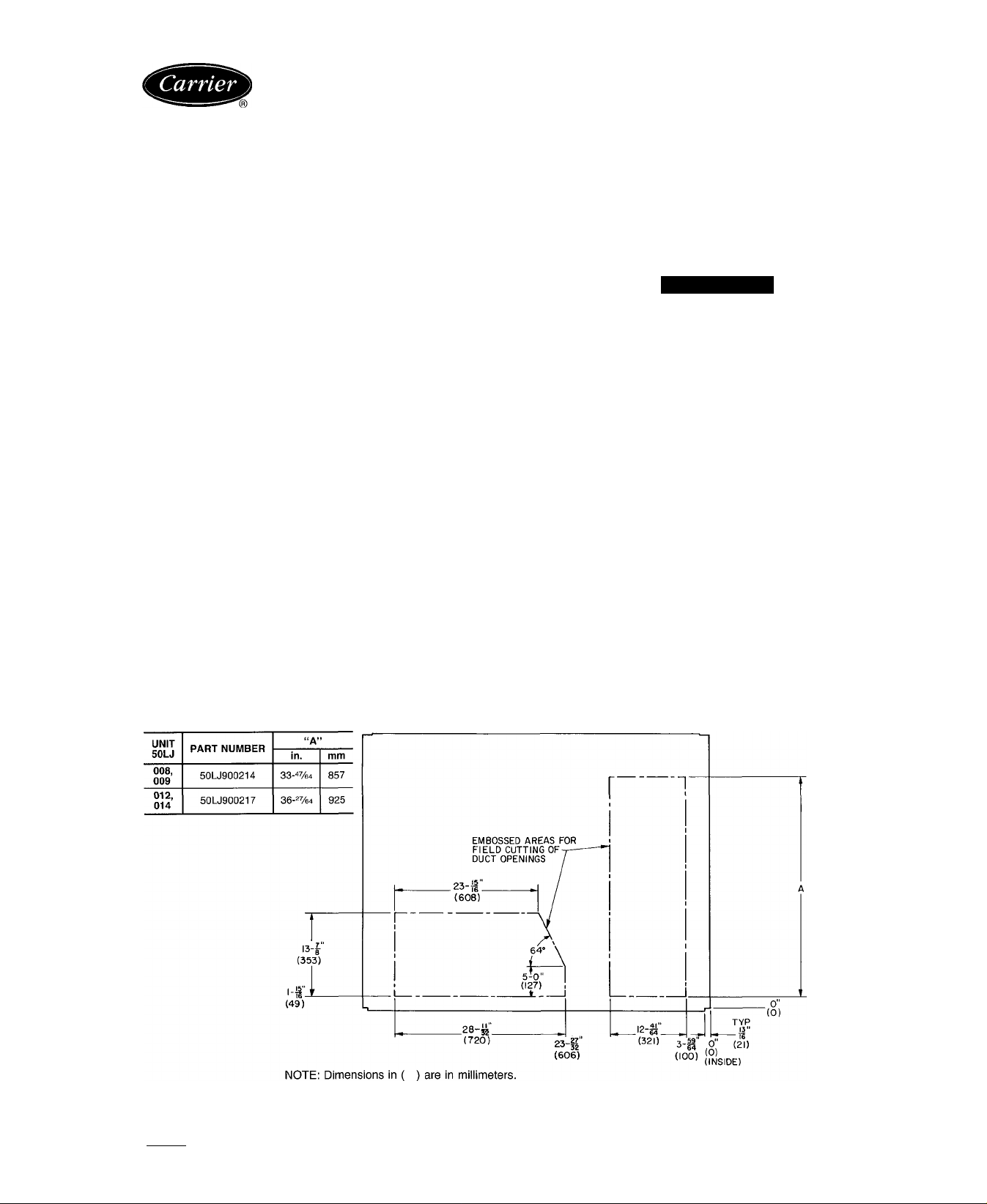
Unit is shipped in the vertical discharge configuration.
To convert to horizontal discharge application, cut imprint
area from front panels using sheet metal cutters. See Fig. 1
Duct openings in basepan must be covered by panels pro
vided in the Accessory Duct Cover Package, part no.
50LJ900214 (50LJ008,009) or 50LJ900217 (50LJ012,014).
Using screws provided in accessory package, install cov
ers on duct openings in basepan of unit with insulation-side
down. Seals around opening must be tight.
SAFETY CONSIDERATIONS
Installation and servicing air conditioning equipment can
be hazardous due to system pressure and electrical compo
nents. Only trained and qualified service personnel should
install, repair or service air conditioning equipment.
Untrained personnel can perform basic maintenance func
tions of cleaning coils and filters and replacing filters. All
other operations should be performed by trained service per
sonnel. When working on air conditioning equipment, ob
serve precautions in the literature, tags and labels attached
to the unit, and other safety precautions that may apply
IMPORTANT: An external filter kit MUST be used
or the filters MUST be field-installed outside the unit
on horizontal applications with accessory economizer
or two-position damper. Otherwise, the economizer
or two-position damper must be partially removed to
access the filters. The area of the field-installed fil
ters should be equal to the area of the factoryinstalled filters.
1-15"
' 16
(49)
Fig. 1 — Horizontal Conversion Imprint Dimensions
Manufacturer reserves the right to discontinue, or change at any time, specifications or designs without notice and without incurring obiigations.
Book|1 |4 PC 111 Catalog No 565-004 Printed in U S A Form 50LJ-4SI Pg 1 11-91 Replaces: 50LJ-2SI
Tab 1b 6b
Page 2
Step 1 — Provide Unit Support
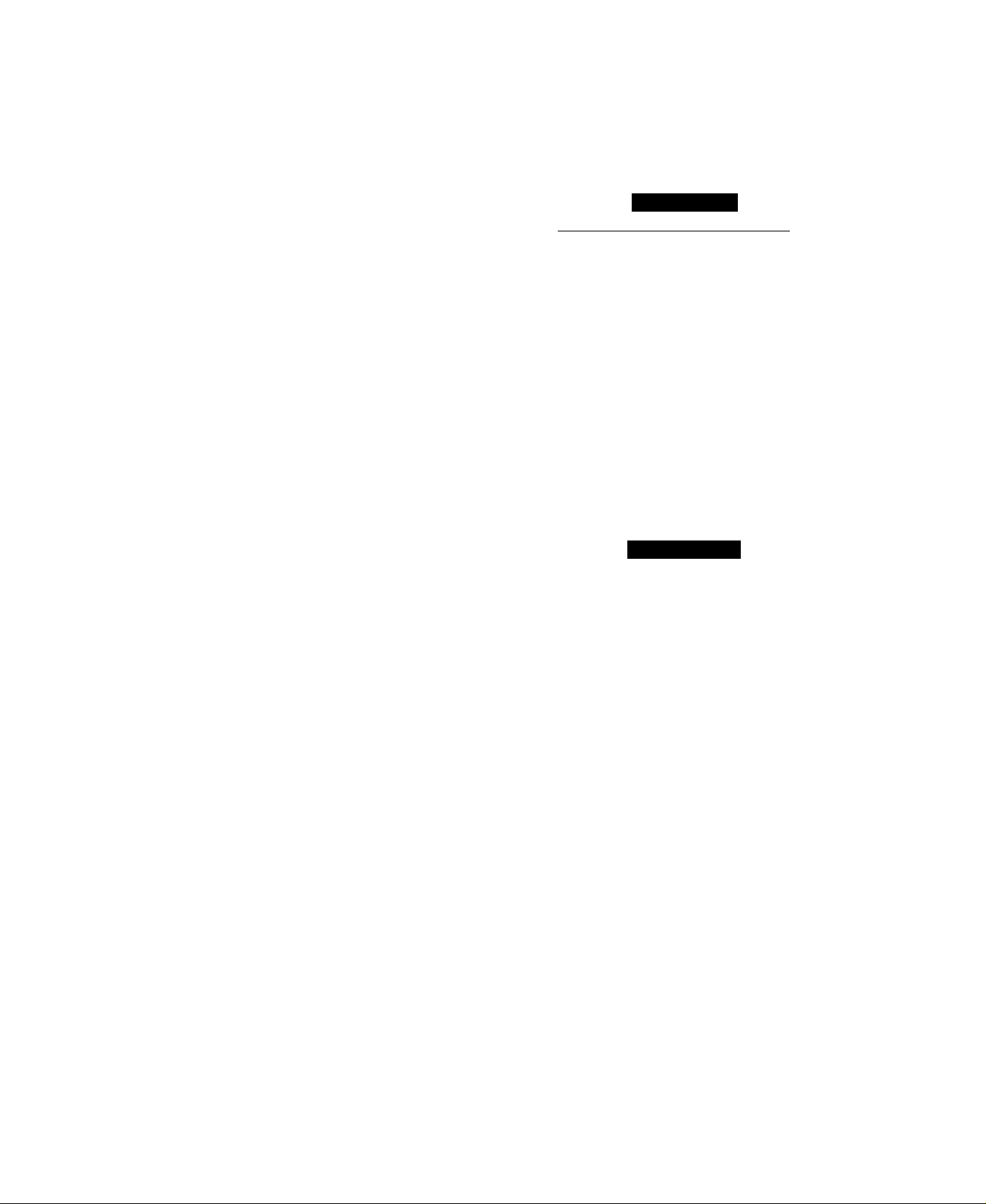
ROOF CURB — Assemble and install accessory roof curb
in accordance with instructions shipped with curb. See
Fig. 2. Install insulation, cant strips, roofing and counter
flashing as shown. Ductwork must be attached to curb, not
to unit. If electric or control power is to be routed through
the curb, attach the accessory thru~the-curb service connec
tion plates to the roof curb in accordance with the accessory
installation instructions. Connection plates must be in
stalled before unit is set on roof curb.
IMPORTANT: The gasketing of the unit to the roof
curb is critical for water integrity. Install gasket sup
plied with the roof curb as shown in Fig. 2. Improp
erly applied gasket can also result in air leaks and
poor unit performance.
Curb should be level. This is necessary for unit drain to
function properly. Unit leveling tolerances are shown in
Fig. 3. Refer to Accessory Roof Curb Installation Instruc
tions for additional information as required.
SLAB MOUNT (Horizontal Units Only) — Provide a level
concrete slab that extends a minimum of 6 in. beyond unit
cabinet. Install a gravel apron in front of outdoor-coil air
inlet to prevent grass and foliage from obstructing airflow.
NOTE: Horizontal units may be installed on a roof curb if
required.
are not required i.^’ top crpting is left on unit. Rollers may be
used to move unit across a roof. Level by using unit frame
as a reference. See Table 1 and Fig 5 for additional infor
mation. Operating weight is shown in Table 1 and Fig. 5.
Lifting holes are provided in base rails as shown in Fig.
5 and 6. Refer to rigging instructions on unit.
A CAUTION
I
______
All panels must be in place when rigging.
POSITIONING — Maintain clearance around and above
unit to provide proper airflow and service access. See
Fig. 6
Position unit on roof curb so that the following clear
ances are maintained: ‘A-in. clearance between roof curb
and base rails on each side and front of unit; U/32-in. clear
ance between roof curb and rear of unit (see Fig. 2, section
C-C).
Do not install unit in an indoor location. Do not locate
unit air inlet near exhaust vents or other sources of contam
inated air.
Although unit is weatherproof, guard against water from
higher level runoff and overhangs.
After unit is in position, remove polyethylene shipping
wrapper and rigging skid.
_________
|
Step 2 — Field Fabricate Ductwork — On verti
cal discharge units, secure all ducts to roof curb and build
ing structure. Do not connect ductwork to unit. For hori
zontal applications, field-supplied flanges should be attached
to horizontal discharge openings and all ductwork attached
to the flanges. Insulate and weatherproof all external duct
work, joints and roof openings with counter flashing and
mastic in accordance with applicable codes.
Ducts passing through an unconditioned space must be
insulated and covered with a vapor barrier.
If plenum return is used on a vertical unit, the return should
be ducted through the roof deck to comply with applicable
fire codes.
A minimum clearance to combustibles is not required around
ductwork on vertical discharge units. On horizontal dis
charge units, a minimum clearance of one in. is required
for the first 12 in. of ductwork. Cabinet return-air static
shall not exceed —.35 in. wg with economizer or —.45 in.
wg without economizer
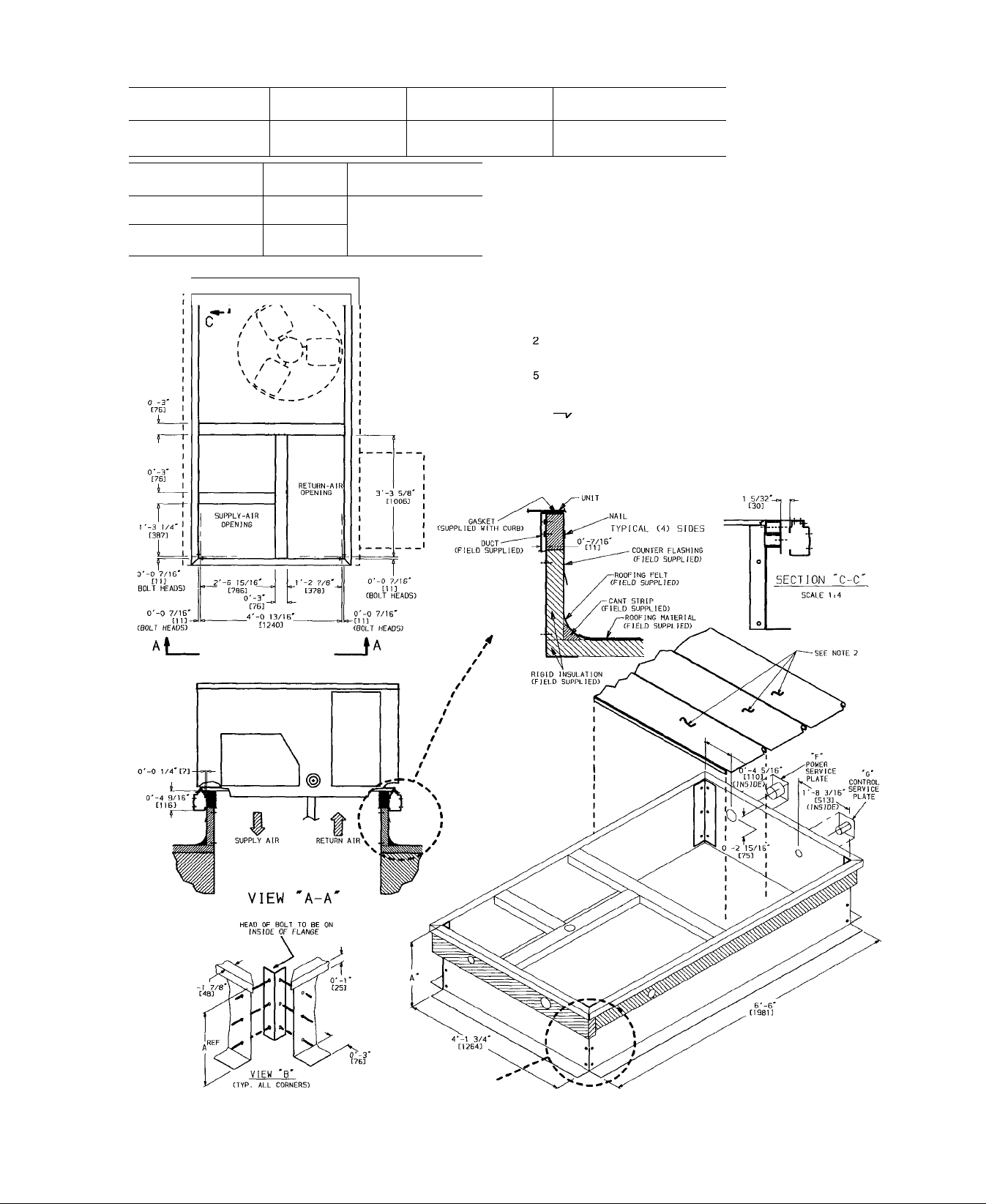
Step 3 — Install External Trap for Condensate
Drain — All units must have an external trap added. A
y4-in. NPT connection is located on the side of the unit.
Use a trap at least 4-in. deep, and protect against freeze-up.
See Fig. 4.
If drain line is run to a drain, pitch line away from unit at
one in. per 10 ft of run. Do not use a pipe size smaller than
the unit connection.
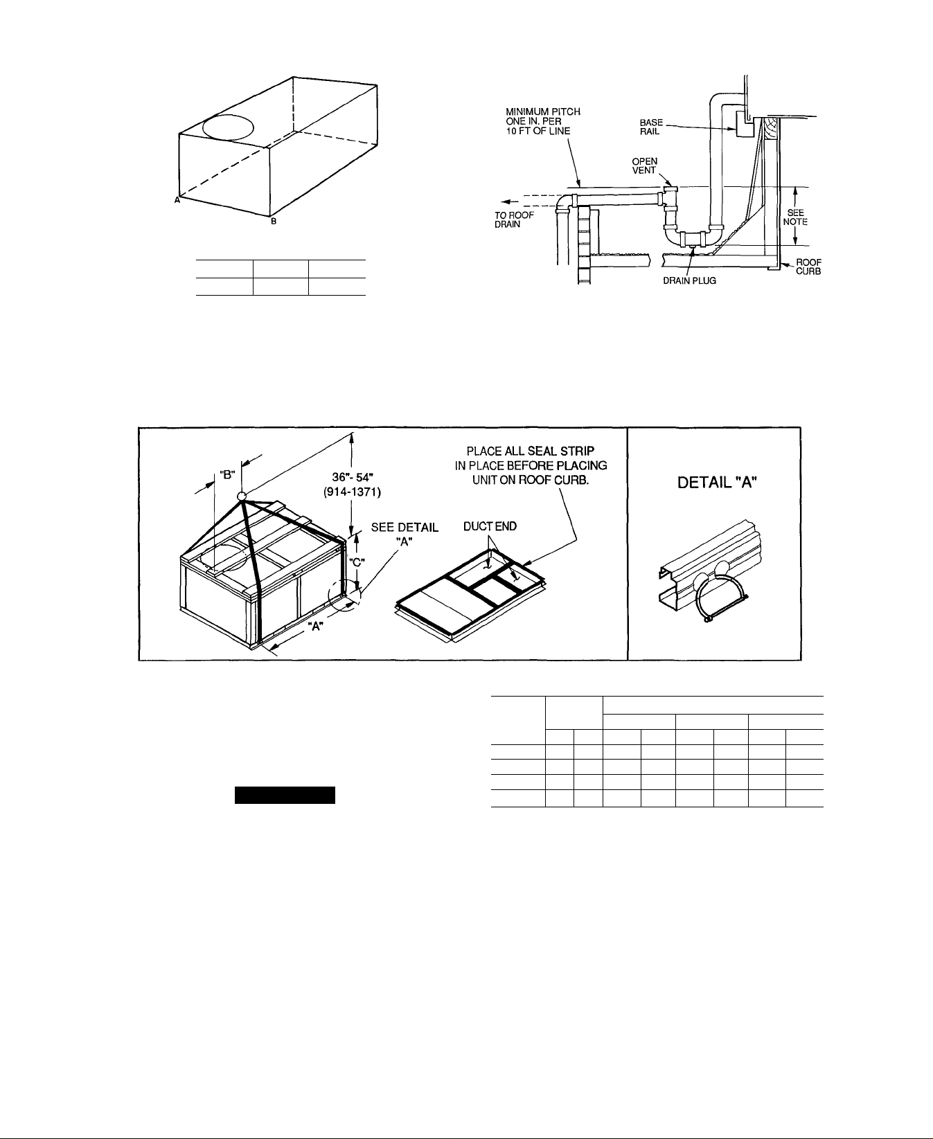
Step 4 — Rig and Place Unit — inspect unit for
transportation damage. File any claim with transportation
agency. Keep unit upright and do not drop. Spreader bars
Step 5 — Make Electrical Connections
A WARNING
Unit cabinet must have an uninterrupted, unbroken elec
trical ground to minimize the possibility of personal in
jury if an electrical fault should occur. This ground may
consist of electrical wire connected to unit ground lug
in control compartment, or conduit approved for elec
trical ground when installed in accordance with NEC
(National Electrical Code) ANSI (American National
Standards Institute) /NFPA (National Fire Protection As
sociation) 70-1987 and local electrical codes. Failure
to follow this warning could result in the installer be
ing liable for personal injury of others.
FIELD POWER SUPPLY - All units except 208/230-v
units are factory wired for the voltage shown on the name
plate. If the 208/230-v unit is to be connected to a 208-v
power supply, the transformer must be rewired by moving
the black wire from the 230-v red wire on the transformer
and connecting it to the 200-v blue wire from the trans
former. The end of the red wire then must be insulated.
Refer to unit label diagram for additional information.
Pigtails are provided for field wire connections. Use factory-
supplied splices or UL (Underwriters’ Laboratories) ap
proved copper/aluminum connector.
When installing units, provide a disconnect per NEC.
All field wiring must comply with NEC and local require
ments. In Canada, electrical connections must be in accor
dance with CSA (Canadian Standards Association) C22.1
Canadian Electrical Code Part One.
t
Page 3
UNIT SIZE
50LJ008, 009,
012 & 014
“F” POWER
1" [25] NPT or
2" [51] NPT
SERVICE PLATE SIZES
“G” CONTROL
%" [19] NPT
CONNECTOR PKG.
ACY.
50DJ901311
ROOF CURB
ACCESSORY
50DJ901371
50DJ901381
- - - -1- -
V----------------
“A” UNIT SIZE
1'-2"
[356]
2'-0"
50LJ008, 009,
012 & 014
[610]
NOTES:
1. Roof curb accessory is shipped unassembled.
Insulated panels.
3. Dimensions in [ ] are in millimeters.
4. Roof curb, galvanized steel.
Attach ductwork to curb (flanges of duct rest on curb ).
6. Service clearance 4 ft on each side.
7. Direction of airflow
SEE VIEW
Fig. 2 — Roof Curb
Page 4
MAXIMUM ALLOWABLE
DIFFERENCE (in.)
A-B B-C A-C
0.5 1 0 1 0
Fig. 3 — Unit Leveling Tolerance
NOTE: Trap should be deep enough to offset maximum unit static
difference. A 4-in trap is recommended.
Fig. 4 — External Trap Condensate Drain
NOTES-
1 Dimensions in ( ) are in miiiimeters
2. Hook rigging shackles through holes in base rail, as shown in
detail “A” Holes in base rails are centered around the unit cen
ter of gravity. Use wooden top skid when rigging to prevent rig
ging straps from damaging unit
3. Unit weights do not include economizer. See Table 1 for econ
omizer weights.
A CAUTION
All panels must be in place when rigging
Fig. 5 — Rigging Details
MAX
UNIT
50LJ008 755
50LJ009 760 345 77.42
50LJ012
50LJ014
WEIGHT
lb
915
930
in.
kg
342 77 42
415 77.42
422
77.42
“A”
DIMENSIONS
mm
in. mm
1967
40 25
1967
40 25 1022 41.31
1967
40.25 1022 49.31
1967
40 25
“B” “C”
in. mm
1022 41.31 1050
1022 49.31
1050
1253
1253
t
Page 5
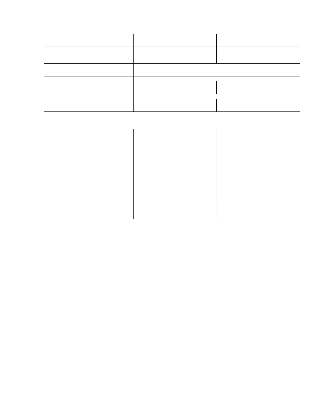
Table 1 — Physical Data
BASE UNIT 50LJ
NOMINAL CAPACITY (tons)
OPERATING WEIGHT (lb)
Unit 755
With Economizer 799
Roof Curb 143
COMPRESSOR
Quantity 2
Oil (oz) (each compressor) 55
REFRIGERANT TYPE
Operating Charge (Ib-oz)
Circuit 1 7- 0 7-0 9-7
Circuit 2 5-12
CONDENSER FAN Propeller
Qty...Diameter (in.) 1 ..26 1...26 1 . 26 1...26
Nominal Cfm
Motor Hp...Rpm % ..1100
CONDENSER COIL
Rows...Fins/in.
Total Face Area (sq ft)
Size (in.) 15 X 15
Type Drive
Nominal Cfm 3000
Maximum Continuous Bhp
Motor Frame 56
Fan Rpm Range 590-840
Motor Bearing Type
Maximum Fan Rpm
Motor Pulley Pitch Diameter A/B (in.)
Fan Pulley Pitch Diameter (in.)
Belt — Type...Length (in.) A...48
Pulley Center Line Distance (in.)
Speed Change per Full Turn of 50
Movable Pulley Flange (rpm)
Movable Pulley Maximum Full Turns 5
From Closed Position
Factory Setting — Full Turns Open 5
Factory Speed Setting (rpm) 590
Fan Shaft Diameter at Pulley (in.)
EVAPORATOR COIL
Rows...Fins/in. 3. 15
Total Face Area (sq ft)
OUTDOOR-AIR INLET SCREENS
Qty...Size (in.)
RETURN-AIR FILTERS
Qty...Slze (In.)
008
71/2
6500 6500 7000 7200
2.17
18.0
Enhanced Copper Tubes, Aluminum Lanced Fin
Belt Belt Belt
2.4
Ball
2100 2100 2100 2100
2.4/3 4
7.0
16.75-19.25
1
Enhanced Copper Tubes, Aluminum Double-Wavy Fin
80
4..16x20x2 I 4...16x20x2 | 4 20 x 20 x 2 4 20 X 20 X 2
009
8V2
760 915 930
804
143 143 143
Hermetic
2 2
55
R-22
6-2
%...1100
2. 17 I 2...17 I 2.. 17
20 5 25.0 25.0
15 X 15 15 X 15
3400 4000 5000
2.4
56
590-840 690-935 860-1080
Ball
2 4/3.4
70
A .48
16 75-19.25
50 50 44
5
5
590 690 860
1 1 1
3. .15 3 .15 4...15
80 100 11.1
Cleanable
1 20 X 25 X 1
1.. 16 X 25 X 1
Disposable
012 014
10
959
70
8-6
1100
2.4
56 56
Ball Ball
2.8/3.8 4.0/5 0
70 8.0
A...51
18.25-20 75 18.25-20 75
5 5
5 5
LEGEND
Bhp — Brake Horsepower
I2V2
974
2
70
8- 3
8-11
%...1100
15 X 15
Belt
42
A...57
Page 6
UNIT
50LJ008
50LJ009
50U012 915
50U014 930
755
760 345
STD. UNIT
WEIGHT
Lb
342
415
422
Kg
ECONOMIZER
WEIGHT
Lb
44
44
44
44
CORNER
WEIGHT (A)
Lb
Kg
164
20
165 75
20
199
20
202
20
CORNER
WEIGHT (B)
Lb
Kg
74
140
141 64
90 170
92 172 78
FILTER ACCESS PANEL
(DISPOSABLE FILTERS)
CORNER
WEIGHT (C)
Lb
208
209
252
256
Kg
94 243 110
94 245 111
114
116
Kg
64
77
NOTES:
1 Dimensions in [ ] are in millimeters
CORNER
WEIGHT (D)
Lb
Kg
294 134
300 136
“H” “J
Ft-ln.
mm Ft-ln.
2-0% 632
1-2%
378
1-2%
378
1-2% 378
mm
3-5¥i6
1050
3-5¥ie
1050
4-1 yi 6 1253
4-15/16
1253
Ft-in.
2-9"/ie
2-9”/i6
3-0%
3-0%
“K”
mm
856
856
924
924
Center of gravity
3 Direction of airflow
4 On vertical discharge units, ductwork to be attached to accessory roof curb
only For horizontal discharge units, field-supplied flanges should be aftached fo horizontal discharge openings and all ductwork should be at
tached to the flanges.
5 Minimum clearance (local codes or jurisdiction may prevail):
a Bottom to combustible surfaces (when not using curb) zero in on ver
tical discharge units, and one in on horizontal discharge units,
b. Condenser coil, for proper airflow, 36 in. one side, 12 in. the other The
side getting the greater clearance is optional
c Overhead, 60 in to assure proper condenser fan operation
d Horizontal supply and return end, zero inches,
e Between units, control box side, 42 in per NEC
f Between unit and ungrounded surfaces, control box side, 36 in. per NEC
g Between unit and block or concrete walls and other grounded surfaces,
control box side, 42 in per NEC
6 With the exception of the clearance for the condenser coil as stated in Notes
5b and c, a removable fence or barricade requires no clearance
7 Units may be installed on combustible floors made from wood or class A,
B, or C roof covering material.
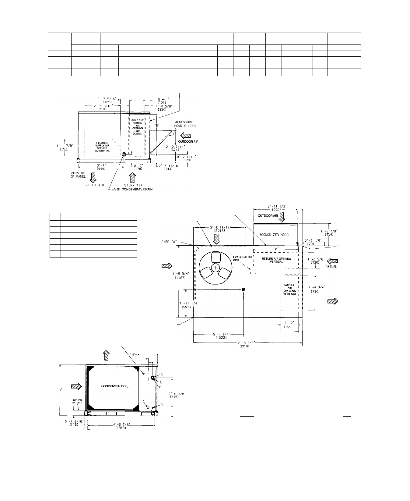
RIGHT SIDE
CONNECTION SIZES
1%" dia [35] field power supply hole
A
2y2” dia [64] power supply knockout
B
1%" dia [44] charging-port hole
C
%" dia [22] field control wiring hole
D
%”-14 NPT condensate drain
E
2" dia [51] power supply knockout
F
ELECTRICAL
DISCONNECT LOCATION
LEFT SIDE
0'-7 3/8
■ [187]
- 0 -3 13/16'
FILTER/ECONOMIZER ACCESS PANEL
CONDENSER COIL
[97]
REAR
FRONT
0'-3 9/16'
C90J
,__, 0 -5 1/2
] i_ [140]
SUPPLY AIR
"L 0'-5 7/16'
\H38]
0'-3 1/8' ^CORNER 'C'
[79]
O'-O 3/8'
[10]
AIR
r
0'-2 9/16^
[65] TYP
LEFT SIDE
ÍB©©
0'-5 3/4'
[146]
Fig. 6 - Base Unit Dimensions
CONTROL BOX AND
COMPRESSOR ACCESS PANEL
EVAPORATOR-FAN MOTOR,
BLOWER AND ELECTRIC
HEAT ACCESS PANEL
FORK LIFT SLOTS
FRONT
©B
0'-2 1/4' [57]
(TYP 8 PLACES)
t
Page 7

Install conduit through side panel openings. Install con
duit between disconnect and control box. Install power lines
to terminal connections as shown in Fig. 7.
Voltage to compressor terminals during operation must
be within voltage range indicated on unit nameplate (see
Table 2). On 3-phase units, voltages between phases must
be balanced within 2% and the current within 10%. Use the
formula shown in Table 2, Note 2 to determine the % volt
age imbalance. Operation on improper line voltage or ex
cessive phase imbalance constitutes abuse and may cause
damage to electrical components. Such operation would in
validate any applicable Carrier warranty.
FIELD CONTROL WIRING — Install a Carrier-approved
accessory thermostat assembly according to installation in
structions included with the accessory. Locate thermostat
assembly on a solid wall in the conditioned space to sense
average temperature in accordance with thermostat instal
lation instructions.
Route thermostat cable or equivalent single leads of col
ored wire from subbase terminals to low-voltage connec
tions on unit (shown in Fig. 8) as described in Steps 1-4
below.
NOTE; For wire runs up to 50 ft, use no. 18 AWG (Amer
ican Wire Gage) insulated wire (35 C minimum). For 50 to
75 ft, use no. 16 AWG insulated wire (35 C minimum).
For over 75 ft, use no. 14 AWG insulated wire (35 C min
imum). All wire larger than no. 18 AWG cannot be directly
connected to the thermostat and will require a junction box
and splice at the thermostat.
1. If unit is mounted on roof curb and accessory thru-thecurb service plate connection is used, route wire through
connection plate.
2. Pass control wires through the hole provided on unit (see
connection D, Connection Sizes Table, Fig. 6).
3. Feed wire through the raceway built into the corner post
to the 24-v barrier located on the left side of the control
box. See Fig. 9. The raceway provides the UL-required
clearance between the high- and low-voltage wiring
4. Connect thermostat wires to screw terminals of lowvoltage connector.
HEAT ANTICIPATOR SETTINGS - Set heat anticipator
settings as shown in Table 3.
#
50LJ008-014. 575-3-60
LEGEND
C
COMP(S)
IFC
NEC
TB
Contactor
Compressor(s)
Indoor (Evaporator) Fan Contactor
National Electrical Code
Terminal Block
Terminal Block Connection
Splice Connection
Field Wiring
Factory Wiring
BLK
YEL I
<g>
^ <i>
DISCONNECT
PER NEC
I BLU
I 1
' !
' 1
' '
50LJ014, 208/230-3-60
TO COMPS
'v'
TB2 I
--
1
50LJ008-012, 208/230-3-60; 50LJ008-014.460-3-60
DISCONNECT
PER NEC
Fig. 7 — Power Wiring Connections
BLK
YEL I
<£>
<§)
FIELD POWER SUPPLY
! DÌSCONNÌCT I
I
___
ft
' ! 1
' '
' 1
1 1
___________
TO COMPS
BLU
<§>
I
Page 8

Table 2 — Electrical Data
UNIT
SOLJ
008
(7% Tons)
009
(81/2 Tons)
012
(10 Tons)
014
(121/2 Tons)
NOMINAL
VOLTAGE
(60 Hz)
208/230
(3-phase)
460
(3-phase)
575
(3-phase)
208/230
(3 phase)
460
(3-phase)
575
(3-phase)
208/230
(3-phase)
460
(3-phase)
575
(3-phase)
208/230
(3-phase)
460
(3-phase)
575
(3-phase)
VOLTAGE
RANGE
Max
Min
187
414 508
518 632 49
187 254 162
414
518 632 61
187 254
414 508
518
187 254
414
518 632
COMPR
(each)
RLA
254
13.7 82 3.0 5 8
6.9 41
OFM IFM
LRA FLA FLA
1 5 26
30 1 5 2.6
84 30 5.8
508 8.0 42 1 5 26
33 1 5
26
192 105 30 58
55 1 5 26
96
632
22 3
508
45
83
137
1.5 26
30 120
104 69 1 5 54
96 55 1 5
54
ELECTRIC HEAT*
Nominal
kW**
7.8/10 4
12 0/16 0
18 6/24 8
24.0/32 0
31.8/42 2
13.9
165
27 8
33 0
41.7
180
36 0
7 8/10 4
12 0/16 0
18 6/24 8
24 0/32 0
31 8/42.4
139
16.5
27.8
33.0
41.7
180
36 0
7 8/10 4
12.0/16 0
24 0/32.0
31 8/42 4
37.5/50 0
165
27 8
33 0
41 7
50.0
18.0
36.0
54 0
7 8/10.4
12.0/16.0
24 0/32.0
31 8/42 4
37 5/50 0
165
27 8
33 0
41 7
50 0
180
36 0
54 0
LEGEND
FLA
HACR
IFM
LRA
MCA
MOCP
OFM
RLA
‘Heaters are field installed only.
fUsed to determine minimum disconnect size per NEC
“Heater capacity (kW) Is based on heater voltage of 240 v, 480 v or 575 v If power
distribution voltage to unit varies from rated heater voltage, heater kW will vary
accordingly
ttFuse or HACR circuit breaker
([Fusing in single point box provides the required branch circuit protection
NOTES;
1 In compliance with NEC requirements for multimotor and combination load equip
2 Unbalanced 3-Phase Supply Voltage
Full Load Amphull Load Allies
Heating, Air Conditioning and Refrigeration
Indoor (Evaporator) Fan Motor
Locked Rotor Amps
Minimum Circuit Amps
Maximum Overcurrent Protection
Outdoor (Condenser) Fan Motor
Rated Load Amps
ment (refer to NEC Articles 430 and 440), the overcurrent protective device for
the unit shall be fuse or HACR breaker The CSA units may be fuse or circuit
breaker
N e v e r o p e r a t e a m ot o r w h e r e a p h a s e im b a lan ce in sup p ly volt a g e is g rea ter
than 2% Use the following formula to determine the % voltage imbalance
% Voltage imbalance
= 100 x
max voltage deviation from average voltage
average voltage
POWER SUPPLY DISCONNECT SIZEt
= 457
42/ 42
42/ 42
45/ 50
66/ 75
83/ 92
108/124
47/ 47
47/ 47
47/ 50
66/ 75
83/ 92
108/124
108/124
127/145
115/131
134/152
3
FLA
21
22
26
38
46
58
16
23
42
23
23
26
38
46
58
19
23
42
54/ 54
54/ 54
54/ 54
83/ 92
27
27
41
46
58
69
24
24
42
59
69/ 69
69/ 69
69/ 69
91/102
32
32
45
52
64
75
30
30
45
65
LRA
223/223
112
90
227/227
114
96
269/269
140
120
376/376
189
161
FLA MCA
21 7/ 25 0
33 4/ 38 1
51 7/ 59 7
66 7/ 74 2
88 4/102.0
167
19.8
33 4
39 7
50 2
170
34.0
21.7/ 25 0
33 4/ 38 1
51 7/ 59 7
66 7/ 74.2
88 4/102.0
16.7
19.8
33 4
39 7
50 2
170
34.0
21 7/ 25 0
33 4/ 38 1
66 7/ 74 2
88 4/102 0
104 1/120 2
198
33 4
39 7
50.2
60 1
170
34 0
51 0
21 7/ 25 0
33 4/ 38 5
66 7/ 77 0
88 4/102 0
104 2/120 3
198
33 4
39 7
50 2
60 1
170
34 0
51 0
Example: Supply voltage is 460-3-60
Determine maximum deviation from average voltage
(AB) 457 - 452 = 5 V
(BC) 464 - 457 = 7 V
(AC) 457 - 455 = 2 V
Maximum deviation is 7 v
Determine % voltage imbalance
% Voltage imbalance = 100 x — = 1 53%
^ 457
This amount of phase Imbalance is satisfactory as it Is below the maximum al
lowable 2%
IMPORTANT: If the supply voltage phase imbalance is more than 2%, contact
your local electric utility company immediately
39 7/ 39 7
39 7/ 39 7
48 9/ 54 9
71 9/ 81 8
90 6/100 0
117 7/134 8
196
24 1
28 1
45 0
52 9
65 9
15 1
24 5
45 7
45 4/ 45.4
45 4/ 45.4
48 9/ 54 9
71 9/ 81 8
90.6/100 0
117.7/134 8
22 1
24 1
28 1
45 0
52 9
65 9
178
24 5
45 7
52 1/ 52 1
52.1/ 52 1
52.1/ 54 9
90.6/100 0
117 7/134 8
137.4/127 4
25.7
28.1
45 0
52 9
65 9
63 4
22 8
24 5
45 7
67 0
65 3/ 65 3
65 3/ 65 3
65 3/ 65 3
98 4/111 2
125 5/142 5
145 3/135 3
30 3
31 6
48 5
56 4
69 4
66 9
28 5
28 5
49 2
70 5
AB = 452 V
BC = 464 V
AC = 455 V
Average Voltage = •
MOCPtt
45/ 45
45/ 45
50/ 60
80/ 90||
100/10011
125/15011
50/ 50
50/ 50
50/ 60
80/ 9011
100/10011
125/15011
60/ 60
60/ 60
60/ 60
100/100
125/150
150/150
80/ soil
80/ 8011
80/ 8011
100/12511
150/15011
150/15011
7
7011
7011
7011
7011
7011
25
25
30
50
60
20
25
50
25
25
30
50
60
20
25
50
30
30
50
60
30
30
50
35
35
50
60
70«
80«
35
35
50
80«
452 + 464 455
1371
3
i
Page 9

Table 3 — Heat Anticipator Settings
208/230 460
UNIT
Heater kW 1 Stage 2 Stage Heater kW 1 Stage
104, 160 03
32 0, 24 8 06 0.3 03
50LJ
42 4, 50 0 0 9 06
Configuration
Stage 1 Stage 1
NA NA
Stage 2 Stage 1
139, 165
27 8, 33 0
03
41 7, 50 0 06 03 03
UNIT VOLTAGE
Configuration
Stage 1
03
NA NA
2 Stage
Stage 2
575
Configuration
Heater kW 1 Stage 2 Stage
Stage 1 Stage 1 Stage 2
18 0, 36 0 0.3 NA NA
54.0 0.6 03 03
THERMOSTAT CONNECTIONS
BAT - Battery
C — Contactor
DAT — Discharge-Air Thermistor
EWIC/EMFC — Energy Management Closed
EMO/EMFO — Energy Management Open
EQUIP — Equipment
GND — Ground
IFC — Indoor-Fan Contactor
THERMOSTAT
THREE-PHASE
POWER SUPPLY
LEGEND
IFR — Indoor-Fan Relay
OFC — Outdoor (Condenser) Fan Contactor
P — Plug
TB — Terminal Block
TRAN — Transformer
----------
Field Wiring
Factory Wiring
Fig. 8 — Control Wiring Connections
RACEWAY-
HOLE IN
END PANE!
(HIDDEN)
Fig. 9 — Field Control Wiring Raceway
Step 6 — Adjust Evaporator-Fan Speed — Adjust
evaporator-fan speed to meet jobsite conditions.
For units with electric heating, required minimum cfm is
2250 for 50LJ008; 2550 for 50LJ009; and 3000 for 50LJ012
and 014 with the following exceptions.
UNIT
50LJ012
and 014
50LJ008-
014
UNIT
VOLTAGE
208/230
208/230 50.0 Horizontal 3200
460
575
HEATER
kW
42 4
50.0
180
36 0
UNIT
CONFIG-
ATION
Horizontal 3200
Horizontal
or
Vertical
Horizontal
or
Vertical
REQUIRED
MINIMUM
CFM
3200
2800
2350
Table 4 shows fan rpm motor pulley settings, Table 5
shows motor efficiencies and Table 6 gives accessory static
pressure drops. Refer to Tables 7-12 to determine fan speed
settings. Fan motor pulleys are factory set for speed shown
in Table 1.
Page 10

008,
009
012 935
014
1080 1060 1035 1015 990 970 950 930 905
Table 4 — Fan Rpm at Motor Pulley Settings
MOTOR PULLEY TURNS OPEN
0 V2 1 IV2 2 2V2 3 3V2 4 4V2 5
840 815 790
910 890 865
765 740 715 690 665
840 815 790 765
640
740
615 590
715
885 860
Table 5 — Evaporator-Fan Motor Efficiency
MOTOR
50LJ008-012 83
50LJ014
NOTE: Convert bhp to ’
„ 746 X Bhp
Watts =-^——^77T^-----
Motor Efficiency
EFFICIENCY (%)
85
690
f
Table 6 — Accessory Static Pressure Drop (in. wg) 50LJ008-014
COMPONENT
1 Heater Module 020 030 .050 .065 .080 .100 120 140
2 Heater Modules .030 .050
Economizer
2200 2500
.020 .020 030 040 .050 060 .070 .080
3000 3500
070 .090
CFM
4000
4500 5000
.120 140
.160
5500 6000
190
.155
210
090
I
10
Page 11

Table 7 — Fan Performance, 50LJ008,009 — Vertical Discharge Units
LEGEND
— Brake Horsepower
Bhp
NOTES:
1. Boldface indicates field-supplied drive required
2 indicates field-suppiied motor and drive required.
3 Maximum usabie bhp is 2.4. Extensive motor and electrical test
ing on the Weathermaker® I units ensures that the full horse
power range of the motor can be utilized with confidence Using
Table 8 — Fan Performance, 50LJ012 - Vertical Discharge Units
IRFLOW
(Cfm)
3000
3100
3200
3300
3400
3500 596
3600 609
3700
3800
3900
4000
4100
4200
4300
4400 715
4500 729 1.83
4600 742 1.94
4700
4800
4900 783
5000
0.2
Rpm Bhp
532
544
557
570
583
622 1.09 686
635
649
662
675 1.42
689 1.52
702 1.61 759 1.88
756 2 06 810
770 2 18
mm
0.64 605 0.81 670
0.70 616 0.86 680
0.75 628
0.81 639 0.99 700 1 18
0.88
0.94 663 1.14 721
1.01
1.16 698 1 39
1.25 710 1 48
1.33 722
1 72
2.31 mm
0.4
Rpm Bhp Rpm Bhp Rpm Bhp Rpm Bhp Rpm
0.93
1.06
651
0.6
0.97
1.03
690 1 10 746 1.28 796
711
1 25 767 1 44 815 1 61
1.33
674 1.22 732 1 42 787 1.61 836
1.30 744
1.57
1.67
734
746 1 77
1 50
755
1.59 808 1.80
767
1.68 818 1 90
778 1 78 829 2.01 878
790
1.89
1 99 851
801
813 2 11
772
1.99 825 2.22
785 2 10
797 2.22
837
mm
2.35
ms
2.34
mm
iiaas:
mm
LEGEND
Bhp — Brake Horsepower
NOTES:
1 Boldface indicates field-supplied drive required
2. indicates field-supplied motor and drive required
3. Maximum usable bhp is 2.4. Extensive motor and electrical test
ing on the Weathermaker I units ensures that the full horsepower
EXTERNAL STATIC PRESSURE (in. wg)
0.8
725 1.12 778 1 28
735 1 20
757
1.36 805
711 1.52 826
797
1.70
839 2.12
2 23
862 2.34
mM
S8& 029
89© a.72:
ms
SM
your fan motors up to the horsepower ratings shown will not re
sult in nuisance tripping or premature motor failure. Unit warranty
wiil not be affected
Use of field-supplied motor may affect wire sizing Contact your
Carrier representative to verify
Values include losses for filters, unit casing and wet coils.
Motor drive range is 590 to 840 rpm. All other rpms require a
field-supplied drive
1.2
Bhp
825
1.43
835 1 52
787
1.0
1.36
1.44 844 1 61
1.52 854
1.71
1.80
1.70
863
1.79
871 1 88
880 1 98
847 1 91 890 2.09
857 2.01 901 2 20
867 2.11
912 2.32
2 22
888 2.33
mm
■Z.SS:1
90©
0S®|3
2.7?,
STSSl.
S40
iysei
as'i
— —
~
-
range of the motor can be utilized with confidence. Using your
fan motors up to the horsepower ratings shown will not result in
nuisance tripping or premature motor failure Unit warranty will
not be affected.
Use of field-supplied motor may affect wire sizing. Contact your
Carrier representative to verify.
Values include losses for filters, unit casing and wet coils
Motor drive range is 690 to 935 rpm. All other rpms require a
field-supplied drive.
1012J 2.36
—
11
Page 12

Table 9 — Fan Performance, 50LJ014 — Vertical Discharge Units
AIRFLOW
(Cfm)
3700
3800 668
3900 683
4000
4100
4200 726
4300 741
4400
4500
4600
4700
4800
4900 829
5000
5100
5200
5300 888
5400
5500
5600
5700
5800
5900
6000
6100
6200 .4^eз
6300
Rpm
654 1.12
697
711
755
770 1.89
784 2.00
799 2.13
814 2.25 863
843
858
873
903 3.13 949
918
933
948
963
978 4.00
■m&i
iGáaí f4m
0.2
Bhp
1.20
1.28
1.37
1.46
1.56
1.66 794 1.91
1.77 808 2.03
0.4
Rpm Bhp Rpm Bhp Rpm ^Bhp Rpm
714
1.31 767 1.50 815
727
1.40
741
1.49 793
754
1.59 806
767
1.69
780
1.80
821 2.15
835 2.27
849 2.40
2 53 910
877 2.67 923 2.92 967
2.39
2.52 892 2.81
2.67 906 2 95 950
2.82
920
3.10
2 97 934 3 26
3 43 991 3 75
3.30 963 3.59
3 47 978
3.65 992
3.83 1006
3 77
3.95
4.14
43ÍJ
AS«!
V&7S-'
1830
ÍÍ«S
Am"
«m i-ñ7
0.6
780 1.60 827
1.70 839 1.88 884 2 05
1.80
1.90
819
832 2.01 877
845 2.12
858
2.24
871 2.37
884
2 49 928
897
2.63
2.77 954 3.02
937
3.08
3 24
963
3.40
977
3.57
1004
3.92
4.11
1018
‘ms'
4,SSi
4.88 ;s>£S3.
554’
EXTERNAL STATIC PRESSURE (in. wg)
0.8 1.0
851
864
889
902 2.48
915 2.61 955
941 2.88 981 3.11
980 3 32
993
1006 3.65
1019 3.82
1032 4 00
1045 4.18
W
iiiSSi
LEGEND
Bhp
NOTES:
1
Brake Horsepower
Boldface indicates field-supplied drive required
indicates field-supplied motor and drive required.
Maximum usable bhp is 4.2. Extensive motor and electrical test
ing on the Weathermaker® I units ensures that the full horse
power range of the motor can be utilized with confidence Using
Bhp Rpm
1.67 861 1 85
1.77
1.99
2.10
2 22
^35 931
1.95 916 2 18
873
2.16 938 2 38
895
907 2.28
2 41
919
2.54 971 2 72 1011
2 68
943
2 82
2.75
3.17
2.96
968
3.27 1030 3 48
993
1006 3.43
3 60
1019
3.48 1032 3.76
3 93 1081 4.19
1045
4.11
1058
mmi
IS
42»
tm mm
1.2
Bhp Rpm Bhp Rpm
906
2.08
927
2.28
949 2 49
960 2.60
983 2.86
995
3 01
1006
3 17
1018 3.32
1.4 1.6 1.8
Bhp Rpm
2.27 991 2.47 1030 2 65
950
959 2.38
969
979
989
1000
1022 3.10
1001 2 58 1040 2.78
2,50 1010
2.70 1049 2 91
2 62 1020 2.83
2.74
2.86
2 97
2.96
1029
3 10
1039
1049 3.23
3 37 1097
1059
1033 3.23 1070 3 51
1044 3.37
1056
3 52
3.64 1117
1081
1092 3.78
Bhp
1059 3.04
1068
3 18 1105
1077
3 31 1114
1087
3.46
3.61
1107
3.76
3.92
1127 4.07
2.0
Rpm
1064
1075
1085
1095
1124
1133
1143
1152
¥«SS3i
1067 3.69 1103 3.93
3.87 1114
4 00 mm
pM
1079
4.05
T4m
ptm
BM
■i&m
1043 3.65
1055 3.82 1091
1068
Wm
IS
— —
_
your fan motors up to the horsepower ratings shown will not re
sult in nuisance tripping or premature motor failure. Unit warranty
will not be affected.
Use of field-supplied motor may affect wire sizing. Contact your
Carrier representative to verify
Values include losses for filters, unit casing and wet coils
Motor drive range is 860 to 1080 rpm All other rpms require a
— — ~ — — — — —
—
—
—
— —
WM-
PÜPS
mm.
—
—
—
4.09
ÉM
— — — — —
— — — —
—
wM
mm
PM
Wi
mm
— — — —
—
MM
— —
w;
ÍÍÍ2S7::
mM
field-supplied drive
Bhp
2 82
2,96
3.11
3.25
3.39
3.54
3.69
3.84
4.00
4.17
_
_
#
12
Page 13

Table 10 — Fan Performance, 50LJ008,009 — Horizontal Discharge Units
AIRFLOW
(Cfm)
2200 459 0.42
2250
2300
2400
2500
2550 501
2600
2700
2800 533
2900
3000 559
3100
3200 585
3300 598
3400 610
3500 623 1 17
3600 636 1 25
3700
3750
3800
3900
4000
4100
4200
4250
4300
— Brake Horsepower
Bhp
Boldface indicates fieid-suppiied drive required.
Maximum usable bhp is 2.4. Extensive motor and eiectrical test
ing on the Weathermaker I units ensures that the fuil horse
power range of the motor can be utilized with confidence. Using
0.2
Rpm Bhp Rpm
465 0.43
471 0.45 559 0.66
482 0.50 569
494
Ò.54 581 0.76
0.57 587 0.79 659
507 0.59
520
0.65
0.71 615 0.95 683 1.20 747 1.49 802 1 75
0.77 626 1.02 693 1 27 756
546
0.83
572 0.90 648 1 17 715 1 43
0.96 660 1.24
1.03 671 1.32 739
1.10 682
649 1 33
655 1 37
661 1 41 733 1 82
674 1.49 746 1 93
1.57
687
1 66 772 2 17
699
1.75
712
1.80 792
719
1.85
725
LEGEND
indicates field-supplied motor and drive required.
0.4
Bhp Rpm
549 0.62 625 0 83 691
554 0.64 630 0 86 695
0.71 645 0 95
592
0.82 663 1.08 727
604
0.89
637
1.09
1.41
694
1.50
707
1 60
720 1.71 783
727
1 77
759 2 05
2.30
785
2.37
0.6 0.8 1.0
Bhp Rpm Bhp Rpm Bhp
635 0 89
654
1 01
1.05 722
1 14 737
672
704 1 35 765
727 1.52 785 1 83 841 2.15 ¥^35
1.62 795 1 91 851 2.26 S83
750 1.72 806
761 1.82
772
1.93
2.03 840
789
2.09
795
2.15
806
2.26
817
2.38
»46 2,’?1
,Z77SOS
asa
EXTERNAL STATIC PRESSURE (in. wg)
699
708 1 18 768 1.44
717 1.25 776 1.51
775
817 211
828 2.23
862
865
S&7 347 #;39';
soa a.16
1.2
Rpm Bhp Rpm
1 58 842
1 06 753 1.31
757 1.34 810
1.09
1.12
760 1.37
780 1 55
1.29
1.32 784 1.58 839
793 1.66 646 1.95
1.40
1.57
813 1.84
1.66
823 1.94
1.74 832 2.05 882 2.33
2 01
860 2.36 ma
2.35
: iS96i;iiaSiSi,
■3S6i|aSSl
805
1 62 850 1.91 873
1 65 859
816
824 1 72 872 2.01 909
832
1 79
836 1 83
1 87 891
855 2.04
863 2.13
872 2.22
iS^
ima
;SÉS7;
Mm
iSiSSfi
—
— — — — — — — — —
— 1 —
— —
S.i?
- 1 -
—
your fan motors up to the horsepower ratings shown will not re
sult in nuisance tripping or premature motor failure. Unit warranty
will not be affected.
Use of field-supplied motor may affect wire sizing Contact your
Carrier representative to verify.
Values include losses for filters, unit casing and wet coils
Motor drive range is 590 to 840 rpm All other rpms require a
field-supplied drive.
1.4 1.6 1.8
Bhp Rpm Bhp Rpm
1.87 857
1.94
882 2.09
887
2.13
2.17
898 2.26
2.35
906
ma
ma
ssgii
ami
mm
im
— — — — — — — —
— —
2.16 f:¥;ggli msi mesa
2.20 iiS^i
888 2.24 iiiààéfe
2.32 ami
2.40
925
iSiSSSi
iiisss;. iMS:
2SB SSr
S67 SS7 pm
ama
0m
rniinmi
ama
asm -
mi. -
' —
—
_
_ _
_ —
— — — — —
Bhp Rpm Bhp
MM
ami.
Wà MM
■2M-iàm
mè
— — —
— —
~ — —
— — —
— — —
2.0
ììskì?;
am:
572
mp
am
mm.
— —
— —
— —
— — ~ — — — — —
— — — — — — — —
— —
_ _
—
—
am-
ass
_
—
13
Page 14

Table n — Fan Performance, 50LJ012 — Horizontal Discharge Units
AIRFLOW
(Cfm)
3000
3100
3200
3300
3400
3500
3600
3700
3800
3900 582
4000 593
4100 605
4200 616
4300 628
4400 639
4500
4600 662 1.91
4700 674
4800 686
4900
5000
Rpm Bhp
484
495 0.61
505 0.66
516 0.72 589
527 0.78 599 0.93 664
537
548 0.92
560 1.00 629
571 1.08 639
651
698
mM
0.2
0.55
0.85
1.16 649
1.25 659
1.35 670
1.45 680
1.56
1.67 701 1.73 757 1.92
1.78
2.03 733
2.17
0.4 0.6 0.8 1.0 1.2
Rpm Bhp Rpm Bhp Rpm
560 0.70 631
570 0.76 638
579
0.81
0.87
609 0.99 672 1.18 731
619 1.05 680
1.12 688 1.31 747 1 51 802
1.19
1.27
1.35 717 1.56 773 1.78 823 1 98
1.44 727 1,65 781 1 86 832
1.53 737
1.63 747
690
1 84 767 2.02 817
712
1.95 777
722
0.87 690 1 03
0.92
646 0.98 708 1.16
1.05
655
1.11 724 1.30 775 1.48 827
1.24
1 39 756 1 60 810 1.81
698
1 47 764 1 69 816 1.89 865
708
1.74
1.83
2 13
2 07 787 2 24
744 2 20
797
2.36 S!®
2 31 755 2.33 80S ■.SS6 '
iW
SIS : 868 O&f. Z3&
EXTERNAL STATIC PRESSURE (in. wg)
Bhp Rpm Bhp Rpm Bhp
1,10
699
717
1.23
1,36 784
738 1.43
789 1 95 841
798 2 05
807
2.16
2.27
827
2.38
"^836
LEGEND
Bhp — Brake Horsepower
NOTES:
1. Boldface indicates field-supplied drive required
2 indicates field-supplied motor and drive required
3 Maximum usable bhp is 2 4 Extensive motor and electrical test
ing on the Weathermaker® I units ensure that the full horse
power range of the motor can be utilized with confidence. Using
747
755
1 20 800
1.27
805
1 38
1.44
761 1 34 812 1 51
767 1.40
819
1.59
1.67
794
1,56
1.64
1,75 880
833
840 1,83
1 73 847 1 92
856 2.02
2 12 908 2.32
875 2 22
883 2.32
2 08
2 18
849
88#
2.30 SQ& I
S83
Ì2.4Ì
2;02.
888 Z74
374 S34
2L7Sj
m
m
ZBT
33S zmi
003
your fan motors up to the horsepower ratings shown will not re
sult in nuisance tripping or premature motor failure Unit warranty
will not be affected
4. Use of field-supplied motor may affect wire sizing. Contact your
Carrier representative to verify.
5. Values include losses for filters, unit casing and wet coils,
6. Motor drive range is 690 to 935 rpm. All other rpms require a
field-supplied drive.
1.4
Rpm
Bhp
850
1.52
857
1 63
862
1.71
867
1 78
873
1 85
1,94 926
888
2.04
895
2.13 938
901
2.23
mM
SSi 2^
■96S- 3.11
:
3,23
[333L
m
—
1.6
Rpm
Bhp
879
1.38
896
1.66
908
1 85
915
1 98
920
2 07
2 15
931
2.23
2.33
I'M
Mm
— — — —
—
— —
Rpm
s-sssiS
—
1.8 2.0
Bhp Rpm Bhp
925
1.81 964 1.92
935
1.93 975 1.98
944
2.01
952
2.11
963
2.21
970
2.36
SitiSSSS
_
_
—
—
—
—
—
—
984
993
,1001
—
__
__
_ —
—
—
2.09
2.22
2.31
iyvsyxy
_
__
—
-
Table 12 — Fan Performance, 50LJ014 - Horizontal Discharge Units
AIRFLOW
(Cfm)
3700
3800
3900 636
4000 650
4100 665
4200 680
4300
4400 711
4500
4600
4700
4800
4900
5000
5100
5200
5300
5400 869
5500 885
5600
5700
5800
5900
6000
6100
6200
6300
0.2
Rpm Bhp Rpm
607 0.97 670 1.18
621 1.05
1.13 693
1.21 705
1.30 717 1.48 772
1.39 728
1.49 739 1.66
696
1.60 750 1.75 805
1.70 762 1.85 817
727
1.82
742
1.94 786
758
2.06 799 2.18
773
2.19 812 2.30 863
789
2.32
805
2.47 840
821
837 2.61
853 2.76 868
2 92
3 09
901 3 26
917 3 44 926 3.50
933 3.62
949 3 81
4.01 972
965
4.21’
99-7
i4AZ
1014 4,S4 Ida 4.68
0.4 0.6
Bhp Rpm Bhp Rpm Bhp Rpm Bhp
681 1.25 742 1.45 795 1.66 842
774
732 1.37
1.32 751 1.53 808 1.76 851
1.40 761
1.57
1.96 828
2.07
1.61 819
1.71 830 1.96
783 1.81 839
794
1.91 848
2.02 857
2.12 867 2.35
2.23 877 2,46 929 2 75
2.34 888 2 59 938
840
852 2.46
2.57
2.43 875 2.70 921 2 99 966 3.24
826
2.57
854 2.71 898 2 96 943 3 28
882
897 3 17 932
911 3 33
887 2 83 932
2 85 909
3 01
3 09
920 3 24 967 3.57 1009 3.86 1051
3.38
943 3.54 990 3.87
956
3.70
941 3,68 968 3 87 1013
956 3.87
4 05 4.?4-
981
4.06 995 • 4J83
’9S7
•L26 t1<308 4A2
■toos 4.46 it022
: leaa
:4.62 10S8
4.83
LEGEND
Bhp — Brake Horsepower
NOTES:
1, Boldface indicates field-supplied drive required.
2 indicates field-supplied motor and drive required.
3. Maximum usable bhp is 4 2, Extensive motor and electrical test
ing on the Weathermaker I units ensures that the full horse
EXTERNAL STATIC PRESSURE (in. wg)
0.8 1.0
782 1.56 833
1.86
2.05 883 2.25
2.14 896 2 38
2.24
899 2.72
910 2 86
3 13
955 3.42 998
978 3 72 1020
1002
4 03
4.20 Mm
ÌBS7
■4.SS
i04T
4;73- iosa 5,16
4,91 1160
TOTC
5.1-f 1112
1.2
Rpm Bhp Rpm
1.73 879
1.82 889 2.03
1.92
1.95 927 2 17 973 2.38 1013
2.12
898
861 2 02 908 2 21 950
871
917 2 32 960 2.55 1001
2.13
925 2 44 969 2 65 1009
935 2.56 979
908 2.51 945 2.68
2.63 955 2.82
919
947
957 3.11 1003
976 3 38
987
2.87
2.98
3,53
3.69
967
980
992 3 26
1005 3.16
2.96
3.11 1015
1025 3 45
3.41 1036 3.61 1073
1014
1024
1033
1042
3.56
3 71
3.84
3 98
1049
1061 3 96
1073
4.14
4 03 liSgifS-
1031 4.20
:464
iiésì?
MSSi lisa
iO/6
Mm
Mm-
4.S2
hii4 ;S,254 t-tsa:.
T125'
SiS
.iim i.5.©§
&4S
power range of the motor can be utilized with confidence. Using
your fan motors up to the horsepower ratings shown will not re
sult in nuisance tripping or premature motor failure. Unit warranty
will not be affected
Use of field-supplied motor may affect wire sizing Contact your
Carrier representative te verify.
Values include losses fer filters, unit casing and wet coils
Motor drive range is 860 to 1080 rpm All other rpms require a
.-ft 42-
-
field-supplied drive
1.4 1.6 1.8
Bhp Rpm Bhp Rpm Bhp Rpm Bhp
2.57 1046
934 2.26 980 2.48 1022 2 69
2 36 987 2.59 1030 2 81 1068 3.01
942
2.46 994
2.70
1037
2.92
2 81 1045 3.04 1085 3.27
2 92 1051 3 17 1092 3.40
2.77
988
2 89
996 3 02
3 30
3 79
4.14
1018 3.03
1028 3.14
1037
1046
1056 3 52
1064
1083 4.00
1093
Mm.
1058 3.29 1100 3.53
1066 3 41 1106 3.67
1074
3,25
3.38
3.54 1113 3.81
1084
3.66
1093 3.79 1129 4.09
3.67 1103 3.92
4.07
1112
3.83
iSMi;
MMi
MZ.
Mm MM
psaSi iiiiSSS
MM;\
MM:
534
mm
514
Mm
MM.
Mm
— ~ — — — —
— ~ — ~ — —
MM
— — —
— —
—
-
-
2.0
1058 2.87
1077
1121 3.95
SiSSE;
IW?
nS7
mm
Mèi-
Mm
Mm
Mm.
MM
— —
2 73
3.14
—
14
Page 15

#
To change fan speed;
1. Shut off unit power supply.
2. Loosen belt by loosening fan motor mounting plate nuts
(see Fig. 10).
3. Loosen movable pulley flange setscrew (see Fig 11)
4. Screw movable flange toward fixed flange to increase
speed and away from fixed flange to decrease speed. In
creasing fan speed increases load on motor. Do not ex
ceed maximum speed specified in Table 1.
5. Set movable flange at nearest key way of pulley hub and
tighten setscrew (see Table 1 for speed change for each
full turn of pulley flange).
To align fan and motor pulleys;
1. Loosen fan pulley setscrews.
2. Slide fan pulley along fan shaft
3 Make angular alignment by loosening motor from mount
ing plate.
To adjust belt tension (see Fig. 10);
1, Loosen fan motor mounting nuts.
2. Slide motor mounting plate away from fan scroll for proper
belt tension (Vi-in. deflection with one finger) and tighten
mounting nuts. Tension can be applied using ‘/2-in. drive
ratchet engaged into ‘/2-in. square hole on motor mount
ing plate.
3. Adjust bolt and nut on mounting plate to secure motor
in fixed position.
START-UP
IMPORTANT; Energize crankcase heaters 24 hours
prior to base unit start-up to remove entrapped refrig
erant from oil. Heaters are energized as long as there
is power to unit.
Unit Preparation — Make sure that unit has been in
stalled in accordance with these installation instructions and
applicable codes.
Return-Air Filters — Make sure correct filters are in
stalled in unit (see Table 1). Do not operate unit without
return-air filters.
Compressor Mounting — Compressors are inter
nally spring mounted. Do not loosen or remove compressor
holddown bolts.
Internal Wiring — Check all electrical connections in
unit control boxes; tighten as required
Refrigerant Service Ports — Each refrigerant sys
tem has 3 Schrader-type service gage ports; one on the suc
tion line, one on the liquid line and one on the compressor
discharge line. Be sure that caps on the ports are tight.
—
..........
11—r r ?_i: f.i "
MOTOR
Fig. 10 — Belt-Drive Motor Mounting
.™Jli
Cooling — To start unit, turn on main power supply.
Set system selector switch at COOL position and fan switch
at AUTO, position. Adjust thermostat to a setting below
room temperature. Compressor starts on closure of
contactor.
Check unit charge. Refer to Refrigerant Charge section
on page 17.
Reset thermostat at a position above room temperature.
Compressor will shut off.
TO SHUT OFF UNIT — Set system selector switch at OFF
position Resetting thermostat at a position above room tem
perature shuts unit off temporarily until space temperature
exceeds thermostat setting.
Heating (If Accessory Heater is Installed) — To
start unit, turn on main power supply.
Set thermostat at HEAT position and a setting above room
temperature, and set fan at AUTO, position.
First stage of thermostat energizes the first-stage electric
heater; second stage energizes second-stage electric heater
elements if installed. Check heating effects at air supply
grille(s)
If unit does not energize, reset limit switch (located on
evaporator-fan scroll) by pressing button located between
terminals on the switch.
TO SHUT OFF UNIT — Set system selector switch at OFF
position. Resetting heating selector lever below room tem
perature will shut unit off temporarily until space tempera
ture falls below thermostat setting
Safety Relief — A soft solder joint in the suction line
at the low-pressure service port provides pressure relief un
t
Fig. 11 — Evaporator-Fan Pulley Adjustment
der abnormal temperature and pressure conditions.
Ventilation (Continuous Fan) — Set fan and sys
tem selector switches at ON and OFF positions, respec
tively. Evaporator fan operates continuously to provide air
circulation.
15
Page 16

Operating Sequence
SERVICE
COOLING, UNITS WITHOUT ECONOMIZER - When
thermostat calls for cooling, terminals G and Y1 are ener
gized. The indoor (evaporator) fan contactor (IFC), and com
pressor contactor no. 1 (Cl) are energized and evaporatorfan motor, compressor no. 1 and condenser fan start. The
condenser-fan motor runs continuously while unit is cool
ing. If the thermostat calls for a second stage of cooling by
energizing Y2, compressor contactor no. 2 (C2) is ener
gized and compressor no. 2 starts.
HEATING, UNITS WITHOUT ECONOMIZER (If Acces
sory Heater is Installed) — Upon a call for heating through
terminal Wl, IFC and heater contactor no. 1 (HCl) are en
ergized. On unit equipped for 2 stages of heat, when addi
tional heat is needed HC2 is energized through W2.
COOLING, UNITS WITH ACCESSORY ECONOMIZER
— When the outdoor-air temperature is above the OAT
(outdoor-air thermostat) setting and the room thermostat calls
for cooling, compressor contactor no. 1 is energized to start
compressor no. 1 and the condenser-fan motor. The evaporatorfan motor is energized and the economizer damper moves
to the minimum position. Upon a further call for cooling,
compressor contactor no. 2 will be energized, starting com
pressor no. 2. After the thermostat is satisfied, the damper
moves to the fully closed position.
When the outdoor-air temperature is below the OAT set
ting and the thermostat calls for cooling, the economizer
dampers move to the minimum position. If the dischargeair temperature is above 54 F, the damper continues to open
until it reaches the fully open position. (The damper will
open for 5 seconds and remain stationary for 30 seconds
during this period.)
When the discharge-air temperature falls to between 54 F
and 50 F, the damper will remain at an intermediate open
position. If the discharge-air temperature falls below 50 F,
the damper will modulate back to the minimum position.
When the thermostat is satisfied, the damper will move to
the fully closed position.
If the outdoor air alone cannot satisfy the cooling require
ments of the conditioned space, economizer cooling is in
tegrated with mechanical cooling, providing second-stage
cooling. Compressor no. 1 and the condenser fan will be
energized and the position of the economizer damper will
be determined by the discharge-air temperature. Compres
sor no. 2 is locked out.
When the second stage of cooling is satisfied, the com
pressor and condenser-fan motor will be deenergized. The
damper position will be determined by the discharge-air
temperature.
When the first stage of cooling is satisfied, the damper
will move to fully closed position.
A CAUTION
When servicing unit, shut off all electrical power to
unit to avoid shoek hazard or injury from rotating parts.
Clssning Inspect unit interior at the beginning of each
heating and cooling season or as operating conditions
require.
EVAPORATOR COIL
1. Turn unit power off. Remove evaporator coil access panel.
2. If accessory economizer is installed, remove eeonomizer by disconnecting Molex plug and removing econ
omizer mounting screws. Refer to Accessory Economizer
Installation Instructions for more details.
3. Slide filters out of unit.
4. Clean coil using a commercial coil cleaner or dish
washer detergent in a pressurized spray canister. Wash
both sides of coil and flush with clean water. For best
results, backflush toward return-air section to remove
foreign material.
5. Flush condensate pan after completion.
6. Reinstall economizer and filters.
7. Reconnect wiring.
8. Replace access panels.
CONDENSER COIL — Inspect coil monthly. Clean con
denser eoil annually, and as required by location and outdoorair conditions.
Two-Row Coils — Clean coils as follows:
1.
Turn off unit power.
Remove top panel screws on condenser end of unit.
2.
Remove condenser coil comer post. See Fig. 12. To hold
3.
top panel open, place coil corner post between top panel
and center post. See Fig. 13.
4.
Remove device holding coil sections together at return
end of condenser coil. Carefully separate the outer coil
section 3 to 4 in. from the inner coil section. See
Fig. 14.
5.
Use a water hose or other suitable equipment to flush
down between the 2 coil sections to remove dirt and de
bris. Clean the outer surfaces with a stiff brush in the
normal manner.
CONDENSER
FAN
CONTROL BOX
CORNER POST
i
HEATING, UNITS WITH ACCESSORY ECONOMIZER
(If Accessory Heater is Installed) — When the room ther
mostat calls for heat through terminal W1, the evaporatorfan contactor and heater contactor no. 1 are energized. On
units equipped for 2 stages of heat, when additional heat is
needed, heater contactor no. 2 is energized through W2.
The evaporator-fan motor is energized 45 seconds after heat
ing begins, and the economizer damper moves to the min
imum position. When the thermostat is satisfied, the damper
moves to the fully closed position.
16
COIL CENTER
POST
Fig. 12 — Cleaning Condenser Coil
CONDENSER
COIL
REMOVE COIL
CORNER POST
i
Page 17

COIL CORNER CENTER BAFFLE
TOP PANEL
6. Reposition the outer coil section and remove the coil
corner post between the top panel and center post. Se
cure the sections together. Install the coil comer post
and coil center post, and replace all screws.
CONDENSATE DRAIN — Check and clean each year at
start of cooling season. In winter, keep drain dry or protect
against freeze-up.
FILTERS — Clean or replace at start of each heating and
cooling season, or more often if operating conditions re
quire it. Replacement filters must be same dimensions as
original filters.
Lubrication
COMPRESSORS — Each compressor is charged with cor
rect amount of oil at the factory.
FAN-MOTOR BEARINGS — Fan-motor bearings are of
the permanently lubricated type. No further lubrication is
required. No lubrication of condenser- or evaporator-fan
motors is required.
Fig. 15 — Condenser-Fan Adjustment
Refrigerant Charge — Amount of refrigerant charge
is listed on unit nameplate (also refer to Table 1). Refer to
Carrier Standard Service Techniques Manual, Chapter 1,
Refrigerants section.
Unit panels must be in place when unit is operating dur
ing charging procedure.
NO CHARGE — Use standard evacuating techniques. Af
ter evacuating system, weigh in the specified amount of re
frigerant (refer to Table 1).
LOW CHARGE COOLING — Use Cooling Charging Charts,
Fig. 16-19. Vary refrigerant until the conditions of the ap
propriate chart are met. Note the charging charts are differ
ent from type normally used. Charts are based on charging
the units to the correct superheat for the various operating
conditions. Accurate pressure gage and temperature sens
ing device are required. Connect the pressure gage to the
service port on the suction line. Mount the temperature sens
ing device on the suction line and insulate it so that outdoor
ambient temperature does not affect the reading. Indoor-air
cfm must be within the normal operating range of the unit.
TO USE COOLING CHARGING CHARTS - Take the
outdoor ambient temperature and read the suction pressure
gage. Refer to appropriate chart to determine what suction
temperature should be. If suction temperature is high, add
refrigerant. If suction temperature is low, carefully blow
some of the charge. Recheck the suction pressure as charge
is adjusted.
Example: (Fig. 16)
Outdoor Temperature.........................................................85 F
Suction Pressure............................................................70 psig
Suction Temperature should be
.........................................
42 F
(Suction Temperature may vary ±5° F.)
If Chargemaster® charging device is used, temperature
and pressure readings must be accomplished using the charg
ing charts.
Condenser-Fan Adjustment (Fig. 15)
1. Shut off unit power supply.
2. Remove condenser-fan assembly (grille, motor, motor
cover and fan) and loosen fan hub setscrews.
3. Adjust fan height as shown in Eig. 15.
4. Tighten setscrews.
5. Replace condenser-fan assembly.
17
Page 18

Fig. 16 — Cooling Charging Chart, 50LJ008
Fig. 18 — Cooling Charging Chart, 50LJ012
Fig. 17 — Cooling Charging Chart, 50LJ009
Fig. 19 — Cooling Charging Chart, 50LJ014
18
Page 19

t
Copyright 1991 Carrier Corporation
Manufacturer reserves the right to discontinue, or change at any time, specifications or designs without notice and without incurring obiigations.
Book|1 |4 PC 111 Cataiog No 565-004 Printed in U S A. Form 50LJ-4Si Pg 20 11-91 Repiaoes: 50LJ-2Si
Tab 1b 6b
 Loading...