

Page 1
48LJ, 50LJ/LW024
f
HEATING & COOLING
Single-Package Cooling Units
Installation, Start-Up and Service
Instructions
SAFETY CONSIDERATIONS
Installation and servicing of air conditioning equipment can
be hazardous due to system pressure and electrical compo
nents. Only trained and qualified service personnel should
install, repair or service air conditioning equipment.
Untrained personnel can perform basic maintenance func
tions of cleaning coils and filters and replacing filters. All
other operations should be performed by trained service per
sonnel. When working on air conditioning equipment, ob
serve precautions in the literature, tags and labels
attached to the unit, and the other safety precautions that
may apply.
Follow all safety codes, including ANSI Z223.1-1984.
Wear safety glasses and work gloves. Use quenching cloth
for unbrazing operations. Have fire extinguisher available
for all brazing operations.
FOR YOUR SAFETY
Do not store or use gasoline or other flammable vapors
and liquids in the vicinity of this or any other
appliance.
A WARNING
Improper installation, adjustments, alteration, service
or maintenance can cause injury or property damage.
Refer to this manual. For assistance or additional in
formation, consult a qualified installer, service agency
or the gas supplier.
A WARNING
Before performing service or maintenance operations
on unit, turn off main power switch to unit. Electrical
shock could cause personnel injury.
FOR YOUR SAFETY
WHAT TO DO IF YOU SMELL GAS
Do not try to light any appliance. Do not touch any
electrical switch; do not use any phone in your build
ing. Immediately call your gas supplier from a neigh
bor’s phone. Follow the gas supplier’s instructions.
If you cannot reach your gas supplier, call the fire
department.
A CAUTION
Disconnect gas piping from unit when leak testing at
pressures greater than 0.5 psig. Pressures greater than
0.5 psig will cause gas valve damage resulting in a
hazardous condition. If gas valve is subjected to pres
sure greater than 0.5 psig, it must be replaced. When
pressure testing field-supplied gas piping at pressures
of 0.5 psig or less, the unit connected to such piping
must be isolated by manually closing the gas valve.
Manufacturer reserves the right to discontinue, or change at any time, specifications or designs without notice and without incurring obiigations.
Book|1 |1 PC 111 Catalog No. 564-937 Printed in U S A Form 48/50LJ,LW-2SI Pg 1 2-92 Replaces; 4/50LJ,LW-1 SI
Tab la 1b
Page 2

CONTENTS
Page
SAFETY CONSIDERATIONS .............................. 1
INSTALLATION ...................................................2-21
Rigging and Unit Placement ................................ 2
Roof Curb ...............................................................2
Roof Mount ............................................................ 2
Slab Mount
Alternate Unit Support Methods
............................................................
.........................
2
2
Positioning ............................................................ 2
Field-Fabricated Ductwork
Condensate Drain
...............................................
Outdoor-Air Inlet Adjustments
..................................
..........................
3
8
8
Install Outdoor-Air Hoods .................................. 12
Field Wiring Routing ........................................... 14
Field Electrical Connections
.............................
15
Gas Piping ........................................................... 21
Installing Flue/lnlet Hoods ................................. 21
START-UP ........................................................ 21-24
Unit Preparation .................................................. 21
Internal Wiring ..................................................... 21
Refrigerant Service Ports
Crankcase Heaters
.............................................
..................................
21
21
Compressor Oil ................................................... 21
Unit Voltage ......................................................... 21
Leak Test and Dehydration
Evaporator Fan, Belt and Sheaves
Condenser Fans and Motors
...............................
...................
.............................
21
22
22
Page
Return-Air Filters
Economizer Inlet Screens
................................................
..................................
22
22
Economizer Dampers and Potentiometer
Settings
Operating Sequences
..............................................................
.........................................
22
23
Ventilation Air Circulation
(Continuous Fan)
..............................................
24
Automatic Changeover Using Automatic
Changeover Thermostat ................................... 24
Head Pressure Control ....................................... 24
SERVICE
..........................................................
24-37
Service Access .................................................... 24
Cleaning ............................................................... 26
Lubrication ........................................................... 26
Adjustments
Refrigerant Feed Components
Acutrol™ Refrigerant Metering Device
........................................................
..........................
.............
26
29
29
Filter Drier ............................................................ 29
Protective Devices .............................................. 29
Relief Devices ...................................................... 30
Control Circuit, 115-V ....................................... 30
Control Circuit, 24-V ......................................... 30
Gas Heat ............................................................... 30
Electric Heat ....................................................... 32
Control Board Checkout
...................................
32
INSTALLATION
This book contains instructions for 48/50LJ vertical supply/
return units and 50LW horizontal supply/retum units.
IMPORTANT: These units are not designed for han
dling by forklift trucks.
Rigging and Unit Placement — Inspect unit for trans
portation damage. File claim with transportation agency.
Do not drop unit; keep upright. Use spreader bars over unit
to prevent sling or cable damage. Rollers may be used to
move unit across a roof. Level by using unit frame as ref
erence. See Fig. 1 for additional information. Unit physical
data is shown in Tables la and lb.
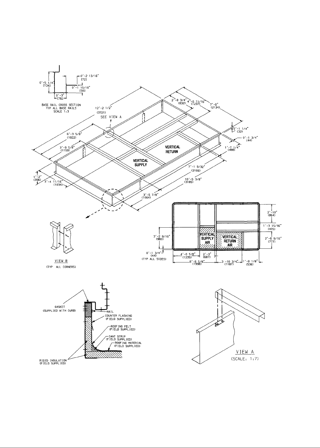
Roof Curb — Assemble and install as described in
instructions shipped with this accessory. Accessory roof curb
and information required to field fabricate a roof curb is
shown in Fig. 2a and 2b. Install insulation cant strips, roof
ing and counter flashing as required. For unit drains to func
tion properly, curb must be level or within tolerances shown
in Fig. 3.
Roof Mount — Check building codes for weight distri
bution requirements. Unit weight is shown in Tables la and
lb.
Slab Mount — Provide a level concrete slab that ex
tends beyond unit cabinet at least 6 Inches. Make a slab
8-in. thick with 4 in. above grade. (For condensate drain to
function properly, slab must be at least 4 in. above grade.
See Fig. 4.) Use gravel apron in front of condenser air inlet
to prevent grass and foliage from obstructing airflow.
Alternate Unit Support Methods Where the pre
ferred curb or slab mount cannot be used, support unit with
sleepers on perimeter, using curb support area. However, if
sleepers cannot be used, support long sides of unit (see
Fig. 5a — 5c) with three 4-in. x 4-in. pads equally spaced.
Unit may sag if supported by comers only.
Positioning — Provide clearance around and above unit
for airflow, safety, and service access. Allow 12 ft above
the unit, and at least 4 ft on all sides for rated performance
and code compliance. If unit has economizer, allow 6 ft
clearance on that side. For preferred service access, allow
6 ft clearance on all sides.
Do not install unit in an indoor location. Do not locate
air inlets near exhaust vents or other sources of contami
nated air.
Although unit is weatherproof, guard against water from
higher level runoff and overhangs.
IMPORTANT: Always line up the condenser end of
the unit tight against the roof curb.
Page 3
NOTES:
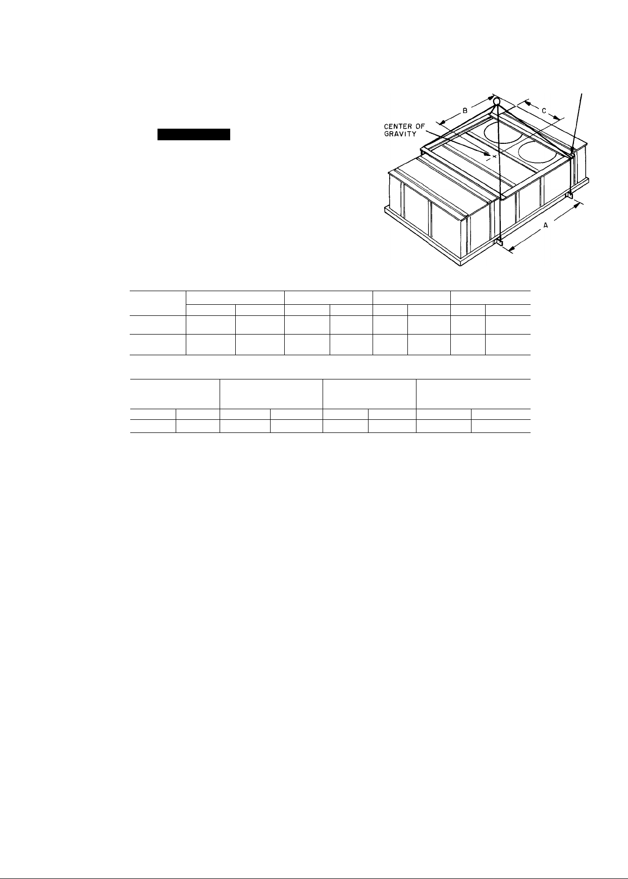
1 Rig with 4 cables and spread with two 95-in. (2413-mm) and
2 “A” long suitable spreader bars.
2 Center of gravity and unit weight include economizer, but not econ
omizer hood
f
1 All panels must be in place when rigging.
2. Unit is not designed for handling by forklift truck.
A CAUTION
MODEL
48LJD
49LJE
50LJ
50LW
ROOF CURB
Lb
280
NOTICE TO RIGGERS
UNIT WEIGHT A
Lb
2895
2975
2565 1164
2775
Kg
127
Kg
1313
1349
1259
ACCESSORY/OPTION WEIGHTS
ECONOMIZER
WITHOUT HOOD
Lb
140 63.6
In.
85 91
85.91
6.14 1680
85.91
Kg
mm
2182
2182
2182
ECONOMIZER
Lb
155
B
In. mm In. mm
61 1549 43 1092
61 1549 43 1092
49 1245
61
HOOD
Kg
1549 43
44
POWER EXHAUST/
BAROMETRIC
RELIEF HOOD
Lb
70.3 130 59.1
3/4 IN (19 MM) NOTCHES
IN END OF SPREADERS
C
1118
1092
Kg
Fig. 1 — Rigging Labei
Field-Fabricated Ductwork — Secure all ducts to
building structure, using flexible duct connectors between
roofcurb and ducts as required. Ducts passing through an
unconditioned space must be insulated and covered with a
vapor barrier. Outlet grilles must not lie directly below unit
discharge.
48LJ UNITS — These units are field-convertible with the
use of an accessory horizontal conversion kit. They are shipped
from the factory as vertical supply/retum, but may be field
converted to horizontal supply/retum.
Attach field-fabricated ductwork to the roof curb. The
retum-air duct connection (inside dimensions) is 46.75-in.
long X 30.59-in. wide; the supply-air duct connection (in
side dimensions) is 38.63-in. long x 27-in. wide. Connect
ductwork to 16-gage roof curb material. Secure all ducts to
the building structure, using flexible duct connectors be
tween roof curb and ducts as required. Ducts passing through
an unconditioned space must be insulated and covered with
a vapor barrier. Outlet grilles must not lie directly below
unit discharge. The return duct must have a 90-degree el
bow before opening into the occupied building space if unit
is equipped with power exhaust.
Vertical discharge ducts are designed to be attached to
accessory roof curb. If unit is mounted on dunnage, it is
recommended that the ducts be supported by cross braces
as shown for accessory roof curb. Duct should be the same
size as shown on the roof curb certified drawing.
Units may be connected to horizontal supply/retum
ductwork with the use of the accessory horizontal conver
sion package.
50LJ UNITS — On these units, attach field-fabricated
ductwork to roof curb. The retum-air duct connection
(inside dimensions) is 49.81-in. long x 30.59-in. wide; the
supply-air duct connection (inside dimensions) is 37.87-in.
long X 31.02-in. wide. Connect ductwork to 16-gage roof
curb material. (See installation instractions shipped with
accessory roof curb.)
50LW UNITS — On these units, attach field-fabricated
ductwork to factory-supplied duct flanges mounted on the
side of the unit. See Fig. 5c. Duct flange height is approx
imately one inch; flange is 18-gage sheet metal. The hori
zontal supply and return duct openings (inside dimensions)
are 26.85-in. wide x 42.03-in. high.
Page 4
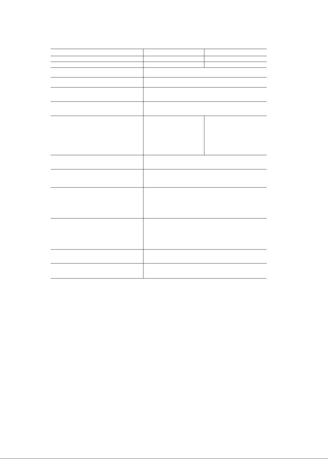
Table 1a — Physical Data, 48LJ Units
BASE UNIT 48LJ
NOMINAL CAPACITY (tons) lb
OPERATING WEIGHT (lb)*
COMPRESSORS (2 each unit)
Capacity Steps (%)
REFRIGERANT
Operating Charge (lb), Sys 1/Sys 2
CONDENSER COILS
Face Area (sq ft)
Fins Per In. (Al)
EVAPORATOR COILS
Face Area (sq ft)
Fins Per In.
FURNACE SECTION
Number of Heat Exchangers
Input (MBtuh)
Output (MBtuh)
Temperature Rise (°F)
Burner Orifice Diameter (in. ...drill no.)
Pilot Orifice Diameter (in. ...drill no.)
Firing Stages
Number of Gas Valves
CONDENSER FANS (2 each unit)
Nominal Cfm
Nominal Hp
EVAPORATOR FANS (1 each unit)t
Nominal Cfm
Maximum Allowable Cfm
Maximum Allowable Rpm
Standard Motor and Drive
Motor Hp
Full Load Efficiency (%)
Motor Frame Size
Fan Pulley Pitch Diameter (in.)
Motor Pulley Pitch Diameter (in.)
Resulting Fan Rpm
Optional Motor and Drive
Motor Hp
Full Load Efficiency (%)
Motor Frame Size
Fan Pulley Pitch Diameter (In.)
Motor Pulley Pitch Diameter (in.)
Resulting Fan Rpm
Optional Power Exhaust
Motors...Hp
Fans...Diameter (in.)
Filters (Quantity...L x W xD)
20% Standard Efficiency Disposable
'Weights include economizer, but not rainhood. See Fig. 1 for weights of options and accessories.
tStandard fan motor is supplied with standard fan drive and belts Optional motor is supplied with optional fan drive,
Centrifugai Type, 18 x 15-in., 1.438-in. Fan Pulley Bore
D024
20
2895
Hermetric, 3600 Rpm
50, 100
R-22 Controlled by Acutrol™ Metering Device
3-Row, %-in. Tube Diameter
4-Row, %-in. Tube Diameter
16 0/16.0
24.75
17.0
20.3
15
5
242
194
10-40
.129...30
.046...56
2
1
Propelier Type, 30-in. Diameter, 1130 Rpm
13,000
1 0
8,000
10,000
1,200
1750 Rpm
5
84.3
184T
10.6
4.75
780
1750 Rpm
7.5
84.8
213T
8.0
4.12
900
Propeller Type, 1140 Rpm
1.. 1.0
1 .24
2. 18 X 24 X 2
4...24 X 24 X 2
E024
20
2975
10
475
380
30-60
.129 ..30
.055...54
2
2
pulleys, and belts. Other combinations are field supplied.
Page 5
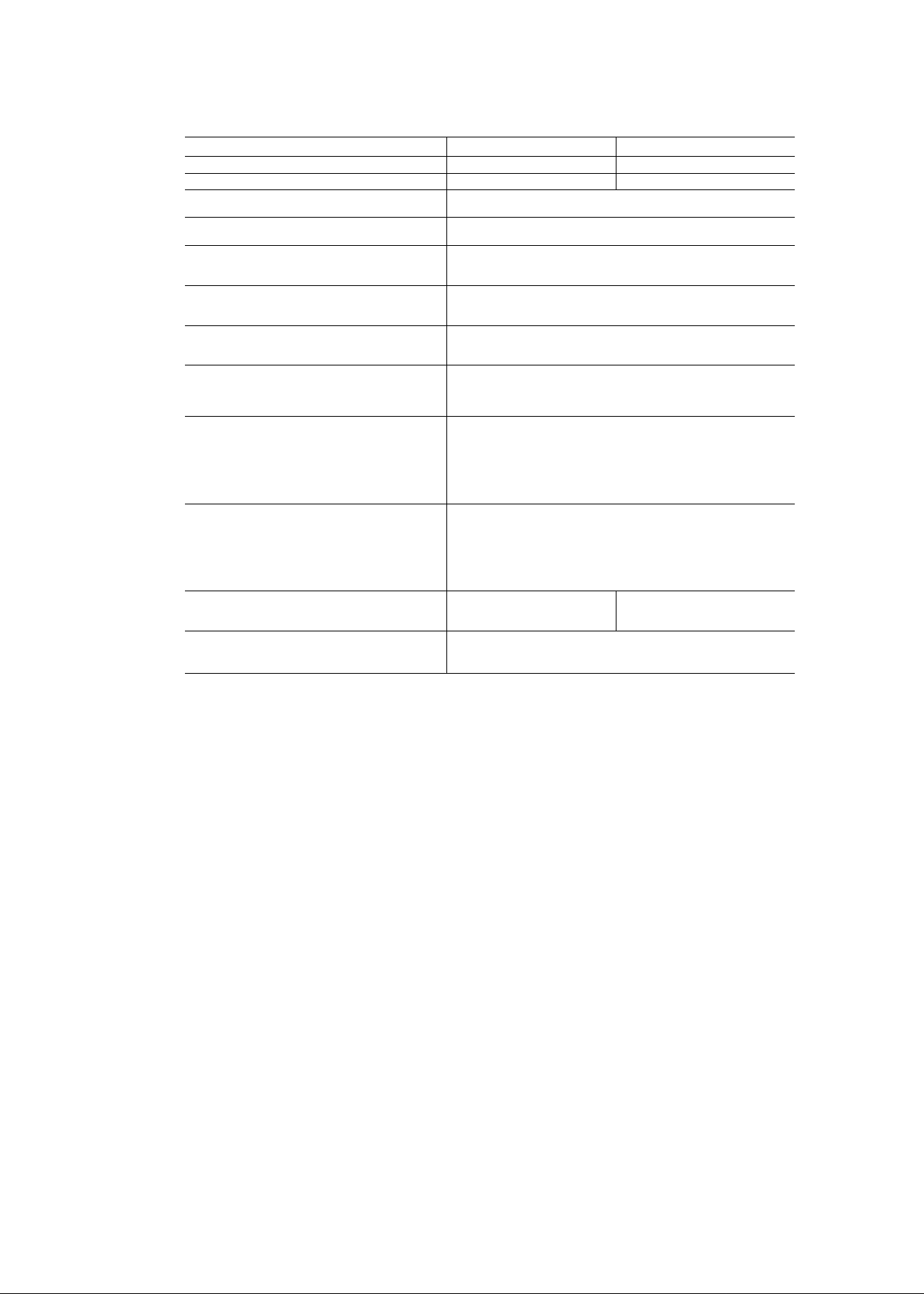
Table 1b — Physical Data, 50LJ/LW Units
BASE UNIT 50
NOMINAL CAPACITY (tons) 20
OPERATING WEIGHT (lb)*
COMPRESSORS (2 each unit)
Capacity Steps (%)
REFRIGERANT
Operating Charge (lb), Sys 1/Sys 2
CONDENSER COILS
Face Area (sq ft)
Fins Per In. (Al)
EVAPORATOR COILS
Face Area (sq ft)
Fins Per In.
CONDENSER FANS (2 each unit)
Nominal Cfm
Nominal Hp
EVAPORATOR FANS (1 each unit)t
Nominal Cfm
Maximum Allowable Cfm
Maximum Allowable Rpm
Standard Motor and Drive
Motor Hp
Full Load Efficiency (%)
Motor Frame Size
Fan Pulley Pitch Diameter (in.)
Motor Pulley Pitch Diameter (in.)
Resulting Fan Rpm
Optional Motor and Drive
Motor Hp
Full Load Efficiency (%)
Motor Frame Size
Fan Pulley Pitch Diameter (in.)
Motor Pulley Pitch Diameter (in.)
Resulting Fan Rpm
Optional Power Exhaust**
Motors...Hp
Fans...Diameter (in.)
Filters (Quantity...L x W xD)
20% Standard Efficiency Disposable
'Weights include economizer, but not rainhood. See Fig 1 for weights of options and accessories.
tStandard fan motor is supplied with standard fan drive, pulleys and belts Optional fan motor is supplied with op
tional fan drive, pulleys, and belts Other combinations are field supplied.
"Optional unit-mounted power exhaust not available on Model 50LW. Accessory power exhaust may be duct mounted
Centrifugal Type, 18 x 15-in., 1.438 in. Fan Pulley Bore
LJ024 LW024
20
2565
Hermetric, 3600 Rpm
50, 100
R-22 Controlled by Acutrol™ Metering Device
16.0/16.0
2775
3-Row, %-in. Tube Diameter
24.75
17.0
4-Row, %-in. Tube Diameter
20.3
15
Propelier Type, 30-in. Diameter, 1140 Rpm
13,000
1.0
8,000
10,000
1,200
1750 Rpm
5
84.3
184T
10.6
4.75
780
1750 Rpm
7.5
84.8
213T
80
4.12
900
Propeller Tyi
1. 1
1...24
De, 1140 Rpm
2...18 X 24 X 2
4 ..24 X 24 X 2
on 50LW installation
Page 6
NOTES:
1. Roofcurb accessory 50DJ900401 is shipped disassembled.
2. Dimensions in ( ) are in millimeters.
3 Roofcurb: 16 gage steel.
4. A 90 degree return duct elbow shall be provided for vertical
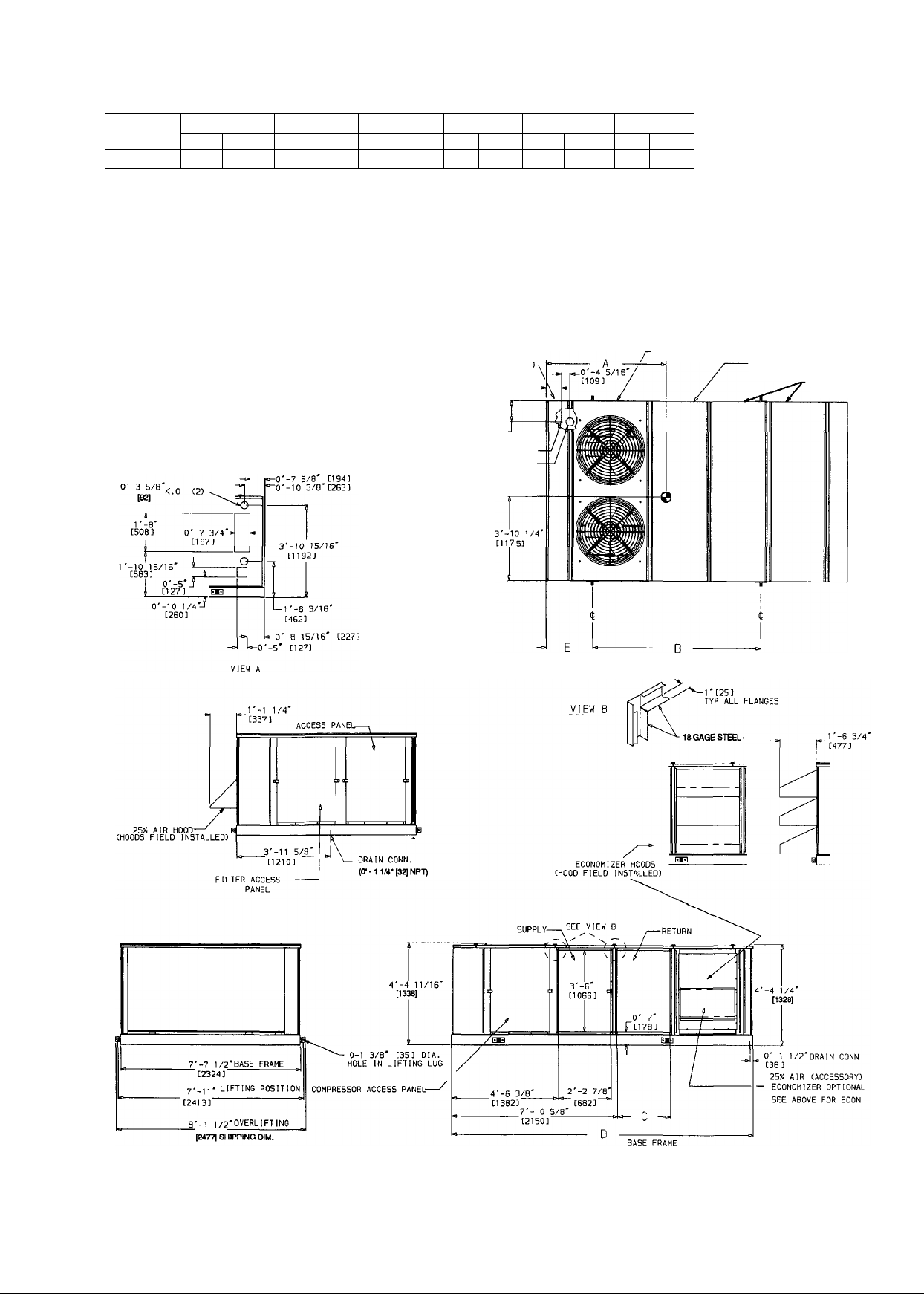
Fig. 2a — Roof Curb Details, 48LJ/50LW024 Units
Page 7

NOTES:
1. Roofcurb accessory 50DJ900391 is shipped disassembled.
2. Dimensions in ( ) are in millimeters.
3 Roofcurb: 16 gage steel.
4 A 90 degree return duct elbow shall be provided for vertical
return units equipped with power exhaust
5. A 90 degree supply duct elbow shall be provided for units
equipped with electric heat
Page 8
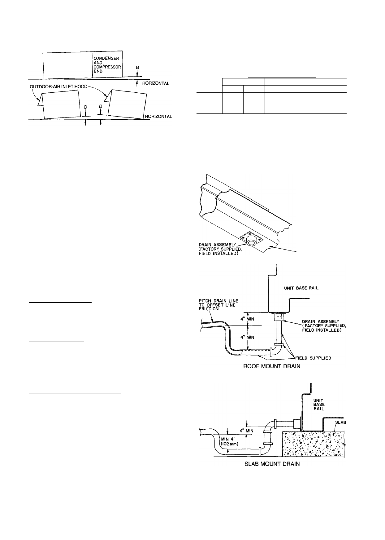
Fig. 3 — Unit Leveling Tolerances
Condensate Drain — See Fig. 5a - 5c for drain
location. A drain assembly consisting of a 10-gage plate
with PA in. half coupling welded to it is shipped inside the
base unit, taped to the basepan in the filter section. Open
the access panel marked FILTER SECTION and fine drain
assembly and the 4 screws required to mount it in the left-
hand comer. After unit has been set in place on the roof,
remove drain assembly and attach it to the bottom of the
unit base rail using the screws provided. See Fig. 4. Use a
trap at least 4-in. deep and protect against freeze-up.
NOTE: To prevent the hazard of stagnant water build-up in the drain
pan of the evaporator section, unit can only be pitched as shown.
See Table 1 for allowable B tolerances.
DIMENSIONS (degrees and In.)
UNIT B
Deg In.*
48U 1 38 4.00
50LJ 1.00 3.25
50LW
'From edge of unit to horizontal
1.38
4.00
Deg
.50
C
In.* Deg In.*
.75
.50
D
.75
On slab mount applications, and when mounted on
sleepers, seal hole in bottom of base rail and attach drain
assembly as low as possible to side of base rail.
NOTE: Drain hole must be drilled in rail. There is no factorysupplied drain hole in the side of the base rail.
Outdoor-Air Inlet Adjustments
ECONOMIZER SETTINGS
Enthalpy Sensor (Fig. 61 — This sensor is located on the
partition separating the outdoor air from the return air. See
Fig. 7. The enthalpy setting adjustment is on the top of the
economizer motor. See Fig. 8. For maximum benefit of out
door air, set enthalpy control to the A setting. See Fig. 8
and 9.
Mixed-Air Thermistor — The mixed-air thermistor (MAT)
set point adjustment is on the top of the economizer motor.
This motor is located in the retum-air section, and is
accessed by opening the access panel marked FILTER
SECTION. See Fig. 8. Set MAT set point adjustment dial
to the desired setting. The factory setting is 55 F ± 5° F;
the range is 40 to 90 F. The MAT is located on the filter
rack.
Minimum Damper Position Set Point — The minimum po
sition adjustment is located on the cover of the economizer
motor. See Fig. 8. Adjust by setting the fan switch to ON
position (continuous fan operation), and setting the system
selector switch to OFF position. Then turn adjustment screw
slowly until the dampers assume the desired vent position.
Do not manually operate the damper motor, damage to the
motor my result.
BOTTOM OF
BASE RAIL
Fig. 4 — Condensate Drain Piping Details
Page 9
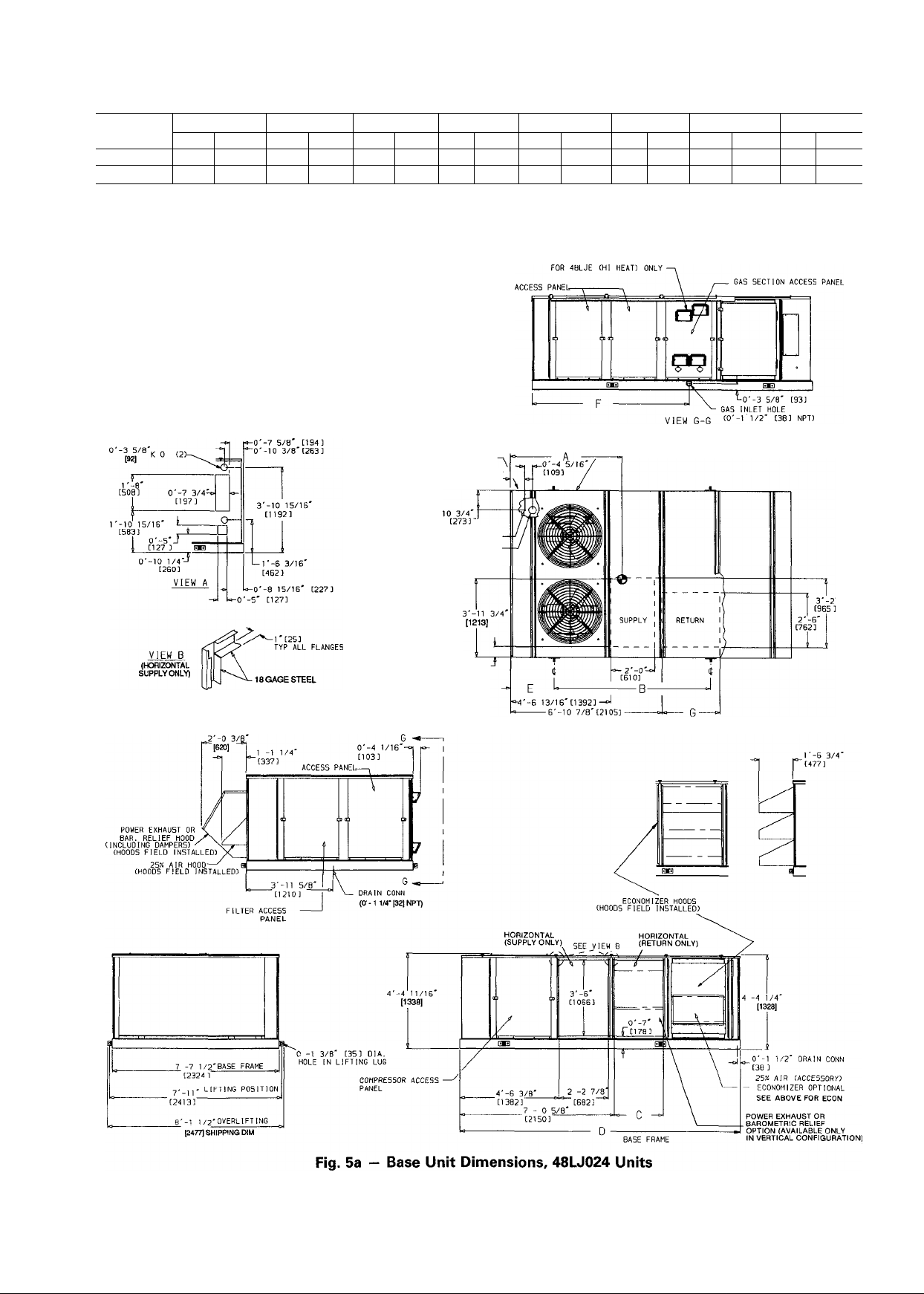
UNIT SIZE
48LJD024 2895 1313.0
48LJE024 2975
WEIGHT* A
Lb
Kg
1349.4 1813 6-1%
mm
Ft-in.
1813 6-1%
B C D
mm Ft-in. mm
2182
7-1%
2182 7-1%
Ft-in.
682 2-2%
682 2-2%
‘See note 9.
NOTES:
1 Dimensions in [
2.
Center of gravity.
are in miilimeters
3 Ailow 12'-0" [3658] at top and 6'-0" [1829] on sides for service and op-
erationai clearance.
4. On multiunit applications allow 12'-0" [3658] between adjacent condens
ers and economizers.
5. For smaller service and operational clearances, contact Carrier Appli
cation Engineering Department.
6. Vertical discharge ducts are designed to be attached to accessory roof
curb. If unit is mounted on dunnage, it is recommended the ducts be
supported by cross braces as done on the accessory roof curb.
7 Always line up condenser end of unit tight against the roof curb.
8. Units with power exhaust require a 90 degree elbow in return air duct.
9. Weight of unit includes optional economizer. For unit without econo
mizer, deduct 130 lb (59 Kg).
Ft-in. mm Ft-in.
mm
12-9% 534 1-9
3909
12-9% 534 1-9
3909
E F
mm
2187
2187
Ft-in. mm
7-2%4
807
7-2%4 807
G
Ft-in.
2-7%
2-7%
POWER IN (SIDE).
0'-3/4'
[13] NPT LOW VOLTASE
0'-3 1/2'
[89] NPT FIELD POWER
(SEE VIEW A)
0'-7 13/16:
[199]
0'-5 13/16'
[146]
/—CONTROL BOX ACCESS DOOR
Page 10
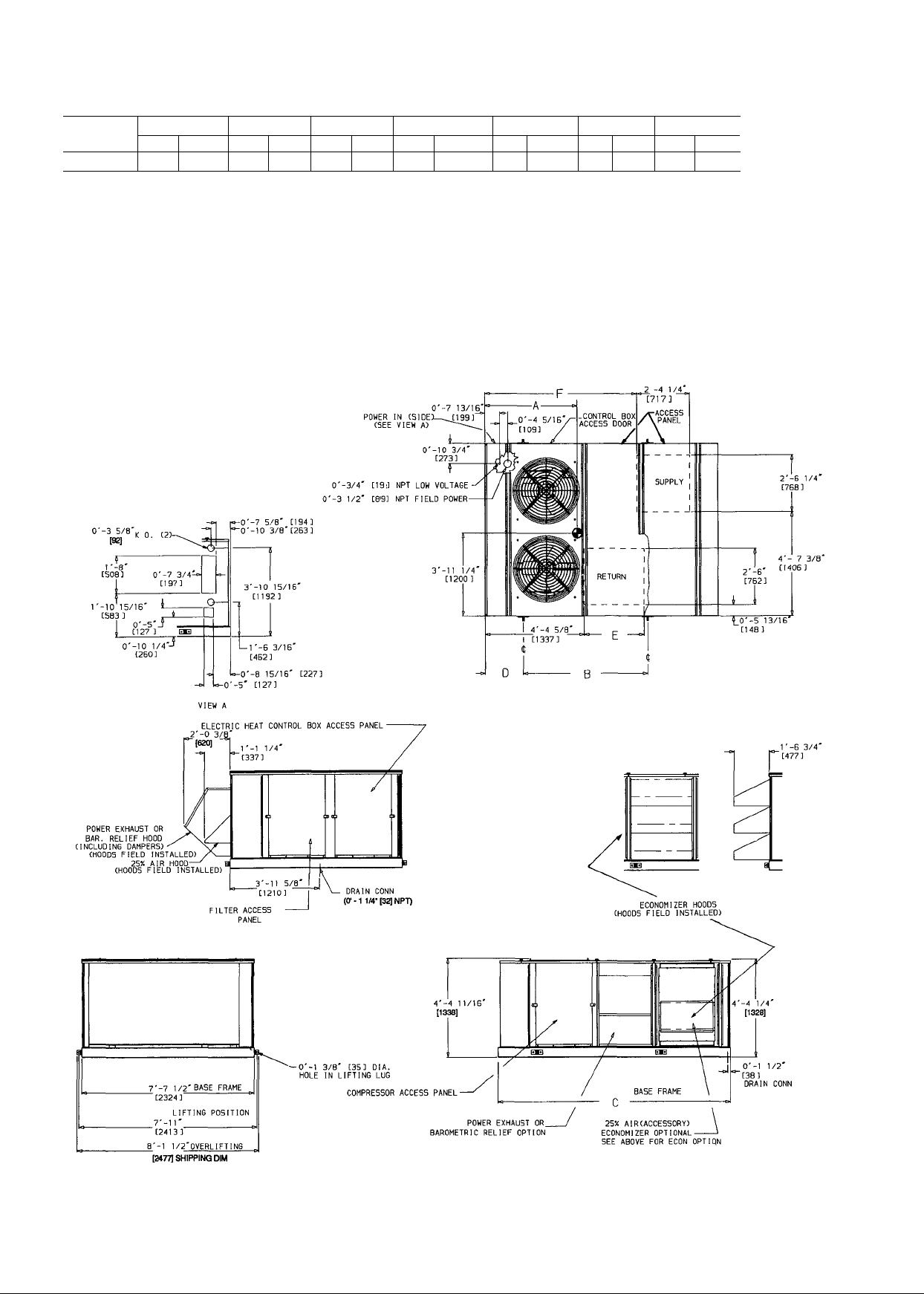
UNIT SIZE
50LJ024
WEIGHr
Lb
Kg
2565 1163.5
mm
1556
A
5-1V4
Ft-ln.
B
Ft-in
mm
5-6V8 3141 10-3'Vi 6
1680
C
D
mm Ft-in. mm Ft-in.
1-8"/i6 807 2-7% 2048 6-8%
526
E
mm Ft-in mm Ft-in.
*See note 10
NOTES:
1. Dimensions in [ ] are in miiiimeters.
Center of gravity.
3. Allow 12'-0" [3658] at top and 6'-0" [1829] on sides for service and operational clearance
4. On multiunit applications aliow 12'-0" [3658] between adjacent condensers and economizers
5. For smaller service and operational clearances, contact Carrier Application Engineering Department
6. Vertical discharge ducts are designed to be attached to accessory roof curb If unit is mounted on dunnage,
it is recommended the ducts be supported by cross braces as done on the accessory roof curb
7 Always line up condenser end of unit tight against the roof curb.
8 Units with power exhaust require a 90 degree elbow in return-air duct.
9. Units with electric heat require a 90 degree elbow in supply-air duct.
10 Weight of unit includes optional economizer For unit without economizer, deduct 130 lb (59 Kg)
F
Fig. 5b — Base Unit Dimensions, 50LJ024 Units
10
Page 11
mm
534
E
Ft-in.
1-9
UNIT SIZE
50LW024 2775 1258 7 1803
WEIGHr
Lb
Kg
mm
\ B
Ft-in
mm Ft-in.
2182 7-1% 682
5-11
C
mm Ft-in.
2-2%
D
mm Ft-in.
3909 12-9%
*See note 10
NOTES:
1. Dimensions in [ ] are in miiiimeters.
2 ® Center of gravity.
3 Allow 12'-0" [3658] at top and 6'-0" [1829] on sides for service and operational clearance.
4 On multiunit applications allow 12'-0" [3658] between adjacent condensers and economizers.
5. For smaller service and operational clearances, contact Carrier Application Engineering Department
6. Always line up condenser end of unit tight against the roof curb.
7. Weight of unit includes optional economizer. For unit without economizer, deduct 130 lb (59 Kg)
POWER IN (SIDE:
(SEE VIEW A)
0'-7 13/161
[193]
0'-3/4' [19] NPT LOW VOLTAGE
0'-3 1/2' [89] NPT FIELD POWER
-CONTROL BOX ACCESS DOOR
ELECTRIC HEAT CONTROL
BOX ACCESS PANEL
-ACCESS PANEL
f
Fig. 5c - Base Unit Dimensions, 50LW024 Units
11
Page 12
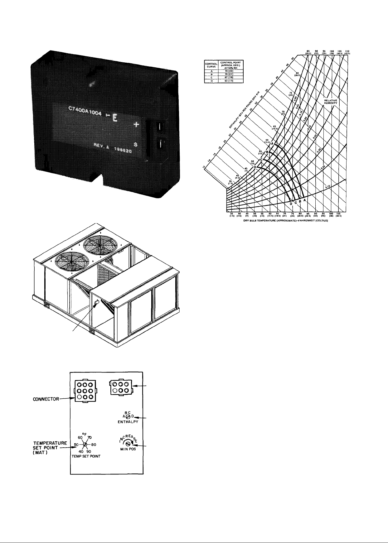
ENTHALPY SENSOR
Fig. 7 — Enthalpy Sensor Location
Fig. 6 — Enthalpy Sensor
■CONNECTOR
Fig. 9 — Setting "A" Operating Conditions
Install Outdoor-Air Hoods
ECONOMIZER HOODS — These hoods are shipped sep
arately from the base unit in a carton. This carton contains;
3 preassembled economizer hoods
1 filter angle
3 filter retainers
6 aluminum mesh cleanable filters, 16 in. x 20 in. x 2 in.
2 channel panels "I pj cross-section
1 channel clip J ®
1 fastener package (taped to a hood)
The fastener package contains;
8 capscrew bolts, V4—20 x '/2-in. long
8 nuts, '/4—20
18 screws, V4 AB x ys-in. long
8.3 ft of '/8-in. thick X '/2-in. wide seal strip with pressure-
sensitive adhesive on one side.
-ENTHALPY
-MINIMUM
POSITION
(CLOCKWISE
TO INCREASE)
Fig. 8 - Enthalpy Sensor Setting, Mixed Air
Thermistor (MAT) and Economizer Minimum
Position Adjustments (Top of Economizer Motor)
1. Remove the lag screws holding the economizer hoods
and channel panels to the shipping skid. (There are 4
lag screws per side.)
2. Remove the lag screws holding the filter angle and chan
nel clip to the shipping skid. (There are 2 lag screws
per part.)
3. The filters are wrapped to prevent shipping damage.
Remove the screws holding the filter retainers to the
hoods. (There are 4 screws per retainer.)
4. Remove wrap from filters. Do not reinstall until after
the hoods are mounted to the unit.
12
Page 13

IMPORTANT: If unit is to be equipped with
either barometric relief or power exhaust, the
barometric relief/power exhaust hood must be in
stalled prior to the installation of the economizer
hoods. If installing barometric relief or power ex
haust, proceed to the next section (Barometric
14. See Fig. 11 and place economizer hood assembly over
outdoor-air opening.
A CAUTION
Economizer hood assembly is heavy. At least 2
men should handle it.
Relief/Power Exhaust Hood) and install before pro
15.
ceeding any further. Then return to this point.
Line up the holes in the right channel panel with the
holes in the flange of the comer post. On 48/50LJ units,
line up the holes on the left channel panel with the holes
5. Place the hoods on a flat surface.
6. Insert the top flange of the middle hood flush with the
bottom flange of the top hood AND the top flange of
the bottom hood flush with the bottom flange of the
middle hood. When properly laid out the side flanges
of the 3 hoods should form one continuous flange.
7. See Fig. 10 and insert the capscrew bolts through the
flange holes as shown, from the back side, threads
facing outward. Note that though there are 12 holes (4
per hood) per side, only the 3 shown per side are to be
used.
8. If unit is not to be equipped with barometric relief or
power exhaust, discard the channel clip. If unit is to be
equipped with barometric relief or power exhaust, dis
card one of the channel panels.
9. Cut 2 pieces of seal strip 43V4 in. long for placement
on the channel panels (or one channel panel and one
channel clip if barometric relief or power exhaust is
used) on the flanges with the holes.
10. Begin one in. from the top of the flange and center the
seal strip on the flange, covering the holes.
NOTE: If seal strip is too high or too low, water leak
age may occur. Maintain the one in. dimension for
f
placement.
11. Using a punch or other tool, make holes in the seal
strip for screws.
on the flange of the panel next to the economizer sec
tion. On 50LW units, line up the holes on the left
channel panel with the holes in the flange of the return
duct flange. On units with barometric relief or power
exhaust, line up the holes in the channel clip with the
holes in the fan deck. (It is necessary to remove the top
and bottom screws from the fan deck to install econo
mizer hood assembly.)
16.
Once economizer hood assembly is in place, secure it
using 10 of the screws from the fastener package (5 per
side).
17.
Using 2 of the screws from the fastener package,
attach the top flange of the economizer hood assembly
to the unit top rail. The holes in the top rail are behind
the top rail gasket.
18.
Using 4 screws from the fastener package, attach top
and bottom of the channel panels and/or clips to the
top rail and the base rail. Again, the holes in the top
rail and the base rail will be covered by gasketing.
19.
Attach filter angle to base rail, using 2 screws from
fastener package. Since the holes are covered by the
base rail gasket, locate and punch them out before
attaching the filter angle.
20.
Seal any small gaps between flanges and at the top with
RTV sealant to prevent water leakage.
21.
Reinstall filters and filter retainers.
12. Place channel panels on the hood flanges, using the
middle 3 holes. If using barometric relief or power
exhaust, use the channel clip in place of the previously
discarded channel panel, attaching it to the left side of
the economizer hoods (left side when facing hoods).
13. Secure channel panels and/or channel clip to the hoods
using 6 of the nuts from the fastener package.
CROSS-SECTION
CHANNEL PANEL/CHANNEL CLIP
OF
Fig. 10 — Economizer Hood Assembly Holes
13
Page 14

BAROMETRIC RELIEF/POWER EXHAUST HOOD The same hood is used for barometric relief and power
exhaust, and is shipped separately from the base unit, in
cartons marked 50DJ900371.
Barometric relief can only be unit mounted on vertical
supply/return units (48/50LJ). It may be duct mounted on
horizontal supply/retum units (50LW).
Power exhaust can only be unit mounted on vertical supply/
return units 48/50LJ. Accessory power exhaust may be duct
mounted on horizontal supply/retum unit 50LW.
IMPORTANT: If using power exhaust, the return duct
must have a 90 degree elbow below the unit to com
ply with ANSI codes.
Cartons contain:
1 preassembled hood/damper assembly
1 fastener package (taped to inside of hood)
The fastener package contains:
6 screws, '/4 AB X %-in. long
2 seal strips 36-in. long x 1-in. wide x Vs-in. thick with
pressure-sensitive adhesive on one side.
2 seal strips, 33-in. long x 1-in. wide x Vs-in. thick with
pressure-sensitive adhesive on one side.
1. Remove the lag screws holding hood assembly to ship
ping skid. See Fig. 12.
2. Before installing the hood on the unit, remove the chan
nel panel attached to the barometric relief/power ex
haust fan deck and the panel to the left.
3. Remove the middle 2 screws holding the fan deck to
the base rail.
4. Apply the 36-in. long seal strips to the side flanges of
the hood assembly.
5. Apply the 33-in. long seal strips to the top and bottom
flanges of the hood assembly.
COMPRESSOR
ACCESS
PANEL
HOOD
Fig. 12 — Power Exhaust/Barometric Relief Hood
(50LJ Unit Shown)
6. Trim the excess seal strip as needed.
7. Make seal strips flush with the outer edges of the flanges.
8. Use a punch to punch out holes for the screws.
A CAUTION
Hood assembly is heavy. At least 2 men should
handle it.
Line up the top flange of the hood assembly with the 6
holes in the fan deck (approximately 6V2 in. from the
top.)
10.
Using the 6 screws from the fastener package, secure
the top flange of the hood assembly to the fan deck.
II.
Reinstall the 2 screws attaching the fan deck to the base
rail. (The holes in the bottom flange of the hood
assembly should line up with these holes.)
12.
Reinstall the channel panel between the fan deck and
the panel to the left. The 3 holes in the left side flange
of the hood assembly should line up with the corre
sponding holes in the fan deck and the channel panel.
The 3 holes in the right side flange of the hood assem
bly should line up with the holes in the fan deck and
the holes in the channel clip described in the earlier
section. Economizer Hoods. Unit is now ready for in
stallation of economizer hoods.
Field Wire Routing — Field wiring can be brought
into the unit from the bottom (though basepan and roof curb)
or through the side of the unit (comer post next to control
box).
A 31/2 in. NPT coupling for field power wiring and a
%-in. NPT coupling for 24-v control wiring are provided in
the basepan. In the side post, there are two 3% in. knock
outs for the field power wiring. If control wiring is to be
brought in through the side of unit, a "Vs-in. diameter hole
must be drilled in the condenser side post next to the con
trol box.
There are 2 large block-off plates in the comer post. The
smaller block-off (5 in. x 5 in.) is used to provide access to
main unit control box during installation of power wiring.
The larger block-off (7% in. wide by 20-in. high) is located
between the two 3-%in. knockouts and is used when a 400amp disconnect box is rewired.
If disconnect box is mounted to comer post, be careful
not to drill any screws into the condenser coil. The comer
post is marked to indicate the area where it is safe to drill
holes and install screws.
ROUTING THROUGH BOTTOM OF UNIT - If wiring
is brought in through bottom of unit, use field-supplied
watertight conduit to run power wiring from basepan out
through bottom 3% in. knockout to the disconnect box and
back into the main control box. When 200-amp or smaller
disconnect is used, the disconnect box should be located so
that wiring can be mn from back of disconnect box to unit
through top 3% in. knockout. Watertight strain relief (field
supplied) must be used in knockout. When 400-amp dis
connect is used, remove 7% in. x 20-in. block-off in comer
post and use field-supplied elbow to route conduit through
comer post to the control box.
Use strain relief going into control box through 4% in.
diameter hole provided. After wires are in unit control
box, connect to power terminal block. See power wiring
section on page 15.
Low-voltage wiring must be mn in watertight conduit from
the basepan to control box and through one-in. diameterhole provided in upper righthand comer of unit control box.
Field-supplied strain relief must be used going into the box.
After wiring is in control box, make connections to proper
14
Page 15

terminals on terminal blocks. See control wiring section on
page 17.
ROUTING THROUGH SIDE OF UNIT - When 200-amp
or smaller disconnect is used, route power wiring in
field-supplied watertight conduit into unit through 3Vs in.
knockout. Strain relief (field supplied) must be used in knock
out. When 400-amp disconnect is used, remove 7% in. x
20-in. block-off in comer post and use field-supplied elbow
to route conduit through comer post to the control box.
Use field-supplied strain relief going into control box through
4V2 in. diam hole provided. After wires are in unit control
box, connect to power terminal block. See power wiring
section below.
Bring low-voltage control wiring through field-drilled Vs-in.
diameter hole in condenser side post. Use strain relief go
ing into one-in. diameter hole in upper righthand comer of
unit control box.
After wiring is in control box, make connection to proper
terminals on terminal blocks. See control wiring section on
page 17.
Field Electrical Connections
POWER WIRING (All units) — Units are factory wired
for the voltage shown on the unit nameplate. The main ter
minal block is suitable for use with aluminum or copper
wires.
When installing units, provide a disconnect per NEC
(National Electrical Code) of adequate size (MOCP [max
imum overcurrent protection] of unit is on the informative
plate). All field wiring must comply with NEC and all local
codes. Size wire based on MCA (minimum circuit amps)
on the unit informative plate. See Fig. 13 for power wiring
connections to the unit power, terminal block and equip
ment ground.
Operating voltage to the compressor must be within the
voltage range indicated on the unit nameplate. Voltages be
tween phases must be balanced within 2%, and the current
must be balanced within 10%. See Tables 2 and 3 for unit
electrical data.
Use the following formula to determine the percent volt
age imbalance.
% Voltage Imbalance
= 100 X
max voltage deviation from average voltage
average voltage
Example: Supply voltage is 460-3-60
AB =452 V
BC =464 V
AC =455 V
Average Voltage
452 +462 -1-455
3
1371
= 457
Determine maximum deviation from average voltage:
(AB) 457 - 452 =5 v
(BC) 464 - 457 =7 V
(AC) 457 - 455 =2 v
Maximum deviation is 7 v.
Determine pereent voltage imbalance:
% Voltage Imbalance = 100 x
457
7
= 1.53%
This amount of phase imbalance is satisfactory as it is be
low the maximum allowable 2%.
IMPORTANT: If the supply voltage phase im
balance is more than 2%, contact local utility
immediately.
Unit failure as a result of operation on improper line
voltage or excessive phase imbalance constitutes abuse and
may cause damage to electrical components. Such opera
tion would invalidate any applicable Carrier warranty.
VOLTAGE
NOMINAL
V-PH-HZ
208/230-3-60
460-3-60 414 508 193
575-3-60
FLA — Full Load Amps
Hp — Nominal Horsepower
IFM — Indoor (Evaporator) Fan Motor
LRA — Locked Rotor Amps
RANGE
Max RLA LRA RLA LRA
Min
187 254 38.5
518
632
144
Table 2 — Electrical Data, 48LJ024
COMPR
NO. 1
193.0
96.5
77.2 144
LEGEND
MCA — Minimum Circuit Amps (for wire sizing)
MOCP — Maximum Overcurrent Protection
OFM — Outdoor (Condenser) Fan Motor
RLA — Rated Load Amps
COMPR
38 5
193
NO. 2
193.0
OFM
Total
FLA
10.8
96.5 5.4
77.2
48
15
Hp
50
7.5 22.0
50
7.5
50
7.5 86
IFM
FLA FLA
15.2
7.2
10.5
5.2
POWER
EXHAUST
FAN MOTOR
6.6/6.0
6.6/6.0
30.0
3.0
2.4
2.4
POWER SUPPLY
MCA
101 8/112.6
108.4/118 6
108.6/119.4
115.2/125.4
56.0
59 0
59.3
62.3
42.4
44 8
45.8
48.2
MOCP
Fuse Only
150/150
150/150
150/150
150/150
70
70
70
80
50
50
60
60
Page 16

Table 3 - Electrical Data, 50LJ,LW024
VOLTAGE
NOMINAL
RANGE
V-PH-HZ
Min
Max
208/230-3-60
187 254 38.5 193
460-3-60 508
632
*LJ units only
units only
tLW
FLA — Full Load Amps
— Nominal Horsepower
Hp
— Indoor (Evaporator) Fan Motor
IFM
— Locked Rotor Amps
LRA
COMPR
NO. 1
RLA
LRA
193 96.5
14.4 77.2
COMPR
NO. 2
RLA
LRA
38.5
193 96.5 5.4
14.4
77.2 48
LEGEND
MCA
MOCP
OFM
RLA
OFM
IFM
POWER
EXHAUST
FAN MOTOR
Total
FLA
Hp
FLA
FLA KW FLA
— — —
6.6/6.0
6.6/6.0 16/18 40.9/ 45.2
—
6.6/6.0
—
6.6/6.0 65/72*
—
—
6 6/6.0
—
6.6/6.0
—
6.6/6.0 33/36 81.8/ 90.4
—
6.6/6 0 65/72*
—
— —
30
—
193 108
15.2
5.0
7.5 22 0
3.0
3.0 36 45.2
—
30
— —
30
—
/
1 UéO
3.0 18 22.6 62.3
—
30 36 45.2 69.6
—
3.0
— -- —
24
5.0 5.6 2.4
7.5 8.6
— Minimum Circuit Amps (for wire sizing)
— Maximum Overcurrent Protection
— Outdoor (Condenser) Fan Motor
—
—
2.4 72*
_
— — —
2.4
—
24
—
2.4 72*
—
— Rated Load Amps
ELECTRIC
HEAT
—
16/18
33/36
33/36
65/72*
81/90t
—
—
16/18
16/18 40.9/ 45.2
33/36 81.8/ 90.4
65/72*
81/90t
— —
18 22.6
18 22 6
36
90t
90t
—
—
40.9/ 45.2 112.6/112.6
81.8/ 90.4 121 3/132.0 150/150
81.8/ 90.4 121.3/132.0 150/150
163.6/181.0
163.6/181.0
204.5/225.9
—
40.9/ 45.2 119.4/119 4
163 6/181.0
163.6/181.0
204 5/225.9 283.1/309.9
—
45 2 65.5
113.0
113.0
—
—
112.6/112.6
119.2/118.6
119.2/118.6
223 5/245 3
223.5/245 3
274.6/301.4
119.4/119 4
126.0/125.4
126.0/125.4
129.8/140.5
129.8/140.5
232.0/253.8 250/300
232.0/253.8 250/300
18 22.6
36 45.2 69.6
90t
90t
— —
36
36 36 1
72*
90t
««
36
36 36.1 55 9
72*
90t
113.0
113.0
36.1
72.3
72.3
90 4
—
36.1
72.3
72.3
90.4 123.8
POWER SUPPLY
MCA
MOCP
Fuse Only
150/150
150/150
150/150
150/150
225/250
225/250
300/350
150/150
150/150
150/150
150/150
150/175
150/175
300/350
56 0
56.0 70
56 0 70
59.0 70
65.5
150.3
150.3 175
59.3
62.3
62.3
154.4
154.4
42 8 50
45 2
52.1
52.1
97 4
97 4
120.0
45.8 60
48.2
175
175
175
125
125
125
55.9
101 1
101.1
125
125
125
70
70
70
70
80
70
80
80
80
50
50
50
60
70
70
16
Page 17

TBI
EQUIP GND
LEGEND
EQUIP — Equipment
GND — Ground
NEC — National Electrical Code
TB — Terminal Block
Fig. 13 — Field Power Wiring Connections
CONTROL WIRING — Install a Carrier-approved acces
sory thermostat assembly according to the installation
instructions shipped with the accessory. Locate thermostat
assembly on a solid wall in the conditioned space to sense
average temperature (where airflow is stable and thermostat
is not in direct line of supply-air duct). Route thermostat
cable or equivalent leads of no. 18 AWG (American Wire
Gage) colored wire from subbase terminals to 24-v terminal
strip (PI). The terminal strip is located on the constant
volume control board on units with no economizer and on
the economizer board on units with the economizer option
(see Fig. 14).
The total wire length between the unit and the thermostat
and the return wire from the thermostat to the unit should
not exceed the following limits: 50 ft of 18 AWG, 80 ft of
16 AWG or 125 ft of 14 AWG. See Fig. 15 for field wiring
connections between the thermostat and the unit 24-v ter
minal block.
There are no required 115-v field wiring connections, there
fore, no provisions have been made in the unit for running
115-v wiring. If any of the field-installed options requiring
115-v connections are desired, the unit must be modified in
the field for 115-v wiring.
Options requiring 24-v or 115-v control wiring are listed
below.
Building Pressurization or Smoke Purge Mode — Refer to
Building Pressurization Mode section and Smoke Purge Mode
section on page 24 for additional information. See Fig. 16
and unit wiring label for wiring details.
24-V Connections:
1. Firestat or smoke detector (field-supplied switch 1).
Remove factory-installed jumper wire and wire a fieldsupplied firestat or smoke deteetor between terminals
2 and 3 on terminal block 2 (TB2) in the unit eontrol
box (see Fig. 14 for the location of TB2 in the control
box).
2. Switch to supply 24-v power to the economizer motor
during building pressurization or smoke purge (fieldsupplied switch 5). Wire a normally-open switch
between terminal 3 on TB2 and terminal T1 in the econ
omizer motor.
3. Switch to open economizer outdoor air damper during
building pressurization or smoke purge (field-supplied
switch 6). Wire a field-supplied switch between termi
nals 8 and 9 on the economizer motor (in the top of
economizer motor). When this switch is manually opened,
it will drive the outside air damper fully open.
115-V Connections:
1. Building pressurization switch (field-supplied switch 2).
— Wire a field-supplied switeh between terminal 4 on
TB2 and the Cl connection on the evaporator-fan con
tactor coil (IFCl on unit label diagram).
2. Smoke purge switch (field-supplied switch 4). — Wire
a field-supplied switch between terminal 4 on TB2 (in
the unit control box) and the Cl conneetion on the power
exhaust eontactor coil (PECl on unit label diagram).
3. Switch to isolate evaporator-fan motor from power
exhaust motor during building pressurization or smoke
purge (field-supplied switch 3). — Wire a fieldsupplied switch in series with the wire from the Cl
eonnection on the IFCl to the red wire on the econo
mizer damper motor end switch (EDMS on unit label
diagram).
Convenience Outlet
115-V Connection: Convenience outlet can be mounted on
panel containing control circuit breakers CB3 and 4. (See
Fig. 14.) Remove sheet metal cover that conceals 2%
by
lVi6 in. hole and install outlet in hole. Wire between
terminals 4 and 5 on TB2 in the unit control box (see
Fig. 17). The convenience outlet should be ground fault
protected. Convenience outlet is to be used only when the
unit is not operating.
17
Page 18

COMPONENT ARRANGEMENT
CONTROL BOX
Page 19

ECONOMIZER
MOTOR
<S
<n>
<S>
€1>
(&>
€3
G> o
<3> O
mm
OO €9 t— econom:
<r> <±> r OPT
<D <±>
<2> ® \
<l>
O
M
_____
V
D№
DMS ^
REDY^L B^U
o
<D
____
GAS SECTION
€3
<[»
<D
O
(U LSI
Q>
CD
O LS2
G>
|0g><D|^^0<D|
DI1C3
I I HJ6H SAS
CD
G> G>
<3><2>®
<£>0<3>
H&V2
O
P6V2
<s o
C>0<D
O G>
CD ^
REDREO—
"1
c
B
Ì
'BLK
•YEL
<D*^0
'BLU
e>
575V GAS ONLY
€>
€>
TRAN 3
CD*
APS
HPS LPSl CH rn^^O
iiszi I182Í nS2( LJiK2|
Ö
<2> <S>
cow
IM <g)
2
C
B
1
50LJ_500___03£
Fig. 14 - Control Box Component Arrangement,
48/50LJ and 50LW Units
Page 20

LOW-VOLTAGE
TERMINAL BLOCK
IN UNIT CONTROL BOX (PI)
0
r-
&—J r~
@---------------' f
[wi]
---------------
^
------------------------
[y3----------------------
&
-------------------------------
0-
-----------------------
&
--------------------
--------------------g
--------------------g
----------------
1
I
------------------
1
____
THERMOSTAT/
SUBBASE
I
-------------------
-----
I
I—0]
J
-----------
^
0
0]
0
0
Fig. 15 - Field Control Thermostat Wiring
TB2
□
CONVENIENCE
OUTLET
1
--------
1
a
-0
-0
0
0
LEGEND
TB — Terminal Block
NOTES:
1 Convenience outlet is field supplied and installed. Ground fault
outlet should be used.
2.
_______
is field wiring.
0
Fig. 17 — 115-V Field Wiring
115V
LEGEND
c
ECON
IFC
Switch
Switch
Switch
Switch
Switch
Switch
— Contactor
— Economizer PEC
— Indoor (Evaporator)
Fan Contactor
Firestat or smoke detector — normally closed.
1 -
Building pressurization switch (energize evaporator-fan
2 -
motor) — normally open.
Switch to isolate evaporator-fan motor from power exhaust
3 -
motor — normally closed
Switch purge switch (energizer power exhaust motor) —
4 -
normally open.
Switch to provide 24 v to economizer motor — normally open.
5
6 -
Switch to drive economizer outdoor-air damper full open —
normally closed.
MTR — Motor
— Power Exhaust Contactor
PL
- Plug
— Terminal Block
TB
BUILDING PRESSURIZATION SMOKE PURGE
Switch 1 Switch 1
Switch 2 Switch 3
Switch 3 (if unit equipped with power exhaust) Switch 4
Switch 5 Switch 5
Switch 6 Switch 6
24 V
SWITCH 1 11?
I SWITCH 5
I
-----
—o-'—'o—
SEE NOTE 6
ECON MTR
SWITCH 6
NOTES:
Power exhaust option available only on vertical supply/return
units.
In order to Install Switch 1, field must remove factory jumper
between terminals 2 and 3 on terminal block 2
______
field wiring.
______
factory wiring.
All switches are field supplied.
6. Terminals 8 and 9 can be located by removing the top of the
economizer motor. Turn over top of motor to access the elec
tronic board and spade terminals.
Fig. 16 — Field Wiring for Building Pressurization
and Smoke Purge
20
Page 21

Gas Piping — Unit is equipped for use with natural gas
only. Installation must conform to local building codes, or
in the absence of local codes, with the NFGC (National
Fuel Gas Code), ANSI (American National Standards
Institute) Z223.1-1984.
i(f
A '/sin. NPT tapping plug, accessible for test gage con
nection, must be field installed immediately upstream of
gas supply connection to unit. See Fig. 18.
Natural gas pressure at unit gas connection must not be
less than 5 in. wg or greater than 14 in. wg.
Size gas supply piping for 0.5 in. wg maximum pressure
drop. Do not use supply pipe smaller than unit gas
connection.
(1) REGULAR INLET HOOD
A CAUTION
Disconnect gas piping from unit when leak testing at
pressures greater than 0.5 psig. Pressures greater than
0.5 psig will cause gas valve damage resulting in a haz
ardous condition. If gas valve is subjected to pressure
greater than 0.5 psig, it must be replaced.
UNION (FOR SERVICING)
*NPT plug is field supplied.
NOTE: Follow all local codes.
Fig. 18 - Gas Piping Detaiis
Installing Flue/lnlet Hoods — The flue/inlet hoods
are shipped in a bag taped to the basepan under the unit
fan. Remove the shipping block-offs and install hoods as
shown in Fig. 5a and 19. Use RTV sealant to provide rain
proof seal between hoods and door.
START-UP
Unit Preparation — Check to see that unit has been
installed in accordance with these Installation Instructions
and all applicable codes.
(2) HOOD WITHOUT BAFFLE (LOW HEAT ONLY)
Interhal Wiring — Check all electrical connections in
the unit control box; tighten as required.
Refrigerant Service Ports — Each unit system has
3 Schrader-type service ports, one on the suction line, one
on the liquid line, and one on the compressor discharge line.
Be sure that caps on the ports are tight.
Crankcase Heaters — The crankcase heaters must be
firmly locked onto the compressors. The crankcase heaters
are energized when there is power to the unit. Crankcase
heaters must be energized for at least 24 hours prior to unit
start-up in order to remove liquid refrigerant from the com
pressor crankcase.
Compressor Oil — All units are factory charged with
oil. The initial charge is 128 oz. The recharge is 124 oz.
See Carrier Standard Service Techniques, Refrigerants, for
procedures to add or remove oil.
Installation Locations for Flue Hood Assemblies
-
LOCATION
Hood Without Baffle (2)
UNIT
TYPE
High Heat
Low Heat
NOTE: Numbers in ( ) refer to type of hood to install in location
indicated.
“A” “B”
Hood With Baffle (3) Hood With Baffle (3)
Fig. 19 — Flue Hood Details
If it is necessary to remove oil, do not remove any oil
until the compressor crankcase heater has been ON for at
least 24 hours. When additional oil or a complete charge is
needed, use only Carrier-approved compressor oil.
21
Page 22

Approved oils:
Witco Co
.............................................................
Suniso 3GS
Texaco, Inc....................................................Capella WF-32
Do not use drained oil and do not use any oil that has
been exposed to the atmosphere.
Unit Voltage — Be sure power source agrees with the
unit nameplate rating.
Leak Test and Dehydration — Be sure there are no
refrigerant leaks. All units are shipped with a complete
operating charge of R-22 (Table 1) and should be under
sufficient pressure for leak testing after installation. If there
is no system pressure, add refrigerant until a pressure is
observed and then check for leaks. After leaks are repaired,
dehydrate the system. For leak testing and dehydration
procedures, see Carrier Standard Service Techniques,
Refrigerants, Sections 6 and 7. Do not use the system com
pressors to evacuate the system.
Evaporator Fan, Belt, and Sheaves — Belts, pul
leys, and sheaves are factory installed. All pulleys are
nonadjustable. See Table 1.
See Table 4 for complete listing of factory and fieldsuipplied pulley and belt combinations. See Table 5 for air
quantity limits.
Check the lubrication of fan and motor bearings. Bear
ings are shipped full of grease for corrosion protection and
may run warm temporarily on start-up until the excess grease
has discharged. Check bearing setscrews for tightness. Also
check the tightness of the setscrews on the fan wheel and
on the fan and motor sheaves. Check fan shaft bearing mount
ings for tightness.
Recheck sheave alignment and belt tension. See Adjust
ments section on page 26 for instructions.
Hand-turn the fan to make sure the fan wheel does not
rub on the fan housing. The fan shaft and motor shaft must
be freewheeling before power is applied to the unit.
Following the necessary electrical checks, check for fan
vibration. If excessive vibration occurs, check:
• drive misalignment
• sheaves eccentric or out of balance
• wheel out of balance (replace if necessary)
Check rotation of wheel with arrow on the fan housing.
Check fan speed with a strobe-type tachometer, or use this
formula:
Pan motor rpm x motor sheave pitch diameter (in.)
Rpm fan sheave pitch diameter (in.)
(Obtain motor rpm from the fan motor nameplate and
read sheave pitch diameters marked on the fan and motor
sheaves.
Example:
Nameplate motor rpm.......................................................1750
Motor sheave pitch diameter (in.)
.....................................
6.4
Fan sheave pitch diameter (in.) ........................................12.4
^ „ 1750 X 6.4
Fan Rpm =
---------
----------
= 903 rpm
The maximum allowable rpm is 1200. Excessive fan speed
may result in condensate carryover from the evaporator coil,
fan motor overload, or wheel failure. See Table 5 for Air
Quantity Limits.
Table 5 — Air Quantity Limits
UNIT
48LJD
48UE 6,162‘
50LJ,LW
‘Minimum cfm for heating operation.
MINIMUM
6,000
6,000
MAXIMUM
10,000
10,000
10,000
Condenser Fans and Motors — Each unit has 2
condenser fans and motors; these are factory set. See
Fig. 20 for correct location of fan in orifice. Check that
fan propeller rotation is correct; it should be counter
clockwise when facing the fans.
Return-Air Filters — Check that the correct filters are
installed in the filter rack. See Table 1 for quantities and
sizes. Access is through the door marked FILTER SEC
TION. Do not operate the unit without retum-air filters.
Economizer Inlet Screens —
place before operating the unit.
Check that they are in
Table 4 — Evaporator-Fan Pulley Data
UNIT
48U
50LJ
50LW
‘Indicates standard or optional pulley combinations available as shown in Tales la and 1b. All other
combinations are field supplied.
NOTE: The minimum speed with high eiectric heat option is 780 rpm
FAN
RPM
780‘
875
900*
980
1090
1160
780*
875
900*
980
1090
1160
780*
875
900*
980
1090
1160
MOTOR PULLEY
No. Grooves — Type — In. No. Grooves - Type — In. No. — Type — Size
2 - 3V - 4.75 2 - 3V - 10.6 2 - 3V - 850
2 - 3V - 5.30 2 - 3V - 10.6 2 - 3V - 850
2 - 3V - 4.12
2 - 3V - 4.50 2 - 3V - 8.0 2 - 3V - 800
3 - 3V - 5.00
3 - 3V - 5 30 3 - 3V
2 - 3V - 4.75 2 - 3V - 10.6 2 - 3V - 560
2 - 3V - 5.30 2 - 3V -106 2 - 3V - 560
2 - 3V - 4.12 2 - 3V - 8.0 2 - 3V - 500
2 - 3V - 4.50 2 - 3V
3 - 3V - 5 00
3 - 3V - 5 30
2 - 3V - 4.75
2 - 3V - 5 30
2 - 3V - 4.12 2 - 3V
2 - 3V - 4 50
3 - 3V - 5.00 3 - 3V
3 - 3V - 5.30 3 - 3V
BLOWER PULLEY
2 - 3V - 80
3 - 3V - 80
- 8.0 3 - 3V - 800
- 8.0
- 80
3 - 3V
- 8.0
3 - 3V
2 - 3V -106
- 10.6
2 - 3V
- 80
- 8.0
2 - 3V
- 8.0 3 - 3V - 800
- 8.0 3 - 3V - 800
22
BELT
2 - 3V - 800
3 - 3V - 800
2 - 3V - 500
3 - 3V - 500
3 - 3V - 500
2 - 3V - 850
2 - 3V - 850
2 - 3V - 800
2 - 3V - 800
Page 23

Economizer Dampers and Potentiometer Set
tings — With no power to the unit, the economizer outdoor-
air dampers should be fully closed. Check by opening
the access door marked FILTER SECTION. On units with
economizer, be sure MAT and economizer minimum posi
tions are set at the desired settings. Be sure hood is in
stalled properly.
Fig. 20 — Condenser-Fan Adjustment
Operating Sequences
COOLING, UNITS WITHOUT ECONOMIZER - Set unit
power to ON position. Set system selector switch at COOL
or AUTO, position, and fan switch at AUTO, position. Set
thermostat at setting below room temperature.
Y1 on the thermostat closes, energizing Compressor
no. 1 as first stage of cooling. (Compressor no. 1 is closest
to the condenser coil.) The evaporator fan starts at the same
time as Compressor no. 1. If cooling load cannot be satis
fied with only first-stage cooling, Y2 on the thermostat will
close, energizing Compressor no. 2.
Condenser fans are energized with Compressor no. 1. The
no. 1 fan runs continuously while the unit is on mechanical
cooling; the no. 2 fan is cycled on and off for head pressure
control. Check cooling effects at a setting above room tem
perature. Compressors will shut off.
HEATING, UNITS WITHOUT ECONOMIZER
48LJD (Low Heatl — Purge gas supply line of air by open
ing union just ahead of the unit gas valve. When odor of
gas is detected, retighten union and wait 5 minutes before
proceeding.
Set unit power to ON position. Open manual gas valve
supplying gas to unit. Set thermostat system switch at HEAT
or AUTO, position, and set fan switch at AUTO, position.
First-stage thermostat (Wl) calls for heat. Induced-draft
contactor closes and induced-draft and evaporator-fan
motors start.
Centrifugal switch closes. Induced-draft motor operates
for 30 seconds to purge combustion tubes. Pilot valve opens,
allowing gas to flow to first-stage pilot. Spark ignitor
ignites pilot flame. Sensor detects flame, energizes main
gas valve coil and main gas valve opens. Gas flows to main
burners, and first-stage burners ignite. Spark ignitor shuts
off and pilot remains on.
The sparker will continue to spark for 90 seconds, or
until pilot flame is sensed. If the pilot fails to ignite or the
sensor fails to detect flame, the pilot valve closes, and the
spark ignitor shuts off for 330 seconds (51/2 minutes). Dur
ing this time, the induced-draft motor remains on to purge
any unbumed gas from the combustion tubes. This ignition
sequence will continue indefinitely.
On low-heat units 48LJD, when additional heat is needed
W2 is energized and a second coil in the main gas valve is
energized. This brings on an additional stage of heat. When
second-stage thermostat is satisfied, the second-stage gas
valve coil is deenergized.
When the first-stage thermostat is satisfied, first-stage main
gas valve and the pilot valve close. Induced-draft motor shuts
off. Evaporator fan motor stops.
48L.IE tHiuh Heat) — Purge gas supply line of air by open
ing union just ahead of the unit gas valve. When odor of
gas is detected, retighten union and wait 5 minutes before
proceeding.
Set unit power to ON position and open manual gas valve,
supplying gas to unit. Set thermostat system switch at HEAT
or AUTO, position, and set fan switch at AUTO, position.
First-stage thermostat (Wl) calls for heat and evaporator
fan starts.
When evaporator fan starts, airflow switch closes, clos
ing induced draft contactor, and induced draft motor starts.
Centrifugal switch closes. The induced-draft motor
operates for 30 seconds to purge combustion tubes. Pilot
valve opens, allowing gas to flow to first-stage pilot. Spark
ignitor ignites pilot flame. Sensor detects flame, energizes
main gas valve coil, and main gas valve opens. Gas flows
to main burners and first-stage burners ignite. Spark ignitor
shuts off and pilot remains on.
The sparker will continue to spark for 90 seconds, or
until pilot flame is sensed. If the pilot fails to ignite, or the
sensor fails to detect flame, the pilot valve closes, and the
spark ignitor shuts off for 330 seconds (51/2 minutes). Dur
ing this time, the induced-draft motor remains on to purge
any unbumed gas from the combustion tubes. This ignition
sequence will repeat indefinitely.
When additional heat is needed, W2 is energized after a
30-second delay. Pilot valve no. 2 opens, allowing gas to
flow to second-stage pilot. Spark ignitor ignites pilot flame.
Sensor detects flame, energizes main gas valve coil, and
main gas valve no. 2 opens. Gas flows to main burners and
second-stage burners ignite. Second-stage spark ignitor shuts
off. The induced-draft motor operates for 30 seconds to purge
combustion tubes. When the second-stage thermostat is sat
isfied, W2 is de energized and the second gas valve is shut
off.
When the first-stage thermostat is satisfied, first-stage main
gas valve and the pilot valve close. Induced draft motors
and evaporator-fan motor shut off.
50LJ (With Optional Electric Heat) — Set unit power at
ON position. Set system selector switch at HEAT position,
and set fan switch at AUTO, position. Set thermostat at
setting above room temperature.
When Wl on the thermostat closes, the first stage of elec
tric heat is energized. On a further drop in room tempera
ture, W2 on the thermostat closes, energizing the second
stage of electric heat.
NOTE: Units equipped with low electric heat option have
only one stage. Reset thermostat to a setting below room
temperature. Unit should shut off.
COOLING, UNITS WITH ECONOMIZER - With sub
base switch set at COOL and fan switch set at AUTO.,
evaporator fan is energized when Y1 on thermostat closes.
If enthalpy is below setting on enthalpy switch, the econo
mizer outdoor-air dampers will modulate open to satisfy the
cooling requirement. (Evaporator-fan motor heat should be
considered when evaluating the use of outdoor air to satisfy
23
Page 24

cooling requirements.) If outdoor air alone will not meet
the cooling requirements, Y2 on the thermostat will close,
energizing Compressor no. 1 to work in conjunction with
the modulating economizer to meet the cooling require
ment. While the unit is operating using outdoor-air. Com
pressor no. 2 cannot be energized. If enthalpy is above
setting on enthalpy switch, the economizer outdoor-air damp
ers move to the minimum (ventilation) position, and con
denser fans nos. 1 and 2 cycle on and off as described in
Cooling, Units Without Economizer section on page 23.
NOTE: If fan switch is in ON position, and the room ther
mostat is satisfied, the outdoor-air dampers move to the min
imum position.
HEATING, UNITS WITH ECONOMIZER - Operation
is the same as described in Heating, Units Without Econo
mizer section on page 23, except that the outdoor-air
dampers move to the minimum position.
BUILDING PRESSURIZATION MODE - Building pres
surization is used to pressurize conditioned space in the event
of a fire or smoke condition. For building pressurization
mode to work effectively, unit must be equipped with econ
omizer option. On a large building with multiple zones, it
may be desirable to pressurize a zone that does not have
smoke in it to keep smoke from entering the zone from other
zones that may be filled with smoke.
In building pressurization mode, supply-air fan operates
with outdoor-air dampers wide open (on units with econo
mizer) and, if unit is equipped with power exhaust option,
the power exhaust fan off. This pumps outdoor air into the
zone but does not exhaust it, resulting in the zone becom
ing positively pressurized.
All switches and wiring required for building pressuriza
tion must be field supplied and wired.
To go into pressurization mode, power to the control
circuit must be interrupted. This can be done using alarm
relay contacts described in 115-V Connections section on
page 17. These contacts can be energized by a relay in a
smoke detector, a firestat, or by a relay that is manually
energized in a central control room. Switches must be field
installed to energize supply-air fan and drive economizer
dampers wide open. After power to control circuit is inter
rupted, these switches must be manually closed to put unit
into pressurization mode; switches would probably be lo
cated in central control room. If unit is equipped with return/
exhaust fan option, return-air fan should be off.
SMOKE PURGE MODE — In order to use smoke purge,
unit must be equipped with power exhaust option.
Smoke purge is used to exhaust smoke from a zone in
the event of a fire or heavy smoke condition. In this mode,
power exhaust fan runs, supply fan is shut off, and econo
mizer dampers are wide open. With power exhaust fan run
ning and exhaust damper wide open, smoke-filled air is
exhausted out of the conditioned space to the outdoors.
With smoke purge mode, it is necessary to interrupt power
to unit control circuit as described above for building pres
surization. All switches and wiring for putting unit into smoke
purge mode must be field supplied and installed. Terminals
have been provided in unit control box to facilitate field
hookups.
The field-installed switches must energize return-air fan
and drive economizer dampers wide open. After power is
interrupted to unit control circuit, these switches must be
manually closed to place unit into smoke purge mode. As
with building pressurization switches, these switches would
probably be located in a central control room.
NOTE: With both building pressurization and smoke purge
modes, do not overpressurize the zone; unit will keep pump
ing air in or exhausting air out until told to do otherwise.
Ventilation Air Circulation (Continuous Fan) —
Set unit power at ON position, system selector switch at
OFF, HEAT, or COOL position and fan switch at ON
position.
Evaporator-fan contactor is energized through the switch
on the thermostat and the evaporator fan runs continuously.
Automatic Changeover Using Automatic
Changeover Thermostat — Set unit power at ON
position, and system selector switch at AUTO position.
When the temperature of the conditioned space rises to
the cooling selector lever setting, unit automatically switches
from the heating mode to the cooling mode. When the tem
perature of the conditioned space falls to the heating selec
tor switch setting, unit automatically changes from cooling
mode to heating mode. The thermostat is interlocked so that
cooling and heating systems do not operate at the same time.
Head Pressure Control — All units have a fan
cycling thermostat which cycles the no. 2 condenser fan.
(The no. 2 condenser fan is located over the control box.)
This switch opens at 60 F ± 3° F and closes at 70 F ±
3 ° F. This allows the unit to operate down to 20 F outdoor
ambient temperature.
NOTE: Accessory Motormaster® head pressure control is
available which allows mechanical cooling down to
-20 F.
SERVICE
Service Access — All unit components can be reached
through clearly labeled removable access panels, with the
exception of the unit control box. Access to the unit control
box is through a hinged access door.
Access panels are held in place by 2 latches (one on each
side) and 4 screws in the bottom flange. To remove panels:
1. Loosen the latch bolt using a Yis-in. wrench and pivot
the latches so they are not in contact with the panel.
2. Using a Vs-in. wrench, remove the 4 screws in the bot
tom flange.
3. Pull the bottom of the panel out and down to remove.
To replace panel:
1. Place top edge of panel under drip lip at top.
2. Push panel up and in.
3. Replace 4 screws at the bottom.
4. Tighten latches.
The control box access door is not equipped with tiebacks, so if heavy-duty servicing is needed, either remove
the door or prop it open to prevent accidental closure.
The door is held closed with 3 latches. The latches are
secured to the unit with a single l/i-in. — 20 x Vi-in. long
bolt. To open, loosen the latch bolt using a Vie-in. wrench.
Pivot the latch so that it is not in contact with the door, and
open the door. To shut, reverse the above procedure.
24
Page 25

NOTE: Disassembly of the top cover may be required un
der special service circumstances. It is very important that
the orientation and position of the top cover be marked on
the unit prior to disassembly. This will allow proper place
%
ment of the top cover onto the unit and prevent rain water
from leaking into the unit.
IMPORTANT: After servicing is completed, make sure
door and panels are closed and latched properly, and
that all latches are tight and all screws are replaced
and tight. Failure to do this can result in water leak
age into the evaporator section of the unit.
COMPRESSORS — Access to the compressors is through
the access panel on the right side of the unit (when facing
the condenser coil). This panel also provides access to the
crankcase heaters and the high- and low-pressure switches.
Compressor no. 1 is compressor closest to the condenser
coil.
EVAPORATOR-FAN MOTORS, PULLEYS, AND BELTS
— Access to these components is through the panel labeled
FAN SECTION on the left side of the unit (when facing
condenser coil).
FILTER DRIERS — Access to the filter driers is through
the panel on the right on the evaporator end of the unit (end
opposite the condenser coil).
COMBUSTION-AIR BLOWER — Clean periodically to
assure proper airflow and heating efficiency. Inspect blower
wheel every fall and periodically during the heating season.
For first heating season, inspect blower wheel bimonthly to
determine proper cleaning frequency. Inspect wheel by shin
ing a flashlight into the opening. If cleaning is required,
remove blower assembly from unit and then disassemble as
shown in Fig. 23.
ELECTRIC HEAT CONTROL BOX (Fig. 24)
5QLJ Units — On these units, access to the electric heat
control box is through the panel marked FAN SECTION on
the back end of the unit. (End opposite condenser coil.) Be
sure to use the correct panel, as there are 3 panels labeled
FAN SECTION.
50LW Units — On these units, access to the electric heat
control box is through the panel marked HEAT SECTION.
HEATER BOX
50LJ Units — Access to the heater box on these units is
through the last panel on the left side of the unit (when
facing condenser coil). Panel is marked FAN SECTION.
Box is mounted directly under evaporator fan.
50LW Units — Access to the heater box on these units is
through the panel marked HEAT SECTION.
NOTE: Only the heater element connectors are located in
the heater box. The heater elements themselves are in the
airstream.
UNIT CONTROL BOX — Access to this component is
through the panel marked ELECTRICAL SECTION on the
left side of the unit (when facing condenser coil). See
Fig. 14 for control box component locations.
GAS HEAT SECTION — Access to the gas heat section is
through the panel labeled HEAT SECTION on the left side
of the unit (when facing condenser coil). See Fig. 21
and 22.
All gas system components are in the gas section, except
the limit switch(es). Find the limit switch(es) in the upper
right side of the compressor section, behind the suction bell
of the right compressor. Limit switch(es) is covered by a
rainshield and held in place by 2 screws.
MAIN AND PILOT BURNERS — At the beginning of each
heating season, inspect for deterioration due to corrosion or
other causes. Observe the pilot and main burner flames through
the viewport (contained in the condenser section), and ad
just if necessary. See Automatic Pilot Adjustment section
on page 28 or Main Burner Adjustment section on page 28.
FLUE GAS PASSAGEWAYS — The flue collector box
and heat exchanger cells may be inspected by removing the
combustion-air blower(s), flue box cover, and main burner
assembly. See Fig. 21 and 22 for proper removal sequence.
If cleaning is required, remove heat exchanger baffles through
the flue box and clean all parts with a wire brush. When
replacing heat exchanger baffles, be sure to replace screw
through clamp on baffle retaining rod into the vestibule plate.
BURNER SECTION
Fig. 21 — Gas Section Detail,
48LJD (Low Heat)
25
Page 26

VIEW A-A
BURNER SECTION
Fig. 22 - Gas Section Detaii,
48LJE (High Heat)
ECONOMIZER DAMPER MOTOR — On units so equipped,
the economizer motor is located on a bracket in the returnair section. Access to it is through the panel labeled FIL
TER SECTION on the far end of the unit (when facing
condenser coil).
POWER EXHAUST MOTOR — Remove the power ex
haust hood to gain access to motor.
RETURN-AIR FILTERS — Access to these filters is through
the panel marked FILTER SECTION.
CONDENSER FANS AND FAN MOTORS - Remove the
wire fan guard on top of the unit to gain access to the con
denser fans and motors.
Cleaning — inspect unit at the beginning of each heat
ing and cooling season and during each season as operating
conditions may require.
Clean condenser coil with a vacuum cleaner, fresh
water, compressed air, or a bristle brush (not wire). Coil
cleaning should be a part of the planned maintenance pro
gram. Clean evaporator coil with a stiff bristle brush (not
wire), vacuum cleaner, or compressed air.
Check and clean condensate drain annually at the start of
the cooling season. In winter, keep drain and traps dry and
protect against freeze-up.
Replace return-air filters at the start of each heating and
cooling season and as often as necessary during each
season, depending on operating conditions. See Tables la
and lb for filter types, quantities, and sizes.
Remove economizer outdoor-air filters from the hoods
by removing the filter retainers. Clean filters with steam or
hot water and mild detergent. Reinstall in hoods after clean
ing. Never replace cleanable filters with disposable filters.
Fig. 23 — Combustion Blower Removal
LEGEND
FB — Fuse Block
FU - Fuse
HC - Heater Contactor ELECTRIC HEAT BOX
Fig. 24 — Typical Electric Heat Control Box
Component Arrangement
Lubrication
COMPRESSORS — Each compressor is correctly charged
at the factory.
FAN SHAFT BEARINGS — Lubricate fan shaft bearings
at least once a year with suitable bearing grease. Typical
lubricants are given below:
MANUFACTURER
Texaco
Sunoco
Texaco
Mobil
’Preferred lubricant because it contains rust and oxidation
inhibitors.
LUBRICANT
Regal AFB-2*
Prestige 42
Multifak 2
Mobilplex EP No. 1
FAN MOTOR BEARINGS — The condenser-fan motors
and the evaporator-fan motor(s) have sealed bearings, so no
field lubrication is required.
DOOR HINGES — The control box door hinges should be
lubricated at least once a year.
Adjustments
EVAPORATOR-FAN MOTOR PLATE — Adjust using a
'Vie-in. wrench on the bolts shown in Fig. 25 and 26. Turn
the bolts counterclockwise to move the motor mounting plate
toward the fan and loosen the belts; turn clockwise to move
the plate away from the wheel and tighten the belts. Make
the same number of turns to each bolt.
I
26
Page 27

BELT INSTALLATION AND TENSIONING
NOTE: When installing or replacing belts, always use a
complete set of new, matched belts. Mixing belts often
results in premature breakage of the new belts.
1. Turn off unit power.
2. Adjust motor plate so belts can be installed without stretch
ing over the grooves of the pulley. (Forcing the belts
can result in uneven belt stretching and a mismatched
set of belts.)
3. Before tensioning the belts, equalize belt slack so that it
is on the same side of the belt for all belts. Failure to do
so may result in uneven belt stretching.
4. Tighten belts using the motor plate adjusting bolts.
5. Adjust until proper belt tension ('/2-in. deflection with
one finger) is obtained. Be sure to adjust both adjusting
bolts the same number of turns.
6. Check the tension at least twice during the first day of
operation; there is normally a rapid decrease in tension
until the belts have run in. Check tension periodically
thereafter and keep it at the recommended tension.
With the correct belt tension, belts may slip and squeal
momentarily on start-up. This slippage is normal and dis
appears after wheel reaches operating speed. Excessive belt
tension shortens belt life and may cause bearing and shaft
damage.
PULLEY ALIGNMENT — For proper belt life, the motor
and fan pulleys must be properly aligned. To check:
1. Turn off unit power. See Fig. 27.
2. Place a straight edge against the motor and fan pulleys.
If the pulleys are properly aligned, the straight edge should
be parallel to the belts.
3. If they are not parallel, check that the motor shaft and
fan shaft are parallel. If they are not, adjust the motor
plate adjusting bolts until they are.
4. After verifying that the shafts are parallel, loosen the
setscrews on the motor pulley.
5. Move pulley on the shaft until the pulleys are parallel.
6. To move the sheave on the shaft, loosen the belts. If
necessary, blower pulley can also be moved on the shaft.
INSTALLING FIELD-SUPPLIED ALTERNATE MO
TOR PULLEY — To install the alternate pulley:
1. Turn off unit power.
2. Loosen belts using motor adjusting bolts until belts can
be removed without stretching them over the grooves of
the pulley.
3. Remove belts.
4. Loosen setscrews on motor pulley.
5. Slide pulley off motor shaft. Make sure setscrews on
new pulley are loose.
6. Slide new pulley onto fan shaft and align it with the fan
pulley as described above.
7. Tighten setscrews.
8. Install belts and tension properly as described above.
CONDENSER FAN — To adjust condenser fans:
1. Turn off unit power.
2. Remove fan guard and loosen fan hub setscrew.
3. See Fig. 20 and adjust fan height using a straight edge
laid across the fan deck.
4. Tighten setscrew and replace rubber hubcap to prevent
hub from rusting to the motor shaft. Fill hub recess with
Permagum if hub has no rubber hubcap.
5. Replace fan guard.
27
Page 28

CENTER LINES
5. With a small screwdriver, turn adjustment screw until
flame fully engulfs sensor.
6. Replace cap on pilot gas valve. Turn off power to unit.
Return valve(s) to original position.
7. Check for proper burner operation by cycling the burn
ers. Wait 30 seconds between burner cycles.
8. Check that all doors are closed securely before leaving
the unit.
GAS VALVE ADJUSTMENT - The gas valve opens and
closes in response to the thermostat or limit control. When
power is supplied to valve terminal 3 (D1 on low-heat), the
pilot valve opens to the preset position. When power is sup
plied to terminal 2 (W1 on low-heat), the main valve opens
to its preset position.
The regulator factory manifold pressure setting is stamped
on the valve body (2.7 in. wg on high-heat units and 2.9
in. wg on low-heat units).
Manifold pressure is the pressure at the factory-supplied
pressure tap on the manifold downstream of the gas valve.
This is not the same as the pressure at the tap on the gas
valve body. Always use the tap on the manifold to read
manifold pressure.
To adjust regulator:
1. Set thermostat at setting for no call for heat.
2. Turn main gas valve to OFF position.
3. Install a suitable pressure measuring device.
4. Set main gas valve to ON position.
5. Set thermostat to call for high fire (W2).
6. Remove screw cap or plastic cover covering the regula
tor adjustment screw.
7. Turn adjustment screw clockwise to increase pressure or
counterclockwise to decrease pressure.
8. Once desired pressure is established, remove pressure
measuring device and replace the screw cap.
PILOT LIGHT OFF — If pilots do not light as described in
Heating section on page 23, be sure that pilot orifice is
unobstructed, then check for spark ignitor malfunctions.
If pilot flame is not sensed within 90 seconds, pilot and
main gas valves will close and will remain off for a 330second purge before ignition retry. The ignitor will retry
ignition indefinitely while a call for heating exists.
1. Shut off control supply power to Ignitor Control Pack
(ICP).
2. Check that spark gap is Vs-in. ± V32 inch.
3. Check that ICP is securely grounded.
4. Check that the high-voltage lead is securely connected
between ICP and electrode body.
5. Restore power to ICP. Check that 24 v is supplied to
terminal TH of the ICP.
6. Check unit label diagram for correct terminal usage if
any wires are removed.
AUTOMATIC PILOT ADJUSTMENT
1. Set system selector switch at OFF position to shut off
unit. Turn off power to unit.
2. Remove screw cap cover on pilot gas valve to expose
adjusting screw.
3. To ensure that main burners do not ignite, remote wire
from gas valve terminal 2. Tape wire. Do not allow wire
to be grounded.
4. Turn on power to unit. Set system selector switch to
HEAT position and set thermostat to a setting that will
call for heat. Pilot ignites.
MAIN BURNER ADJUSTMENT — Main burners are fac
tory set and should require no adjustment. However, if burner
adjustment is necessary:
1. Perform Automatic Pilot Adjustment as instructed above.
2. Turn gas valve to ON position. Allow unit to operate at
least 15 minutes with heat section access panel closed.
3. Open heat section access panel.
4. Loosen primary air shutter and adjust to a minimum open
ing of Vs inch.
5. Retighten primary air shutter and close access panel.
To check ignition of main burners and fan switch oper
ation, move thermostat dial above and below room temper
ature several times, pausing at least one minute between
cycles.
MAIN BURNER REMOVAL
1. Shut off main gas valve.
2. Shut off power to unit.
3. Unplug PL9, (and PL 10 on high heat) and all sensor and
ignitor wires.
4. Disconnect gas connection(s) from between gas valve(s)
and field-supplied piping. See Fig. 21 and 22.
5. Remove 2 screws securing burner assembly to unit.
6. Slide burner assembly from unit.
NOTE: For high-heat units (Models 48LJE) the side posts
must be removed before the burner assembly can be
removed.
28
Page 29

ENTHALPY CONTROL, MAT, AND ECONOMIZER
DAMPER VENT POSITION — See Installation section of
this publication for adjustment procedures.
AUXILIARY SWITCH — All units have an auxiliary switch
located on the economizer damper motor. This switch is
factory set to prevent the power exhaust from operating when
the economizer damper is less than 50% open. If other than
the factory setting is desired, follow the steps below.
A CAUTION
Do not turn motor shaft by hand or with a wrench.
Damage to the gear train will result.
Remove top cover from motor to gain access to motor
terminals and cam adjustments.
Disconnect controller from motor. Connect red, white,
2.
and blue terminals on the 135 ohm manual potentiome
ter to corresponding red, white and blue terminals on
the motor. Connect 24-vac power to Terminals 1 and 2.
See Fig. 28.
3. Adjust the 135-ohm potentiometer so that the motor shaft
turns to the position where auxiliary equipment is to be
switched.
4. Adjust auxiliary cam by inserting a Vs-in. straight blade
screwdriver into slot on cam and moving TOP of screw
driver to the right or left. See Fig. 29.
5. To close auxiliary switch red and blue contacts as the
motor travels open (energizing the power exhaust mo
tor), the switch differential can only be 10 degrees on
both switches. To adjust either cam, perform the fol
lowing steps:
a. If red and blue contacts are open, rotate the cam
counterclockwise until the contacts close.
b. If the red and blue contacts are closed, rotate the cam
clockwise until the contacts open.
6. Check for proper auxiliary switching (including differ
ential) by mnning motor through full stroke, using 135
ohm potentiometer. Repeat adjustment if necessary.
7. Disconnect 135 ohm potentiometer, reconnect control
ler and place top cover on motor.
TO ADJUST CAMS,
MOVE TOP OF SCREWDRIVER ONLY
AUXILIARY END VIEW
Fig. 29 — Auxiliary Switch Adjustment
NOTE: Adjusting the auxiliary switch does not require run
ning the motor.
REFRIGERANT CHARGE — All units are shipped with a
complete operating charge of R-22. See unit nameplate and
Tables la and lb for amount of charge. When charging
refrigerant system, refer to Carrier Standard Service Tech
niques, Refrigerants section. When adding a complete charge,
evacuate system using standard evacuating procedures and
weigh in the specified amount of charge. See Fig. 30 for
refrigerant circuit charging chart.
Fig. 28 — Auxiliary Switch Stroke Adjustment
Refrigerant Feed Components — Each refrigerant
circuit (2 per unit) has all the necessary refrigerant
controls.
Acutrol™ Refrigerant Metering Device - Each
circuit has 12 non-adjustable metering devices. They con
trol the flow of liquid refrigerant to the evaporator coils.
Filter Drier — Replace whenever refrigerant system is
exposed to atmosphere.
Protective Devices
COMPRESSOR PROTECTION
Overcurrent (208/230 v onlvl — Each compressor has one
manual reset, calibrated trip, magnetic circuit breaker. Do
not bypass connections or increase the size of the circuit
breaker to correct trouble. Determine the cause and correct
it before resetting the breaker.
29
Page 30

689
621
3^52
o
in
¡483
UJ
cc
S 41 4
in
cc
Q.
2 345
z
o
5276
:d
in
207
111 M 1 1
OUTDO OR TEMP
F C
115 46
?"
105 41
95 35
in
a.
a:
13
in
in
z
_J
o
rj
in
1
"1
«
2=
y'
>
'
>
X'
?
y
85 29
75 24
65 18
>
55 13
45 7
350 4
JCTION L
1 1 1 1 1 1 1
-1 4 10 16 21 27
SUCTION LINE TEMPERATURE (C)
0 5
NE TEMPE
0 6
RATURE C
0 7 F)0 8
0
Fig. 30 — Charging Chart
Overtemperature — Each compressor has an internal pro
tector to protect it against excessively high discharge gas
temperatures.
r.rankcase Heater — Each compressor has a 70-watt crank
case heater to prevent absorption of liquid refrigerant by oil
in the crankcase when the compressor is idle. Since 115-v
power for the crankcase heaters is drawn from the unit con
trol circuit, main unit power must be on for the heaters to
be energized.
IMPORTANT: After a prolonged shutdown or ser
vice job, energize the crankcase heaters for 24 hours
before starting the compressors.
Compressor Lockout — If any of the safeties (high-, lowpressure, compressor internal thermostat) trip, or if there is
loss of power to the compressors, the constant volume con
trol board will lock the compressors off. To reset, manually
move the thermostat setting.
EVAPORATOR FAN MOTOR PROTECTION - A man
ual reset, calibrated trip, magnetic circuit breaker protects
against overcurrent. Do not bypass connections or increase
the size of the breaker to correct trouble. Determine the
cause and correct it before resetting the breaker.
CONDENSER-FAN MOTOR PROTECTION - Each
condenser-fan motor is internally protected against over
temperature. Each motor is also protected against a severe
overcurrent condition by manual reset, calibrated trip, mag
netic circuit breakers. As with the circuit breakers
described previously, do not bypass connections or in
crease breaker size to correct trouble. Determine the cause
and correct it before resetting the breaker.
HIGH- AND LOW-PRESSURE SWITCHES - See Fig. 31
for compressor mounting locations. Settings for these switches
are shown in Table 6. If either switch trips, or if the
compressor overtemperature switch activates, that refriger
ant circuit will be automatically locked out by the constant
volume control board. To reset, manually move the ther
mostat setting.
Table 6 - Pressure Switch Settings (psig)
SWITCH CUTOUT
High 426 ± 7 320 ± 20
Low
7 ± 3
CUT-IN
22 ± 5
Relief Devices — All units have relief devices to pro
tect against damage from excessive pressures (i.e., fire).
These devices protect the high and low side.
Control Circuit, 115-V - This control circuit is pro
tected against overcurrent by a 5-amp circuit breaker. Breaker
can be reset. If it trips, determine cause of trouble before
resetting.
Control Circuit, 24-V — This control circuit is pro
tected against overcurrent by a 3.2-amp circuit breaker. Breaker
can be reset. If it trips, determine cause of trouble before
resetting.
Gas Heat
LIMITS SWITCHES — The maximum supply air temper
ature is controlled by a limit switch located in the compres
sor section. The limit is designed to trip at 100° F above the
maximum temperature shown in Table 1.
When the limit trips, the gas valve is deenergized and the
combustion air blower(s) and evaporator fan are held on
until the unit is cooled to its reset temperature. Once the
unit cools, the gas valve is reenergized.
If the thermostat stops calling for heat after the limit switch
trips, the combustion-air blower and evaporator fan are held
on until the limit cools to its reset temperature.
ROLLOUT SWITCH — This switch senses any flame or
excessive heat in the main burners and deenergizes the gas
valve. If this occurs, the gas heating system is locked out
until the rollout switch is reset manually. Reset by pressing
the button on the rollout switch. See Fig. 21 and 22.
When the rollout switch trips, it likely indicates a flue
blockage. Inspect the unit for any obstruction in the flue
system, for holes on the flue box, or for a defective
centrifugal switch or a loose combustion blower. See
Fig. 32 for proper location of the rollout capillary.
AIRFLOW SWITCH, 48LJE (HIGH HEAT) UNITS ONLY
— Shuts off the gas heat in the event there is a loss of air
over the gas cells. The airflow switch is located in the fan
section (see Fig. 5a — 5c). The switch will automatically
reset when airflow is sufficient.
30
Page 31

Fig. 32 — Location of Rollout Switch Capillary Tube
Electric Heat
OVERCURRENT — Heaters are protected by fuses in the
power circuit, located in the heater control box. As with
circuit breakers, determine the cause of fuses tripping be
fore replacing them. Do no replace with larger fuses. All
fuses are 60 amp, except for the 18-kW, 460-v heater, which
uses 35-amp fuses.
OVERTEMPERATURE — Heaters are protected by limit
switches mounted in the heater box. They reset automati
cally once they cool.
Control Board Checkout — The following tools are
required to perform the troubleshooting tasks detailed in this
section:
1.5-v battery
2 sets of jumper wires with alligator clips
Multimeter
Toggle switch with 14-in. wires terminated with V^-in.
spade connectors
A DAHGER
Read these instractions completely before attempting
to troubleshoot the control board. Failure to follow the
steps precisely could result in damage to unit, personal
injury or death.
The control board checkout procedure consists of 3 parts:
1. A basic check to verify availability of 24 and 115 v to
the control board.
2. A detailed check of each circuit within the board.
3. A continuity check for the economizer board.
BASIC CHECK — Refer to Fig. 33 for control board com
ponent identification.
IMPORTANT: If unit is equipped with an econo
mizer option, disconnect and remove the economizer
control board.
NOTE: All plugs (except PI) are labeled for easy identifi
cation. Plug PI can be identified by its orange color.
1. Turn unit power off. Disconnect plug PI from control
board.
2. Turn unit power on and check voltage across Pin R and
Pin C at plug PI. If voltage reads 18 to 30 v, skip to
Step 5.
3. Turn unit power off. Disconnect plug P3.
4. Turn unit power on and measure voltage across wires on
plug P3, Pins 1 and 2 (wires coming from the unit). If
voltage reads 18 to 30 v, there is either a bad connection
between plug P3 and control board, or the control board
is defective. Verify the connection at this point and pro
ceed to Step 5. If there is no voltage, check the circuit
breaker and transformer in the 24-v control circuit of the
unit.
5. Turn unit power off and disconnect plug P4 from the
control board.
6. Switch scale on meter to read 115 v.
7. Turn unit power on and check voltage across Pin 6 on
plug P4 and unit ground (wires coming from the unit).
If voltage reads 104 to 122 v, there is adequate power
available to the board. Verify connection at this point
and proceed to Step 8 below. If there is no voltage, check
the circuit breaker and transformer in the 115-v control
circuit of the unit.
8. After verifying that 24-v and 115-v supply power is avail
able to the control board, turn power off and reconnect
plugs PI, P3 and P4. Proceed to Detailed Check section
below.
DETAILED CHECK
NOTE: Plug PI must be disconnected in order to perform
any of the troubleshooting steps detailed in this section. To
save time, reconnect plug PI only after you have com
pleted all of the required troubleshooting.
31
Page 32

PI
Symptom: Evaporator Fan Will Not Operate.
1. Turn unit power off and disconnect plug PI from the
control board.
2. Install a jumper across Pin R and Pin G at plug PI on
the control board.
3. Turn unit power on and check if the evaporator-fan con
tactor (IFC) coil has been pulled in. If the contactor has
not been pulled in, check the voltage across the IFC coil.
If there is voltage at this point, the IFC contactor is de
fective. If there is no voltage, proceed to Step 4.
4. Turn unit power off and disconnect plug P4 from the
control board.
5. Turn unit power on and check for continuity across Pin
6 and Pin 3 at plug P4 on the control board. If there is
no continuity, the board is defective. Replace control
board. If there is continuity, then there is a bad con
nection between the board and plug P4. Correct the
connection.
6. Turn unit power off. Reconnect plug PI (if troubleshoot
ing is complete) and plug P4.
Symptom: Condenser Fan No. 1 Will Not Operate.
1. Turn unit power off. Disconnect plugs PI and P3 from
the control board.
2. Check for continuity between Pin 8 at plug P3 on the
control board and Pin Y1 on the control board. If there
is no continuity, the board is defective. If there is con
tinuity, either the connection is bad between plug P3
and the control board or the problem is external to the
board. Reconnect plug PI (if troubleshooting is com
plete) and plug P3 to the board.
Symptom: Condenser Fan No. 2 Will Not Operate.
Check operation of condenser fan no. 1. If fan no. 1 op
erates properly, the problem is external to the board.
Symptom: Compressor No. 1 Will Not Operate.
1. Turn unit power off. Disconnect the 2 wires attached to
the terminals marked SCI.
2. Check continuity between the 2 wires. If there is no con
tinuity, the problem is external to the control board
(possibly the pressure switches). If there is continuity,
proceed to Step 3.
3. Reconnect the wires removed in Step 1 above.
4. With the unit power still off, disconnect plug PI from
control board. Install a jumper wire across Pin R and
Pin Y1 at plug PI on the control board.
5. Connect a voltmeter across the coil for Compressor no.
1 contactor.
6. Energize unit and monitor the voltage for a few
seconds.
IMPORTANT: Do not run compressor too long.
If proper voltage is indicated at the contactor, but
7. a.
contactor fails to close, replace contactor.
If voltage is indicated for a few seconds (i.e., the
b.
contactor momentarily pulls in and is then de
energized), the Compressor Lockout (CLO) logic has
shut down the unit. This is an indication that the board
is not sensing proper compressor current, or that one
of the safeties has tripped. Proceed to Step 8 to ver
ify compressor lockout logic operation.
If proper voltage is indicated at the contactor and con
c.
tactor closes, the board is operating properly.
/
32
Page 33

8. To verify compressor lockout logic:
a. Disconnect CLO sensor wires connected to CLOl at
the control board. Check wires for continuity. If there
is no continuity, replace the sensor.
b. Connect the multimeter to read voltage between Pin
X at plug PI and ground.
c. Turn unit power on and check the multimeter. Within
a few seconds the meter should indicate 24 v. If it
does not, the control board is defective and must be
replaced.
d. Turn unit power off. Use a toggle switch to connect
a fresh 1.5-v battery to the terminals marked CLOl
as shown in Fig. 34.
A CAUTION
The negative (- Ve) pole of the battery must be
connected to the inner terminal and the positive
(+ Ve) pole must be connected to the outer ter
minal as shown in Fig. 34.
Turn unit power on and use the toggle switch to make
e.
and break the connection between the outer CLOl
terminal and the positive (-h Ve) pole of the battery.
If the multimeter shows 24 v when battery is dis
connected and no voltage when the battery is con
nected, the CLO logic is good. If the multimeter shows
no change, the CLO logic is defective and the board
must be replaced.
Symptom: Compressor No. 2 W ill Not Operate.
1. Be sure unit power is OFF. Disconnect the 2 wires at
tached to the terminals marked SC2.
2. Check continuity between the 2 wires. If there is no con
tinuity, the problem is external to the control board
(possibly the pressure switches). If there is continuity,
proceed to Step 3.
3. Reconnect the wires removed in Step 1 above.
4. Turn unit power off. Disconnect plug PI from the con
trol board and install jumper wire across Pins R and Y2
at plug PI. (This may have already been done in the
Compressor no. 1 troubleshooting section.)
5. Connect a voltmeter across the coil for Compressor no.
2 contactor.
6. Energize unit and monitor the voltage for a few
seconds.
IMPORTANT: Do not run compressor too long.
7. a.
If proper voltage is indicated at the contactor, but
contactor fails to close, replace contactor.
b.
If voltage is indicated for a few seconds (i.e., the
contactor momentarily pulls in and is then de
energized), the Compressor Lockout (CLO) logic has
shut down the unit. This is an indication that the board
is not sensing proper compressor current, or that one
of the safeties has tripped. Proceed to Step 8 to ver
ify compressor lockout logic operation.
If proper voltage is indicated at the contactor and con
tactor closes, the board is operating properly.
33
P I
Page 34

8. To verify compressor lockout logic;
a. Disconnect CLO sensor wires connected to CL02 at
the control board. Check wires for continuity. If there
is no continuity, replace the sensor.
b. Connect the multimeter to read voltage between Pin
X on plug PI and ground.
c. Turn unit power on and check the multimeter. Within
a few seconds the meter should indicate 24 v. If it
does not, the control board is defective and must be
replaced.
d. Turn unit power off. Connect a fresh 1.5-v battery to
terminal marked CL02 as shown in Fig. 34.
A CAUTION
The negative (-Ve) pole of the battery must be
connected to the inner terminal and the positive (+ Ve)
pole must be connected to the outer terminal as shown
in Fig. 34
e. Turn unit power on. Make and break the connection
between the outer CL02 terminal and the positive
( + Ve) pole of the battery.
f. If the multimeter shows 24 v when the battery is dis
connected and no voltage when the battery is con
nected, the CLO logic is good. If the multimeter shows
no change, the CLO logic is defective and the board
must be replaced. Remove all jumpers and replace all
plugs except plug PI. (Replace plug PI only if no
further troubleshooting is required.)
Symptom: First or Second Stage of Heating Will Not
Operate.
1. Turn unit power off. Disconnect plugs PI and P3.
2. Check continuity between Pin W1 at plug PI and Pin 5
at plug P3. If there is continuity, the board is good and
the problem is either the connection at P3, or external to
the control board. If there is continuity, the control board
is defective and must be replaced.
3. Check continuity between Pin W2 at plug PI and Pin 7
at plug P3. If there is continuity, the board is good and
the problem is either at the connection at plug P3 or ex
ternal to the board. If there is no continuity, the board is
defective and must be replaced. Reconnect plug P3 to
the control board. (Reconnect plug PI only if no further
troubleshooting is required.)
Symptom: Evaporator Fan Will Not Energize On a Call
For Heat.
1. Turn unit power off. Disconnect plug PI and plug P4.
2. Install jumper wire between Pin R and Pin W1 at plug
PI.
3. Turn unit power on. Check for continuity between Pin 6
and Pin 3 at plug P4 on control board.
4. If there is no continuity between these points, the board
is defective and must be replaced.
NOTE: The control board (part number HK37AA001)
has no time delay.
5. If there is continuity between these points, the problem
is at the connection at plug P4 or external to the control
board.
6. Turn unit power off. Reconnect plugs PI and P4.
ECONOMIZER BOARD CONTINUITY CHECK - The
economizer board is connection board that is used to inter
face the economizer circuit with the base unit and thermo
stat. There are no electronic components or logic built into
this board.
1. Disconnect plugs PI and P5 at the economizer control
board. Disconnect the harness going from the econo
mizer board to the unit control board.
2. Check continuity between points shown below. (See Fig.
35 for identification of points on the board.)
Pl-1 to P4-1
Pl-2 to P4-2
Pl-2 to P5-5
Pl-3 to P4-3
PI-4 to P5-2
P4-4 to P5-3
Pl-5 to P5-1
P4-5 to P5-4
PI-6 to P4-6
Pl-7 to P4-7
Pl-8 to P4-8
Pl-9 to P4-9
P4-10 to P5-6
3. If there is continuity between the above points, the econ
omizer board is good. Reconnect plugs PI and P5 to the
eeonomizer board and eonnect the economizer harness
to the unit control board.
If there is no continuity between the above points, the
economizer board is defective. Replace board.
34
Page 35

LEGEND AND NOTES FOR FIG. 36 AND 37
—
AFS
APS
C
CB
CCB
CH
CLO
COMP
CS
CV
DMS
DU
EC
ECON
EFM
EQUIP
FLA
GND
GR
HC
HPCT
BPS
HR
HV — High Voltage
Airflow Switch
—
Air Pressure Switch
—
Contactor, Compressor
—
Circuit Breaker
—
Control Circuit Breaker
—
Crankcase Heater
—
Compressor Lockout
—
Compressor Motor
—
Centrifugal Switch
—
Constant Volume
—
Damper Motor Switch
—
Dummy Terminbal
—
Enthalpy Control
—
Economizer
—
Exhaust Fan Motor
—
Equipment
—
Full Load Amps
—
Ground
—
Gas Relay
—
Heater Contactor
—
Head Pressure Control
Thermostat
—
High-Pressure Switch
—
Heat Relay
1. CB Must Trip Amps are equal to or less than 140% FLA.
2. If any of the original wire furnished must be replaeed,
it must be replaced with Type 90 C wire or its
equivalent.
3. Number(s) indicate the line location of contacts. A bracket
over (2) numbers signifies single pole, double throw con
tacts. An underlined number signifies a normally closed
contact. Plain numbers (no lines) signify a normally open
contact. Line numbers 1-500 are located on power sche
matic, 501-800 are on 115-v control schematic, 801 and
on are on 24-v control schematic.
1
ICP
IDC
IDM
IFC
IFCB
IFM
LPS
LS
MAT.
MGV
OFC
OFM
P
PEC
PG
PGV
PI
PV
QT
RS
SC
—
Ignitor SEN —
—
Ignitor Control Pack SW —
—
Induced Draft Contactor TB —
—
Induced Draft Motor TRAN —
—
Indoor (Evaporator) Fan V —
Contactor ^
—
Indoor (Evaporator) Fan Circuit
Breaker
—
Indoor (Evaporator) Fan Motor Q
—
Low-Pressure Switch
—
Limit Switch 1^
—
Mixed Air Thermostat ^
—
Main Gas Valve 0
—
Outdoor (Condenser) Fan
Contactor < >•
—
Outdoor (Condenser) Fan Motor
—
Plug Assembly
—
Power Exhaust Contactor ,
—
Pilot Gas
—
Pilot Gas Valve
—
Plug Assembly
—
Pilot Valve
—
Ouadruple Terminal —•
—
Rollout Switch
—
Safety Circuit
NOTES
Sensor
Switch
Terminal Block
Transformer
Voltage
Terminal (Marked)
Terminal (Unmarked)
Terminal Block
Splice
Spliced (Marked)
---------
Factory Wiring
Field Control Wiring
---------
Field Power Wiring
Accessory or Optional Wiring
To indicate common potential only,
not to represent wiring/
Condenser-fan motors are thermally protected.
4.
Three-phase motors are protected under primary single
5.
phasing conditions.
Tran 1 and 2 are wired for 460 v on 460-v units and for
6.
208 V for 208/230-v units. If 208/230-v units are to run
with 230-V power supply, the control circuit transformer
must be rewired as follows: disconnect the BLU and YEL
wire on TRAN 1 and connect to . Also disconnect
the BLU wire on TRAN 2 and connect to 230-v lead.
35
Page 36

LOW-HEAT (48LJD)
HIGH-HEAT (48LJE)
Fig. 36 — Gas Heat Sections, Models 48LJD,LJE024
36
Page 37

SCHEMATIC
Fig. 37 — Typical Wirini
Page 38

Copyright 1992 Carrier Corporation
Manufacturer reserves the right to discontinue, or change at any time, specifications or designs without notice and without incurring obligations.
Book 11 11 PC 111 Catalog No. 564-937 Printed in USA Form 48/50LJ,LW—2SI Pg 37 2-92 Replaces: 48/50LJ,LW-1 SI
Tab la 1b
li
 Loading...