

Page 1
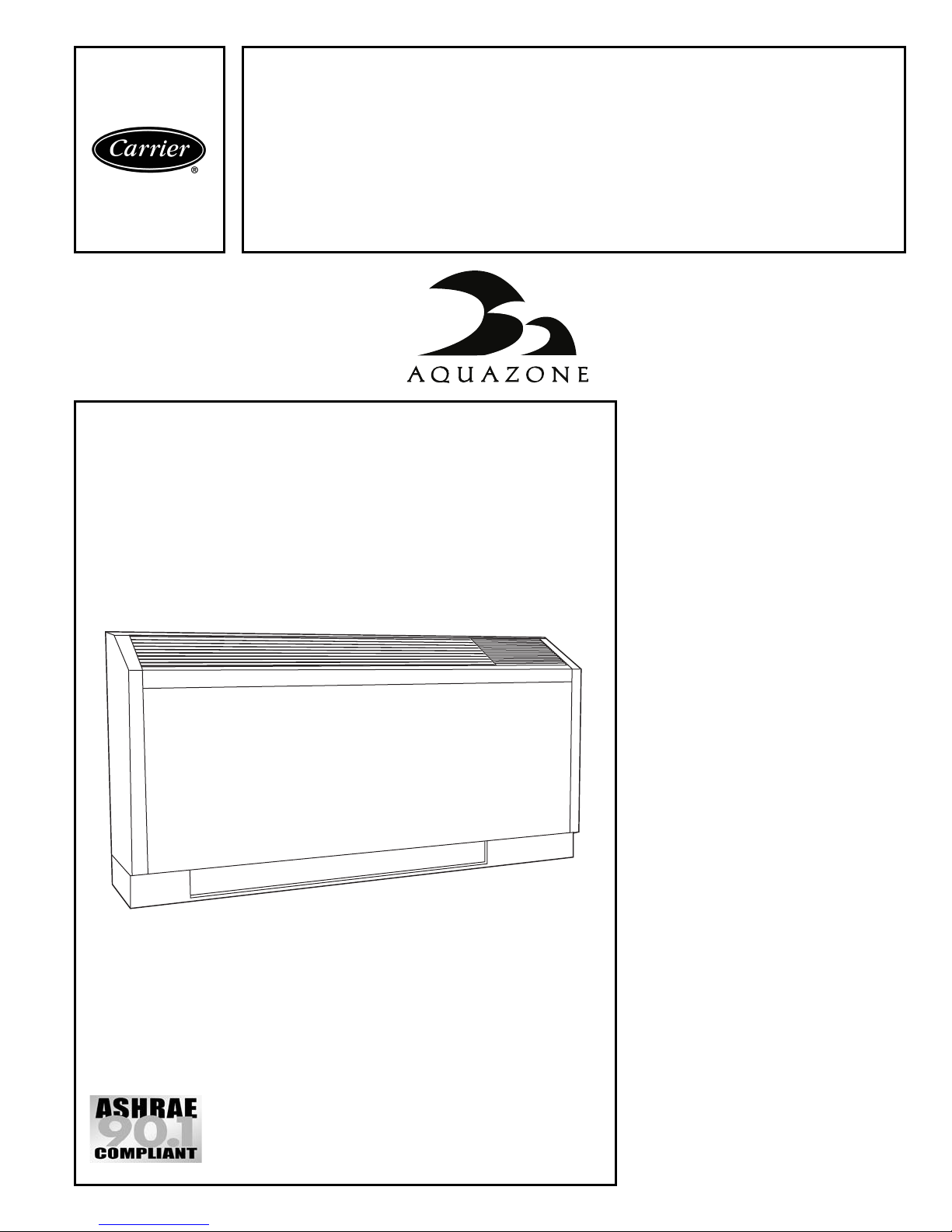
Product
Data
50KQA, KQD
Console Water Source Heat Pumps
1
/2 to 11/2 Nominal Tons
TM
Single-Package Console Water
Source Heat Pump with selfcontained line voltage thermostats.
• Wide application use with operating
temperature range from 40 F to
100 F
• Thermostatic expansion valve
(TXV) provides efficient and reliable
refrigerant flow
• Spring mounted compressors for
quiet operation
• Sloped top cabinet with powder
paint finish
• Right or left hand piping connection
• Multiple unit-mounted and remote
thermostat options
• Adaptable cabinet and subbase
configurations
• Factory-mounted flow regulators and
control valves for easy installation
• Flexible and reliable controls
accommodate all systems
Copyright 2003 Carrier Corporation Form 50KQ-6PD
Features/Benefits
Carrier’s Aquazone™
console water source heat
pumps are a flexible,
attractive alternative for all
finished interior space, under
window style installations.
Operating efficiency
Carrier Aquazone water source heat
pumps (WSHP) are designed for quality and performance excellence over
their lifetime. Models offer cooling
EERs (Energy Efficiency Ratio) to
12.8, and heating COPs (Coefficient
of Performance) to 4.6, which are
among the highest in the industry.
Quiet operation
The Carrier Console WSHP provides
exceptionally quiet operation for maximum comfort.
Page 2
Design flexibility
Aquazone™ Console WSHP units are
offered in 5 capacity sizes and in 3 different voltages to meet individual
zone needs efficiently and effectively.
Standard and Low temperature units
are available to suit a variety of application requirements.
Safe, reliable operation
Standard safety features include: high
and low pressure monitoring and field
selectable water and air coil freeze protection sensing. All safety controls may
be reset at the thermostat. Each unit is
tested and run at the factory to assure
proper operation of all components
and safety switches.
All components are carefully
designed and selected for endurance,
durability, and carefree day-to-day
operation.
The water-to-refrigerant heat
exchanger has copper inner and steel
outer tubing which is painted on the
outside to provide corrosion resistance
protection. Cupronickel heat exchangers are available and should be used on
all open loop applications.
Units are ARI (Air Conditioning &
Refrigeration Institute) Standard
320-93 certified and UL (Underwriters’ Laboratories) and CSA (Canadian
Standards Association) listed.
Installation ease
The unit is packaged for simple, low
cost handling, with minimal time required for installation. The console unit
arrives at the jobsite fully assembled to
minimize installation time and reduce
installation cost. All units are pre-wired
and factory charged with refrigerant.
Water connections are available in a
variety of configurations direct from
the factory. The standard configuration
5
is
/8 in. OD Sweat connections for
maximum flexibility in the field. Both
FPT and MPT are available as factoryinstalled options to improve installation
efficiency. Additionally, factoryinstalled motorized water shutoff
valves are available for use on energy
conserving systems employing a
variable pumping technique.
The standard electrical connections
are made quickly and directly to a power distribution terminal block. To further improve installation efficiency,
fused or unfused disconnect switch,
as well as a 20 amp plug and cord are
available as factory-installed options.
5
A
/8 in. ID vinyl condensate connection is provided for connection to
the field-installed condensate line.
Compact cabinet design dimensions are 10 in. deep, 48 in. wide
and 24 in. tall (with 3 in. subbase).
For flexibility, the controls can be
mounted on the top right or left side.
Additionally, the sloped top design
discourages the use of the unit as a
shelf or coffee holder, preventing air
blockage and any spills from damaging
the unit.
No-fuss maintenance and
serviceability
Regular maintenance or service to the
console WSHP units require little time.
Large service access panels enable
quick inspection for problem solving
and the control box swings down for
easy access to the controls.
Fan motor sleeve bearings are
permanently lubricated for worry-free
performance. If the unit does require
service, an easily removable cabinet
and slide out fan section makes access
simple.
Refrigerant circuit protection is designed to result in fewer service calls.
Units are equipped with easily accessible service access ports on both the
suction and the discharge refrigerant
lines for on-site testing and environmentally correct refrigerant recovery.
Filter racks provide easy filter access
for cleaning.
Maximum control flexibility
Aquazone water source heat pumps
provide reliable control operation using
a standard microprocessor board. Flexible alternatives for many direct digital
control (DDC) applications include the
Carrier Comfort Network (CCN) and
open protocol systems.
Carrier’s Aquazone standard unit
solid-state control system, the Complete C, provides control of the unit
compressor, reversing valve, fan, safety
features, and troubleshooting fault indication features. The Complete C is
one of the most user friendly, low cost,
and advanced control boards found in
the WSHP industry. Many features are
field selectable to provide the ultimate
in field installation flexibility. The
overall features of this standard control
system include:
50VA transformer —
accommodating accessory loads.
Assists in
Table of contents
Features/Benefits . . . . . . . . . . . . . . . . . . . . . . . . . . . . . . . . . . . . . . . . . . .1-3
Model Number Nomenclature . . . . . . . . . . . . . . . . . . . . . . . . . . . . . . . . . . . 4
ARI Capacity Ratings . . . . . . . . . . . . . . . . . . . . . . . . . . . . . . . . . . . . . . . . . 4
Physical Data . . . . . . . . . . . . . . . . . . . . . . . . . . . . . . . . . . . . . . . . . . . . . . . 5
Options and Accessories . . . . . . . . . . . . . . . . . . . . . . . . . . . . . . . . . . . . . .6-8
Base Unit Dimensions . . . . . . . . . . . . . . . . . . . . . . . . . . . . . . . . . . . . . .9-13
Selection Procedure . . . . . . . . . . . . . . . . . . . . . . . . . . . . . . . . . . . . . . .14,15
Performance Data . . . . . . . . . . . . . . . . . . . . . . . . . . . . . . . . . . . . . . . .16-21
Application Data . . . . . . . . . . . . . . . . . . . . . . . . . . . . . . . . . . . . . . . . .22-24
Electrical Data . . . . . . . . . . . . . . . . . . . . . . . . . . . . . . . . . . . . . . . . . . . . . 25
Typical Wiring Schematics . . . . . . . . . . . . . . . . . . . . . . . . . . . . . . . . . .26-31
Typical Piping and Wiring . . . . . . . . . . . . . . . . . . . . . . . . . . . . . . . . . . .32-34
Guide Specifications . . . . . . . . . . . . . . . . . . . . . . . . . . . . . . . . . . . . . . .35-37
2
Page
NRTL/C
NERGY STA R
As an E
Carrier Corporation has determined that this product meets
NERGY STA R
the E
for energy efficiency.
® Partner,
guidelines
Page 3

Features/Benefits (cont)
Anti-short cycle timer —
minimum off time to prevent the unit
from short cycling. The 5-minute timer
energizes when the compressor is
deenergized, resulting in a 5-minute
delay before the unit can be restarted.
Random start relay —
random delay in energizing each different WSHP unit. This option minimizes
peak electrical demand during start-up
from different operating modes or after
building power outages.
High and low pressure refrigerant
protection —
unreliable unit operation and prevents
refrigerant from leaking.
Condensate overflow sensor —
Electronic sensor mounted to the drain
pan. When condensate pan liquid
reaches an unacceptable level, the unit
is automatically deactivated and placed
in a lockout condition. The sensor
recognizes thirty continuous seconds
of overflow as a fault condition.
High and low voltage protection —
Safety protection for excessive or low
voltage conditions.
Automatic intelligent reset —
shall automatically restart 5 minutes
after shutdown if the fault has cleared.
Should a fault occur 3 times sequentially, lockout will occur.
Accessory output —
such as variable speed pumping, a
24 V output cycles a motorized water
valve or damper actuator with
compressor.
Performance Monitor (PM) —
Unique feature monitors water temperatures to warn when the heat pump
is operating inefficiently or beyond
typical operating range. A field selectable switch initiates a warning code on
the unit display.
Safeguards against
Provides a
Ensures a
Unit
In applications
Water coil freeze protection
(selectable for water or antifreeze) —
water and water/glycol solution systems initiates a fault when temperatures exceed the selected limit for
30 continuous seconds.
Air coil freeze protection (check
filter operation) —
switch for assessing excessive filter
pressure drop initiates a fault when
temperatures exceed the selected limit
for 30 continuous seconds.
Alarm relay setting —
24 V or pilot duty dry contact provides
remote alarm activation.
Electric heat option —
vided on the controller for operating
two stages of emergency electric heat.
Service test mode with diagnostic
LED (light-emitting diode) —
mode allows service personnel to
check the operation of the WSHP and
control system efficiently. Upon entering test mode, time delays speed up,
and the Status LED flashes a code
indicating the last fault. This mode
provides easy fault diagnosis; based on
the fault code the status LED flashes,
Carrier provided troubleshooting tables
provide easy reference to typical
problems.
LED visual output —
indicates high pressure, low pressure,
low voltage, high voltage, air/water
freeze protection, condensate overflow, and control status.
Field selectable switch for
Field selectable
Selectable
Output pro-
An LED panel
Carrier PremierLink™ controller adds reliability, efficiency,
and simplification
The PremierLink direct digital controller can be ordered as a factory-installed
option. Designed and manufactured
Tes t
exclusively by Carrier, the controller
can be used to actively monitor and
control all modes of operation as well
as monitor the following diagnostics
and features: unit number, zone tem-
perature, zone set point, zone humidity
set point, discharge air temperatures,
fan status, stages of heating, cooling
stages, outdoor-air temperature,
leaving-air temperature, leaving water
temperature, alarm status, and alarm
lockout condition.
This controller has 38.4K baud
communications capability and is compatible with ComfortLink™ Controls,
CCN and ComfortVIEW™ Software.
The Scrolling Marquee and Navigator
are optional tools used for programming and monitoring the unit for optimal performance. Adding the Carrier
CO
sensor in the conditioned space
2
provides ASHRAE 62-99 compliance
and Demand Control Ventilation
(DCV). A DCV control strategy is especially beneficial for a water source heat
pump system to minimize the energy
used to condition ventilation air. In
combination with energy efficient
Aquazone units, DCV may be the most
energy efficient approach ever developed for a water source heat pump
system.
The PremierLink peer-to-peer,
Internet ready communicating control
is designed specifically for Constant
Volume and Variable Volume Temperature applications. This comprehensive
controls system allows water source
heat pumps to be linked together, creating a fully functional HVAC (heating,
ventilation, and air conditioning) automation system.
3
Page 4
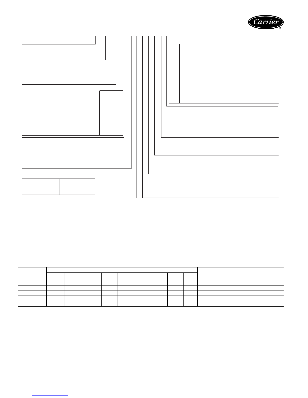
Model number nomenclature
50 KQA 007 L C F 3 0 1 A A
50 – Carrier Prefix
Series
KQA – Standard Temperature Range (60 to 95 F)
KQD – Low Temperature Range (40 to 110 F)
Size – Tons
007 – 1/2
009 – 3/4
012 – 1
015 – 1-1/4
019 – 1-1/2
Water Connections/Valve Options*
No Valve Options L R
Standard Water Control Valve† AJ
High MOPD Water Control Valve** B K
Autoflow Regulator Sized for 2.5 GPM per Ton C M
Autoflow Regulator Sized for 3.0 GPM per Ton D N
Standard Control Valve with 2.5 GPM/Ton Regulator E P
Standard Control Valve with 3.0 GPM/Ton Regulator F Q
High MOPD Control Valve with 2.5 GPM/Ton Regulator G S
High MOPD Control Valve with 3.0 GPM/Ton Regulator H T
Controls
A – Manual Changeover with Complete C Microprocessor Board
B – Manual Changeover with Deluxe D Microprocessor Board
C – Automatic Changeover with Complete C Microprocessor Board
D – Automatic Changeover with Deluxe D Microprocessor Board
P – PremierLink™ DDC Control††
R – Remote Thermostat with Complete C
S – Remote Thermostat with Deluxe D
Heat Exchanger
Connection Copper Cupronickel
1/2″ Female Pipe Thread F G
1/2″ Sweat S (Std) T
1/2″ Male Pipe Thread M N
Connection Side
Left Right
Cabinet & Subbase Options
Option Cabinet Subbase
A Bottom Return 3″ Subbase
B Bottom Return 3″ Subbase w/Motorized Damper
C Bottom Return 5″ Subbase w/Motorized Damper
D Bottom Return No Subbase
E Bottom Return, Control Door Lock 3″ Subbase
F Bottom Return, Control Door Lock 3″ Subbase w/Motorized Damper
G Bottom Return, Control Door Lock 5″ Subbase w/Motorized Damper
H Bottom Return, Control Door Lock No Subbase
J Front Return No Subbase
K Front Return, Control Door Lock No Subbase
L No Cabinet 3″ Subbase
M No Cabinet 3″ Subbase w/Motorized Damper
N No Cabinet 5″ Subbase w/Motorized Damper
P No Cabinet No Subbase
Q No Cabinet 5″ Subbase
R Bottom Return 5″ Subbase
S Bottom Return, Control Door Lock 5″ Subbase
Power Connection
A – Field Connected, Hard Wire
B – 20A Plug
D – Disconnect Switch & 15A Fuse
F – Disconnect Switch, Non-Fused
H – 20A Plug, Cord Receptacle, Disconnect Switch, 15A Fuse
K – 20A Plug, Cord Receptacle, Disconnect Switch, No Fuse
Packaging
1 – Domestic
Revision Code
0 – Current Revision – Water Circuit Options
Voltage
1 – 115V/1 Ph/60 Hz***
3 – 208/230V/1 Ph/ 60 Hz
4 – 265V/1 Ph/60 Hz†††
LEGEND
Cv —
MOPD —
Coefficient of Velocity
Maximum Operating Pressure Differential
*Determined by looking at the unit from the front.
†Cv of 3.5 and MOPD of 20 psi.
**Cv of 2.5 and MOPD of 50 psi.
††Available with Complete C only.
***Sizes 007, 009, and 012 only.
†††20A plug and cord are not available in 265V units.
ARI* capacity ratings
UNIT 50KQ
007
009
012
015
019
TC TSC THR kW EER TC THA kW COP
6,800 5,032 8,500 0.531 12.8 8,600 6,958 0.548 4.6 280 1.7 2.3
9,000 6,667 11,500 0.744 12.1 11,600 9,215 0.791 4.3 280 2.3 4.2
11,800 8,160 15,000 0.922 12.8 14,000 10,797 1.052 3.9 375 3.0 9.4
15,000 10,959 19,000 1.200 12.5 17,100 13,395 1.222 4.1 400 3.8 3.0
17,600 12,361 22,500 1.467 12.0 21,000 16,058 1.620 3.8 430 4.5 4.2
LEGEND
CFM —
COP —
db —
EER —
GPM —
kW —
TC —
THA —
THR —
TSC —
wb —
Cubic Feet Per Minute
Coefficient of Performance
Dry Bulb Temperature
Energy Efficiency Ratio
Gallons Per Minute
Total Power Input (Kilowatt Hours)
Total Capacity (Btuh)
Total Heat of Absorption (Btuh)
Total Heat of Rejection (Btuh)
Total Sensible Capacity (Btuh)
Wet Bulb Temperature
*Air Conditioning & Refrigeration Institute.
COOLING HEATING
AIRFLOW
CFM
NOTES:
1. Ratings are in accordance with ARI Standard 320-93.
2. Cooling Standard: 80 F db, 67 F wb indoor entering air temperature,
85 F entering water and 95 F leaving water temperatures.
3. Heating Standard: 70 F db indoor entering air temperature, and 70 F
entering water temperature.
WATER
FLOW RATE
GPM
PRESSRUE
DROP
ft wg
4
Page 5
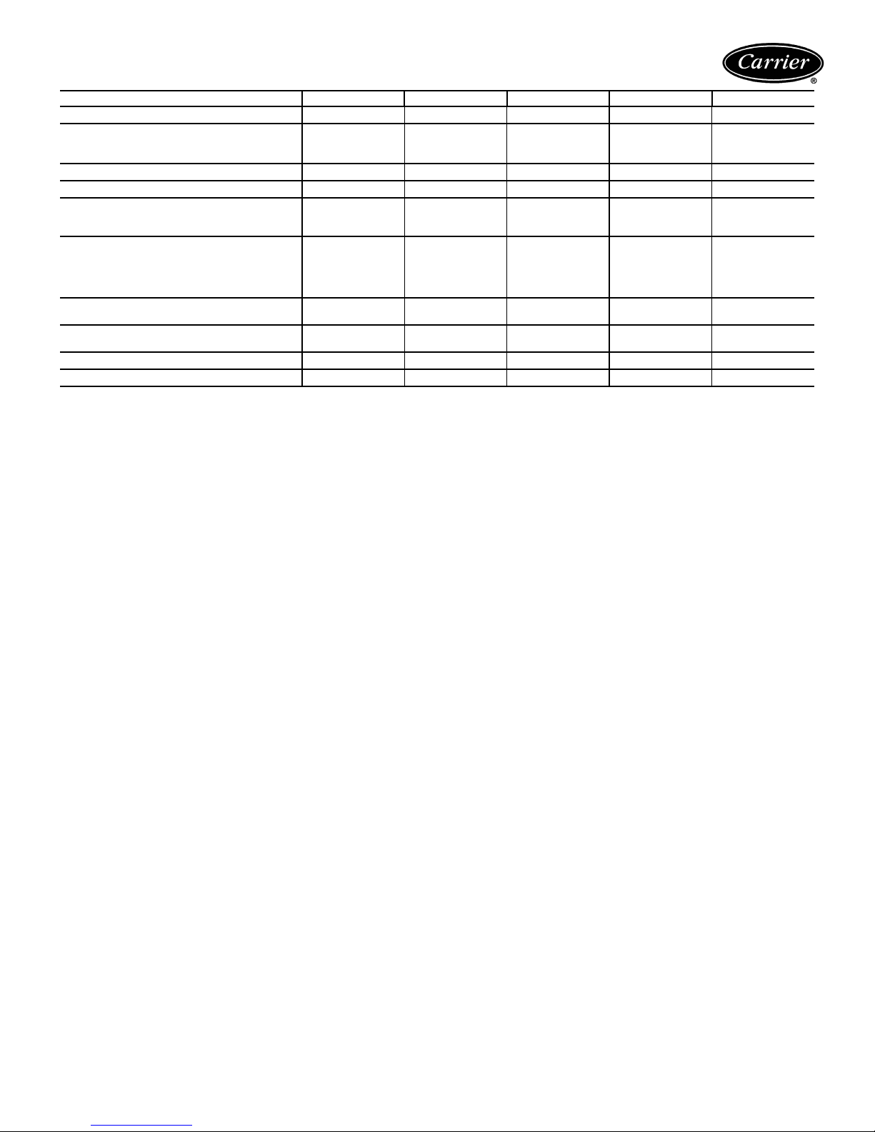
Physical data
BASE UNIT 50KQA, KQD 007 009 012 015 019
NOMINAL CAPACITY (tons)
BLOWER
Motor Horsepower
Wheel Size D x W (in.) 2 each
FILTER SIZE (in.) Bottom Return
FILTER SIZE (in.) Front Return
UNIT WEIGHT (lb)
Shipping
Operating
REF. TO AIR HEAT EXCHANGER
Face Area (sq. ft)
No. of Rows Deep
Copper Tube Size O.D. (in.)
No. of Fins/in.
REFRIG. CHARGE (R-22)/CKT (oz.)
No. of Circuits
UNIT CABINET W/STAND. SUBBASE
W x H x D (in.)
WATER IN/OUT SIZE O.D. SWEAT (in.)
CONDENSATE SIZE I.D. VINYL (in.)
1
51/4 x 61/
8 x 29
7 x 29
158
151
1.44
1
3
13
16
/
/
20
1
1
2
/
1
2
/2 x 3/
/2 x 1/
8
4
8
8
3
/
4
1
/
20
51/4 x 61/
8 x 291/2 x 3/
7 x 291/2 x 1/
162
154
1.44
2
3
/
8
13
16
1
11
1
/
15
4
8
8
51/4 x 61/
8 x 291/2 x 3/
7 x 291/2 x 1/
4
8
8
172
164
1.44
3
3
/
8
13
21
1
1
/
4
1
/
15
51/4 x 61/
8 x 291/2 x 3/
7 x 291/2 x 1/
178
168
1.81
3
3
/
8
13
23
1
11/
2
1
/
6
4
8
8
51/4 x 61/
8 x 291/2 x 3/
7 x 291/2 x 1/
183
174
1.81
3
3
/
8
13
22
1
48 x 24 x 10 48 x 24 x 10 48 x 24 x 10 48 x 24 x 10 48 x 24 x 10
5
/
8
5
/
8
5
/
8
5
/
8
5
/
8
5
/
8
5
/
8
5
/
8
5
/
8
5
/
8
4
8
8
5
Page 6
Options and accessories
Factory-installed options
Cupronickel heat exchangers
corrosion protection for applications such as open tower,
geothermal, etc. Consult the water quality guidelines for
proper application and selection of this option.
Thermostat options
Changeover (MCO) or Auto Changeover (ACO) thermostat. The temperature set point knob and push button
switches for fan speed and cool/heat mode (MCO) selection are conveniently located on the top. The thermostat
senses the return-air temperature. The thermostat sends
the appropriate signal to the controller for cooling or heating mode of operation.
Options R and S allow connection to a remote wallmounted thermostat. The Complete C controller requires a
heat pump thermostat. The Deluxe D controller can be
configured for heat pump or heat/cool thermostat.
Cabinet options
added security. A bottom or front return with left or right
hand configurations for ease of installation. Available with
3 or 5 in. subbase, with or without motorized damper.
Motorized fresh air damper
thermostat. Opens when LOW or HIGH fan speed selections are made from the push button switches. When
STOP or FAN ONLY selections are made the spring return
on the damper motor closes the damper. With remote thermostat the motorized fresh air damper opens when the fan
is running.
Piping connections
or left hand side of the unit, for easy installation. Orientation is determined by facing the unit from the front side.
Automatic flow regulators
2.5 or 3.0 gpm per ton automatic flow regulating valves
for easier install
Two-way motorized control valve
a copper or cupronickel heat exchanger for applications
involving open type systems or variable speed pumping.
This valve will slowly open and close in conjunction with the
compressor operation to shut off or turn on water to the
unit. Standard and high maximum operating pressure differential (MOPD) valve options are available for maximum
installation flexibility. Standard two-way valve performance
includes Cv of 3.5 and MOPD of 20 psi. High MOPD valve
performance includes Cv of 2.5 and MOPD of 50 psi.
Deluxe D control system
as the Complete C while incorporating additional flexibility
and functions to include:
Thermostat input capabilities
shutdown mode and night setback with override (NSB)
potential. Night setback from low temperature thermostat
with 2-hour override is initiated by a momentary signal
from the thermostat.
Compressor relay staging
(units with 2 compressors and 2 D controls) or in master/
slave applications.
ation.
include a unit mounted Manual
include a locking control panel for
can be provided on either the right
— Used with dual stage units
are available for higher
with the unit-mounted
include internally mounted
can be provided with
provides the same functions
— Accommodate emergency
Boilerless electric heat control system
changeover to electric heat at low loop water temperature.
Intelligent reversing valve operation
valve operation for extended life and quiet operation.
Thermostat type select (Y, O or Y, W)
work and select heat pump or heat/cool thermostats (Y, W).
Reversing valve signal select (O or B)
for heat pump O/B thermostats.
Dehumidistat input
dehumidification operation.
Multiple units on one thermostat/wall sensor
for communication for up to three heat pumps on one
thermostat.
Boilerless changeover temperature
boilerless changeover temperature set point.
Accessory relays
cations including fan and compressor cycling, digital night
setback (NSB), mechanical night setback, water valve operation, and outside air damper operation.
Night low limit
either the push button switches, remote thermostat or the
energy management system, it is possible that the space
temperature could drop uncontrollably. The Night Low
Limit feature, with Deluxe D controller, helps maintain the
space temperature at a level that is the best compromise
between energy consumption and a safe space temperature. A thermostat located near the return air filter
activates the blower and compressor operation when the
space temperature falls below 50 F. When return air temperature is raised above 55 F the compressor and blower
stop.
Override function
units operating in occupied/unoccupied mode under the
control of an external timeclock or an energy management
system. A contact closure from the timeclock or energy
management system shorts the NSB and C terminal on the
Deluxe D controller signaling an unoccupied mode.
For units with the unit-mounted thermostat, pressing
override switch (located under control access door) will
override the unoccupied mode and allow the occupied
mode of operation to continue for a period of two hours.
The units with the remote wall-mounted thermostat
require a digital thermostat with the override function. In
unoccupied mode an accessory relay is energized on the
Deluxe D controller. The NO/NC contacts of the relay can
be used as appropriate input to the digital thermostat to
signal occupied/unoccupied mode. The thermostat selects
cooling/heating set points based on occupied/unoccupied
mode.
PremierLink™ controller
Comfort Network (CCN) and other building automation
systems (BAS). This control is designed to allow users the
access and ability to change factory-defined settings thus
expanding the function of the standard unit.
— Provides operation of fan control for
— Allow configuration for multiple appli-
— If the unit operation is turned OFF from
— An Override function is available for
is compatible with the Carrier
— Allows automatic
— Minimizes reversing
— Provides ability to
— Provides selection
— Provides
— Provides selection of
6
Page 7
50KQA,KQD CONTROL OPTIONS TABLE
OPTION CONTROLLER THERMOSTAT FUNCTIONS TRANSFORMER
A
B
C
D
P
R
S
LEGEND
Auto Changeover
ACO —
MCO —
Manual Changeover
Complete C MCO — 50 VA
Deluxe D MCO NIGHT LOW LIMIT 2-HR OVERRIDE 75 VA
Complete C ACO — 50 VA
Deluxe D ACO NIGHT LOW LIMIT 2-HR OVERRIDE 75 VA
Complete C with PremierLink™ LINKAGE DDC SYSTEM 50 VA
Complete C REMOTE — 50 VA
Deluxe D REMOTE NIGHT LOW LIMIT2-HR OVERRIDE 75 VA
Field-installed accessories
Carrier’s line of Aquazone™ thermostats (used with
remote thermostat units)
functional, accommodating stand-alone water source heat
pump installations.
Programmable 7-day thermostat
2-stage cool, auto changeover, 7-day programmable with
copy command, 4 settings per day, fully electronic, 24 vac,
backlit LCD, keypad lockout, no batteries required,
5-minute compressor protection, NEVERLOST™ memory,
3 security levels, temperature display in degrees F or C.
Programmable 7-day light-activated thermostat
same features as the 7-day programmable thermostat and
includes occupied comfort settings with lights on, unoccupied energy savings with lights off.
Programmable 7-day flush-mount thermostat
same features as the 7-day programmable thermostat and
includes locking coverplate with tamper proof screws, flush
to wall mount, holiday/vacation programming, set point
limiting, dual point with adjustable deadband, O or B terminal, and optional wall or duct-mounted remote sensor.
Programmable 5-day thermostat
2-stage cool, auto changeover, 5-minute built-in compressor protection, locking cover included, temperature display
in degrees F or C, keypad lockout, backlit display, 5-1-1
programming, O or B terminal, dual set point with adjustable deadband, configurable display, self-prompting program, 4 settings per day.
Non-programmable thermostat
2 cool stages, auto changeover, 5-minute built in compressor protection, locking cover included, temperature display
in degrees F or C, keypad lockout, large display, back-lit
display, O or B terminal, dual set point with adjustable
deadband, backplate with terminals.
Aquazone system control panel
programmed, easy to use, Carrier Comfort Controller set
up for a WSHP system.
• Coordinates, monitors, and controls all WSHP units
and ancillary equipment including cooling towers, boilers, and system pumps.
• 50RLP model nomenclature is used to customize the
panel to control all WSHP system requirements.
• Panel can be ordered to include 2, 4, 6, or 8 stages of
system heat rejection.
• Panel can be ordered to include 2, 4, 6, or 8 stages of
system heat addition.
are both attractive and multi-
— Offers 2-stage heat,
— Offers
— Offers
— Offers 2-stage heat,
— Offers 2 heat stages,
includes a pre-
• Panel can be ordered with unique WSHP zone operation
capabilities for stand alone systems (i.e., non-communicating)
to control 10 or 18 zones of WSHP units.
• Panel can be ordered to control variable frequency cooling tower fan operation.
• System pumping operation can be configured for start/
stop, lead/lag, or variable frequency pump operation.
• Direct Digital Control compatible using the Carrier
Comfort Network (CCN) and WSHP units utilizing
PremierLink CCN controllers.
Fire-rated hoses
are 2 ft long and have a fixed MPT on
one end and a swivel with an adapter on the other end.
Hose kits are provided with both a supply and return hose
and can be either stainless steel or galvanized. Five sizes
are available (
Ball valves (brass body)
1
/2, 3/4, 1, 11/4, 11/2 in.).
used for shutoff and balancing
water flow. Available with memory, memory stop, and
pressure temperature ports. UL-listed brass body, ball and
stem type with Teflon seats and seals. Five sizes are avail-
1
able (
/2, 3/4, 1, 11/4, 11/2 in.).
Y strainers (bronze body)
are “Y” type strainers with a
brass cap. Maximum operating pressure rating of
450 psi. Strainer screen made of stainless steel. Available
with blow down valves. Five sizes are available (
1
/4, 11/2 in.).
1
Solenoid valves (brass body)
offer 3.5 watt coil,
1
/2, 3/4, 1,
24 volt, 50/60 Hz, 740 amps inrush, .312 amps holding.
Slow operation for quiet system application. Five sizes are
available (
Hose kit assemblies
1
/2, 3/4, 1, 11/4, 11/2 in.).
provide all the necessary components to hook up a water-side system. Supply hose includes
a ported ball valve with pressure temperature (P/T) plug
ports, flexible stainless steel hose with swivel and nipple.
Return hose includes a ball valve, preset automatic balancing valve (gpm) with two P/T ports, flexible stainless steel
hose with a swivel and nipple, balancing valve, and lowpressure drop water control valve.
Remote sensors
are available for Aquazone flush mount
thermostats. Sensors are available for wall (wired and wireless) or duct mounted applications.
PremierLink™ accessories
are available to provide a
fully integrated WSHP DDC system. Accessories include
supply air temperature sensors (with override and/or setpoint adjustment), communicating room sensors, CO
sen-
2
sors (for use in demand control ventilation), and linkage
thermostats (to control multiple units from one thermostat).
7
Page 8
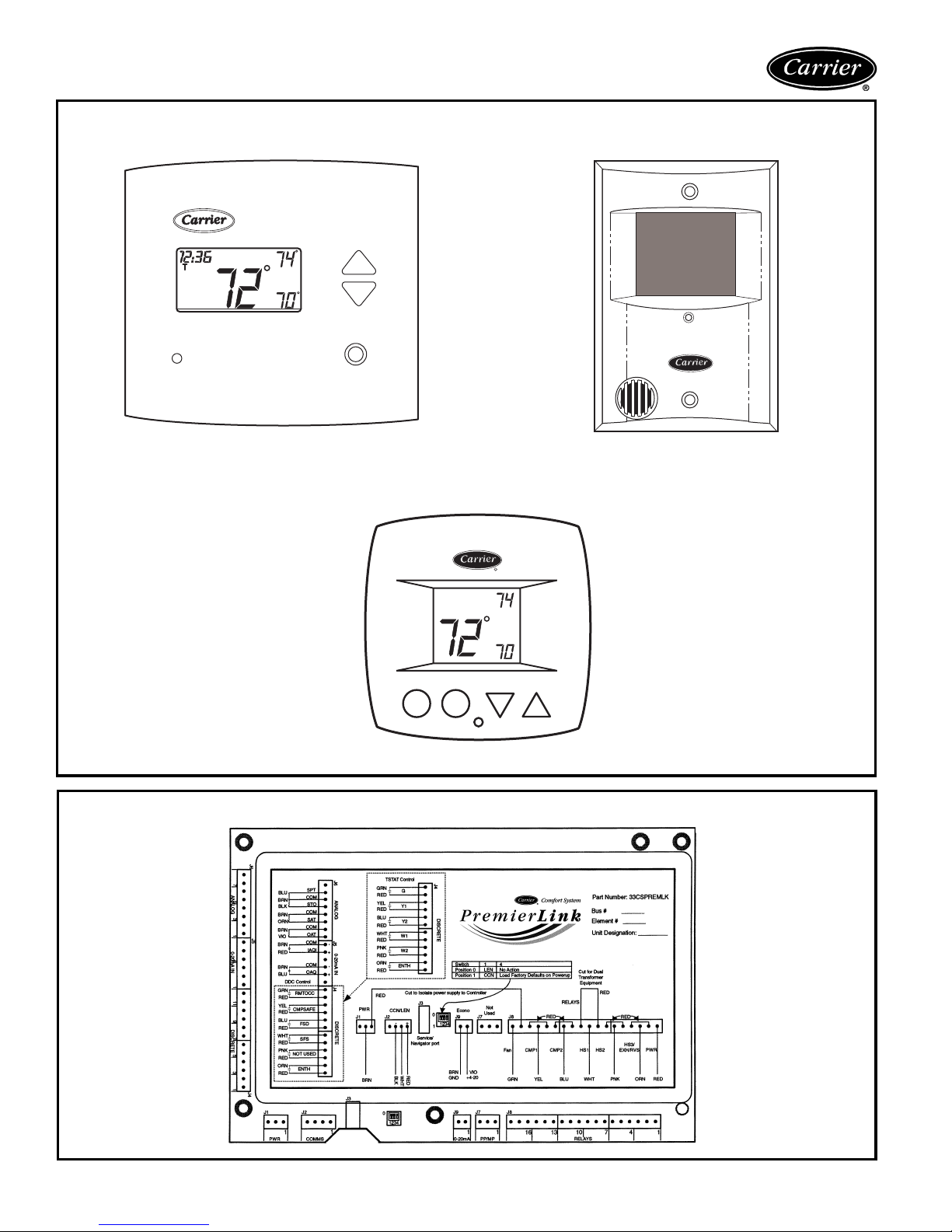
Options and accessories (cont)
CARRIER AQUAZONE™ THERMOSTATS
(FOR USE WITH REMOTE THERMOSTAT UNITS)
Carrier
®
Pm
AUTO
7-DAY PROGRAMMABLE/LIGHT-ACTIVATED
PROGRAMMABLE
COOL
HEAT
R
COOL
AUTO
HEAT
7-DAY PROGRAMMABLE FLUSH MOUNT
5-DAY PROGRAMMABLE/NON-PROGRAMMABLE
PREMIERLINK™ COMMUNICATING CONTROL
8
Page 9
Base unit dimensions
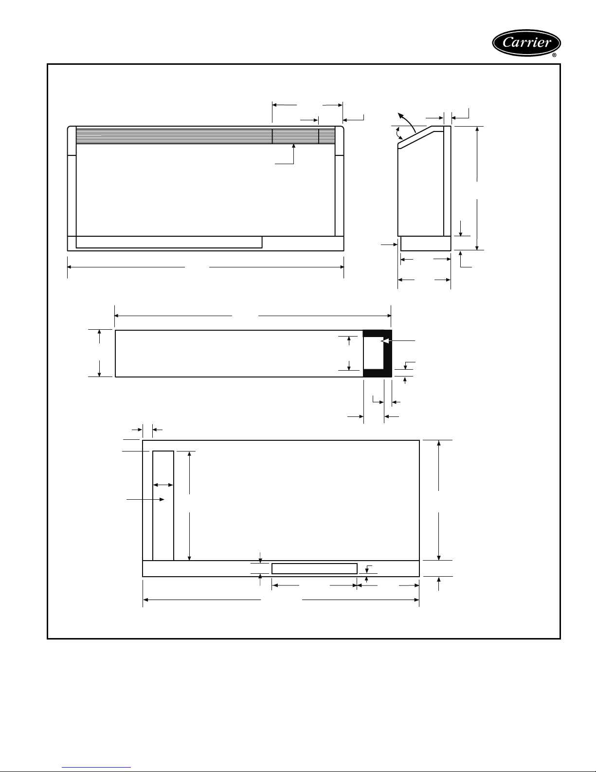
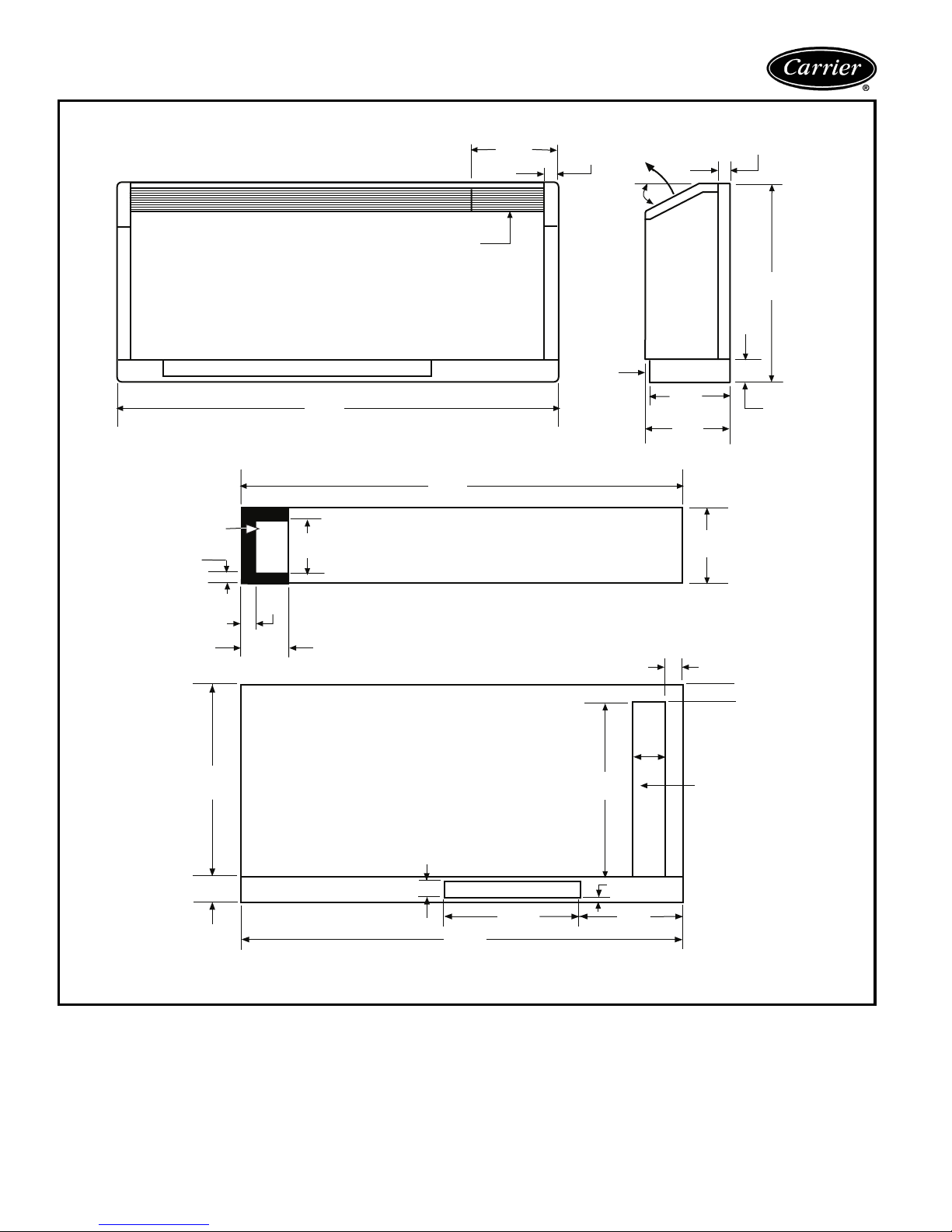
50KQA,KQD BOTTOM RETURN CABINET DIMENSIONS — RIGHT HAND PIPING
9.5
(241)
AIR INLET AREA
(1219)
FRONT VIEW
Control Access Door
48
48
(1219)
16
(406)
8
(203)
5
(127)
Air
Inlet
1.5
(38)
Discharge
Air
30°
9.5
(241)
10
(254)
R.H. Pipe &
Electric Area
0.75
(19)
1.5
(38)
(610)
24
3
(76)
1(25)
1 (25)
4.5
(114)
REAR
ACCESS
NOTE: All measurements in inches. Measurements in parentheses are in millimeters.
20
(508)
REAR VIEW
1.63
(41)
DAMPER OPENING*
48
(1219)
11.75
(298)
3.5
0.81
(21)
9.75
(248)
(89)
*Optional 5-in. (127) sub-
base will increase damper
opening to 3.63-in. (92)
21
high and increase overall
(533)
unit height by 2 in. (51).
3
(76)
9
Page 10
Base unit dimensions (cont)
50KQA,KQD BOTTOM RETURN CABINET DIMENSIONS — LEFT HAND PIPING
Control Access Door
12.5
(318)
1.5
(38)
Discharge
Air
30°
1.5
(38)
24
(610)
L.H. Pipe &
Electric Area
0.75
(19)
21
(533)
AIR INLET AREA
48
(1219)
FRONT VIEW
8
(203)
1.5
(38)
3.5
(89)
48
(1219)
REAR VIEW
Air
Inlet
20
(508)
4.5
(114)
9.5
(241)
10
(254)
9.5
(241)
1(25)
1 (25)
REAR
ACCESS
3
(76)
3
(76)
NOTE: All measurements in inches. Measurements in parentheses are in millimeters.
10
1.63
(41)
DAMPER OPENING*
48
(1219)
11.75
(298)
0.81
(21)
9.75
(248)
*Optional 5-in. (127) subbase
will increase damper opening
to 3.63-in. (92) high and
increase overall unit height by
2 in. (51).
Page 11
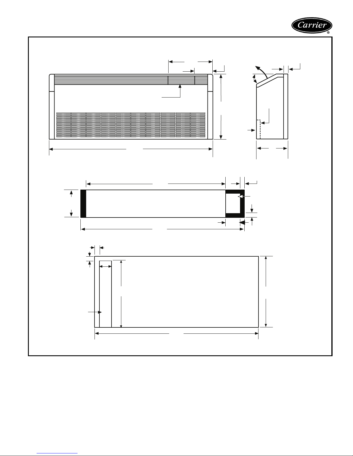
50KQA,KQD FRONT RETURN CABINET DIMENSIONS — RIGHT HAND PIPING
Air
Discharge
30°
Filter
Air
Inlet
Control Access Door
16
(406)
5
(127)
21
(533)
1.5
(38)
9.5
(241)
REAR
ACCESS
1
(25)
48
(1219)
FRONT VIEW
No damper available with front return option.
41.75
(1060)
BLOCK OFF PLATE ON
BOTTOM OF CHASSIS
48
(1219)
1 (25)
4.5
(114)
20
(508)
REAR VIEW
3.5
(89)
10
(254)
1.5
(38)
R.H. PIPE &
ELECTRIC AREA
0.75 (19)
21
(533)
NOTE: All measurements in inches. Measurements in parentheses are in millimeters.
48
(1219)
11
Page 12
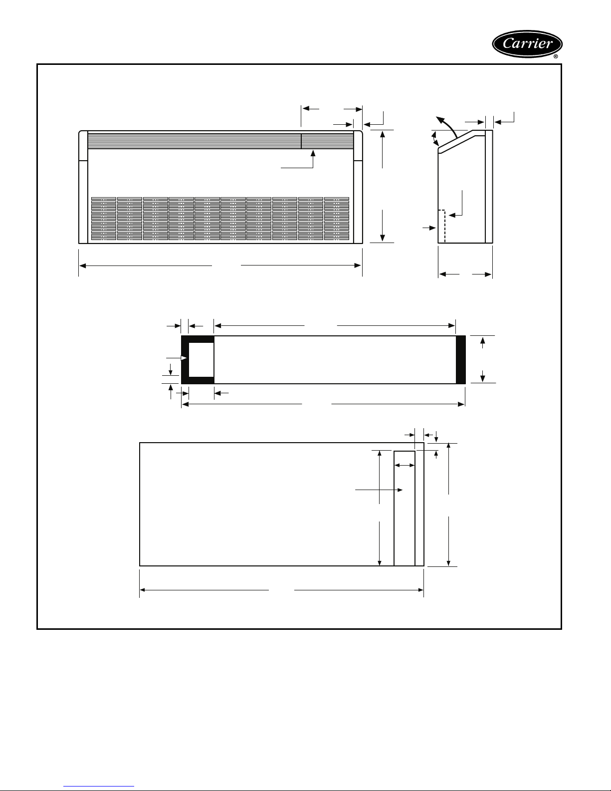
Base unit dimensions (cont)
50KQA,KQD FRONT RETURN CABINET DIMENSIONS — LEFT HAND PIPING
1.5 (38)
L.H. PIPE &
ELECTRIC AREA
(19)
0.75
12.5
(318)
Control Access Door
48
(1219)
FRONT VIEW
1.5
(38)
21
(533)
Inlet
No damper available with front return option.
41.75
(1060)
BLOCK OFF PLATE ON
BOTTOM OF CHASSIS
3.5
(89)
48
(1219)
Air
Discharge
30°
Air
1.5
(38)
Filter
10
(254)
9.5
(241)
REAR VIEW
48
(1219)
NOTE: All measurements in inches. Measurements in parentheses are in millimeters.
REAR
ACCESS
20
(508)
1 (25)
4.5
(114)
1
(25)
21
(533)
12
Page 13
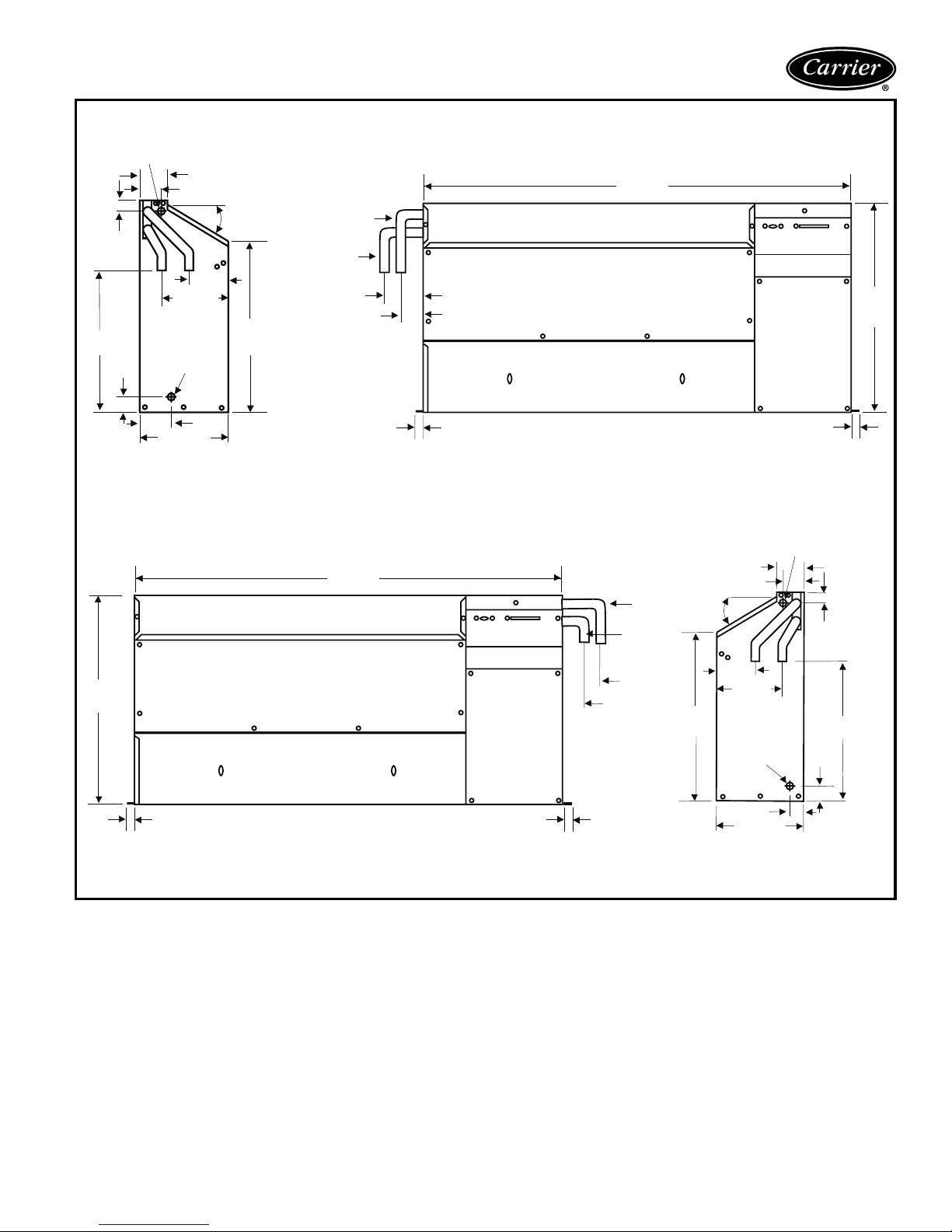
POWER
SUPPLY IN
1(25)
13.5
(343)
1.25
(32)
SIDE VIEW (LH)
20.5
(521)
2.125 (54)
6.5 (165)
CONDENSATE
RELIEF
3.2 (80)
9.5 (241)
0.75 (19)
3.375 (86)
30
4(182)
50KQA,KQD CHASSIS DIMENSIONS — 007, 009, 012, 015, 019
41
(1041)
°
16
(406)
WATER
OUT
WATER
IN
3.5
(89)
BLOWER DECK
2
(51)
BLOWER ACCESS PANEL
0.75 (19)
FRONT VIEW (LH)
41
(1041)
BLOWER DECK
BLOWER ACCESS PANEL
CONTROL BOX
COMPRESSOR
ACCESS
PANEL
0.75 (19)
WATER
2
(51)
WATER
OUT
3.5
IN
(89)
FRONT VIEW (RH)
3.375 (86)
(51)
2
30 °
(102)
4
(127)
5
16
(406)
CONDENSATE
RELIEF
1
(25)
9.5 (241)
SIDE VIEW (RH)
CONTROL BOX
COMPRESSOR
ACCESS
PANEL
0.75 (19)
POWER
SUPPLY IN
(38)
1.5
(25)
1
(330)
20.5
(521)
13
NOTE: All measurements in inches. Measurements in parentheses are in millimeters.
13
Page 14

Selection procedure (with 50KQA012 example)
I Determine the actual cooling and heating
loads at the desired dry bulb and wet bulb
conditions.
Assume cooling load at desired dry bulb 80 F and
wet bulb 66 F conditions are as follows:
Given:
Total Cooling (TC) . . . . . . . . . . . . . . .11,100 Btuh
Sensible Cooling (SC) . . . . . . . . . . . . .7,100 Btuh
Entering-Air Temperature db . . . . . . . . . . . . 80 F
Entering-Air Temperature wb . . . . . . . . . . . . .66 F
II Determine the following design parameters.
Determine entering water temperature, water flow
rate (GPM), airflow (CFM), water flow pressure drop
and design wet and dry bulb temperatures. Airflow
CFM should be between 300 and 450 CFM per ton.
Unit water pressure drop should be kept as close as
possible to each other to make water balancing easier. Enter the 50KQA012 Performance Data tables
and find the proper indicated water flow and water
temperature.
For example:
Entering Water Temp . . . . . . . . . . . . . . . . . 90 F
Water Flow (Based upon
12 F rise in temp) . . . . . . . . . . . . . . . . . 3.0 GPM
Airflow Cfm . . . . . . . . . . . . . . . . . . . . . 325 Cfm
III Select a unit based on total cooling and total
sensible cooling conditions. Unit selected
should be closest to but not larger than the
actual cooling load.
Enter tables at the design water flow and water
temperature. Read the total and sensible cooling
capacities.
NOTE: Interpolation is permissible, extrapolation is
not.
For example:
Enter the 50KQA012 Performance Table at design
water flow and water temperature. Read Total
Cooling, Sensible Cooling and Heat of Rejection
capacities:
Total Cooling . . . . . . . . . . . . . . . . . .11,500 Btuh
Sensible Cooling . . . . . . . . . . . . . . . . 7,300 Btuh
Heat of Rejection . . . . . . . . . . . . . . . 15,000 Btuh
NOTE: It is quite normal for water source heat
pumps to be selected on cooling capacity only since
the heating output is usually greater than the cooling
capacity. Heating capacity is selected based on
different entering water conditions than cooling
capacity.
IV Determine the correction factors associated
with the variable factors of dry bulb and wet
bulb using the Corrections Factor tables
found in this book.
Using the following formulas to determine the correction factors of dry bulb and wet bulb:
a) Corrected Total Cooling = tabulated total cooling
x wet bulb correction x airflow correction.
b) Corrected Sensible Cooling = tabulated sensible
cooling x wet/dry bulb correction x airflow
correction
V Determine entering air and airflow correction
using the Corrections Factor tables found in
this book.
The nominal airflow for 50KQA012 is 375 cfm.
The design parameter is 325 cfm.
325/375 = 87% of nominal airflow
Use the 87% row in the Nominal Cfm Correction
table.
The Entering Air Temperature wb is 66 F. Use the
66.2 F row in the Entering Air Correction table.
Using the following formulas to determine the cor-
rection factors of entering air and airflow correction:
Table Ent Air Airflow Corrected
Corrected
Total Cooling = 11,500 x 0.994 x 0.98 = 11,202
Corrected
Sensible Cooling = 7,300 x 1.030 x 0.964 = 7,248
Corrected
Heat of Rejection = 15,000 x 0.982 x 0.978 = 14,405
Compare the corrected capacities to the load
requirements established in Step I. If the capacities
are within 10% of the load requirements, the equipment is acceptable. It is better to undersize than
oversize as undersizing improves humidity control,
reduces sound levels and extends the life of the
equipment.
VI Water temperature rise calculation and
assessment.
Calculate the water temperature rise and assess the
selection using the following calculation:
Actual Temperature
Rise
Correction of Heat Rejection
=
GPM x 500
For example, using the Corrected Heat of Rejection
from the last step:
Actual Temperature
Rise
=
3.0 x 500
14,405
=9.6 F
If the units selected are not within 10% of the load
calculations, review what effect changing the GPM,
water temperature and/or airflow will have on the
corrected capacities. If the desired capacity cannot
be achieved, select the next larger or smaller unit
and repeat Steps I through VI.
14
Page 15

VII ARI/ISO/ASHRAE 13256-1 Conversion
Performance standard ARI/ISO/ASHRAE 13256-1
became effective on January 1, 2000 and replaced
the existing ARI Standards 320 Water-Loop Heat
Pumps (WLHP), 325 Ground-Water Heat Pumps
(GWHP), and 330 Ground-Loop Heat Pumps
(GLHP).
The ARI/ISO Standard incorporates a consistent
rating methodology for including fan and pump
energy for calculating cooling capacity, heating
capacity, and energy efficiency ratios (EER). This
simplifies the use of rating data for heat pump performance modeling in seasonal energy analysis calculations, and allows for direct rating comparisons
across applications.
a) ISO Capacity and Efficiency Equations
The following equations are used to calculate and
correct cooling capacity, heating capacity, and
respective EER:
ISO Cooling Capacity = (Cooling Capacity in
Btuh) + (Fan Power Correction in Watts x 3.412)
ISO Cooling EER = (ISO Cooling Capacity in
Btuh/3.412)/(Power Input in watts – fan power
correction in watts + pump power correction in
watts) = Watts/Watts
NOTE: Do not divide ISO Cooling Capacity by
3.412 to obtain Btuh/Watts.
ISO Heating Capacity = (Heating Capacity in
Btuh) – (Fan Power Correction in Watts x 3.412)
ISO Heating EER = (ISO Heating Capacity in
Btuh/3.412)/(Power Input in watts – fan power
correction in watts + pump power correction in
watts) = Watts/Watts
NOTE: Do not divide ISO Heating Capacity by
3.412 to obtain Btuh/Watts.
Refer to English to SI conversion table in this
book.
b) Identify the design conditions corrected for air and
water conditions.
Airflow Cfm = 325 Cfm
Water Flow
(Based upon 12 F rise in temp) = 3.0 GPM
External Static Pressure = 0.0 in. wg (non-ducted
application)
Water Pressure Drop = 1.3 ft of head
Power input = 1,030 watts
Cooling Capacity = 11,202 Btuh
c) Perform Fan Power Correction Adjustment
Use the following formula to calculate Fan Power
Correction:
Fan Power
Correction = (Cfm x 0.472) x (External Static
Pressure x 249)/300 = Watts
= (325 x 0.472) x (0 x 249)/300
= 0 Watts
d) Perform Pump Power Correction Adjustment
Use the following formula to calculate Pump
Power Correction:
Pump Power
Correction = (GPM x 0.0631) x (Pressure Drop
x 2,990)/300
= Watts
= (3 x 0.0631) x
(13 x 2,990)/300
=24.5 Watts
e) Perform capacity and EER calculations
Use the following formula to calculate capacity
and EER:
ISO Cooling
Capacity = (Cooling Capacity) + (Fan Power
Correction x 3.412)
= 11,202 + (0 x 3.412)
= 11,202 Btuh
f) Perform Corrections by using the ISO Equations
ISO EER = (ISO Cooling Capacity/3.412)/
(Power Input – Fan Power Correction + Pump Power Correction)
= Watts/Watts
NOTE: Do not divide ISO Cooling Capacity by
3.412 to obtain Btuh/Watts.
= (11,203/3.412)/(1,030 – 0 + 24.5)
= 3.12 Watts/Watt
= 10.62 Btuh/Watt
15
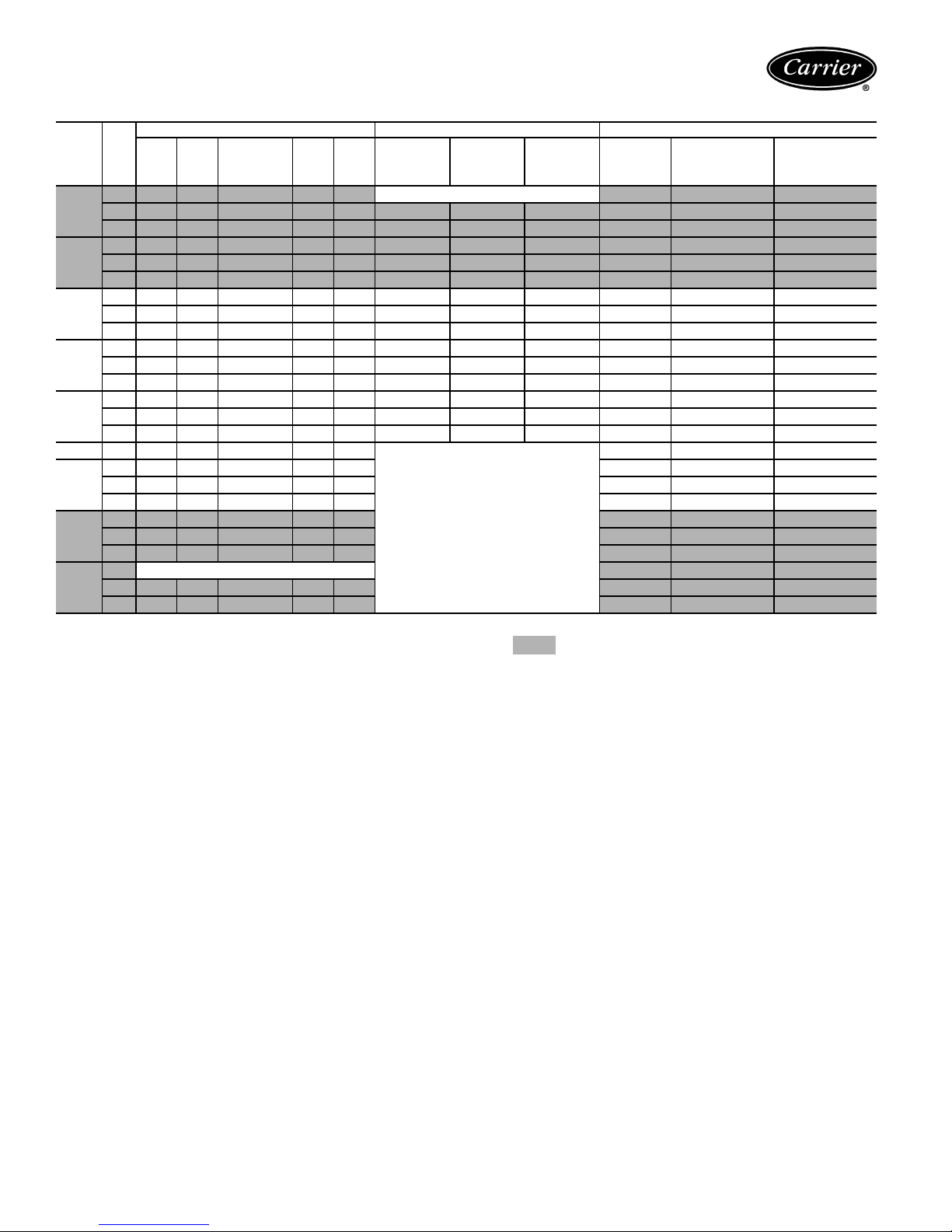
Page 16
Performance data
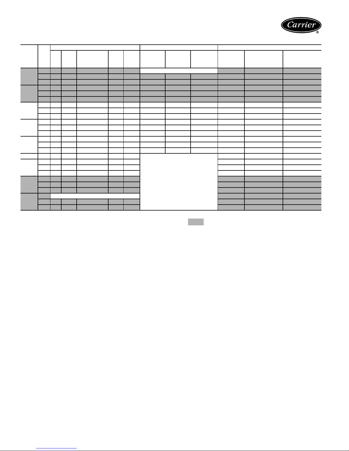
50KQA,KQD007 (1/2 TON) — RATED AIRFLOW 280 CFM
COOLING — EAT 80
EWT F GPM
1.5 8.7 6.3 0.72 0.42 10.2
1.9 8.8 6.3 0.72 0.42 10.2 6.6 0.59 4.6 2.3 3.0 3.6
40
2.5 8.9 6.3 0.71 0.42 10.3 6.7 0.58 4.8 5.0 6.2 7.3
1.5 8.4 6.2 0.74 0.44 9.9 7.4 0.61 5.4 1.8 2.2 2.6
1.9 8.5 6.3 0.74 0.44 10.0 7.6 0.60 5.5 2.3 3.0 3.6
50
2.5 8.6 6.3 0.73 0.43 10.0 7.7 0.60 5.7 5.0 6.2 7.3
1.5 8.1 6.1 0.75 0.47 9.7 8.4 0.62 6.3 1.8 2.2 2.6
1.9 8.2 6.1 0.75 0.46 9.8 8.6 0.61 6.5 2.3 3.0 3.6
60
2.5 8.2 6.1 0.75 0.46 9.8 8.8 0.63 6.6 5.0 6.2 7.3
1.5 7.8 6.0 0.77 0.51 9.5 9.4 0.64 7.2 1.8 2.2 2.6
1.9 7.8 6.0 0.76 0.50 9.6
70*
2.5 7.9 6.0 0.76 0.49 9.6 9.8 0.65 7.6 5.0 6.2 7.3
1.5 7.4 5.8 0.78 0.56 9.3 10.4 0.67 8.2 1.8 2.2 2.6
1.9 7.5 5.9 0.78 0.55 9.4 10.7 0.66 8.4 2.3 3.0 3.6
80
2.5 7.6 5.9 0.78 0.54 9.4 10.9 0.68 8.6 5.0 6.2 7.3
1.9
85*
1.5 7.0 5.7 0.81 0.62 9.2 1.8 2.2 2.6
1.9 7.1 5.8 0.81 0.61 9.2 2.3 3.0 3.6
90
2.5 7.2 5.7 0.80 0.60 9.3 5.0 6.2 7.3
1.5 6.7 5.6 0.84 0.69 9.0 1.8 2.2 2.6
1.9 6.7 5.6 0.83 0.68 9.1 2.3 3.0 3.6
100
2.5 6.8 5.6 0.83 0.67 9.1 5.0 6.2 7.3
1.5
1.9 6.3 5.4 0.86 0.76 8.9 2.3 3.0 3.6
110
2.5 6.4 5.5 0.85 0.74 8.9 5.0 6.2 7.3
TC TSC
7.3 5.8 0.79 0.58 9.3
Sensible/
Tot al Ra tio
Operation Not Recommended
LEGEND
DB —
EWT —
GPM —
MBtuh —
TC —
THA —
THR —
TSC —
WB —
WLHP —
*ARI 320 points (bold printing) are shown for comparison purposes
only. These are not certified data points.
Dry Bulb
Entering Water Temperature (F)
Gallons per Minute
Btuh in Thousands
Total Capacity
Total Heat of Absorption (MBtuh)
Total Heat of Rejection (MBtuh)
Total Sensible Cooling (MBtuh)
Wet Bulb
Water Loop Heat Pump
F DB/67
F WB HEATING — EAT 70
kW THR TC kW THA
Operation Not Recommended
9.6 0.64 7.4 2.3 3.0 3.6
Operation Not Recommended
F DB PRESSURE DROP (ft wg)
Without
Motorized
Val ve
1.8 2.2 2.6
2.3 3.0 3.6
1.8 2.2 2.6
With
Motorized
Cv = 3.5
MOPD = 20 psi
With
Motorized
Cv = 2.5
MOPD = 50 psi
NOTES:
1. Shaded boxed areas represent KQD units only.
2. MOPD = Maximum Operating Pressure Differential (water pressure differential at unit cannot exceed MOPD or water valve cannot
close).
3. Interpolation is permissible, extrapolation is not.
4. All entering air conditions are 80 F db and 67 F wb in cooling and
70 F db in heating.
5. All performance data is based upon the lower voltage of dual voltage rated units. See Performance Correction Tables on page 21
for operating conditions other than those listed above.
6. ARI/ASHRAE/ISO 13256-1 (WLHP application) certified conditions are 86 F EWT, 80.6 F db and 66.2 F wb in cooling and 68 F
EWT, 68 F db and 59 F wb in heating.
16
Page 17
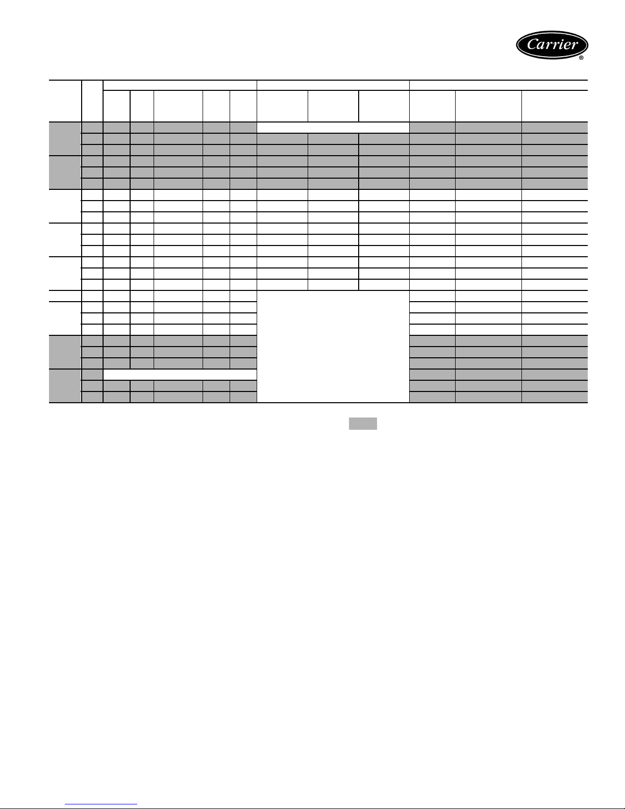
50KQA,KQD009 (3/4 TON) — RATED AIRFLOW 280 CFM
COOLING — EAT 80
EWT F GPM
TC TSC
Sensible/
Tota l R a t i o
1.7 10.8 7.8 0.72 0.47 12.4
2.3 10.9 7.8 0.72 0.45 12.4 8.1 0.66 5.9 4.3 5.3 6.3
40
3.0 10.9 7.8 0.72 0.44 12.4 8.2 0.67 6.0 7.2 8.9 10.5
1.7 10.4 7.6 0.73 0.51 12.2 9.0 0.70 6.7 2.3 2.8 3.4
2.3 10.5 7.6 0.73 0.49 12.2 9.3 0.70 6.9 4.3 5.3 6.3
50
3.0 10.5 7.7 0.73 0.48 12.2 9.4 0.71 7.0 7.2 8.9 10.5
1.7 10.0 7.4 0.74 0.56 11.9 10.2 0.73 7.7 2.3 2.8 3.4
2.3 10.1 7.5 0.74 0.55 12.0 10.4 0.73 7.9 4.3 5.3 6.3
60
3.0 10.2 7.5 0.74 0.54 12.0 10.6 0.74 8.1 7.2 8.9 10.5
1.7 9.7 7.3 0.75 0.63 11.8 11.3 0.77 8.7 2.3 2.8 3.4
2.3 9.8 7.3 0.75 0.61 11.9
70*
3.0 9.8 7.4 0.75 0.60 11.9 11.9 0.79 9.2 7.2 8.9 10.5
1.7 9.3 7.2 0.77 0.69 11.7 12.6 0.82 9.8 2.3 2.8 3.4
2.3 9.4 7.2 0.76 0.67 11.7 12.9 0.82 10.1 4.3 5.3 6.3
80
3.0 9.5 7.2 0.76 0.66 11.7 13.2 0.84 10.3 7.2 8.9 10.5
2.3
85*
9.2 7.1 0.77 0.72 11.7
1.7 9.0 7.0 0.78 0.77 11.6 2.3 2.8 3.4
2.3 9.0 7.0 0.78 0.74 11.6 4.3 5.3 6.3
90
3.0 9.1 7.0 0.77 0.73 11.6 7.2 8.9 10.5
1.7 8.6 6.8 0.79 0.84 11.5 2.3 2.8 3.4
2.3 8.7 6.9 0.79 0.83 11.5 4.3 5.3 6.3
100
3.0 8.7 6.9 0.79 0.81 11.5 7.2 8.9 10.5
1.7
2.3 8.3 6.7 0.81 0.91 11.4 4.3 5.3 6.3
110
Operation Not Recommended
3.0 8.3 6.7 0.80 0.89 11.4 7.2 8.9 10.5
LEGEND
DB —
EWT —
GPM —
MBtuh —
TC —
THA —
THR —
TSC —
WB —
WLHP —
Dry Bulb
Entering Water Temperature (F)
Gallons per Minute
Btuh in Thousands
Total Capacity
Total Heat of Absorption (MBtuh)
Total Heat of Rejection (MBtuh)
Total Sensible Cooling (MBtuh)
Wet Bulb
Water Loop Heat Pump
*ARI 320 points (bold printing) are shown for comparison purposes
only. These are not certified data points.
F DB/67
F WB HEATING — EAT 70
kW THR TC kW THA
Operation Not Recommended
11.7 0.78 9.0 4.3 5.3 6.3
Operation Not Recommended
F DB PRESSURE DROP (ft wg)
Without
Motorized
Val ve
With
Motorized
Cv = 3.5
MOPD = 20 psi
With
Motorized
Cv = 2.5
MOPD = 50 psi
2.3 2.8 3.4
4.3 5.3 6.3
2.3 2.8 3.4
NOTES:
1. Shaded boxed areas represent KQD units only.
2. MOPD = Maximum Operating Pressure Differential (water pressure differential at unit cannot exceed MOPD or water valve cannot
close).
3. Interpolation is permissible, extrapolation is not.
4. All entering air conditions are 80 F db and 67 F wb in cooling and
70 F db in heating.
5. All performance data is based upon the lower voltage of dual voltage rated units. See Performance Correction Tables on page 21
for operating conditions other than those listed above.
6. ARI/ASHRAE/ISO 13256-1 (WLHP application) certified conditions are 86 F EWT, 80.6 F db and 66.2 F wb in cooling and 68 F
EWT, 68 F db and 59 F wb in heating.
17
Page 18
Performance data (cont)
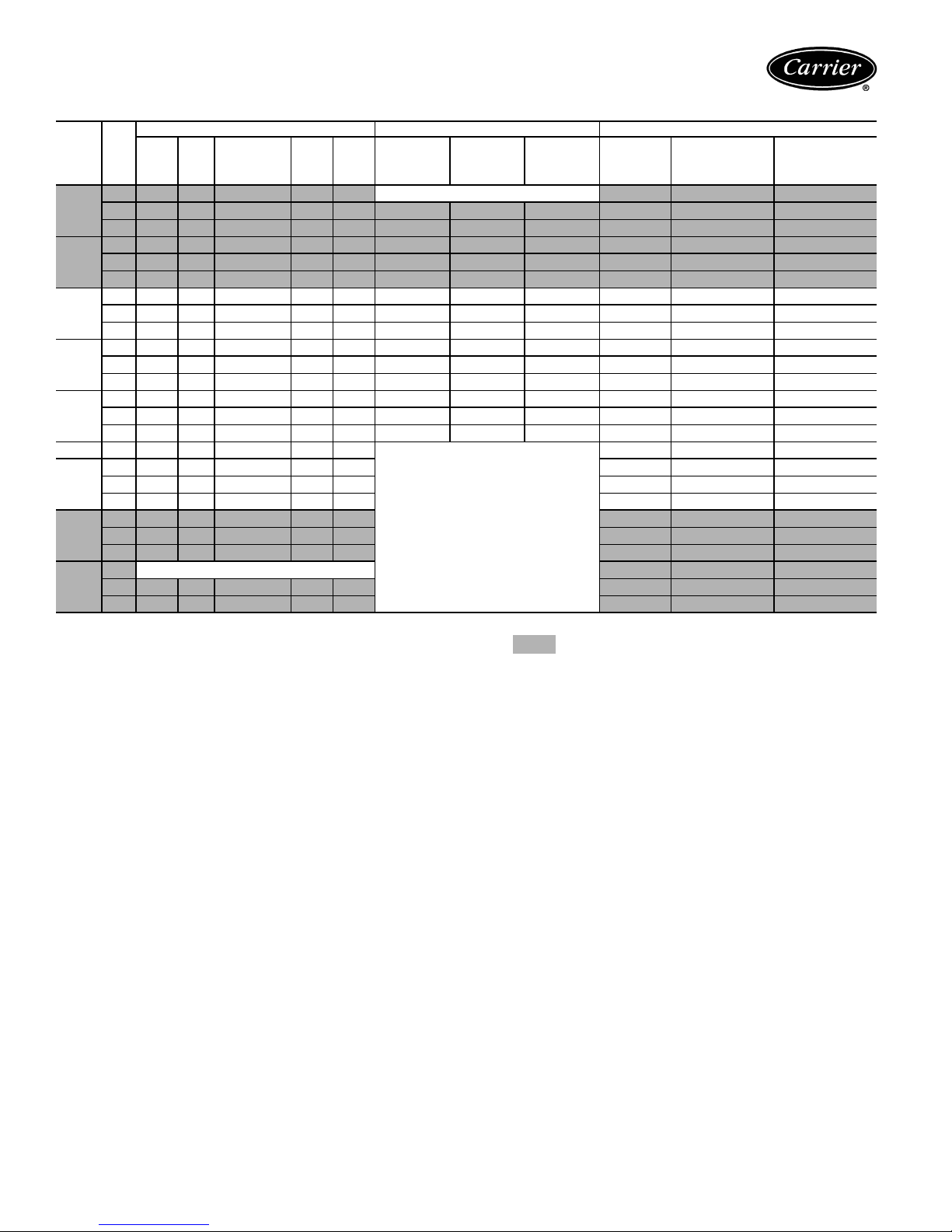
50KQA,KQD012 (1 TON) — RATED AIRFLOW 375 CFM
COOLING — EAT 80
EWT F GPM
TC TSC
Sensible/
Tota l R a t i o
2.3 13.8 7.3 0.53 0.67 16.1
3.0 13.9 7.4 0.53 0.64 16.1 9.5 0.85 6.6 9.7 11.4 13.0
40
4.0 14.0 7.4 0.53 0.63 16.2 9.7 0.86 6.8 16.6 19.6 22.5
2.3 13.3 7.4 0.55 0.74 15.9 10.7 0.89 7.6 5.5 6.5 7.5
3.0 13.5 7.4 0.55 0.72 15.9 10.9 0.89 7.9 9.7 11.4 13.0
50
4.0 13.6 7.5 0.55 0.70 16.0 11.1 0.90 8.0 16.6 19.6 22.5
2.3 12.9 7.4 0.58 0.82 15.7 12.1 0.93 8.9 5.5 6.5 7.5
3.0 13.0 7.5 0.57 0.79 15.7 12.3 0.95 9.1 9.7 11.4 13.0
60
4.0 13.1 7.5 0.57 0.78 15.8 12.5 0.97 9.2 16.6 19.6 22.5
2.3 12.4 7.4 0.60 0.89 15.5 13.5 0.99 10.1 5.5 6.5 7.5
3.0 12.5 7.5 0.60 0.87 15.5
70*
4.0 12.6 7.5 0.59 0.85 15.5 14.0 1.00 10.6 16.6 19.6 22.5
2.3 11.9 7.3 0.62 0.97 15.2 14.9 1.04 11.4 5.5 6.5 7.5
3.0 12.0 7.4 0.61 0.95 15.3 15.3 1.06 11.6 9.7 11.4 13.0
80
4.0 12.1 7.4 0.61 0.93 15.3 15.5 1.06 11.9 16.6 19.6 22.5
3.0
85*
11.8 7.3 0.62 0.99 15.2
2.3 11.4 7.2 0.63 1.05 15.0 5.5 6.5 7.5
3.0 11.5 7.3 0.63 1.03 15.0 9.7 11.4 13.0
90
4.0 11.6 7.2 0.62 1.01 15.1 16.6 19.6 22.5
2.3 10.9 6.6 0.61 1.14 14.8 5.5 6.5 7.5
3.0 11.0 6.7 0.60 1.12 14.8 9.7 11.4 13.0
100
4.0 11.1 6.7 0.60 1.10 14.8 16.6 19.6 22.5
2.3
3.0 10.5 6.0 0.57 1.20 14.6 9.7 11.4 13.0
110
Operation Not Recommended
4.0 10.6 6.0 0.57 1.19 14.6 16.6 19.6 22.5
LEGEND
DB —
EWT —
GPM —
MBtuh —
TC —
THA —
THR —
TSC —
WB —
WLHP —
Dry Bulb
Entering Water Temperature (F)
Gallons per Minute
Btuh in Thousands
Total Capacity
Total Heat of Absorption (MBtuh)
Total Heat of Rejection (MBtuh)
Total Sensible Cooling (MBtuh)
Wet Bulb
Water Loop Heat Pump
*ARI 320 points (bold printing) are shown for comparison purposes
only. These are not certified data points.
F DB/67
F WB HEATING — EAT 70
kW THR TC kW THA
Operation Not Recommended
13.8 1.01 10.3 9.7 11.4 13.0
Operation Not Recommended
F DB PRESSURE DROP (ft wg)
Without
Motorized
Val ve
With
Motorized
Cv = 3.5
MOPD = 20 psi
With
Motorized
Cv = 2.5
MOPD = 50 psi
5.5 6.5 7.5
9.7 11.4 13.0
5.5 6.5 7.5
NOTES:
1. Shaded boxed areas represent KQD units only.
2. MOPD = Maximum Operating Pressure Differential (water pressure differential at unit cannot exceed MOPD or water valve cannot
close).
3. Interpolation is permissible, extrapolation is not.
4. All entering air conditions are 80 F db and 67 F wb in cooling and
70 F db in heating.
5. All performance data is based upon the lower voltage of dual voltage rated units. See Performance Correction Tables on page 21
for operating conditions other than those listed above.
6. ARI/ASHRAE/ISO 13256-1 (WLHP application) certified conditions are 86 F EWT, 80.6 F db and 66.2 F wb in cooling and 68 F
EWT, 68 F db and 59 F wb in heating.
18
Page 19
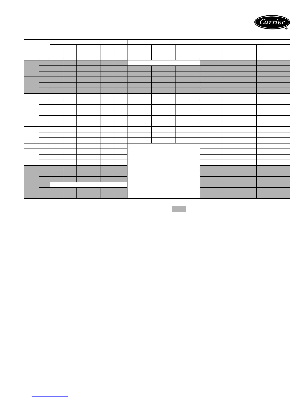
50KQA,KQD015 (11/4 TON) — RATED AIRFLOW 400 CFM
COOLING — EAT 80
EWT F GPM
TC TSC
Sensible/
Tota l Rat io
2.7 16.6 10.8 0.65 0.84 19.4
3.7 16.8 10.9 0.65 0.80 19.5 11.8 1.15 7.8 3.0 5.6 8.1
40
4.9 16.9 11.0 0.65 0.76 19.5 12.0 1.13 8.1 5.0 9.5 13.9
2.7 16.1 10.6 0.66 0.92 19.2 13.2 1.18 9.2 1.5 2.9 4.2
3.7 16.3 10.7 0.66 0.87 19.3 13.6 1.17 9.6 3.0 5.6 8.1
50
4.9 16.5 10.8 0.66 0.84 19.4 13.8 1.19 9.8 5.0 9.5 13.9
2.7 15.6 10.4 0.67 0.95 18.9 15.1 1.23 10.9 1.5 2.9 4.2
3.7 15.8 10.5 0.66 0.91 18.9 15.5 1.26 11.2 3.0 5.6 8.1
60
4.9 16.0 10.6 0.66 0.89 19.0 15.6 1.23 11.4 5.0 9.5 13.9
2.7 15.1 10.2 0.67 1.08 18.8 17.0 1.24 12.7 1.5 2.9 4.2
3.7 15.3 10.3 0.67 1.03 18.8
70*
4.9 15.5 10.3 0.67 1.01 18.9 17.8 1.31 13.4 5.0 9.5 13.9
2.7 14.5 10.0 0.69 1.18 18.6 18.7 1.34 14.2 1.5 2.9 4.2
3.7 14.8 10.0 0.68 1.14 18.7 19.3 1.34 14.7 3.0 5.6 8.1
80
4.9 14.9 10.1 0.68 1.11 18.7 19.6 1.37 15.0 5.0 9.5 13.9
3.7
85*
14.5 9.0 0.62 1.13 18.4
2.7 13.6 8.4 0.62 1.25 17.9 1.5 2.9 4.2
3.7 13.8 8.5 0.61 1.21 18.0 3.0 5.6 8.1
90
4.9 14.0 8.5 0.61 1.19 18.1 5.0 9.5 13.9
2.7 12.8 7.8 0.61 1.39 17.5 1.5 2.9 4.2
3.7 13.0 7.9 0.61 1.35 17.6 3.0 5.6 8.1
100
4.9 13.1 7.9 0.61 1.32 17.6 5.0 9.5 13.9
2.7
3.7 12.1 7.3 0.60 1.48 17.1 3.0 5.6 8.1
110
Operation Not Recommended
4.9 12.2 7.3 0.60 1.45 17.2 5.0 9.5 13.9
LEGEND
DB —
EWT —
GPM —
MBtuh —
TC —
THA —
THR —
TSC —
WB —
WLHP —
Dry Bulb
Entering Water Temperature (F)
Gallons per Minute
Btuh in Thousands
Total Capacity
Total Heat of Absorption (MBtuh)
Total Heat of Rejection (MBtuh)
Total Sensible Cooling (MBtuh)
Wet Bulb
Water Loop Heat Pump
*ARI 320 points (bold printing) are shown for comparison purposes
only. These are not certified data points.
F DB/67
F WB HEATING — EAT 70
kW THR TC kW THA
Operation Not Recommended
17.5 1.28 13.1 3.0 5.6 8.1
Operation Not Recommended
F DB PRESSURE DROP (ft wg)
Without
Motorized
Val ve
With
Motorized
Cv = 3.5
MOPD = 20 psi
With
Motorized
Cv = 2.5
MOPD = 50 psi
1.5 2.9 4.2
3.0 5.6 8.1
1.5 2.9 4.2
NOTES:
1. Shaded boxed areas represent KQD units only.
2. MOPD = Maximum Operating Pressure Differential (water pressure differential at unit cannot exceed MOPD or water valve cannot
close).
3. Interpolation is permissible, extrapolation is not.
4. All entering air conditions are 80 F db and 67 F wb in cooling and
70 F db in heating.
5. All performance data is based upon the lower voltage of dual voltage rated units. See Performance Correction Tables on page 21
for operating conditions other than those listed above.
6. ARI/ASHRAE/ISO 13256-1 (WLHP application) certified conditions are 86 F EWT, 80.6 F db and 66.2 F wb in cooling and 68 F
EWT, 68 F db and 59 F wb in heating.
19
Page 20
Performance data (cont)
50KQA,KQD019 (11/2 TON) — RATED AIRFLOW 430 CFM
COOLING — EAT 80
EWT F
GPM
TC TSC
Sensible/
Tota l Rat io
3.5 19.4 12.0 0.62 0.99 22.8
4.5 19.6 12.1 0.62 0.96 22.9 15.3 1.40 10.5 4.2 8.0 11.7
40
6.0 19.8 12.2 0.62 0.92 22.9 15.6 1.43 10.7 8.3 15.1 21.6
3.5 18.9 11.7 0.62 1.09 22.6 17.0 1.46 12.0 2.6 4.9 7.1
4.5 19.0 11.8 0.62 1.05 22.6 17.4 1.50 12.3 4.2 8.0 11.7
50
6.0 19.2 11.9 0.62 1.03 22.7 17.7 1.53 12.5 8.3 15.1 21.6
3.5 18.3 11.4 0.63 1.19 22.3 19.1 1.56 13.8 2.6 4.9 7.1
4.5 18.4 11.5 0.62 1.16 22.4 19.6 1.59 14.1 4.2 8.0 11.7
60
6.0 18.6 11.6 0.62 1.13 22.5 20.0 1.63 14.4 8.3 15.1 21.6
3.5 17.6 11.2 0.64 1.30 22.1 21.3 1.65 15.7 2.6 4.9 7.1
4.5 17.8 11.3 0.63 1.27 22.1
70*
6.0 17.9 11.3 0.63 1.25 22.2 22.1 1.70 16.3 8.3 15.1 21.6
3.5 17.4 10.9 0.63 1.45 22.3 23.6 1.77 17.6 2.6 4.9 7.1
4.5 17.6 11.0 0.63 1.42 22.4 24.2 1.77 18.2 4.2 8.0 11.7
80
6.0 17.7 11.1 0.63 1.39 22.5 24.7 1.81 18.6 8.3 15.1 21.6
4.5
85*
17.5 10.9 0.62 1.49 22.6
3.5 16.3 10.6 0.65 1.52 21.5 2.6 4.9 7.1
4.5 16.5 10.7 0.65 1.50 21.6 4.2 8.0 11.7
90
6.0 16.6 10.7 0.65 1.47 21.6 8.3 15.1 21.6
3.5 15.6 10.3 0.66 1.66 21.3 2.6 4.9 7.1
4.5 15.8 10.4 0.66 1.62 21.3 4.2 8.0 11.7
100
6.0 15.9 10.4 0.65 1.59 21.3 8.3 15.1 21.6
3.5
4.5 15.0 10.1 0.67 1.75 21.0 4.2 8.0 11.7
110
Operation Not Recommended
6.0 15.2 10.1 0.67 1.72 21.0 8.3 15.1 21.6
LEGEND
DB —
EWT —
GPM —
MBtuh —
TC —
THA —
THR —
TSC —
WB —
WLHP —
Dry Bulb
Entering Water Temperature (F)
Gallons per Minute
Btuh in Thousands
Total Capacity
Total Heat of Absorption (MBtuh)
Total Heat of Rejection (MBtuh)
Total Sensible Cooling (MBtuh)
Wet Bulb
Water Loop Heat Pump
*ARI 320 points (bold printing) are shown for comparison purposes
only. These are not certified data points.
F DB/67
F WB HEATING — EAT 70
kW THR TC kW THA
Operation Not Recommended
21.9 1.69 16.1 4.2 8.0 11.7
Operation Not Recommended
F DB PRESSURE DROP (ft wg)
Without
Motorized
Val ve
With
Motorized
Cv = 3.5
MOPD = 20 psi
With
Motorized
Cv = 2.5
MOPD = 50 psi
2.6 4.9 7.1
4.2 8.0 11.7
2.6 4.9 7.1
NOTES:
1. Shaded boxed areas represent KQD units only.
2. MOPD = Maximum Operating Pressure Differential (water pressure differential at unit cannot exceed MOPD or water valve cannot
close).
3. Interpolation is permissible, extrapolation is not.
4. All entering air conditions are 80 F db and 67 F wb in cooling and
70 F db in heating.
5. All performance data is based upon the lower voltage of dual voltage rated units. See Performance Correction Tables on page 21
for operating conditions other than those listed above.
6. ARI/ASHRAE/ISO 13256-1 (WLHP application) certified conditions are 86 F EWT, 80.6 F db and 66.2 F wb in cooling and 68 F
EWT, 68 F db and 59 F wb in heating.
20
Page 21
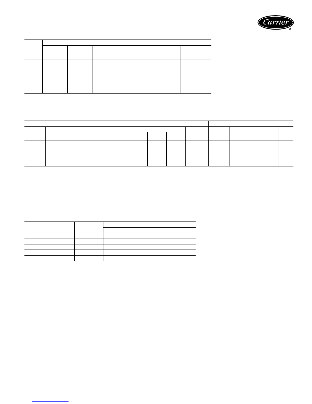
NOMINAL CFM CORRECTIONS
SCFM
(%)
67% 0.951 0.912 0.905 0.946 0.971 1.110 0.856
73% 0.961 0.930 0.924 0.957 0.977 1.088 0.885
80% 0.971 0.947 0.943 0.968 0.982 1.066 0.914
87% 0.980 0.964 0.961 0.978 0.988 1.045 0.941
92% 0.990 0.982 0.981 0.989 0.994 1.023 0.971
100% 1.000 1.000 1.000 1.000 1.000 1.000 1.000
107% 1.011 1.019 1.021 1.012 1.006 0.976 1.031
113% 1.020 1.035 1.038 1.022 1.012 0.956 1.058
Cooling
Capacity
COOLING CORRECTIONS HEATING CORRECTIONS
Tota l
Sensible
Cooling
Capacity
Power
Input
Wat ts
Heat of
Rejection
Heating
Capacity
Powe r
Watt s
Input
Heat of
Absorption
ENTERING AIR CORRECTIONS
COOLING CORRECTIONS HEATING CORRECTIONS
Entering
Air Wet
Bulb F
61
64 0.955 0.615 0.881 1.110 1.129 1.266 * 0.948 65 1.030 1.023 0.970
66.2 0.994 0.506 0.773 1.030 1.048 1.184 * 0.982 68 1.008 1.006 0.992
67 1.000
70 1.045 * 0.585 0.852 0.884 1.118 1.312 1.052 75 0.970 0.977 1.030
73 1.090 * 0.436 0.703 0.735 0.970 1.234 1.111 80 0.940 0.953 1.060
DB —
SCFM —
WB —
*Sensible capacity equals total capacity.
Tot al
Cooling
Capacity
0.910 0.763 1.030 1.242 * * * 0.893 60 1.060 1.047 0.940
LEGEND
Dry Bulb
Standard Cubic Feet per Minute
Wet Bulb
Sensible Cooling Capacity Entering Dry Bulb
70
F DB 75
0.466 0.733
F DB 80
F DB 80.6
1.000
F DB 85
1.018 1.154 1.390
Heat of
F DB 90
NOTES:
1.
2. ARI/ISO/ASHRAE 13256-1 uses entering air conditions of Cooling
3. Discontinued Standards ARI 320, 325, and 330 used entering air
Rejection
F DB
1.000 70 1.000 1.000 1.000
indicates performance data table conditions.
Bold
— 80.6 F DB/66.2 F WB and Heating — 68 F DB/59 F WB and
high fan speed.
conditions of Cooling — 80 F DB/67 F WB and Heating — 70 F DB
(bold print).
Entering
Air Dry
Bulb F
Heating
Capacity
Heat of
Absorption
Powe r
Input
Watts
50KQA,KQD CONSOLE BLOWER PERFORMANCE 60 Hz
50KQA,KQD
007
009
012
015
019
NOTES:
1. Fan speed is field adjustable.
2. All airflow is rated at lowest voltage if unit is dual voltage rated, i.e., 208 v for 208-230 v
units.
3. All units ARI/ISO/ASHRAE 13256-1 rated on high fan speed.
4. All units are designed and rated for zero external static pressure (non-ducted) application.
RATED
CFM
280 240 280
280 240 280
375 320 375
400 350 400
430 370 430
Low Speed High Speed
SCFM
21
Page 22
Application data
Aquazone™ water source heat pump products are available
in a flexible, efficient array of models, which can be used in
all types of water loop, ground water, and ground loop
type systems. Use Aquazone products to provide optimal
energy efficient solutions and adapt to the most challenging design requirements.
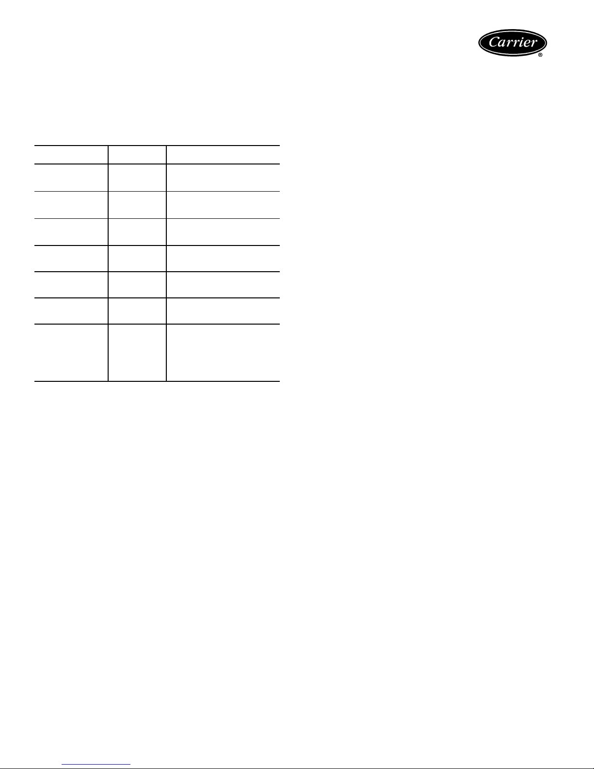
AQUAZONE PRODUCT GUIDE
50 SERIES
50RHC,RVC
Horizontal/Vertical
50RHR,RVR
Horizontal/Vertical
50RHS,RVS
Horizontal/Vertical
50HQ,VQ
Horizontal/Vertical
50KQ
50RTG
50RWS
TYPE
SIZE (tons)
Standard
Efficiency
1
/2-5
High
Efficiency
1
/2-5
Premium
Efficiency
1
/4-6
1
Large Capacity
1
6
/2-25
Console
1
/2-11/
2
Rooftop
3-20
Water-to-Water
3-30
APPLICATION
Efficient, compact, low cost
alternative for retrofit or new
boiler/tower systems.
Efficient, adaptable unit for
new boiler/tower, ground
water, or ground loop systems.
Premium, ultra efficient unit for
new boiler/tower, ground
water, or ground loop systems
Designed to handle large
zoned areas for all
applications.
Attractive design for finished
interior, under-window
installations.
Economical solution for IAQ
problems and tempering
ventilation air.
Used to pre-heat or cool
air and can be used as a
stand-alone or supplemental
boiler/chiller in most hydronic
heating applications. Also
conditions process fluids,
lubricants and refrigerants.
Water loop system
Water loop (or boiler/tower) system applications typically
include a number of units plumbed to a common piping
system. For optimal performance, design this system between 2.25 and 3 gpm per ton of cooling capacity. The
system is comprised of highly efficient packaged reverse
cycle heat pump units interconnected by a water loop. The
water circuit serves as both a sink and source for heat absorption and rejection and is designed for entering water
temperatures between 60 F and 90 F. Within this temperature range, units can heat or cool from the same water
source. Transferring heat from warm to cold spaces in the
building, whenever they coexist, conserves energy rather
than creating new heat.
Refer to the
tem Design Guide
systems. The guide includes a practical approach for the
latest and most current design recommendations including:
• Horizontal, vertical, console, rooftop and water-towater product applications.
• Ventilation methods and system design including energy
recovery.
• Acoustical considerations for different product types.
• Addressing IAQ issues such as condensate removal,
humidity control.
Carrier Water Source Heat Pump Sys-
for assistance designing water loop
• Air distribution design including diffuser selection/
layout and ductwork design.
• Hydronic system design including pipe sizing/layout
and boiler/tower sizing.
• Control configurations such as stand alone, DDC, DCV,
and VVT®.
• WSHP efficiency/operational cost comparison chart.
• System variations such as a system without a boiler,
variable pumping, and VAV for interior use.
Ground water systems
To use Aquazone units in ground water applications, you
should specify extended range. This will provide factoryinstalled coaxial coil insulation to prevent condensate from
dripping when entering water temperatures are below
60 F. In addition, the copper coaxial coil installed on the
Aquazone units may not be suitable for all water conditions. Refer to the Water Conditioning section for proper
coaxial coil material selection.
Surface water system —
This system is typically located
near a lake or pond. In this application, the loop can be
submerged in a series of coils beneath the water surface.
The number of coils required depends on system load and
design. This application requires minimum piping and
excavation.
Open loop system —
Use this system where ground
water is plentiful. In this application, ground water is
pumped through supply piping from the well to the building. The water is then pumped back into the ground
through a discharge well as it leaves the building. An additional heat exchanger is usually installed between the building water piping system and the ground water piping system. This design limits piping and excavation.
Aquazone units include a standard TXV and are rated to
extremely low temperatures to self-adjust the refrigeration
circuit. Therefore, open loop systems do not require water
regulating valves. We recommend a slow opening/closing
solenoid valve to conserve water.
Ground loop systems
There are many commonly specified designs for ground
loop applications. Typical designs include vertical loops
and horizontal loops. In some applications, water is piped
from the ground or lake directly to the water source heat
pump. This system only requires piping to get the water
from the source to the unit.
NOTE: When utilizing Aquazone water source heat pumps
in ground loop systems, refer to the design considerations
in the ground water system section.
Horizontal ground loop —
quate space is available and trenching can be easily accomplished. A series of parallel pipes are laid out in trenches 3
to 6 feet below the ground surface, and then back-filled.
Often, multiple pipes are used to maximize each trench’s
heat transfer capability. Ground conditions, heating and
cooling requirements, and system design determine piping
requirements and ground loop field size.
Use this system when ade-
22
Page 23
Vertical ground loop —
Use this system in vertical borehole applications. This design is well suited for retrofit applications when space is limited or where landscaping is already complete and minimum site disruption is desired.
The vertical ground loop system contains a single loop of
pipe inserted into a hole. The hole is back-filled and grouted after the pipe is inserted. The completed loop is concealed below ground. The number of loops required depends on ground conditions, heating and cooling requirements, and the depth of each hole.
Hybrid systems —
In some applications, it may be beneficial to incorporate a cooling tower into the ground loop
system to reduce the overall cost. A Hybrid System discards excess heat into the air and increases the cooling
performance of the ground loop.
Condensate drainage
Connect the console unit condensate drain to the building
condensate drain with a flexible, non-pressure rate plastic
hose. Be sure to avoid kinks in this hose to ensure an unobstructed flow of condensate from the unit to the drain.
The condensate hose’s horizontal run is usually too short
to pose any drainage problems, however, make sure this
line is pitched at least 1 inch for every 10 feet of run (in the
direction of the flow.) Avoid low points and unpitched
piping since dirt collects in these areas and may cause stoppage and overflow.
Installing a trap or drain in the field is not required unless
specified by local codes. The 50KQA, KQD units are
designated in a blow-thru configuration. The condensate
drain pan is located on the outlet side of the blower so that
the pressure in the drain pan is higher than the atmospheric pressure.
Water conditioning
In some applications, maintaining proper water quality
may require higher corrosion protection for the water-torefrigerant heat exchanger. Water quality varies from location to location and is unique for each job. Water characteristics such as pH value, alkalinity, hardness, and specific
conductance are important when considering any WSHP
application. Water typically includes impurities and hardness that must be removed. The required treatment depends on the water quality as well as system type. Water
problems fall into three main categories:
1. Scale formation caused by hard water reduces the
heat transfer rate and increases the water pressure
drop through the heat exchanger. As water is heated,
minerals and salts are precipitated from a solution
and deposited on the inside surface of the pipe or
tube.
2. Corrosion is caused by absorption of gases from the
air coupled with water on exposed metal. Corrosion
is also common in salt-water areas.
3. Organic growths, such as algae, can reduce the heat
transfer rate by forming an insulating coating on the
inside tube surface. Algae can also promote corrosion
by pitting.
NOTE: In most commercial water loop applications, Aquazone™ WSHP units use copper water-to-refrigerant heat
exchanger. Units can also be equipped with a Cupronickel
heat exchanger for applications where water is outside the
copper heat exchanger’s standard contaminant limits.
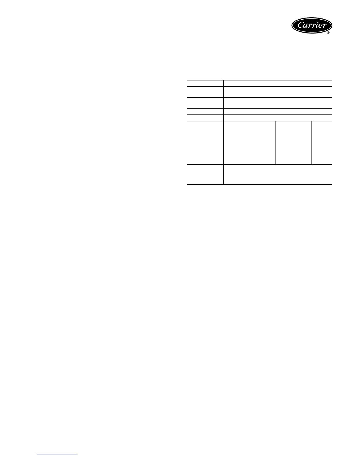
WATER QUALITY GUIDELINES
CONDITION ACCEPTABLE LEVEL
pH
Total Hardness
Iron Oxides
Iron Bacteria
Corrosion*
Brackish
*If the concentration of these corrosives exceeds the maximum allow-
able level, then the potential for serious corrosion problems exists.
†Sulfides in the water quickly oxidize when exposed to air, requiring that
no agitation occur as the sample is taken. Unless tested immediately
at the site, the sample will require stabilization with a few drops of one
Molar zinc acetate solution, allowing accurate sulfide determination up
to 24 hours after sampling. A low pH and high alkalinity cause system
problems, even when both values are within ranges shown. The term
pH refers to the acidity, basicity, or neutrality of the water supply. Below
7.0, the water is considered to be acidic. Above 7.0, water is considered to be basic. Neutral water contains a pH of 7.0.
NOTE: To convert ppm to grains per gallon, divide by 17. Hardness in
mg/l is equivalent to ppm.
7 to 9 range for copper. Cupronickel may be
used in the 5 to 9 range.
Calcium and magnesium carbonate should not
exceed 20 grains per gallon (350 ppm).
Less than 1 ppm.
No level allowable.
Max Allowable
Ammonia,
Ammonium Hydroxide
Ammonium Chloride,
Ammonium Nitrate
Ammonium Sulfate 0.5 ppm Cu
Chlorine/Chlorides 0.5 ppm CuNi
Hydrogen Sulfide† None Allowable —
Use Cupronickel heat exchanger when
concentrations of calcium or sodium chloride
are greater than 125 ppm are present.
(Seawater is approximately 25,000 ppm.)
Level
0.5 ppm Cu
0.5 ppm Cu
Coaxial
Metal
Acoustical design
Sound power levels represent the sound that the source,
the WSHP unit, produces with no regard to attenuation between the source and the space. Acoustical design goals
are necessary to provide criteria for occupied spaces.
These goals help ensure that people can be comfortable
and communicate effectively over the background noise of
the air-conditioning system and other background noise
sources.
Acoustical design goals are desirable sound pressure levels within a given conditioned space and are represented
by Noise Criteria (NC) curves. Noise Criteria (NC) curve
levels represent a peak over a full frequency spectrum. A
high value in a low frequency band has the same effect on
NC level as a lower value in a high frequency band. It is important that sound levels be balanced over the entire spectrum relative to the NC curve. The lower the NC criteria
curve, the more stringent the room acoustical design must
be to meet the design goals.
It is important to know how to convert the unit ratings
from sound power (Lw) to sound pressure (Lp). This conversion depends on the specifics of the installation’s acoustical environment. Assessing an area’s acoustical design requires that you compare the sound pressure (Lp) with the
NC curve for the selected area.
23
Page 24
Application data (cont)
Some of the factors that affect conversion of sound
power to sound pressure and consequent NC level include:
• Acoustical ceiling type
• Use of metal or flex duct
• Absorption in the occupied space
• Location in the occupied space
• Open or closed layout plan
• Use of open or ducted returns
• Orientation of unit to occupant
• Use of lined or unlined duct
OCTAVE BAND SOUND PRESSURE LEVEL (Lp)
NOISE
CRITERIA
CURVES
NC-15
NC-20
NC-25
NC-30
NC-35
NC-40
NC-45
NC-50
NC-55
NC-60
NC-65
ASSOCIATED WITH NC CURVES
OCTAVE BAND SOUND PRESSURE LEVEL (Lp)
Frequency (Hz)
63 125 250 500 1000 2000 4000 8000
49 36 26 17 17 14 12 11
52 41 33 27 22 19 17 16
54 45 38 31 27 24 22 21
58 49 41 36 31 29 28 27
61 53 45 40 36 34 33 32
64 57 50 45 41 39 38 37
67 61 54 49 46 44 43 42
71 64 58 54 51 49 48 47
74 68 63 58 56 54 53 52
77 71 67 63 61 59 58 57
80 75 71 68 66 64 63 62
WSHP sound control
Analyzing the projected sound level in the conditioned
space caused by a WSHP unit is quite involved. The key is
to have good sound power ratings (Lw) in dB on the equipment to determine the ductwork, ceiling and room sound
attenuation effect. We provide suggestions for console unit
sound design around the WSHP units.
Console units
With console units, the fan and compressor are located
within the space, and only the casing design attenuates the
transmission of sound sources into the space. The designer
should carefully review the manufacturer’s acoustical data
when selecting console units and use lower fan speeds to
minimize space noise.
Operating limits
Environment
This equipment is designed for indoor installation ONLY.
Power supply
A voltage variation of ± 10% of nameplate utilization voltage is acceptable.
Starting conditions
50KQA units
The 50KQA units start and operate in an ambient temperature of 40 F, with entering air temperature at 40 F, with
entering water temperature at 70 F, with both air and
water at the flow rate used in the ARI Standard 320-86
rating test, for initial start-up in winter.
50KQD units
The 50KQD unit will start and operate in an ambient temperature of 40 F, with entering air temperature at 40 F,
with entering water temperature at 40 F, with both air and
water at the flow rates used in the ARI Standard 320-86
rating test, for initial start-up in winter.
NOTE: These are not normal or continuous operating
conditions. We assume that such a start-up is used to bring
the building space up to occupancy temperature.
AIR LIMITS
50KQA 50KQD
Cooling Heating Cooling Heating
Min. Ambient Air
Rated Ambient Air
Max. Ambient Air
Min. Entering Air
Rated Entering Air, db/wb
Max. Entering Air, db/wb
50 F 50 F 40 F 40 F
80 F 70 F 80 F 70 F
100 F 85 F 100 F 85 F
50 F 50 F 50 F 40 F
80/67 F 70 F 80/67 F 70 F
100/83 F 80 F 100/83 F 80 F
WATER LIMITS
50KQA 50KQD
Cooling Heating Cooling Heating
Min. Entering Water
Normal Entering Water
Max. Entering Water
LEGEND
Dry Bulb
db —
Wet B ulb
wb —
NOTES:
1. Minimum Air and Water conditions can only be used at ARI flow
rates.
2. Only one maximum or minimum value may be used with 50KQA
units, all other parameters must be at normal conditions. The
50KQA units may have up two values at maximum or minimum
with all other parameters at normal conditions.
60 F 60 F 40 F 40 F
85 F 70 F 85 F 70 F
95 F 90 F 110 F 90 F
Solenoid valves
In applications using variable flow pumping, solenoid
valves can be factory installed and operated from the control board in the Aquazone™ WSHP unit.
Freeze protection
Applications where systems are exposed to outdoor
temperatures below freezing (32 F) must be protected from
freezing. The most common method of protecting water
systems from freezing is adding glycol concentrations into
the water. Use design care when selecting both the type
and concentrations of glycol due to the following:
• Equipment and performance may suffer with high concentrations of glycol and other antifreeze solutions
• Loss of piping pressure may increase greatly, resulting
in higher pumping costs
• Higher mixture viscosity may cause excess corrosion
and wear on the entire system
• The water’s acidity may be greatly increased, promoting
corrosion
Glycol promotes galvanic corrosion in systems of dissimilar
metals. The result is corrosion of one metal by the other,
causing leaks.
24
Page 25
Electrical data
50KQA,KQD
50KQA,KQD
FLA —
HACR —
LRA —
RLA —
RATED
VOLTAGE
115-1-60 104/126 6.2 36.2 0.50 6.9 8.5 15
007
009
012
015
019
Full Load Amps
Heating, Air Conditioning and Refrigeration
Locked Rotor Amps
Rated Load Amps
208/230-1-60 197/254 3.0 17.7 0.33 3.4 4.2 15
265-1-60 239/292 2.7 14.8 0.35 3.3 4.0 15
115-1-60 104/126 7.4 44.0 0.50 8.8 10.9 15
208/230-1-60 197/254 3.8 20.0 0.33 4.8 6.0 15
265-1-60 239/292 3.3 18.6 0.35 3.7 4.5 15
115-1-60 104/126 9.7 54.0 1.28 11.5 14.0 20
208/230-1-60 197/254 4.8 26.3 0.52 5.4 6.6 15
265-1-60 239/292 4.2 28.0 0.43 4.8 5.9 15
208/230-1-60 197/254 6.4 38.0 0.52 7.5 9.3 15
265-1-60 239/292 5.4 32.0 0.43 5.9 7.3 15
208/230-1-60 197/254 7.6 45.0 1.10 9.4 11.5 15
265-1-60 239/292 6.3 32.0 0.83 7.2 8.8 15
LEGEND
VOLTAGE
MIN/MAX
COMPRESSOR FAN
RLA LRA
MOTOR
FLA
TOTAL
UNIT
FLA
MIN
CIRCUIT
AMP
MAX
FUSE/
HACR
25
Page 26
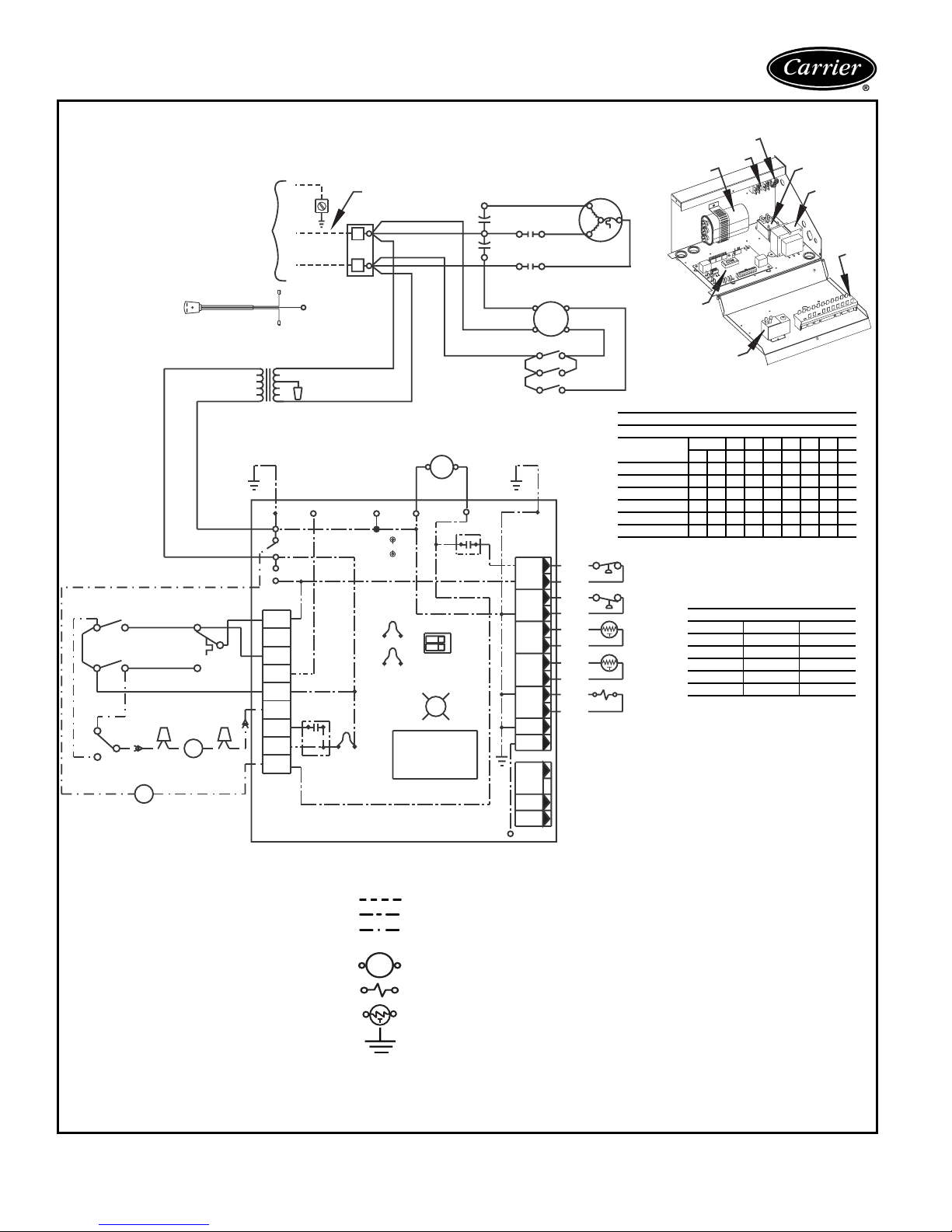
Typical wiring schematics
MANUAL CHANGEOVER WITH COMPLETE C CONTROLLER
Trans
C
R
AL1
AL2
Y
W
O
G
R
C
A
P1
>>>>>
>
L2
L1
L2 (ribbed)
L1 (plain)
Y
LEGEND
Ground
Ground
ORG
230V
Alarm
Relay
BLK
BR
Neutral on 265V Systems
2
PB
1
BRG
Test Pins
SEE
NOTE 4
JW3
FP1 Low Temp
JW2
FP2 Low Temp
JW1
SEE NOTE 6
----------
>
>
RED
CCG
Microprocessor
Control Logic
Use copper conductors only.
Refer to Disconnect
power supply connection
2A2
RED
PBS
3
3A
RED
GRY
1A
1
PBS
YEL
1B
BRN
AL —
BM —
BR —
Cap —
CO —
CR —
DM —
FP1 —
FP2 —
HP —
JW1 —
LOC —
PB —
PBS —
RVS —
Tra ns
—
UMT
—
UPM
—
WV
—
Power Supply
Refer to Data Plate
See Note 2
box for optional
Optional
Cord
Connection
24V
SEE
BLU
YEL
BRN
YEL
YEL
UMT
DM
1
2
ORG
3
RED
BRN
BRN
ORG
YEL
YEL
YEL
YEL
WV
Alarm Relay Contacts
Blower Motor
Blower Relay
Capacitor
Condensate Overflow
Compressor Relay
Damper Motor
Sensor, Water Coil Freeze Protection
Sensor, Air Coil Freeze Protection
High-Pressure Switch
Jumper Wire for Alarm
Loss of Charge Pressure Switch
Power Terminal Block
Push Button Switch
Reversing Valve Solenoid
Transformer
Unit Mounted Thermostat
Unit Performance Monitor
Water Valve
H
CAP
6
C
RED
BLK
CO
BRN
YEL
BLK
BLK
BLK
SEE
NOTE 7NOTE 7
HP
LOC
FP1
FP2
RV
CO
P2
24V
DC
EH1
EH2
CR
P3
BRN
(265V)
RED
(208V)
WHT
(115V)
10
CR
BRN
Compressor
Relay
Dip Switch
Off On
G
C
SEE
NOTE 3
CC
UPM
1
2
Not Used
Status
LED
F
YEL
Field Line Voltage Wiring
Field Low-Voltage Wiring
Printed Circuit Trace
Optional Low Voltage
Wiring
Relay Contactor Coil
Solenoid Coil
Thermistor
Ground
Mate-N-Lock
BLU
8
RED
42
BLK
BM
1
5A5
6A6
77A
PBS
1
2
3
4
5
6
7
8
9
10
12
Ground
PB
Cap
Compressor
S
R
C
B (HIGH)2
A (LOW)
RED
BLK
RED
RED
BLU
BRN
GRY
GRY
VIO
VIO
BRN
ORG
Not UsedNot Used
RED
Complete
C
UMT
PUSH BUTTON SWITCH ATTRIBUTES
X = CLOSED O = OPEN
TERMINALS
STOP
FAN ONLY
LOW COOL
HIGH COOL
LOW HEAT
HIGH HEAT
HP
LOC
FP1
SEE
NOTE 4
FP2
RVS
1 2345678
1A 1B 2A 3A 4A 5A 6A 7A 8A
XOOOOOOOO
XOOOOX OOO
OX XOOO XOO
OX XOOOO XO
XOOXXOXOO
XOOXXOOXX
BLOWER MOTOR WIRING
UNIT SIZE POLE A POL E B
007 5 3
009 5 3
012 5 4
015 4 3
019 4 3
NOTES:
1. Compressor and Blower Motor thermally protected internally.
2. All wiring to the unit must comply with NEC and
local codes.
3. Transformer is wired to 115V (WHT) lead for
115/1/60 units, 265V (BRN) Lead for 265/1/60
units or 208V (RED) Lead for 208/1/60. For
230/1/60 switch RED and ORG Leads at L1
and insulate RED lead. Transformer is energy
limiting or may have circuit breaker.
4. FP1 Thermistor provides freeze protection for
WATER. When using ANTI-FREEZE solutions,
cut JW3 jumper.
5. Typical unit-mounted thermostat wiring shown.
6. 24 V Alarm Signal shown. For Dry Alarm Contact, cut JW1 Jumper and Dry Contact will be
available between AL1 and AL2.
7. Transformer secondary ground via Complete C
board standoffs and screws to Control Box.
(Ground available from top two standoffs as
shown.)
CR
Transformer
PBS
26
Page 27
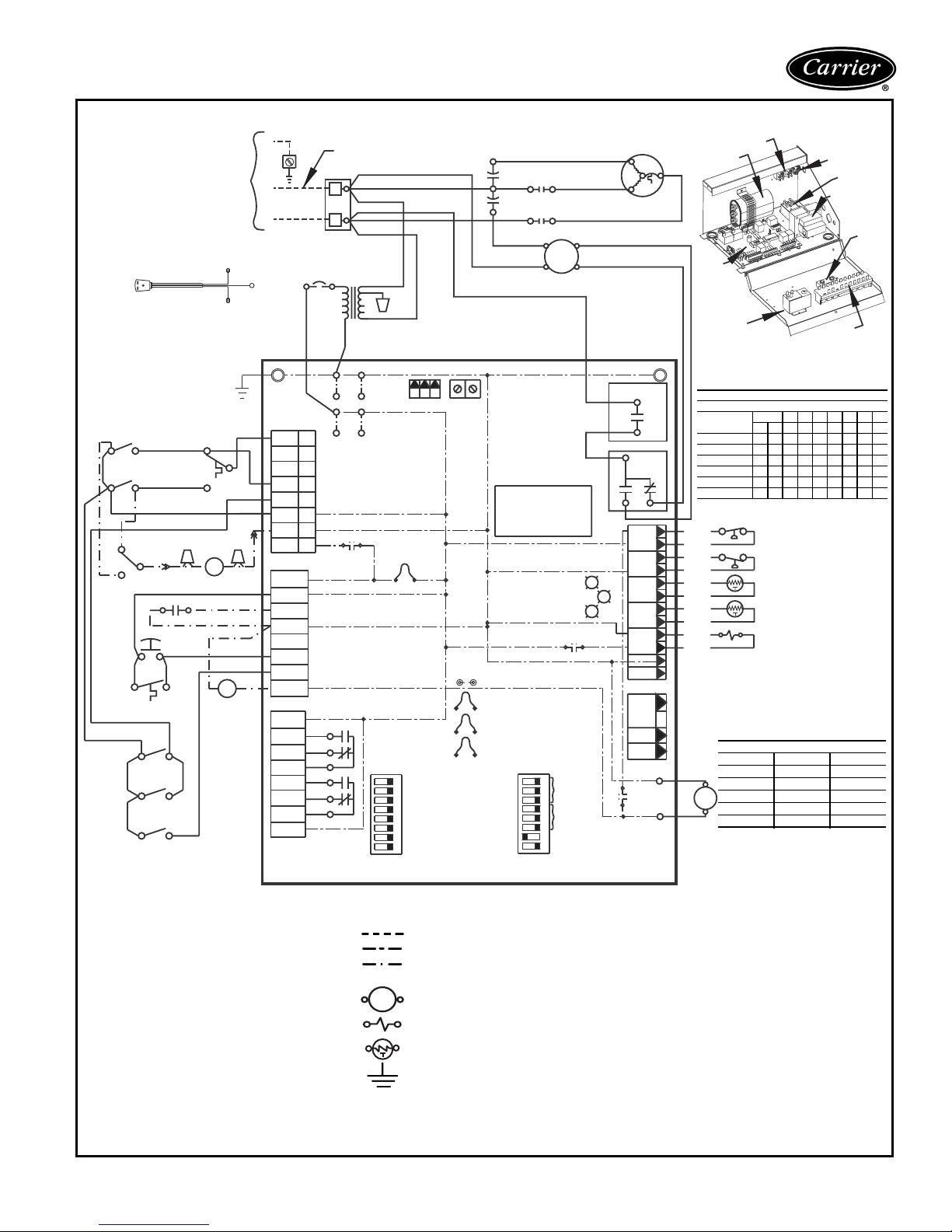
Power Supply
Refer to Data Plate
conductors only.
Refer to Disconnect
power supply connection
RED
2A
2
PBS
RED
3A
3
GRY
RED
1A
PBS
1B
RED
GRY
RED
RED
RED
AL —
BM —
Cap —
CB —
CO —
CR —
DM —
FP1 —
FP2 —
HP —
LOC —
NLL —
OS —
PB —
PBS —
RVS —
Tran s
—
UMT
—
UPM
—
WV
—
MANUAL CHANGEOVER WITH DELUXE D CONTROLLER
Ground
Use copper
See Note 2
box for optional
Optional
Cord
Connection
1
GRY
6A
7A
GRY
ORG
UMT
3
DM
YEL
TIME CLOCK
ORG
YEL
1
YEL
YEL
CLOSED=UNOCCUPIED
OS
WHT
NLL
5A5
PBS
6
7
Alarm Relay Contacts
Blower Motor
Capacitor
Circuit Breaker
Condensate Overflow
Compressor Relay
Damper Motor
Sensor, Water Coil Freeze Protection
Sensor, Air Coil Freeze Protection
High-Pressure Switch
Loss of Charge Pressure Switch
Night Low Limit Thermostat
Override Switch
Power Terminal Block
Push Button Switch
Reversing Valve Solenoid
Transformer
Unit Mounted Thermostat
Unit Performance Monitor
Water Valve
L2 (ribbed)
L1 (plain)
NOTE 7
2
ORG
BRN
WV
SEE
BRN
WHT
GRY
YEL
BRN
RED
YEL
L2
L1
Ground
P1
Y1
Y2
W1
O/W2
G
R
C
AL1
P2
AL2
R
NSB
C
ESD
OVR
H
A
P3
R
NO1
NC1
COM
NO2
NC2
COM
R
CB
YEL
1
2
3
4
5
6
7
8
ACC1
RELAY
ACC2
RELAY
LEGEND
Neutral on 265V Systems
2
PB
1
BLK
Trans
ORG
230V
BLU
C
R
ALARM
RELAY
NOTE 6
AL2 DRY
OFF ON
S1
DIP SWITCH
PACKAGE
----------
>
>
H
COM1
TEST
PINS
C
F
S
C
JW3
FP1
JW2
FP2
JW1
LP
RED
BRN
(265V)
RED
(208V)
WHT
(115V)
SEE
NOTE 3
S
R
C
COM2
SEE
JW4
1
UPM: Disable/Enable
2
Unit Stage: 2/1
T'stat: Heat Cool/Heat Pump
3
RV on B/RV on O
4
Dehumid/Normal
5
Not Used
6
Boilerless: Enable/Disable
7
Boilerless: 40°F/50°F
8
Field Line Voltage Wiring
Field Low-Voltage Wiring
Printed Circuit Trace
Optional Low Voltage
Wiring
Relay Contactor Coil
Solenoid Coil
Thermistor
Ground
Mate-N-Lock
CAP
6
RED
CR
2
BLK
BRN
YEL
GRY
Microprocessor
Control Logic
SEE
Low
NOTE 4
Low
N.O.
ON
OFF
S2
DIP SWITCH
PACKAGE
BLU
8
RED
4
BLK
B (HIGH)
2
BM
A (LOW)
1
FAN ENABLE
GRY
COM
D
STATUS
FAULT
RELAY
1
ACC1
2
Functions
3
4
ACC2
5
Functions
6
H: hi fan/dehumid
7
Not Used
8
NOTES:
NO
G
Y
TEST
R
RV
1. Compressor and Blower Motor thermally protected
COM
NO
S
R
RELAY
SPEED
RELAY
HP
LOC
FP1
FP2
RV
CO
24V
DC
EH1
EH2
COMPR
RELAY
FAN
P7
P6
10
12
1
2
3
4
5
6
7
8
9
CCG
Compressor
C
BLK
RED
NC
CC
RED
RED
BLU
BRN
GRY
GRY
VIO
VIO
BRN
ORG
Not Used
BRN
YEL
Deluxe
TERMINALS
FAN ONLY
LOW COOL
HIGH COOL
LOW HEAT
HIGH HEAT
CR
PB
Cap
D
UMT
PUSH BUTTON SWITCH ATTRIBUTES
X = CLOSE D O = OPEN
1 2345678
1A 1B 2A 3A 4A 5A 6A 7A 8A
XOOOOOOOO
STOP
XOOOOX OOO
OX XOOOX OO
OX XOOOOX O
XOOXXOXOO
XOOXXOOXX
HP
LOC
SEE
FP1
NOTE 4
FP2
RVS
BLOWER MOTOR WIRING
UNIT SIZE POLE A POLE B
007 5 3
1
009 5 3
012 5 4
015 4 3
0
019 4 3
internally.
2. All wiring to the unit must comply with NEC and local
codes.
3. Transformer is wired to 115V (WHT) lead for 115/1/60
units, 265V (BRN) Lead for 265/1/60 units or 208V
(RED) Lead for 208/1/60. For 230/1/60 switch RED
and ORG Leads at L1 and insulate RED lead. Transformer is energy limiting or may have circuit breaker.
4. FP1 Thermistor provides freeze protection for
WATER. When using ANTI-FREEZE solutions, cut
JW3 jumper.
5. Typical unit-mounted thermostat wiring shown.
6. 24 V Alarm Signal shown. For Dry Alarm Contact, cut
AL2DRY (JW4) Jumper and Dry Contact will be available between AL1 and AL2.
7. Transformer secondary ground via Deluxe D board
standoffs and screws to Control Box. (Ground available from top two standoffs as shown.)
Ground
CR
Transformer
OS
PBS
27
Page 28
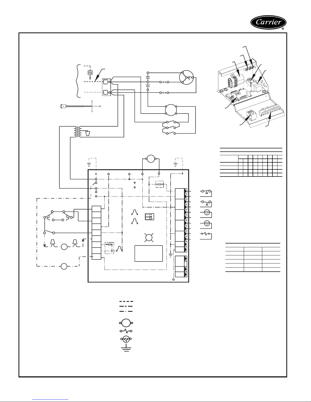
Typical wiring schematics (cont)
AUTOMATIC CHANGEOVER WITH COMPLETE C CONTROLLER
L2
L1
Ground
Neutral on 265V Systems
2
PB
1
RED
H
CAP
6
C
RED
BLK
CR
F
Power Supply
Refer to Data Plate
Use copper conductors only.
See Note 2
Refer to Disconnect
box for optional
power supply connection
Ground
PB
Compressor
Cap
BLU
S
R
8
RED
42
BLK
C
CR
Transformer
AL —
BM —
BR —
Cap —
CO —
CR —
DM —
FP1 —
FP2 —
HP —
JW1 —
LOC —
PB —
PBS —
RVS —
Tr an s
UMT
UPM
WV
Optional
Cord
Connection
Trans
24V
SEE
BLU
YEL
BRN
ORG
YEL
ORG
2
RED
BRN
BRN
YEL
UMT
4
1
ORG
5
YEL
RED
PBS
3A
YEL
YEL
BRN
Alarm Relay Contacts
Blower Motor
36
3
DM
YEL
WV
Blower Relay
Capacitor
Condensate Overflow
Compressor Relay
Damper Motor
Sensor, Water Coil Freeze Protection
Sensor, Air Coil Freeze Protection
High-Pressure Switch
Jumper Wire for Alarm
Loss of Charge Pressure Switch
Power Terminal Block
Push Button Switch
Reversing Valve Solenoid
Transformer
—
Unit Mounted Thermostat
—
Unit Performance Monitor
—
Water Valve
—
L2 (ribbed)
L1 (plain)
ORG
230V
C
R
Y
Y
W
O
G
R
C
AL1
AL2
A
P1
LEGEND
Ground
BLK
Alarm
Relay
BR
SEE NOTE 6
BRG
Test Pins
JW1
----------
BRN
(265V)
RED
SEE
(208V)
NOTE 3
WHT
(115V)
CCG
SEE
NOTE 4
JW3
FP1 Low Temp
JW2
FP2 Low Temp
Microprocessor
Control Logic
>
>
BRN
YEL
BLK
BLK
BLK
10
CR
BRN
CC
Compressor
Relay
Dip Switch
UPM
1
2
Not Used
Off On
Status
G
LED
C
YEL
B (HIGH)2
BM
1 A (LOW)
5A5
RED
6A6
77A
PBS
SEE
NOTE 7NOTE 7
1
HP
2
3
LOC
4
5
FP1
6
7
FP2
8
9
RV
10
12
CO
P2
24V
DC
EH1
EH2
P3
CO
Field Line Voltage Wiring
Field Low-Voltage Wiring
Printed Circuit Trace
Optional Low Voltage
Wiring
Relay Contactor Coil
Solenoid Coil
Thermistor
Ground
Mate-N-Lock
Complete
C
RED
BLK
RED
RED
BLU
BRN
GRY
GRY
VIO
VIO
BRN
ORG
Not UsedNot Used
HP
LOC
FP1
SEE
NOTE 4
FP2
RVS
UMT
PUSH BUTTON SWITCH ATTRIBUTES
X = CLOSED O = OPEN
TERMINALS
FAN ONLY
LOW FAN
HIGH FAN
1A 1B 2A 3A 4A 5A 6A 7A 8A
XOOOOOOOO
STOP
XOOOOX OOO
XOOXXOXOO
XOOXXOOX X
BLOWER MOTOR WIRING
UNIT SIZE POLE A POLE B
007 5 3
009 5 3
012 5 4
015 4 3
019 4 3
PBS
1 2345678
NOTES:
1. Compressor and Blower Motor thermally protected internally.
2. All wiring to the unit must comply with NEC
and local codes.
3. Transformer is wired to 115V (WHT) lead for
115/1/60 units, 265V (BRN) Lead for 265/1/60
units or 208V (RED) Lead for 208/1/60. For
230/1/60 switch RED and ORG Leads at L1
and insulate RED lead. Transformer is energy
limiting or may have circuit breaker.
4. FP1 Thermistor provides freeze protection for
WATER. When using ANTI-FREEZE solutions,
cut JW3 jumper.
5. Typical unit-mounted thermostat wiring shown.
6. 24 V Alarm Signal shown. For Dry Alarm Contact, cut JW1 Jumper and Dry Contact will be
available between AL1 and AL2.
7. Transformer secondary ground via Complete C
board standoffs and screws to Control Box.
(Ground available from top two standoffs as
shown.)
28
Page 29
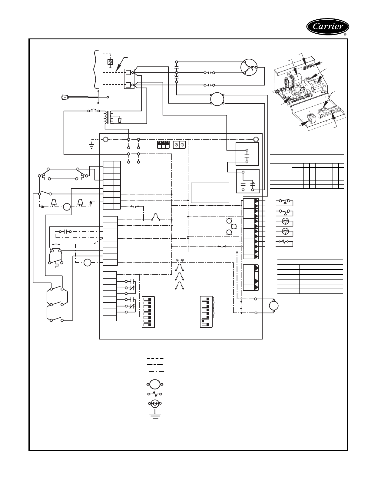
Power Supply
Refer to Data Plate
conductors only.
Refer to Disconnect
box for optional
power supply connection
Optional
Cord
Connection
4
5
RED
6
PBS
3
3A
YEL
YEL
RED
GRY
RED
55A
RED
6
RED
7
AL —
BM —
Cap —
CB —
CO —
CR —
DM —
FP1 —
FP2 —
HP —
LOC —
NLL —
OS —
PB —
PBS —
RVS —
Tr an s
—
UMT
—
UPM
—
WV
—
AUTOMATIC CHANGEOVER WITH DELUXE D CONTROLLER
Ground
Use copper
See Note 2
YEL
UMT
1
ORG
YEL
3
DM
ORG
YEL
RED
TIME CLOCK
CLOSED=UNOCCUPIED
OS
WHT
NLL
GRY
PBS
6A
7A
GRY
Alarm Relay Contacts
Blower Motor
Capacitor
Circuit Breaker
Condensate Overflow
Compressor Relay
Damper Motor
Sensor, Water Coil Freeze Protection
Sensor, Air Coil Freeze Protection
High-Pressure Switch
Loss of Charge Pressure Switch
Night Low Limit Thermostat
Override Switch
Power Terminal Block
Push Button Switch
Reversing Valve Solenoid
Transformer
Unit Mounted Thermostat
Unit Performance Monitor
Water Valve
ORG
NOTE 7
2
BRN
BRN
WV
SEE
YEL
GRY
RED
BRN
WHT
GRY
CB
YEL
L2
L1
L2 (ribbed)
L1 (plain)
Trans
O/W2
AL1
Y1
Y2
W1
G
R
C
P2
AL2
NSB
ESD
OVR
P3
NO1
NC1
COM
NO2
NC2
COM
Ground
P1
R
C
H
A
R
R
ORG
230V
BLU
1
2
3
4
5
6
7
8
ACC1
RELAY
ACC2
RELAY
LEGEND
Neutral on 265V Systems
BLK
C
R
RED
BRN
(265V)
RED
(208V)
WHT
(115V)
SEE
NOTE 6
AL2 DRY
OFF ON
1
2
3
4
5
6
7
8
S1
DIP SWITCH
PACKAGE
UPM: Disable/Enable
Unit Stage: 2/1
T'stat: Heat Cool/Heat Pump
RV on B/RV on O
Dehumid/Normal
Not Used
Boilerless: Enable/Disable
Boilerless: 40°F/50°F
2
PB
1
ALARM
RELAY
----------
>
>
H
CAP
C
F
YEL
GRY
SEE
NOTE 3
C
R
S
C
JW4
S
COM1
TEST
PINS
JW3
FP1
JW2
FP2
JW1
LP
COM2
Field Line Voltage Wiring
Field Low-Voltage Wiring
Printed Circuit Trace
Optional Low Voltage
Wiring
Relay Contactor Coil
Solenoid Coil
Thermistor
Ground
Mate-N-Lock
6
RED
CR
2
BLK
BRN
D
Microprocessor
Control Logic
STATUS
FAULT
SEE
Low
NOTE 4
Low
N.O.
ON
OFF
1
2
3
4
5
6
7
8
S2
DIP SWITCH
PACKAGE
BLU
8
RED
4
BLK
B (HIGH)
2
BM
A (LOW)
1
GRY
TEST
RV
RELAY
ACC1
Functions
ACC2
Functions
H: hi fan/dehumid
Not Used
Compressor
S
R
C
BLK
RED
FAN ENABLE
COM
NO
COM
NO
G
Y
R
NOTES:
1. Compressor and Blower Motor thermally pro-
RELAY
HP
LOC
FP1
FP2
RV
CO
P7
24V
DC
EH1
EH2
COMPR
RELAY
P6
FAN
SPEED
RELAY
NC
1
2
3
4
5
6
7
8
9
CCG
CC
RED
RED
RED
BLU
BRN
GRY
GRY
VIO
VIO
BRN
ORG
Not Used
BRN
YEL
Deluxe
TERMINALS
CR
PB
Cap
D
UMT
PUSH BUTTON SWITCH AT TRIBUTES
X = CLOSED O = OPEN
1 2345678
1A 1B 2A 3A 4A 5A 6A 7A 8A
XOOOOOOOO
STOP
FAN ONLY
LOW FAN
HIGH FAN
XOOOOX OOO
XOOXXOXOO
XOOXXOOXX
HP
LOC
SEE
FP1
NOTE 4
FP2
RVS
BLOWER MOTOR WIRING
UNIT SIZE POLE A POLE B
007 5 3
009 5 3
012 5 4
015 4 3
019 4 3
1
0
Ground
CR
Transformer
PBS
tected internally.
2. All wiring to the unit must comply with NEC and
local codes.
3. Transformer is wired to 115V (WHT) lead for
115/1/60 units, 265V (BRN) Lead for 265/1/60
units or 208V (RED) Lead for 208/1/60. For
230/1/60 switch RED and ORG Leads at L1 and
insulate RED lead. Transformer is energy limiting
or may have circuit breaker.
4. FP1 Thermistor provides freeze protection for
WATER. When using ANTI-FREEZE solutions,
cut JW3 jumper.
5. Typical unit-mounted thermostat wiring shown.
6. 24 V Alarm Signal shown. For Dry Alarm Contact, cut AL2DRY (JW4) Jumper and Dry Contact
will be available between AL1 and AL2.
7. Transformer secondary ground via Deluxe D
board standoffs and screws to Control Box.
(Ground available from top two standoffs as
shown.)
OS
29
Page 30
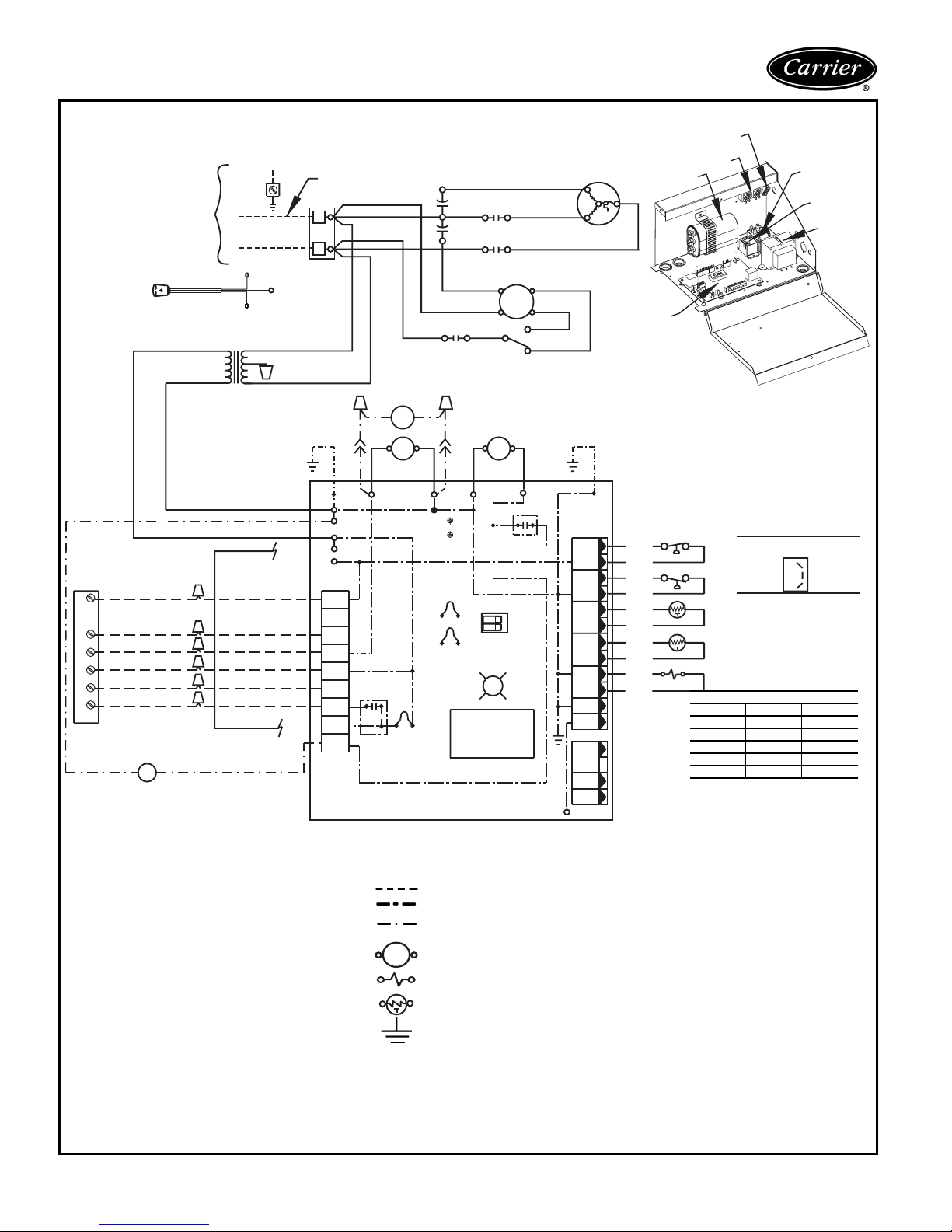
Typical wiring schematics (cont)
REMOTE-MOUNTED THERMOSTAT WITH COMPLETE C CONTROLLER
Power Supply
Refer to Data Plate
Use copper conductors only.
See Note 2
Refer to Disconnect
box for optional
power supply connection
Optional
Cord
Connection
Typical Heat Pump T-stat
SEE NOTE 5
Class 1 or 2
Wiring acceptable
outside control box
Y
O
G
R
C
L
BRN
WV
24V
Ground
L2
L1
L2 (ribbed)
L1 (plain)
Trans
Class 1 Wiring
required inside
control box
Compressor
Cooling
Fan
24 V AC
Common
Alarm
SEE
NOTE 7
Ground
ORG
230V
BLU
BRN
YEL
YEL
BLK
Neutral on 265V Systems
RED
PB
12
BRN
(265V)
RED
(208V)
WHT
(115V)
YEL
DM
10 1
YEL
BR
C
R
Y
Y
W
O
G
R
C
Alarm
Relay
JW1
SEE NOTE 6
AL1
AL2
A
P1
BLK
SEE
NOTE 3
ORG
BR
BRNGRY BRN
BRG
Test Pins
SEE
NOTE 4
JW3
FP1 Low Temp
JW2
FP2 Low Temp
H
CAP
C
RED
F
BLK
COM
NO
BR
BRNYEL
CCG
Microprocessor
Control Logic
6
2
BRN
YEL
BLK
BRN
Dip Switch
Off On
C
CR
2
1
CR
Compressor
Relay
G
8
4
BM
2
FSS
0
CC
UPM
1
2
Not Used
Status
LED
BLU
RED
BLK
B (HIGH)
A (LOW)
3
1
YEL
RED
Ground
PB
Complete
RED
RED
BLU
BRN
GRY
GRY
VIO
VIO
BRN
ORG
Cap
C
(LOCATED IN COMPRESSOR COMPARTMENT)
HP
LOC
SEE
FP1
NOTE 4
FP2
RVS
BLOWER MOTOR WIRING
UNIT SIZE POLE A POLE B
007 5 3
009 5 3
012 5 4
015 4 3
019 4 3
FAN SPEED SWITCH
Compressor
S
R
C
BLK
SEE
NOTE 7
1
HP
2
3
LOC
4
5
FP1
6
7
FP2
8
9
RV
10
Not UsedNot Used
12
CO
P2
24V
DC
EH1
EH2
P3
CO
CR
BR
Transformer
1
2
3
LEGEND
AL —
BM —
BR —
Cap —
CO —
CR —
DM —
FP1 —
FP2 —
FSS —
HP —
JW1 —
LOC —
P1 —
PB —
RVS —
Tran s
UPM
WV
Alarm Relay Contacts
Blower Motor
Blower Relay
Capacitor
Condensate Overflow
Compressor Relay
Damper Motor
Sensor, Water Coil Freeze Protection
Sensor, Air Coil Freeze Protection
Fan Speed Switch
High-Pressure Switch
Jumper Wire for Alarm
Loss of Charge Pressure Switch
Field Wiring Terminal Block
Power Terminal Block
Reversing Valve Solenoid
Transformer
—
Unit Performance Monitor
—
Water Valve
—
30
----------
Field Line Voltage Wiring
Field Low-Voltage Wiring
Printed Circuit Trace
Optional Low Voltage
Wiring
Relay Contactor Coil
Solenoid Coil
Thermistor
Ground
NOTES:
1. Compressor and Blower Motor thermally protected internally.
2. All wiring to the unit must comply with NEC
and local codes.
3. Transformer is wired to 115V (WHT) lead for
115/1/60 units, 265V (BRN) Lead for 265/1/
60 units or 208V (RED) Lead for 208/1/60.
For 230/1/60 switch RED and ORG Leads at
L1 and insulate RED lead. Transformer is
energy limiting or may have circuit breaker.
4. FP1 Thermistor provides freeze protection
for WATER. When using ANTI-FREEZE solutions, cut JW3 jumper.
5. Typical heat pump thermostat wiring shown.
Refer to thermostat Installation Instructions
for wiring to the unit.
6. 24 V Alarm Signal shown. For Dry Alarm
Contact, cut JW1 Jumper and Dry Contact
will be available between AL1 and AL2.
7. Transformer secondary ground via Complete C board standoffs and screws to Control Box. (Ground available from top two
standoffs as shown.)
Page 31
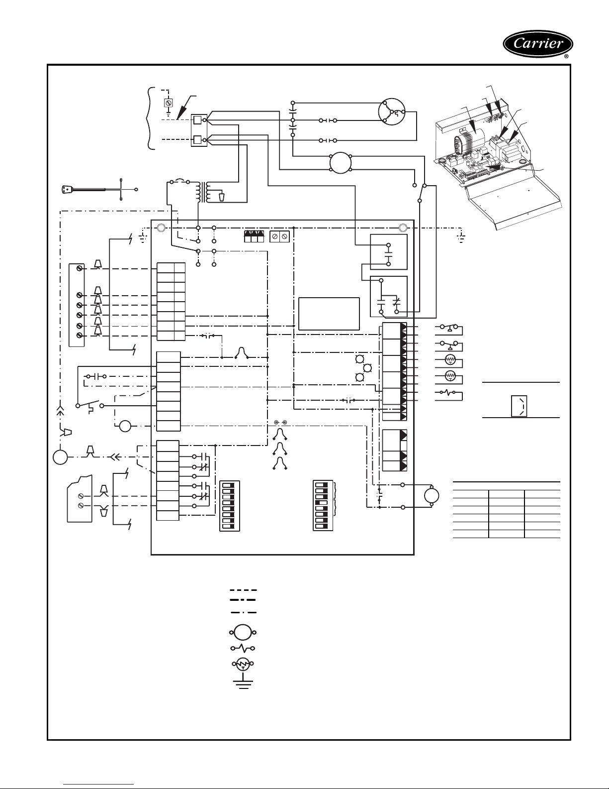
Power Supply
Refer to Data Plate
Use copper
conductors only.
See Note 2
Refer to Disconnect
box for optional
power supply connection
Optional
Cord
Connection
BRN
Class 1 or 2
Wiring acceptable
outside control box
Y
O
G
R
C
X1
Typical Heat
Pump T-stat
SEE NOTE 5
BRN
CLOSED=UNOCCUPIED
NLL
BRN
ORG
YEL
DM
OV
OV
OVERRIDE
WITH DIGITAL T-STAT
AL —
BM —
Cap —
CB —
CO —
CR —
DM —
FP1 —
FP2 —
FSS —
HP —
LOC —
NLL —
P1 —
PB —
RVS —
Tr an s
UPM
WV
Alarm Relay Contacts
Blower Motor
Capacitor
Circuit Breaker
Condensate Overflow
Compressor Relay
Damper Motor
Sensor, Water Coil Freeze Protection
Sensor, Air Coil Freeze Protection
Fan Speed Switch
High-Pressure Switch
Loss of Charge Pressure Switch
Night Low Limit Thermostat
Field Wiring Terminal Block
Power Terminal Block
Reversing Valve Solenoid
Transformer
—
Unit Performance Monitor
—
Water Valve
—
L2 (ribbed)
L1 (plain)
SEE
NOTE 7
Class 1 Wiring
required inside
control box
Compressor
Cooling
Fan
24 V AC
Common
Alarm
RED
TIME CLOCK
BRN
WHT
YEL
WV
YELYEL
OVERRIDE
OVERRIDE
REMOTE-MOUNTED THERMOSTAT WITH DELUXE D CONTROLLER
Ground
RED
Ground
L2
L1
P1
Y1
Y2
W1
O/W2
G
R
C
AL1
P2
AL2
R
NSB
C
ESD
OVR
H
A
P3
R
NO1
NC1
COM
NO2
NC2
COM
R
CB
YEL
1
2
3
4
5
6
7
8
ACC1
RELAY
ACC2
RELAY
LEGEND
Neutral on 265V Systems
C
R
RED
BLK
ORG
230V
SEE
NOTE 6
AL2 DRY
OFF ON
1
2
3
4
5
6
7
8
S1
DIP SWITCH
PACKAGE
Trans
ALARM
RELAY
2
PB
1
BLU
----------
H
C
F
BRN
(265V)
RED
(208V)
WHT
SEE
(115V)
NOTE 3
S
S
TEST
PINS
C
JW3
FP1
JW2
FP2
JW1
LP
COM2CRCOM1
JW4
UPM: Disable/Enable
Unit Stage: 2/1
T'stat: Heat Cool/Heat Pump
RV on B/RV on O
Dehumid/Normal
Not Used
Boilerless: Enable/Disable
Boilerless: 40°F/50°F
Field Line Voltage Wiring
Field Low-Voltage Wiring
Printed Circuit Trace
Optional Low Voltage
Wiring
Relay Contactor Coil
Solenoid Coil
Thermistor
Ground
CAP
RED
BLK
BRN
YEL
Microprocessor
Control Logic
SEE
Low
NOTE 4
Low
N.O.
OFF
DIP SWITCH
PACKAGE
6
2
ON
S2
CR
2
1
D
STATUS
FAULT
1
2
3
4
5
6
7
8
BLU
8
RED
4
BLK
B (HIGH)
BM
A (LOW)
GRY
GRY
G
TEST
R
RV
RELAY
ACC1
Functions
ACC2
Functions
H: hi fan/dehumid
Not Used
Compressor
S
R
C
BLK
RED
3
FSS
2
FAN ENABLE
RELAY
COM
NO
COM
FAN
SPEED
RELAY
NC
NO
1
HP
2
3
LOC
4
5
FP1
FP2
RV
10
CO
12
P7
24V
DC
EH1
EH2
P6
COMPR
RELAY
6
7
8
9
CCG
BRN
CC
YEL
Y
NOTES:
1. Compressor and Blower Motor thermally protected
internally.
2. All wiring to the unit must comply with NEC and local
codes.
3. Transformer is wired to 115V (WHT) lead for 115/1/60
units, 265V (BRN) Lead for 265/1/60 units or 208V
(RED) Lead for 208/1/60. For 230/1/60 switch RED
and ORG Leads at L1 and insulate RED lead. Transformer is energy limiting or may have circuit breaker.
4. FP1 Thermistor provides freeze protection for
WATER. When using ANTI-FREEZE solutions, cut
JW3 jumper.
5. Typical heat pump thermostat wiring shown. Refer to
thermostat Installation Instructions for wiring to the
unit.
6. 24 V Alarm Signal shown. For Dry Alarm Contact, cut
AL2DRY(JW4) Jumper and Dry Contact will be available between AL1 and AL2.
7. Transformer secondary ground via Deluxe D board
standoffs and screws to Control Box. (Ground available from top two standoffs as shown.)
1
GRY
RED
RED
BLU
BRN
GRY
GRY
VIO
VIO
BRN
ORG
Not Used
CR
Ground
PB
Cap
SEE
NOTE 7
BLK
HP
LOC
SEE
FP1
NOTE 4
FP2
FAN SPEED SWITCH
(LOCATED IN COMPRESSOR COMPARTMENT)
RVS
1
BLOWER MOTOR WIRING
UNIT SIZE POLE A POLE B
0
007 5 3
009 5 3
012 5 4
015 4 3
019 4 3
1
2
3
CR
Transformer
Deluxe
D
31
Page 32
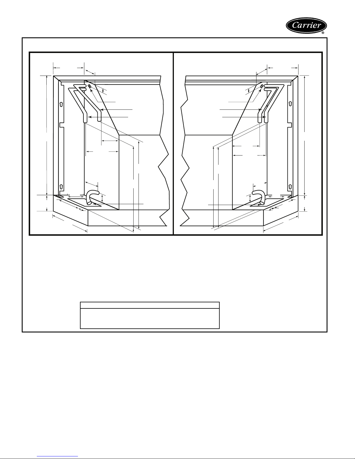
Typical piping and wiring
LEFT HAND RIGHT HAND
5.5 (140)
3.5 (89)
STANDARD UNIT
3.5
(89)
5.5 (140)
21
(533)
3
(76)
7.13
(181)
9.5
(241)
3.5
(89)
(38)
1.5
3.5 (89)
3.16 (80)
1 (25)
Power Supply In
2 (51)
1.25
(32)
Power Supply In
Water Out Water Out
Water In
13
(330)
13
(330)
Condensate
Drain
Subbase available only on bottom return units
No condensate trap required
Water In
Condensate
Drain
(330)
.
13
13
(330)
1 (25)
1.5
(38)
2
(51)
3.5 (89)
(25)
21
(533)
1
3.5
(89)
(181)
1.5
(38)
7.13
9.5
(241)
(76)
3
Electrical wiring and water piping may enter the cabinet either:
1. From below, passing up through the 7
2. From behind, passing through the 41/2-in. (114) wide opening in the rear cabinet.
1
/8-in. (181) x 31/2-in. (89) opening in the subbase.
3. Be sure adequate room is given for any accessories like valves, disconnect switches, etc.
4. All measurements in inches. Measurements in parentheses are in millimeters.
Piping Connections Available
Female Pipe Thread
Sweat Copper Pipe (shown above)
Motorized Water Valve (see separate submittal page)
Male Pipe Thread
32
Page 33
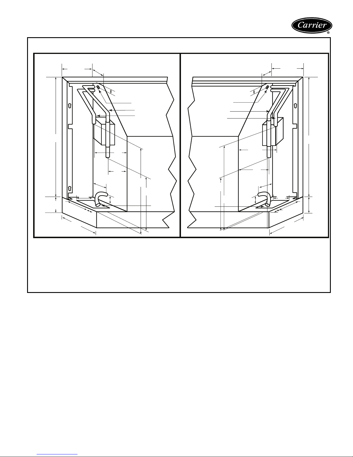
WITH MOTORIZED SHUT-OFF VALVE
LEFT HAND RIGHT HAND
5.5 (140)
3.5
(89)
3.5 (89)
5.5 (140)
21
(533)
3
(76)
7.13
(181)
9.5
(241)
3.5
(80)
1.5
(38)
3.16
(83)
1 (25)
Power Supply In
Water Out
Water In
3.5
(89)
2
(51)
13
(330)
10
(254)
1.25
(32)
Condensate
Drain
Condensate
Subbase available only on bottom return units
No condensate trap required
Power Supply In
Water Out
Water In
13
(330)
(254)
Drain
.
1 (25)
21
(533)
3.5 (89)
2
(51)
1 (25)
3.5
10
1.5
(38)
(89)
1.5
(38)
9.5
(241)
7.13
(181)
(76)
3
Electrical wiring and water piping may enter the cabinet either:
1. From below, passing up through the 7
2. From behind, passing through the 4
1
/8-in. (181) x 31/2-in. (89) opening in the subbase.
1
/2-in. (114) wide opening in the rear cabinet.
3. All measurements in inches. Measurements in parentheses are in millimeters.
4. Be sure adequate room is given for any accessories like valves, disconnect switches, etc.
33
Page 34
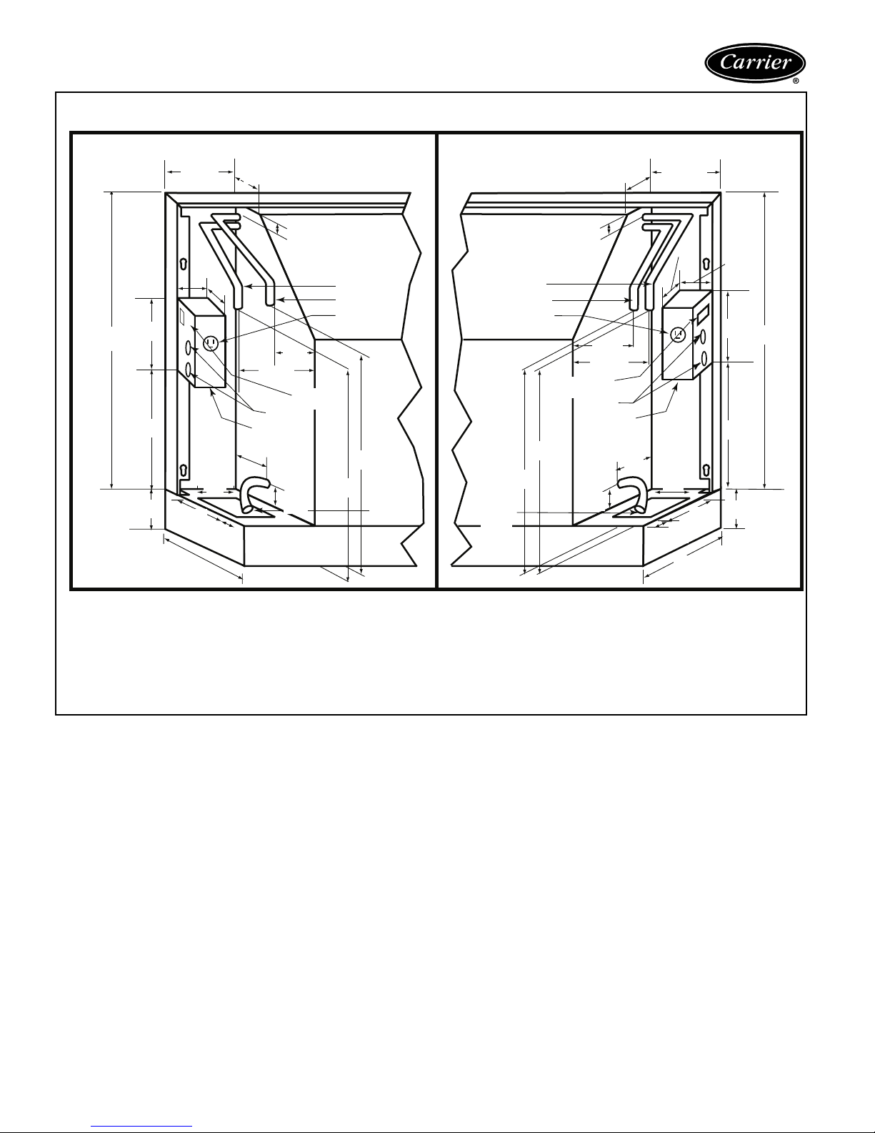
Typical piping and wiring (cont)
WITH OPTIONAL DISCONNECT SWITCH (FUSED OR UNFUSED) AND/OR RECEPTACLE
LEFT HAND RIGHT HAND
5.5 (140)
3.5
(89)
3.5
(89)
5.5 (140)
21
(531)
7.5
(178)
7
(178)
3
(76)
4.25
(108)
7.13
181)
9.5
(241)
3.25
(83)
3.5
(89)
1.5
(38)
3.5 (89)
Fuses
Power
Supply In
3.16 (83)
1
(25)
Water In
Water Out
Receptacle
(51)
2
Disconnect
Switch
13
(330)
13
1.25
(32)
(330)
Condensate
Drain
Subbase available only on bottom return units
No condensate trap required
Water In
Water Out
Receptacle
Condensate
Drain
(330)
.
1
(25)
2 (51)
3.5 (89)
Disconnect
Switch
Fuses
Power
Supply In
13
(330)
13
(38)
1.5
(25)
1
3.5
(83)
1.5
(38)
9.5 (241)
3.25
(83)
7.13
(181)
4.25
(108)
7.5
(191)
7
(178)
(76)
21
(533)
3
Electrical wiring and water piping may enter the cabinet either:
1. From below, passing up through the 7
2. From behind, passing through the 4
3. Be sure adequate room is given for any accessories like valves, disconnect switches, etc.
1
/8-in. (181) x 31/2-in. (89) opening in the subbase.
1
/2-in. (114) wide opening in the rear cabinet.
4. All measurements in inches. Measurements in parentheses are in millimeters.
34
Page 35

Guide specifications
Console Water Source Heat Pumps
HVAC Guide Specifications
Size Range:
Carrier Model Number:
Part 1 — General
1.01 SYSTEM DESCRIPTION
A. Install Water Source Heat Pumps, as indicated on
the plans with capacities and characteristics as listed
in the schedule and the specifications that follow.
Units shall be Carrier model 50KQA (standard temperature range 60 F to 95 F) or model 50KQD (low
temperature range 40 F to 110 F).
B. Units shall be individually packaged with wooden
skid covered with protective corner posts and plastic
stretch wrapping for maximum protection.
1.02 QUALITY ASSURANCE
A. All equipment listed in this section must be rated in
accordance with ARI and CSA. The units shall have
ARI, CSA labels.
B. All units shall be factory tested under normal operat-
ing conditions at nominal water flow rates. Units
which are tested without water flow rates are not
acceptable.
Part 2 — Product
2.01 EQUIPMENT
A. Heat Pump Assembly:
Factory-tested and assembled single-piece packaged
heating and cooling heat pump units shall be factory
wired, charged with non-CFC R-22, contain
refrigerant-to-water heat exchanger, air-to-refrigerant
heat exchanger, 4-way reversing valve, fan motor
assembly, compressor, TXV metering device, and all
internal controls and safety devices.
B. Unit Cabinet:
6,800 to 17,600 Btuh
Cooling Capacity
8,600 to 21,000 Btuh
Heating Capacity
50KQA, KQD
1. The cabinet shall be constructed of heavy gage
steel with welded corner bracing. A removable
front cabinet allows easy service access to the
chassis. The cabinet shall have a 30-degree
sloped top with an aluminum rigid bar type discharge grille.
2. An access door shall be provided to cover the
swing down control section. For all capacities of
the Console Heat Pump, the cabinet shall be
one size (48-in. L x 9
3. Options include a locking control panel for
added security; a bottom or front return with
left or right hand configurations for ease of
installation. Available with 3 or 5 in. subbase,
with or without motorized damper.
4. The cabinet shall be powder painted.
1
/2- in. W x 24-in. H).
C. Fan and Motor Assembly:
The fan motors shall be multi-speed permanently
lubricated, PSC (permanent split capacitor) type
with thermal overload protection. To facilitate field
service all units shall have a slide out fan deck and
quick electrical disconnect.
D. Refrigerant Components:
1. Units shall have a sealed refrigerant circuit including a hermetic compressor, a refrigerant metering device, a finned tube refrigerant-to-air heat
exchanger, a reversing valve, a coaxial (tube-intube) refrigerant-to-water heat exchanger, and
safety controls including a high-pressure sensor, a
loss-of-charge sensor to protect against loss of
refrigerant, and low water temperature (freezestat) sensor.
2. Rotary compressors shall have thermal overload protection and shall be located in an
insulated compartment to minimize sound
transmission. Units shall have the compressor
mounted on isolators to reduce noise and vibration transmission.
3. Refrigerant-to-air heat exchangers shall utilize
enhanced aluminum fins and rifled copper tube
construction rated to withstand 425 psi refrigerant working pressure.
4. Refrigerant-to-water heat exchangers shall be of
copper inner water tube and steel refrigerant
outer tube design rated to withstand 450 psi
working refrigerant pressure.
5. Reversing valve shall be four-way solenoidactivated refrigerant valves which shall fail to
heating operation. If the unit fails to cooling a
low-temperature thermostat must be provided
to prevent over-cooling of the room.
6. Optional coaxial water-to-refrigerant heat
exchangers shall be cupronickel.
E. Controls and Safeties:
Units which may be reset at the disconnect switch
only shall not be acceptable.
1. Electrical:
A control box shall be located within the unit
and shall contain controls for compressor,
reversing valve and fan motor operation.
2. Piping:
a. Copper tubes with a
shall be provided on the supply and return
water connections for the purpose of forming a sweat connection to field-supplied distribution piping.
b. Optional threaded connections: A
male or female pipe threaded fitting shall be
factory mounted on the supply and return
water connections.
5
/8-in. OD dimension
1
/2-in.
35
Page 36

Guide specifications (cont)
3. Unit Controls:
Safety devices on all units shall include low-
pressure sensor or loss-of-charge switch, highpressure switch, low water temperature sensor,
and condensate overflow switch.
4. The standard Complete C electronic control
system shall interface with the unit mounted or
remote heat pump (Y,O) wall thermostat
(mechanical or electronic). The control system
shall have the following features:
a. 50 VA transformer.
b. Anti-short cycle time delay on compressor
operation; time delay shall be 5 minutes
minimum.
c. Random start on power-up.
d. Low voltage protection.
e. High voltage protection.
f. Condensate overflow shutdown.
g. Unit shutdown on low refrigerant pressures.
h. Unit shutdown on high or low water temper-
ature (selectable for antifreeze solutions).
i. Option to reset unit at thermostat or discon-
nect. Fault type shall be retained in memory
if reset at thermostat.
j. Automatic intelligent reset. Unit shall auto-
matically restart 5 minutes after shutdown if
the fault has cleared. Should a fault occur
3 times sequentially, then lockout will occur.
k. Ability to defeat time delays for servicing.
l. Light-emitting diode (LED) to indicate high
pressure, low pressure, improper voltage,
water coil freeze protection, air coil freeze
protection, condensate overflow, and con-
trol status.
m. Unit Performance Monitor to indicate ineffi-
cient operating conditions prior to unit
lockout.
n. Remote fault type indication at thermostat.
o. Single harness connection for all safety
devices.
p. Selectable 24-v or pilot duty dry contact
alarm output.
q. 24-v output to cycle a motorized water valve
with compressor contactor.
r. The control box components shall be
easily accessible with a swing out control
compartment.
s. Standard unit-mounted MCO (manual
changeover) thermostat operating controls
shall consist of temperature setting dial
knob, push button switches for Stop, Fan
only, Hi Cool, Lo Cool, Hi Heat, Lo Heat.
Unit-mounted thermostats shall have a
remote sensor for sensing the return-air
temperature.
5. The optional Deluxe D electronic control shall
have all the features of the Complete C control,
with the following additional features:
a. 75 VA transformer.
b. A removable thermostat connector.
c. Random start on return from night setback.
d. Minimized reversing value operation for
extended life and quiet operation.
e. Night setback control from low temperature
thermostat, with 2-hour override initiated by
a momentary signal from the thermostat.
f. Dry contact night setback output for digital
night setback thermostats.
g. Ability to work with heat/cool (Y, W)
thermostats.
h. Ability to work with heat pump thermostats
using O or B reversing valve control.
i. Single grounded wire to initiate night set-
back or emergency shutdown.
j. Boilerless system control can switch auto-
matically to electric heat at low loop water
temperature.
k. Control board shall allow up to 3 units to be
operated from one thermostat without any
auxiliary controls.
l. A relay to operate an external damper. The
control to be such that the damper will not
open until 30 minutes after the unit comes
back from Unoccupied mode.
m. Fan speed selection at thermostat.
n. A relay to restart a central pump or control a
24-v motorized water valve.
o. Intelligent fan speed selection based upon
thermostat demand and/or dehumidistat
signal.
6. Carrier PremierLink™ Controller:
This control will function with CCN and Com-
fortVIEW™ software. It shall also be compatible
with ComfortLink™ controllers. It shall be
ASHRAE 62-99 compliant and Internet ready.
It shall accept a CO
space and be Demand Control Ventilation
(DCV) ready. The communication rate must be
38.4K or faster.
7. Optional Controls:
a. Unit-mounted ACO (automatic changeover)
thermostat operating controls shall consist
of temperature setting dial knob, push button switches for Stop, Fan only, Hi fan, Lo
fan. Unit-mounted thermostats shall have a
remote sensor for sensing the return-air
temperature.
sensor in the conditioned
2
36
Page 37

b. Units designed for connection to remote wall
mounted thermostat shall be wired such that
the operating controls are at the thermostat.
The controller shall be provided with a low
voltage field wiring terminal block. The control scheme shall accommodate MCO or
ACO heat pump thermostats with Y, G, and
O outputs. An alternate controller shall be
available from the factory to accommodate
the Heat/Cool thermostats.
c. Motorized water valves shall be factory
installed and wired. The valve shall remain
open when there is a cooling or heating
demand and the compressor is running. The
valve shall close when the compressor stops
after satisfying the demand or due to lockout
condition.
d. Fresh air dampers shall be motorized with a
spring return. The damper shall open when
Cooling or Heating mode selection is made
from the unit-mounted switches. With a
remote thermostat, the damper shall open
any time the fan is in operation.
e. Night low limit thermostats shall include a
unit-mounted thermostat sensing space temperature. Should the space temperature fall
below the limit, the night low limit thermostat shall start the fan and compressor operation in Heating mode.
f. Units with the unit-mounted thermostat shall
include a 2-hour override function. The
override switch shall be readily accessible. In
override mode the unit operation shall be
the same as in occupied mode. Override
mode shall be terminated automatically at
the end of a 2-hour period.
g. The unit shall be provided with a factory-
wired cord and plug set conforming to
NEMA (6-20P, 7-20P, or 6-30P).
F. Electrical Requirements:
1. A control box shall be located within the unit
compressor compartment and shall contain a
50 va transformer, 24-volt activated, 3-pole
compressor contactor, terminal block for
thermostat wiring and solid-state controller for
complete unit operation. Electro-mechanical
operation WILL NOT be accepted.
2. Units shall be nameplated for use with timedelay fuses or HACR circuit breakers.
3. Unit controls shall be 24-volt and provide heating or cooling as required by the remote
thermostat.
G. Special Features:
1. Aquazone™ Thermostat Controls (for use with
remote thermostat units):
a. Programmable multi-stage thermostat with
7-day clock, holiday scheduling, large backlit
display and remote sensor capability.
b. Programmable 7-Day Light-Activated Ther-
mostat offers occupied comfort settings with
lights on, unoccupied energy savings with
lights off.
c. Programmable 7-Day Flush-Mount Thermo-
stat offers locking coverplate with tamper
proof screws, flush to wall mount, dual point
with adjustable deadband, O or B terminal,
and optional remote sensor.
d. Programmable 5-Day Thermostat offers
2-stage heat, 2-stage cool, auto changeover,
5-minute built-in compressor protection, locking cover included.
e. Non-programmable Thermostat with 2 heat
stages, 2 cool stages, auto changeover,
5-minute built-in compressor protection, locking cover included.
2. Aquazone System Control Panel:
The panel shall coordinate, monitor, and con-
trol all WSHP units and ancillary equipment
including cooling towers, boilers, and system
pumps.
3. Fire-Rated Hose kits:
Hoses shall have a fixed MPT on one end and a
swivel with an adapter on the other end. Hose
kits shall be either stainless steel or galvanized.
4. Ball Valves (Brass Body):
Ball valves shall be for shutoff and balancing
water flow. Valves shall be available with memory, memory stop, and pressure temperature
ports.
5. Y Strainers (Bronze Body):
Strainers shall have “Y” type configuration with
a brass cap. Strainers shall have a maximum
operating pressure rating of 450 psi. Strainer
screen shall be made of stainless steel.
6. Solenoid Valves (Brass Body):
Valves shall provide slow operation for quiet
system application.
7. Hose Kit Assemblies:
Hose kits shall include a ported ball valve with
pressure temperature (P/T) plug ports, flexible
stainless steel hose with swivel and nipple.
Return hose includes a ball valve, preset measure flow (gpm) with two P/T ports, flexible
stainless steel hose with a swivel and nipple.
8. Remote Sensors:
Sensors for Aquazone flush-mount thermostats
shall be available.
9. PremierLink™ accessories:
PremierLink accessories shall provide a fully
integrated DDC system. Accessories include
supply air temperature sensors, communicating
room sensors, CO
sensors, and linkage ther-
2
mostats.
37
Page 38

Page 39

Page 40
Carrier Corporation • Syracuse, New York 13221 5-03
Book 1 4
Manufacturer reserves the right to discontinue, or change at any time, specifications or designs without notice and without incurring obligations.
Ta b 5 a 5 a
Book 1
New Pg 40 Catalog No. 525-00049 Printed in U.S.A. PC 111 Form 50KQ-6PD
Ta b 1 IP 4 a
Replaces: 50KQ-5PD
 Loading...