

Page 1

Carrier
INSTALLATION
SUPPLEMENTARY INSTRUCTION
FOR 50K CONOENSERLESS UNITS
50K
O
CN
8)
CJ
O
M
tì
O
bo
tì
The following items are included in the base unit for
field installation:
a. Discharge Line Assembly
b. Moisture and Liquid Indicator
c. Filter-drier
d. Crankcase Heater Relay Assembly
e . Condenser Fan Relay Assembly
NOTE: One each of the above items is used on
all units, except the 50K16-2 compres
sor model which has two each.
Install this unit in accordance with the instructions
in the Unit Installation Instruction Book (50K8-1005
Rev. ) except for the following items .
AIR-COOLED CONDENSER LOCATION
The air-cooled condenser should not be located more
than 60 feet above, or 15 feet below the base unit.
Cneck the installation booklet with the condenser for
installation details.
In order to prevent condensed liquid refrigerant or
oil from causing damage to the compressor, install
a trap in the vertical discharge line near the com
pressor. The trap may be installed within or ad
jacent to the base unit chassis. The height of the
trap (or loop) should be 6 inches for every 10 feet
of vertical discharge line. If the height of the ver
tical discharge line is such as to make a single trap
impractical, the loop can be replaced by a check
valve or several traps.
When installing refrigerant piping make certain it
is well supported. Install piping with sufficient flex
ibility to make sure line vibrations are not trans
mitted to the building.
The openings in the chassis normally used for the
water-cooled condenser water piping may be used to
bring the lines into the unit.
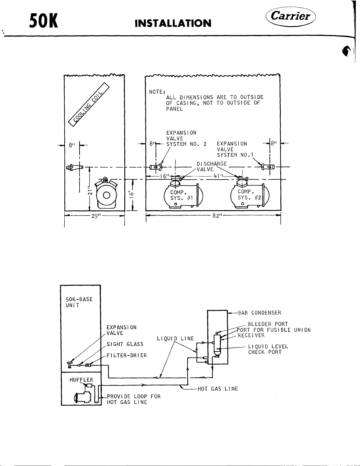
Install the discharge line assembly, filter-drier and
the moisture and liquid indicator in each circuit
within the chassis of the base unit. Locate the filterdrier and the moisture and liquid indicator in the
liquid line just before the liquid line enters the
expansion valve. The moisture and liquid indicator
goes between the filter-drier and the expansion
valve.
0)
TD
o
O
P
OT
U
d
w
(U
T3
o
O
CRANKCASE HEATERS
One crankcase heater (230 volt, 1 phase, 60 cycle)
will be factory installed on the outside of the bottom
plate of each compressor. The crankcase heater
elements replace the need for the liquid lines sole
noid valves. Each crankcase heater has 36 inch
leads for wiring in the field.
REFRIGERANT PIPING
Install the hot gas and liquid line between the base
unit and the external condenser for each system be
ing careful to connect the correct components in
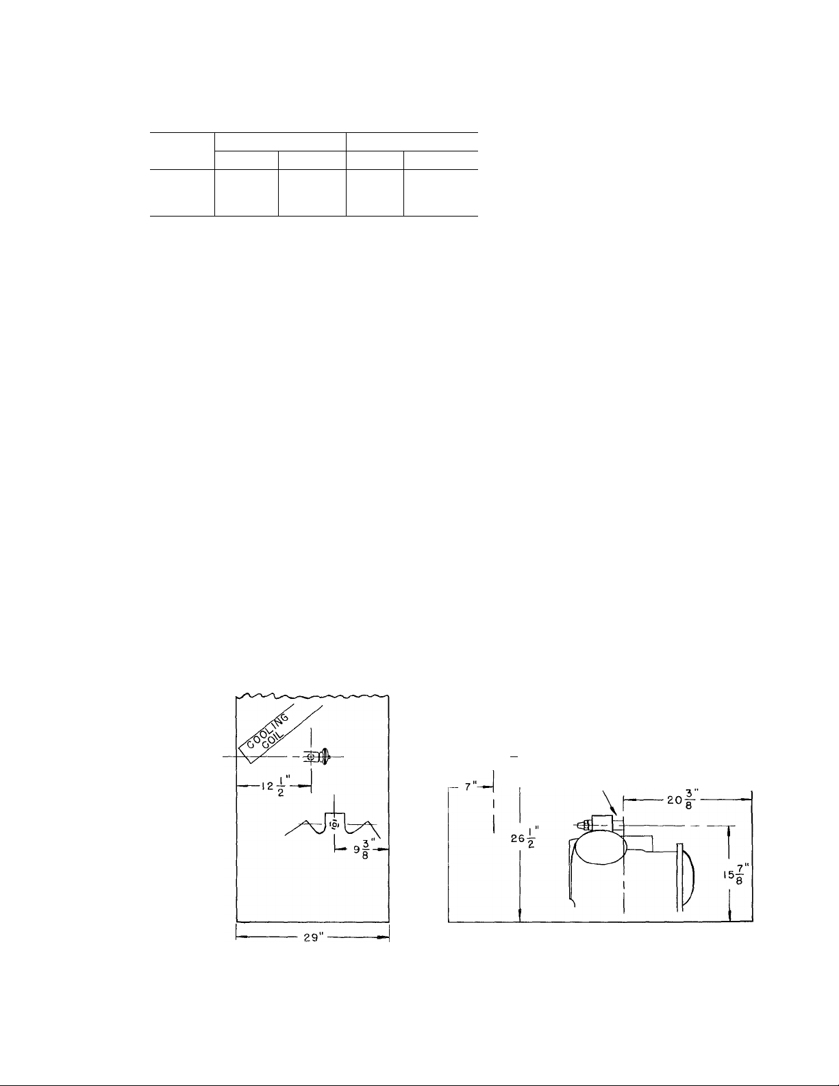
each system. Fig. 1 through 4 shows the location
of the connections at the base unit. Fig. 5 through
7 shows the schematic piping layout for the various
units when connected with the 9AB Air-Cooled Con
denser. Table 2 shows the connection sizes at the
base unit and recommends line sizes for various
refrigerant line lengths . Consult the Installation
Instructions of the condenser used and Part 3
of the System Design Manual for piping details
and line sizes when greater lengths are used.
PRESSURE RELIEF PROTECTION
Refrigerant pressure relief protection must be pro
vided for each system at the time of installation of
the unit. A suitable fusible union, a liquid line soft
solder joint within the base unit, or a rupture disc
(Chicago Code) may be used depending on local
codes, etc.
The 9AB6 receiver is provided with a 3/8" FPT fitting
for the installation of a fusible union or rupture disc.
The Cerro De Pasco Co. fusible union No. 5160-1
or No. 5250-1 (melting point 197 F or 203 F), Carrier
Part No. EK41JN200 is suitable; check local codes.
HEAD PRESSURE CONTROL
A condensing pressure (head pressure) control acces
sory package is available for use with the 9AB conden
sers . Consult the 9AB Instruction Sheets for details.
©
Carrier Corporation 1960
Litho in U.S. A. 12-60
50K8-1415
Page 2
50K
Unit
INSTALLATION
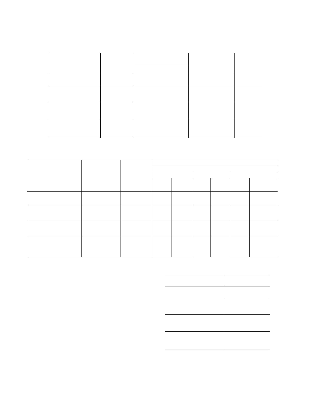
TABLE 1
Compressor
Circuit No
Model
Location
Evaporator Coil
Liquid Line
Connection
Carrier
R-22
Pounds
50K8
50K12
Single Compressor
50K16
Single Compressor
50K16
2 Compressor
Discharge Line
Unit Connection
50K8
50K12
Single Compressor
50K16 (Ea. Circuit)
2 Compressor
7/8
7/8
7/8
(1 Circuit) 6D48
(1 Circuit)
(1 Circuit)
No. 1
No. 2
Liquid Line
Connection Line
6D68 -
6D75
6D48
6D48
TABLE 2
1/2
5/8
1/2
-
_
Left Side
Right Side
Recommended Line Sizes
20 40
Liquid
Hot
Gas
1/2 7/8
5/8
1/2
7/8
7/8
-
-
- 15
Right End 10
Left End
Linear Feet Piping
Liquid
Line
Hot Liquid Hot
Gas
1/2
5/8 1-1/8
1/2
7/8
7/8
Line
1/2
1/2
3/4
10
10
10
60
Gas
7/8
1-1/8
7/8
50K16
Single Compressor 1-1/8
REFRIGERANT CHARGE
The unit will be shipped with a 2 lb. holding charge
of Refrigerant 22. In the standard installation,
Refrigerant 22 will be used. However, on special
applications. Refrigerant 500 may be used. Con
sult your Application Engineering Data for informa
tion concerning the use of Refrigerant 500. When
Refrigerant 500 is used, change the expansion valve
to the one shown in Table 3.
REFRIGERANT CHARGE QUANTITY
During operation on Refrigerant 22 the base unit
alone requires the number of pounds shown in Table 1.
To this, add the needs for the refrigerant lines, con
densers, and receivers (if used). Stamp the number
of pounds used in the blank space provided on the
nameplate.
5/8 5/8 1-1/8 3/4 1-1/8 3/4 1-3/8
TABLE 3 - VALVES FOR R-500 SERVICE
Unit
50K8
50K12
Single Compressor
50K16
Single Compressor
50K16
2 Compressor (2) required
DUAL PRESSURESTATS
Adjust the pressurestats according to pressure shown
in Table 4.
Sporlaii Valve
PDE6G
PDE9G
PDE13G
PDE6G
Page 3
Carrier
INSTALLATION
50K
TABLE 4
High Press. Switch
Refrig.
22 284 364
500
The moisture and liquid indicator must be full of
liquid refrigerant to properly indicate the moisture
content of the refrigerant. Operate the system at
least 30 minutes before attempting to determine the
moisture reading.
The compiete refrigerant system should be evacuated
with a good vacuum pump before charging with refrig
erant. When charging, connect a cylinder of refrig
erant through a tee to a gauge and to the gauge port
on the compressor service valve. Have the cylinder
in the upright position to admit vapor only. Admit re-
refrigerant to break the vacuum in the system. Start
the compressor and modulate the valve on the cylinder
to keep the suction pressure slightly under 50 psig.
Charge the system until liquid refrigerant will bleed
from the liquid level check port on the receiver and
also until the sight glass is clear. *
Cut-In
218 265
SPORLAN SEE-ALL MOISTURE AND
CHARGING PROCEDURE
Cut-Out Cut-In Cut-Out
LIQUID INDICATOR
Low Press. Switch
83
67
46
30
NOTE* If the liquid refrigerant bleeds from the
liquid level check port on the receiver but
there is stUl flashing at the sight glass,
there is an indication that there is a re
striction in the liquid line or filter-drier.
Let the system operate for 20 minutes to balance
out and recheck the refrigerant and oil levels.
The receiver has a bleeder port at the top to bleed
non-condensables from the system. There has to
be sufficient refrigerant in the system to make a
liquid seal at the outlet of the receiver to trap the
non-condensables in the top of the receiver before
the bleeder port can be effective.
WIRING
The crankcase heater elements, heater relays, and
the condenser fan relays are to be field wired. See
Wiring Diagrams.
The crankcase heater relays are single pole, single
throw, normally closed, relays . Each crankcase
heater element is to be energized when its respec
tive compressor is "OFF.”
The condenser fan relays (S.P.S.T. Normally open)
are to be mounted per the condenser Installation In
structions . The control voltage is supplied by the
base unit. Follow the right wiring diagram so the
condenser fans wUl continue to run if the compres
sor is shut down by one of its protective devices
and the thermostat is stUl calling for cooling.
SIDE ELEVATION
FIG. 1 - LOCATION OF COMPRESSOR DISCHARGE AND LIQUID CONNECTIONS 50K8
FRONT ELEVATION
NOTE. ALL DIMENSIONS ARE TO
1 OUTSIDE OF CASING, NOT
I TO OUTSIDE OF PANEL.
EXPANSION VALVEEXPANSI
COMPRESSOR
DISCHARGE VALVE
48
Page 4
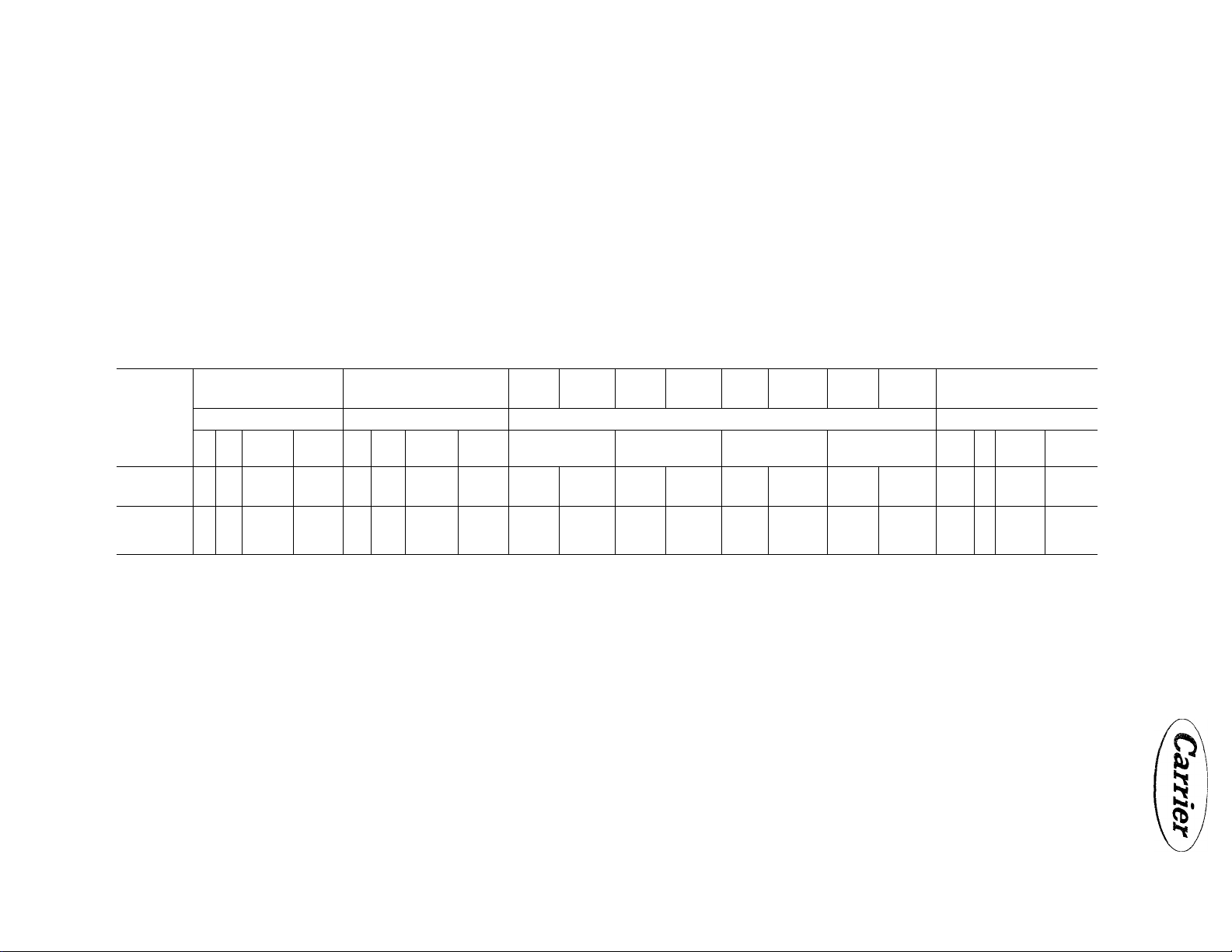
TABLE 5 - ELECTRICAL DATA
11.9
Wire
Size
Awg. No.
Locked Rotor Current
Amps.
Current
Characteristics
208/220-3-60
440-3-60 60 90
KOTES; 1. Wire sizes, lengths, fuse sizes, and dual element fuse sizes snown are for the branch circuit between the disconnect switch and the unit.
8
120 180
2. The branch circuit wire sizes and the corresponding maximum wire lengths tabulated will result in a 1% voltage drop at the nameplate full load amperage. The ware size listed and the maximum fuse sizes are
m accordance with the National Electric Code.
3. Dual element fuses can be sized much closer to the actual running current than one-time link type fuses because of the built-in lag. Thus, dual element fuses give additional motor protection against both
single phasing and locked rotor failure, should starter contacts fuse. Use dual element fuses for compressor protection on all installations. With properly selected fused disconnect switches, fuse reducers
may be required.
50K
12 16
(1 Com.p.)
250
125
16
(2 Comp.)
120
60
Full Load Current
Amps.
50K
8 12 16
24.9
11.9
(1 Comp.)16(2 Comp.)
35.7
17.5 27.2
55. 6 24.9 6
Max. Wire
Length
Ft.
8 12
8 65 6
4
12
10
8 325 6 400
Wire
Size
Awg. No
100 4
155
135 10
210 8
Max. Wire
Length
Ft.
2
Wire
Size
Awg. No.
50 K 50K
100
160
235
170
260
Max. Wire
Length
Ft.
16
(i Comp.)
4 98
2
1
8
6
4
145
185
160
250
390
Wire
Size
Awg. No.
8
6
4
12
10
8
16
(2 Comp.)
Max. Wire
Length
Ft.
80
125
195
135
210
325
Dual Element Fuse Size
12
8
35
60
17-1/2
25
Amps.
16
(1 Comp.)16(2 Comp.)
35
SO
40
17-1/2
z
(/»
>
>
o
z
Page 5
Carrier
INSTALLATION
50K
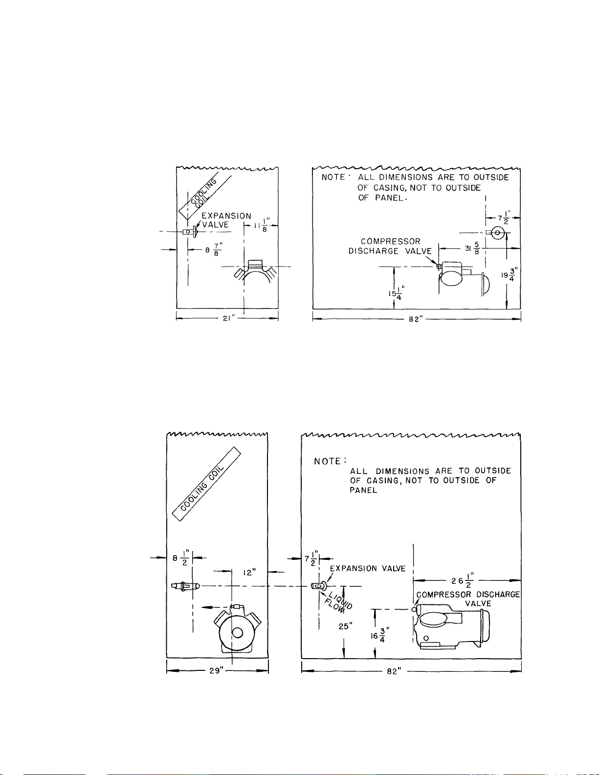
SIDE ELEVATION
FIG. 2 - LOCATION OF COMPRESSOR DISCHARGE AND LIQUID CONNECTIONS 50KI2
SIDE ELEVATION
FRONT ELEVATION
FRONT ELEVATION
FIG. 3 - LOCATION OF COMPRESSOR DISCHARGE AND LIQUID CONNECTIONS
50K16 SINGLE COMPRESSOR MODEL
Page 6
SIDE ELEVATION
FRONT ELEVATION
FIG. 4 - LOCATION OF COMPRESSOR DISCHARGE AND LIQUID CONNECTIONS
50K16 - 2 COMPRESSOR MODEL
FIG. 5 - SCHEMATIC PIPING FOR 50K8 AND 50K12 WITH ONE (1) 9AB CONDENSER
Page 7

Carrier
INSTALLATION
50K
FIG. 6 - SCHEMATIC PIPING FOR 50KI2 AND 50K16 SINGLE COMPRESSOR MODELS
WITH (2) 9AB CONDENSERS
LIQUID LINE
TO BASE UNIT
FIG. 6B - ALTERNATE ARRANGEMENT OF SCHEMATIC PIPING FOR 50K12 AND 50K16
SINGLE COMPRESSOR MODELS WITH(2) 9AB CONDENSERS
Page 8

50K
Carrier
INSTALLATION
i
FIG, 7 - SCHEMATIC PIPING FOR 50K (2-COMPRESSORS) WITH TWO (2) 9AB CONDENSERS
Page 9

Carrier
INSTALLATION
ti
50K
№
%
PIO. !> - 50K8 (440/550-3-60) CONDENSEELESS
Page 10

50K
Carrier
INSTALLATION
FIG. 10 - 50K12, SINGLE COMPRESSOR (208/230-3-60)
SCHEMATIC DIAGRAM, CONDENSERLESS
10
Page 11

Carrier
INTERNAL WIRING
FIELD WIRING
INSTALLATION
TO THERMOSTAT
NOT FURNISHED
BY CARRIER
50K
FIG. 11 - 50K12, SINGLE COMPRESSOR (208/220-3-60), CONDENSERLESS
11
Page 12

50K
INSTALLATION
220V CONTROL
CIRCUIT FOR
CONDENSER FAN
Carrier
P.L, - PILOT LIGHT
O.L. - OVERLOAD
C - COMP. STARTER
F - FAN STARTER
CH - CRANKCASE HEATER
CHR - CRANKCASE HEATER
RELAY
mFI-
^Fl-
FIG. 12 - 50K12, SINGLE COMPRESSOR (440/550-3-60)
SCHEMA.TIC DIAGRAM, CONDENSERLESS
O.L.
-U7T7
O.L.
-o
------
lilib
FAN MOTOR
COMP.
♦
12
Page 13

Carrier
INTERNAL WIRING
---------------------FIELD WIRING
INSTALLATION 50K
c
FIG. 13 - 50K12, SINGLE COMPRESSOR (440/550-3-60), CONDENSERLESS
13
Page 14

INTERNAL WIRING
FIELD WIRING
220V CONTROL CIRCUIT
FOR CONDENSER FAN RELAY
FIG. 14- 50K16, SINGLE COMPRESSOR (208/220-3-60) SCHEMATIC DIAGRAM, CONDENSERLESS
14
Page 15

Carrier
INTERNAL WIRING
INSTALLATION
SOM
€
FIG. 15 - 50K16, SINGLE COMPRESSOR (208/220-3-60) CONDENSERLESS
15
Page 16

■INTERNAL WIRING
FIELD WIRING
220V CONTROL CIRCUIT
SELECTOR SWITCH
FIG. 16 - 50K16, SINGLE COMPRESSOR (440/550-3-60) CONDENSERLESS
16
Page 17

INTERNAL WIRING
FIELD WiRiNG
3
.
>
>
-I
o
FIG 17- - 50K16, TWO COMPRESSOR (208/220-3-60) CONDENSERLESS
i/1
Page 18

Page 19

FILING INSTRUCTIONS
BOOK
MAJOR TAB
(UED) (UED)
Packaged Packaged Units
Equipment
(Installation and
Service)
MINOR TAB
Commercial and
Industrial Units
THIS ISSUE
50K8-I415
1-20
12-60
SUPERSEDES
50K8-1405
1-18
9-59
50K8-1415
12-60
 Loading...