

Carrier 50JZ036310, 50JZ042300, 50JZ048300, 50JZ036300, 50JZ030310 Installation Guide
...
HFATUNG & COOLING
%isitx__ _.¢arrier.com
Installation, Start-Up and Service instructions
50JZ 7-t4 kW (024-048)
SingMe-Package 50Hz Heat Pump Units
with Puron® (R-410A) Refrigerant
NOTE: Read the entire instruction manual be%re starting the
installation.
TABLE OF CONTENTS
SAFETY < ONSIDERATIONS 1
Introduction 2
Receiving and Installation .............................................................. 2
(heck Equipment ...................................................................... 2
Identify Unit ........................................................................ 2
Inspect Shipment ................................................................. 2
Provide -Unit Support ................................................................ 2
Roof Curb ............................................................................ 2
Slab Mount ..................................... 2
Ground Mount .................................... 2
Provide Clearances ................................... 2
Rig and Place Unit ................................... 3
Inspection ..................................... 4
Installation .......................................... 4
Select and Install Ductwork ........................... 5
Converting Horizontal Discharge Units To
Downflow (Vertical) Discharge Units ................. 7
Provide for Condensate Disposal 7
Install Electrical Connections ................................................... 9
High-Voltage Connections .......................... 9
Routing Powm Leads into Lnit .................... 1l
Connecting Ground Lead to Ground Lug ............. 1l
Routing Control Power Wires (24-V) i 1
PRE-START-UP !4
START-UP 14
(beck f_r Refrigerant Leaks 14
Start-Up Adjustments 14
Checking Cooling and Heating Control Operation .......... 14
Checking and Adjusting Refi'igerant Charge .................... 16
Refi'igerant Charge ........................... 16
No ( harge .................................... !6
Low Charge Cooling ........................... 16
Heating Mode Change 16
To Use Cooling Charging Charts i6
Indoor Airflow and Airflow Adjustments ........................ 16
Defiost ( ontrol ....................................................................... 18
Quiet Shift ..................................... 18
Defiost ........................................ !8
MAINTENANCE .................................... 20
Air Filter .......................................... 20
Indom Blower and Motor ........................... 21
Outdoor (oil, Indoor Coil, and Condensate D*ain......... 21
Outdoor Fan ...................................... 2l
Eleckical Controls and Wiring ...................... 22
Refrigerant Circuit ................................. 22
Indoor Airflow ................................... 22
PURON_R:Systems Items .......................... 22
System Infbnamtion .............................. 24
Phase Monitor Control .......................... 24
Loss of Charge S_itch 24
Check Defiost Them_ostat 24
TROL BLESHOOTING ............................................................... 24
Start°L p Checklist ........................................................................ 24
NOTE TO INSTALLER READ THESE INSTRUCTIONS
CAREFULLY AND COMPLETELY befbre installing this unit.
Also, nmke sure the Owner's Manual and Se*vice Instructions are
left with the unit afle* installation
SAFETY CONSIDERATIONS
Installation and servicing of air-conditioning equipment can be
hazardous due to system pressure and electrical components Only
trained and qualified personnel should install, repair, or service
air-conditioning equipment.
Untrained personnel can perfbrm basic nmintenance functions of
cleaning coils and filters. All other operations should be performed
by trained service personnel. When working on air-conditioning
equipment, observe precautions in the literature, tags, and labels
attached to the unit, and other safety precautions that may apply.
Follow all safety codes. Wear safety glasses and work gloves. Use
quenching cloth fbr unbrazing operations. Have fire extinguisher
available for all brazing operations.
Improper installation, adjustment, alteration, service, nmiute°
nance, or use can cause explosion, fire, electric shock, or
other occurrences, which could cause serious injury or death
or danmge your proper U. Consult a qualified installer or
service agency for infbrmation or assistance. The qualified
installer or agency must use only fhctory-authorized kits or
accessories when modifying this product
Recognize safety information. This is the safhty-alert symbol/\.
When you see this symbol on d'*e product or in instructions or
manuals, be alert to the potential fbr personal injury
Understand die signal words DANGER, WARNING, (AU°
TION, and NOTE Danger identifies the most serious hazards,
which will result in severe personal injury or death. Warning
indicates a condition that could cause serious personal injury or
death. Caution is used to identif}' unsaf_ practices, which would
result in minor personal injmy or product and property damage.
NOTE is used to highlight suggestions which will result in
enhanced installation, reliabili w, or operation.
1. The power supply (volts, phase, and hertz) must correspond to
that specified on unit rating plate.
2. The electrical supply provided by the utility must be sufficient
to handle toad imposed by this unit.
3. This installation must confbrm with local building codes and
with IE( (International Electrical (ode). Refer to provincial
Manufacturer reserves the right to discontinue, or change at any time, specifications or designs without notice and without incurring obligations.
PC 101 Catalog No. 005-00027 Printed in U.S.A. Form 50JZ-C2SI Pg 1 7-02 Replaces: 50JZ-C1SI
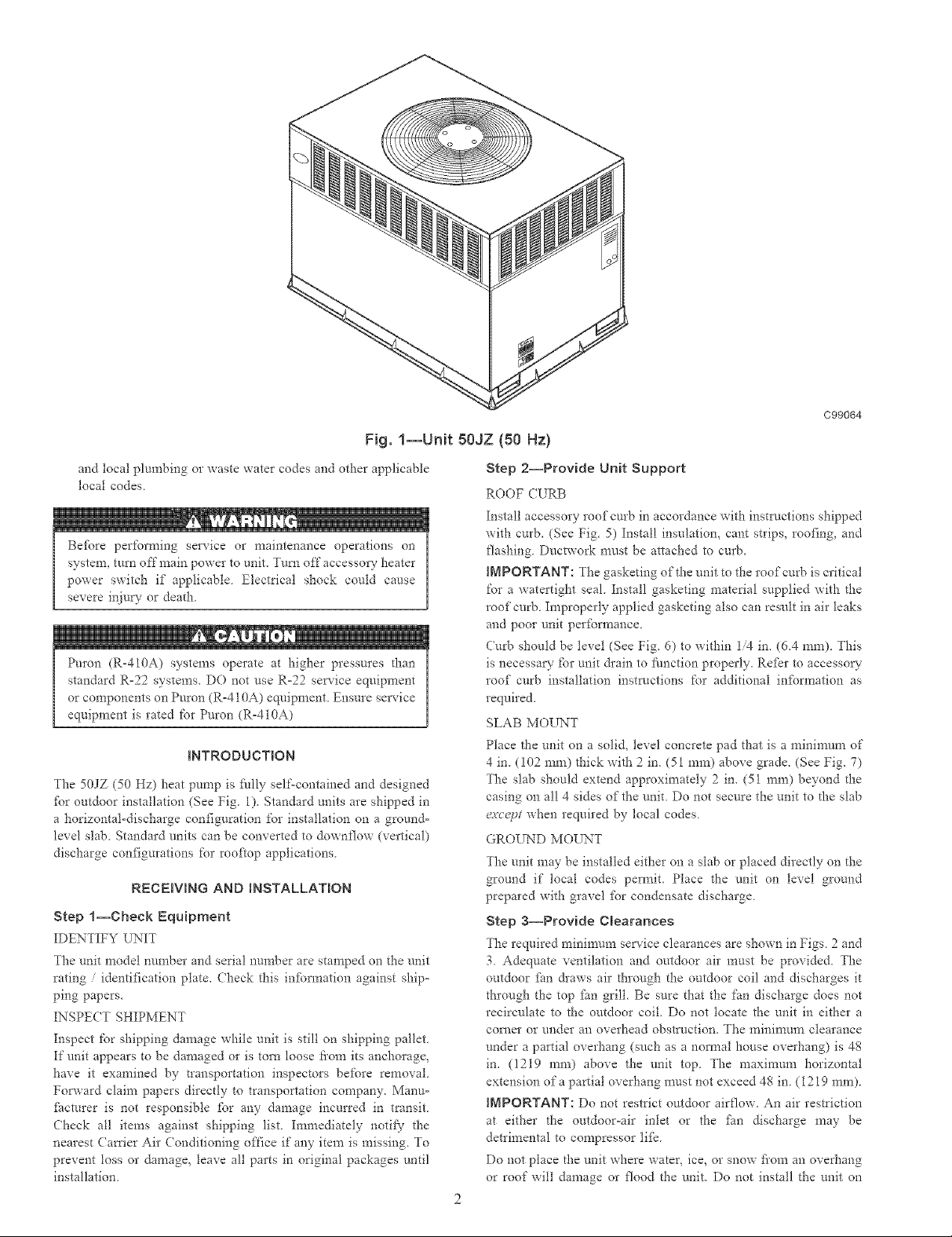
Fig. 1--UNt 50JZ (50 Hz)
and local plumbing or _xaste water codes and other applicable
local codes
Be%re per%rming service or maintenance operations on
system, turn off main power to unit. Turn off accessory heater
power switch if applicable Electrical shock could cause
severe injury or death
Puron (R-410A) systems operate at higher pressures than
standard R=22 systems. DO not use R=22 service equipment
or components on Pnron (R-410A) equipment. Ensure service
equipment is rated for Puron (R-4IOA)
INTRODUCTmON
The 50JZ (50 Hz) heat pump is fhlly selfocontained and designed
fbr otttdoor installation (See Fig. 1) Standard units are shipped in
a horizontal-discharge configuration for installation on a ground=
level slab Standard units can be converted to downflow (vertical)
discharge configurations for rooftop applications
RECEIVING AND INSTALLATION
Step 1--Check Equipment
IDENTIFY UNIT
The unit model number and serial nm'nher are stamped on the unit
rating identification plate. Check this infbrmafion against ship=
ping papers.
INSPECT SHIPMENT
Inspect tbr shipping damage while unit is still on shipping pallet
If unit appears to be damaged or is torn loose ti'om its anchorage,
have it examined by transportation inspectors be%re removal.
Fopxard claim papers directly to transportation company. Manu=
fitcmrer is not responsible fbr any damage incurred in transit.
Check all items against shipping list. Immediately notify the
nearest ( mTier Air Conditioning once if any item is missing. To
prevent toss or damage, leave all parts in original packages until
installation.
C99064
Step 2--Provide Unit Support
ROOF ([RB
Install accessory roof curb in accordance with instrt/cfions shipped
with curb. (See Fig. 5) Install insulation, cant strips, roofing, and
flashing Ductwork must be attached to cuIS.
INPORTANT: The gasketing of the nnit to the roof cm:b is critical
for a watertight seal Install gasketing material supplied with the
roof curb Improperly applied gasketing also can result in air leaks
and poor unit perfbrmance
Curb should be level (See Fig. 6) to within 1/4 in. (6.4 ram). This
is necessa_" t'or unit &ain to fimction properly. Refkr to accessow-
roof curh installation instructions for additional infbrmation as
required.
SLAB MOUNT
Place the unit on a solid, level concrete pad that is a minimum of
4 in. (102 ram) thick with 2 in. (51 ram) above grade. (See Fig. 7)
The slab should extend approximately 2 in. (51 ram) beyond the
casing on all 4 sides of the unit. Do not secure the unit to the slab
except when required by local codes.
GROUND MOUNT
The unit may be installed either on a slab or placed directly on the
ground if local codes permit. Place the unit on level ground
prepared with gravel fbr condensate discharge.
Step a--Provide Clearances
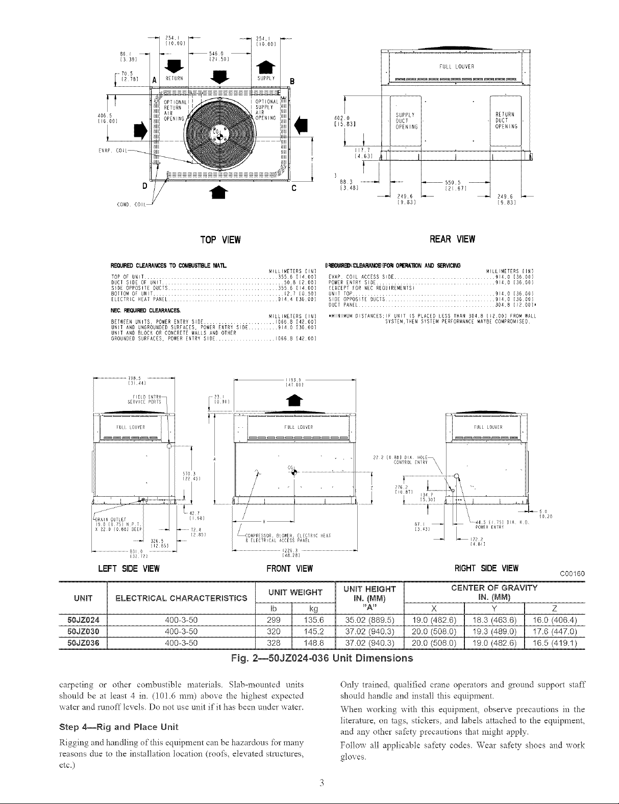
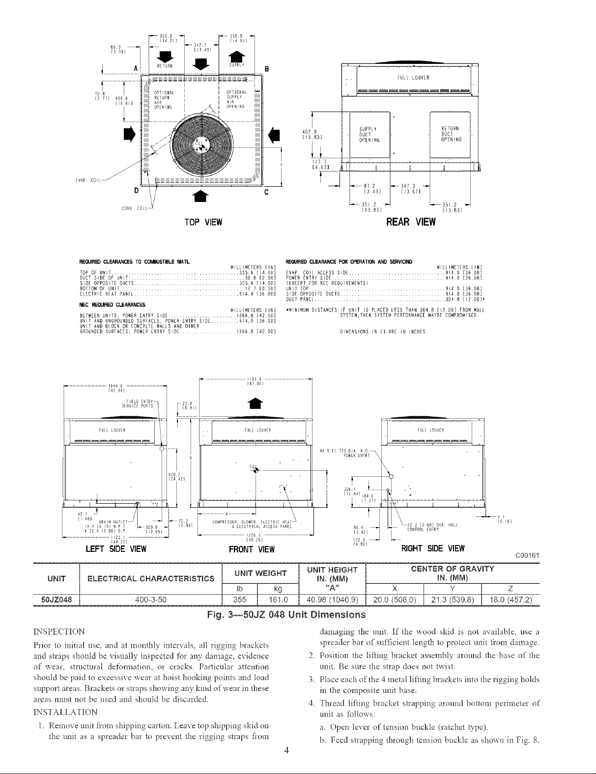
The required minimum service clearances are shown in Figs 2 and
3 Adequate ventilation and outdoor air must be provided. The
outdoor fire &aws air through the outdoor coil and discharges it
through the top fYn grill. Be sure that the fan discharge does not
recirculate to the outdoor coil. Do not locate the unit in either a
corner or under an overhead obstruction. The minimum clearance
under a partial overhang (such as a nom_al house overhang) is 48
in. (1219 ram) above the unit top. The maximum horizontal
extension of a partial overhang must not exceed 48 in. (1219 ram).
IMPORTANT: Do not restrict outdoor airflow. An air restriction
at either the outdoor=air inlet or the fire discharge may be
detrimental to compressor tifk
Do not place the unit where water, ice, or snow fi'om an overhang
or roof will damage or flood the unit Do not install the unit on
il..........................r LLLo vE l
Tt
406 5
[_6 60]
EVAP l
TOP VIEW
RE'G_RED CLEARANCES TO COMBtIS_BLE MA'n-
TOP OF UNIT ............................................. 3556 [1400]
DUCT SiDE OF RNIT ......................................... 508 {200]
SIDE OPPOSITE DUCTS ..................................... 3556 [14001
BOTTOM OF UNIT ............................................ 127 {0501
ELECTRIC HEAT PANEL ..................................... 9144 [36001
NED. REQUIRED CLEARANCE&
BETWEEN UNITS, POWER ENTRY SIDE ........................ 10668 [4200]
UNiT AND UNGROUNDED SORTADES, POWER ENTRY SIDE .......... 914¸0 [3600]
UNiT AND BLOCN OR CONCREIE WAILS AND OTHER
GROUNDED SURFACES, POWER ENTRY SIDE .................. 1066¸8 [4200]
{31 44/
_IEIR _NTRY
S£RV_CE PORTS
• 11939
loiH
i" -n
MiLLiMETERS [iN]
MIllIMETERS [IN]
[47 O0
4020
[_583]
SUPP{ Y
DUCT
OPENING
i ;
177
Y
{463]
}
885 ....................................
[3¸48}
D_EeN_LEARANG_TO_ ORERM_'_ON AND SERVICINB
EVAP COIL ACCESS SIDE .................................. 914¸0 [36¸001
POWER ENTRY Si0E ........................................ 914¸0 [36.001
(EXCEPT HOH NEE REOUIREWENTS)
UNIT TOP ................................................ 914¸0 [36¸001
SiDE OPPOSITE 00GTS ..................................... 914¸0 [36¸001
DUCT PANEL .............................................. 304¸8 [12061,
*NININON DISTANCES:IF UNiT IS P{ACED LESS THAN 3048 [JRO0] FRON WALL
SYSTEM,IHEN SYSIEN PER;ORNANCE NAY_E COMPROMISER
24£¸6
I983]
I
_5505
REAR VIEW
t I
[2167]
NILLIMETERS [IN1
RETURN
DUCT
OPENING
[9831
A
i I i _
[168]
[2851
_12851
13212]
LCO_PRESSOR, BLOWER, EtECJRIC HEAY
& ELECTRICAL ACCESS PANgL
................................................._2263 ..........................................................
[48 281
LEFT SIDE VIEW FRONTVIEW RIGHT SIDE VIEW
UNiT
80JZ024
80JZO30
50JZ036
ELECTRICAL CHARACTERiSTiCS
400-3-50
400-3-50
400-3-50
UNIT WE_GHT
Ib kg
299 135.6
320 145.2
328 148.8
Fig. 2--50JZ024-036 Unit Dimensions
carpeting or other combustible materials Slab=mounted malts
should be at least 4 in. (101.6 ram) abo_e the highest expected
v, ater and runoff levels Do not use unit if it has been under water.
Step 4--Rig and Place Unit
Rigging and handling of this equipment can be hazardmEs %r many
reasons due to the installation location (roo£q, elevated structures,
etc,)
-}..LO..i
..62 l ' _
.......i [IO 87} 13_ / ........ ,
7 4 _-- 445 { 75] DIA K 0
{4 81]
C00160
UNIT HEBGHT
IN.(MM)
"A"
35.02 (889.5)
37.02 (940.3)
37.02 (940.3)
Only trained, qnalified crane operators and ground support staff
should handle and install this equipment,
When working with this equipment, obseza'e precautions in tlae
literature, on tags, stickers, and labels attached to the equipment,
and any other safety precautions that might apply.
Follow all applicable safety codes. Wear safety shoes and work
gloves.
19.0 (482.6) 18.3 (463.6) 16.0 (406.4)
20.0 (508.0) 19.3 (489.0) 17.6 (447.0)
20.0 (508.0) 19.0 (462.6) 16.5 (419.1)
CENTER OF GRAVITY
IN.(MM)
X Y Z
. FULL LOUV[R
J
I
EVAP c011
° /
CO_l) COil
TOP VIEW
REQ4JIRB_CLEARANCES TO COr_BIJSTIBLE MAll..
lOP OF UNIT ........................................... 3556 [1400]
DUCT SIDE OF UNIT ......................................... 508 [?OO]
SIDE OPPOSITE DUCTS ..................................... 355¸6 [14OO]
_OTTOM OP UNIT ............................................ 127 [OSO]
ELECTRIC NEAT PANEl..................... 9}4¸4 {36 00}
NEC. REel]RED CLEARANCES.
BETWEEN UNITS, POWER ENTRY SIDE ........................ 10668 [420DI
UNIT AND UNGROUNDED SURFACES, POWER ENTRY SIDE .......... 9}4¸0 [3DOO]
UNIT AND BLOCK OR CONCRETE WALES AND OTHER
GROUNDED SURFACES, POWER ENTRY S{DE ...... {066 8 {42 00]
.............................................I090_ ............................................
[4294]
FULL _OUV#R
SERVICE PORTS
F_E_D [NTRY_
....................................... I
MILLIMETERS IIN]
MILL!ME]ENS [IN]
................................................ 11_39 ...................................................
[47 00)
4020
[5831
t
117 7
SUPPLY RETURN
DUCT DUCT
OPEN NG OPEN NG
,il'
l i J
_81,2 _3AYS
1S,431 IIS 6YI
_351 ? _ _331,2
I13_DSI I13_831
REAR VIEW
REQUIRED CLEARANCE FOR OPERATION AND SB_IVICING
EVAP CO{L ACCESS SIDE ................................. 914¸0 [36¸001
POWER ENTRY SIDE ........................................ 914D [36¸001
{EXCEPT FOR NED REQUIREMENTS}
UNIT TOP ................................................ 9140 [36¸00I
SIDE OPPOSITE DUCTS ............................... 914¸0 [36¸001
DUCT PANZL ............................. 304 8 {I?OO}_
_MINIMNM D!STANDES:IF UNIT IS PLACED LESS THAN 3048 [!DOO] FROM WALL
SYSTEM,THEN SYSTEM PERFORMANCE MAYDE COMPROMISED
DIMENSIONS IN {} ARE IN INCHES
MILLIMETERS [IN}
FULL LOUVZR
620 2
'14.'i
[48 28
FRONT VIEW
UNIT
50JZ048
ELECTRICAL CHARACTERiSTiCS IN. (Mivl}
400-%50 355 161.0 40.98 (1040.9)
[NSPE(TION
Prior to initial use, and at monthly intervals, all rigging brackets
and straps should be visually inspected for any damage, evidence
of wear, structural deformatiom or cracks. Pa_1icular attention
should be paid to excessive wear at hoist hooking points and load
support areas. Brackets or straps showing any kind of wear in these
areas must not be used and should be discarded.
[NSTALLATION
1, Remove unit li'ona shipping carton. Leave top shipping skid on
the unit as a spreader bar to prevent the rigging straps flora
UNIT WEIGHT UNIT HEIGHT
tb kg "A"
Fig. 3--50JZ 048 Unit Dimensions
44 5 [{ 75101A K O_
POWER _NTRY
.............. 4
0 161
'2;'- L_
[4 81 RIGHT SIDE VIEW
CENTER OF GRAVITY
IN. {MN)
X Y Z
200 (508.0) 21.3 (539.8) 18.0 (457.2)
damaging the unit. If the wood skid is not available, use a
spreader bar of sufficient length to protect unit fi'orn damage.
2,
Position the ti_ing bracket assembly around the base of the
unit. Be sure the strap does not twist
3,
Place each of the 4 metal lifting brackets into the rigging holds
in the composite unit base
4,
Thread lifting bracket strapping around bottom perimeter of
unit as follows:
a Open lever of tension buckle (ratchet type)
b. Feed strapping through tension buckle as shown in Fig 8
C00161
1
Y
4 x 3
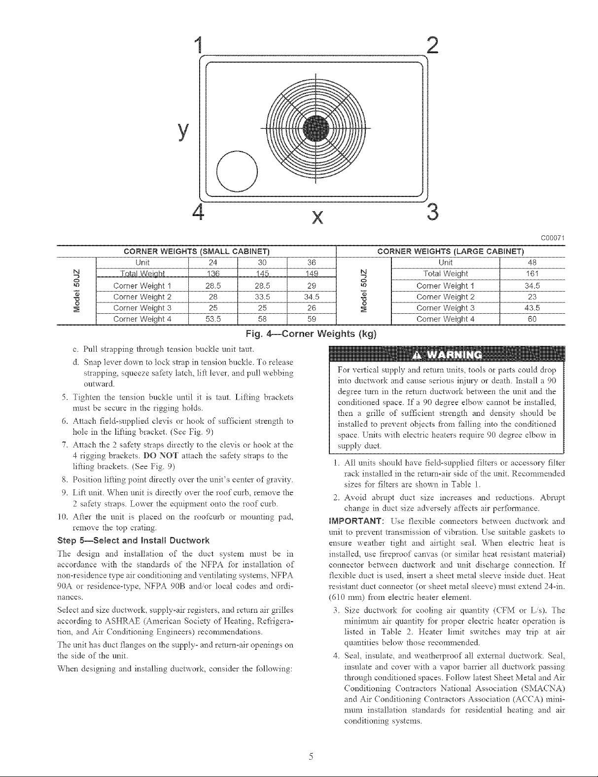
CORNER WEIGHTS (SMALL CABRNET)
N
O
o
c Pull strapping through tension buckle unit taut.
d. Snap lever down to lock strap in tension buckle. To release
strapping, squeeze safkty latch, lift lever, and pull webbing
outward
5. Tighten the tension buckle until it is taut Lifting brackets
n-rest be secure in the rigging holds
6. Attach field-supplied clevis or hook of sufficient strength to
hole in the lifting bracket. (See Fig 9)
7. Attach the 2 safkty straps directly to the clevis or hook at the
4 rigging brackets. DO NOT attach the safkty straps to the
lifting brackets. (See Fig 9)
8. Position lifting point directly over the unit's center of gravity
9. Lift unit When unit is directly over the roof curb, remove the
2 safBty straps. Lower the equipment onto d3e roof curb
10. After the unit is placed on the roofcurb or mounting pad,
remove [he top crating.
Step 5--Select and hstaH Duetwork
The design and installation of the duct system must be in
accoIdance with [he standards of [he NFPA for installation of
non-residence type air conditioning and ventilating systems, NFPA
90A or residence-Vpe, NFPA 90B an_or local codes and ordi-
nances
Select and size ductworl% supply_air registers, and return air grilles
according to ASHRAE (American Society of Heating, Ret'rigerao
tion, and Air Conditioning Engineers) recommendations.
The unit has duct flanges on the suppty_ and returnoair openings on
the side of [he unit.
When designing and installing ductwork, consider the _bllowing:
Unit
Total Weiqh_
Corner Weight 1
Corner Weight 2
Corner Weight 3
Corner Weight 4
24 30
18_ 14_
28.5 28.5
28 33.5
25 25
53.5 58
Fig. 4_Comer Weights (kg)
CORNER WEIGHTS (LARGE CABINET)
36
149
29
34.5
26
59
IMPORTANT: Use flexible connectors between ductwork and
unit to prevent transmission of vibration. Use suitable gaskets to
ensure weather tight and airtight seal. When electric heat is
installed, use fireproof canvas (or similar heat resistant material)
connector between ductwork and unit discharge connection. If
flexible duct is use& insert a sheet metal sleeve inside duct. Heat
resistant duct connector (or sheet metal sleeve) must extend 24-in.
(610 ram) fi'om electIic heater element.
N
O
o
For vertical supply and return units, tools or parts could &op
into dnctwork and cause serious injury or death Install a 90
degree mrn in the return ductwork between the unit and the
conditioned space. If a 90 degree elbow cannot be installed.
then a grille of sufficient strength and density should be
installed to prevent objects fiom fi_lling into the conditioned
space Units with electric heaters require 90 degree elbow in
supply duct
1 All units should have field-supplied filters or accessory filter
rack installed in the return-air side of the unit. Recommended
sizes _br filters are shown in Table 1
2. Avoid abrupt duct size increases and reductions. Abrupt
change in duct size adversely affects air per_bm_ance.
3. Size ductwork _br cooling air quantity (CFM or L/s). The
minimum air quantity fbr proper electric heater operation is
listed in Table 2. Heater limit switches may trip at air
quantities below those recommended.
4. Seal, insulate, and weatherproof all external ductwork. Seal,
insulate and cover with a vapor battier all ductwork passing
through conditioned spaces. Follow latest Sheet Metal and Air
(onditioning Conkactors National Association (SMACNA)
and Air ( onditioning Contractors Association (AC(A) mini-
mum installation standards for residential heating and air
conditioning systems.
Unit
Total Weight
Corner Weight 1
Corner Weight 2
Corner Weight 3
Corner Weight 4
C00071
48
161
34.5
23
43.5
60
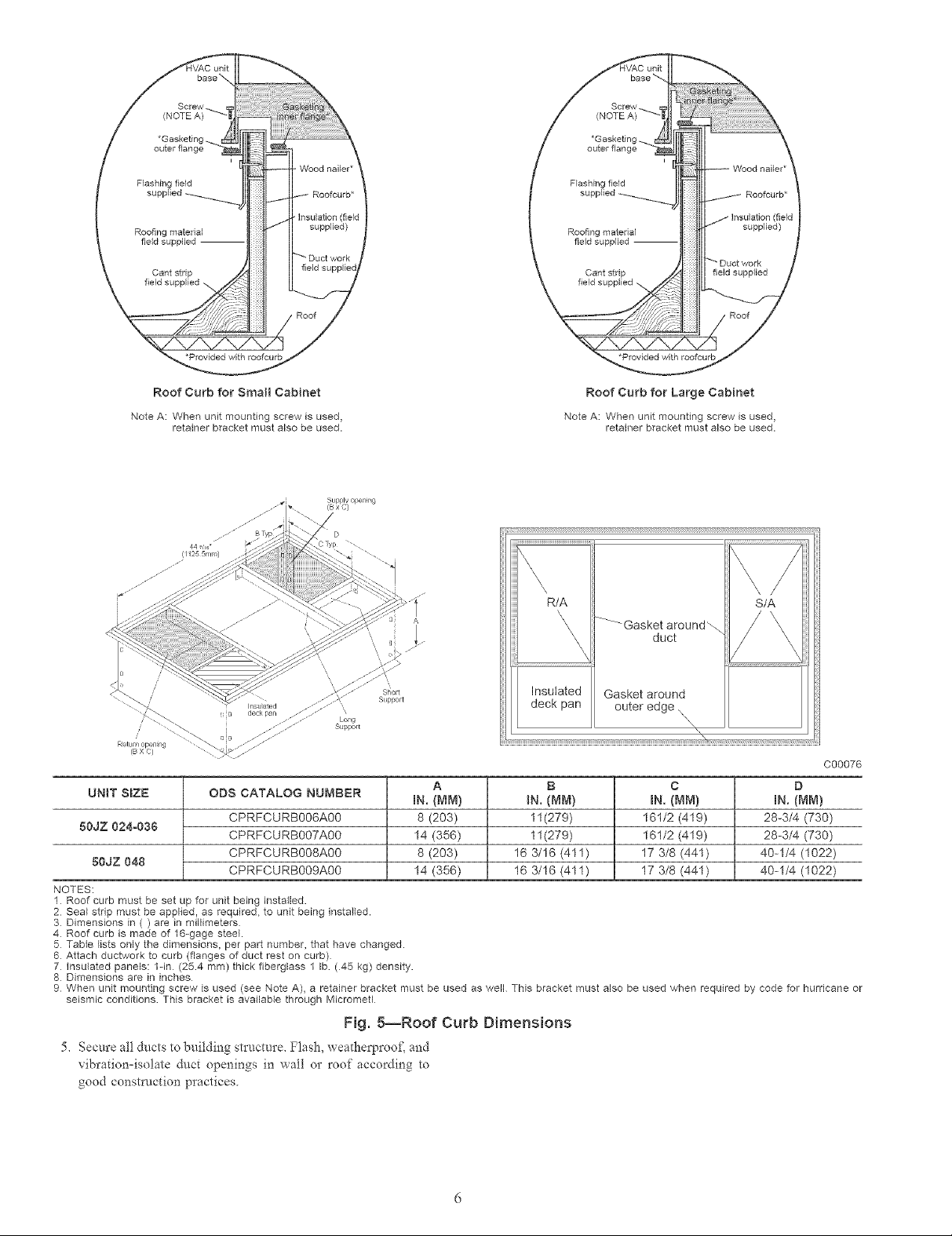
Roof Curb for Smart Cabinet
Note A: When unit mounting screw is used,
retainer bracket must also be used.
01255mm)
Roof Curb for Large Cabinet
Note A: When unit mounting screw is used,
retainer bracket must also be used.
\
R/A
A
_Gasket around_
\
\
\
\
duct
S/A
/2
s ipport
Loug
Support
Retur iopen ng
(B X C)
UNIT SBZE ODS CATALOG NUMB_::R
50JZ 024-036
80dZ 048
NOTES:
1 Roof curb must be set up for unit being instalbd.
2 Seal strip must be applied, as required, to unit being installed.
3 Dimensions in ( ) are in milfimeters
4 Roof curb is made of 16-gage steel.
5 Table lists only the dimensions, per part number, that have changed.
6 Attach ductwork to curb (flanges of duct rest on curb)
7 insulated panels: ldn (254 mm) thick fiberglass 1 Ib (45 kg) density.
8 Dimensions are in inches
9 When unit mounting screw is used (see Note A), a retainer bracket must be used as well This bracket must also be used when required by code for hurricane or
seismic conditions This bracket is available through Micrometl
CPRFCURB006A00 8 (203) 11(279) 161/2 (419) 26-3/4 (730)
CPRFCURB007A00 14 (356) 11(279) 161/2 (419) 28-3/4 (730)
CPRFCURB008A00 8 (203) 16 3/16 (411) 17 3/8 (441) 40-1/4 (1022)
CPRFCURB009A00 14 (356) 16 3/16 (411) 17 3/8 (441) 40-1/4 (1022)
A B C D
IN. {MM) IN. (MM) IN. {MN} IN. (NM)
Insulated
deck pan
Gasket around
outer edge \
\"\4
'\
C00076
Fig. 5--Roof Curb Dimensions
5, Secure ai! ducts to building structure, Flash, _ eatherproof, and
_ibration=isolate duct openings in _xall or roof according to
good construction practices
3
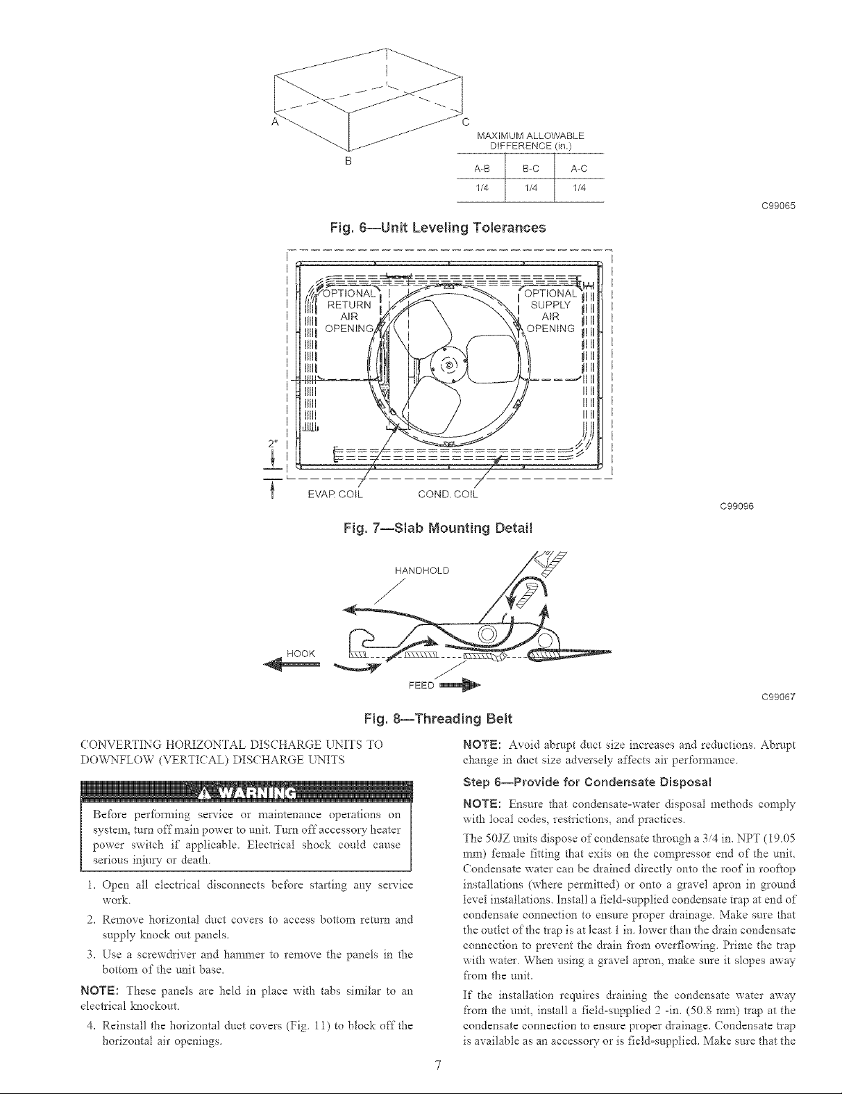
MAXIMUM ALLOWABLE
DIFFERENCE (in.)
A-B B-C A-C
1/4 1/4 1/4
C99065
Fig. 6--UnBt Leveling ToMrances
Illll
Itlll
Illll
I1111
It111
It111
2 _r
mL
EVAR COIL COND. COIL
C99096
Fig. 7--Slab Mounting Detail
HANDHOLD
/
HOOK
Fig. 8--Threading Be{t
CONVERTING HORIZONTAL DISCHARGE UNITS TO
DOVv%*FLOW(VERTICAL) DISCHARGE LNITS
Before perfc_rming service or maintenance operations on
system, trim off main power to unit. Turn off accessory heater
power switch if applicable. Electrical shock could cause
serious injury or death.
1. Open all electrical disconnects before starting any service
work
2. Remove horizontal duct covers to access bottom remm and
supply knock out panels.
3. Use a screwdriver and hammer to remove the panels in the
bottom of the unit base.
NOTE: These panels are held in place with tabs similar to an
electrical knockout
4. Reinstall the horizontal duct covers (Fig. 11) to block offthe
horizontal air openings.
FEED
C99067
NOTE: Avoid abrupt duct size increases and reductions Abrl/pt
change in duct size adversely affects air performance.
Step 6--Provide for Condensate Disposal
NOTE: Ensure that condensate-water disposal methods comply
with local codes, restrictions, and practices.
The 50JZ units dispose of condensate through a 3/4 in. NPT (I9.05
ram) f_male fitting that exits on the compressor end of d'*e unit.
Condensate water can be drained directly onto the roof in rooflop
installations (where permitted) or onto a gravel apron in ground
level installations. Install a field-supplied condensate trap at end of
condensate connection to ensure proper drainage. Make sure that
the outlet of the trap is at least 1 in. lower than the &ain condensate
connection to prevent the drain fi'om overflowing. Prime the trap
with water. When using a gravel apron, make sure it slopes away
I_'om the unit.
If the installation requires draining the condensate water away
from the unit, install a field-supplied 2 -in. (50.8 ram) trap at the
condensate connection to ensure proper &ainage. Condensate trap
is available as an accessory or is field-supplied. Make sure that the
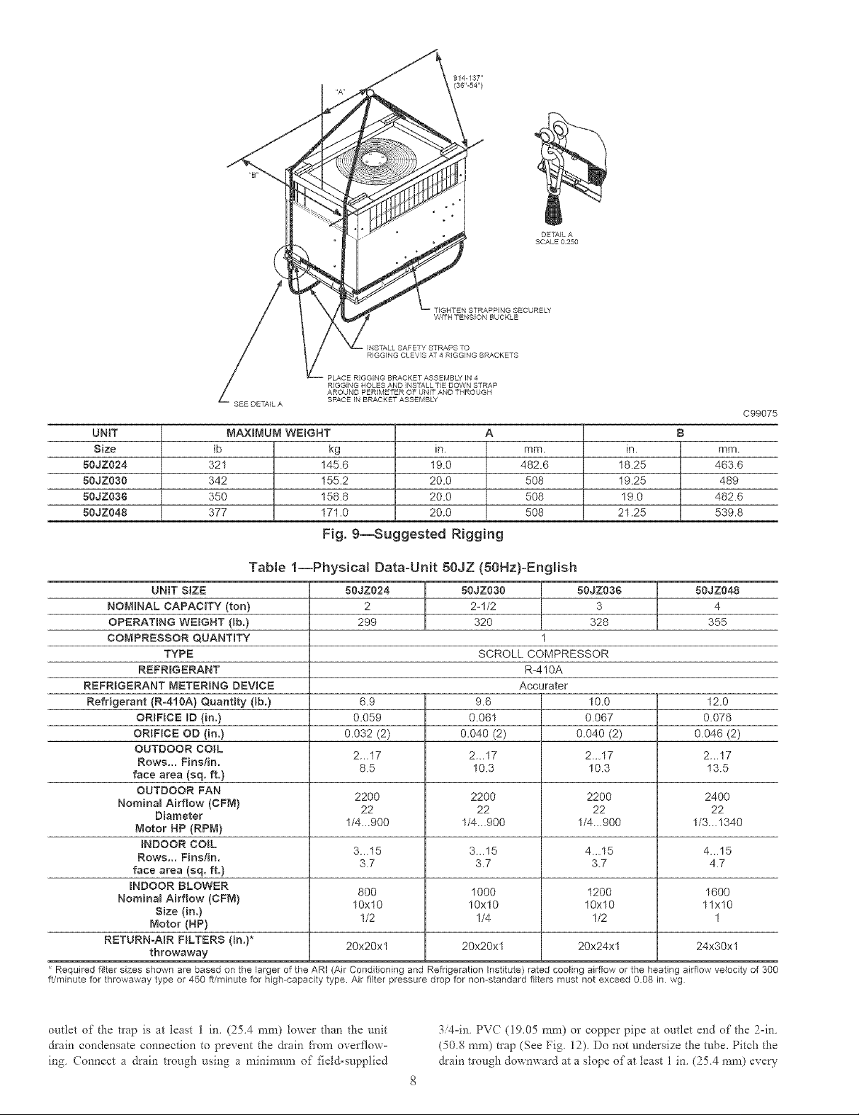
DETAIL A
SCALE 0250
TIGHTEN STRAPPING SECURELY
WITH TENSION BUCKLE
= INSTALL SAFETY STRAPS TO
RIGGING CLEVIS AT 4 RIGGING BRACKETS
PLACE RIGGING BRACKET ASSEMBLY IN 4
RIGGING HOLES AND INSTALL TIE DOWN STRAP
AROUND PERIMETER OF UNIT AND THROUGH
SPACE IN BRACKET ASSEMBLY
in.
19.0
20.0
20.0
20.0
C99075
A
mm.
482.6
5O8
5O8
5O8
in.
18.25
19.25
19.0
21.25
B
mm.
463.6
489
482.6
539.8
UNiT
Size
80JZ024
80JZ0S0
80JZ036
80JZ048
SEE DETAIL A
MAXBMUMWEJGHT
tb kg
321 145.6
342 155.2
350 158.8
377 171.0
Fig. 9--Suggested RiggBng
Table 1--Physicam Data-UnR 50JZ (50Hz}-English
UNIT SIZE
NOMINAL CAPACITY (ton}
OPERATING WEBGHT (lb.)
COMPRESSOR QUANTITY
TYPE
REFRIGERANT
REFRBGERANT METERBNG DEVICE
Refrigerant (R-41OA} Quantity (lb.)
ORIFICE ID (in.}
ORIFICE OD (in.}
OUTDOOR CO_L
Rows... Finslin.
face area (sq. ft.}
OUTDOOR FAN
Nomina_ Airflow (CFM}
Diameter
Motor HP (RPM)
_NDOOR COBL
Rows... Fins/in.
face area (sq. ft.}
mNDOOR BLOWER
Nomina_ Airflow (CFM)
Size (in.)
Motor (HP}
RETURN-AIR HLTERS (in,)*
throwaway
Required filter sizes shown are based on the larger of the ARI (Air Conditioning and Refrigeration Institute) rated cooling airflow or the heating airflow velocity of 300
ft/minute for throwaway type or 450 if/minute for high-capacity type. Air filter pressure drop for non-standard filters must not exceed 0.08 in wg
80JZ024
2
299
50JZ08O 50JZ088
2-1/2 3
320 328
80JZ048
4
355
1
SCROLL COMPRESSOR
R-410A
Accurater
6.9
0.059
0.032 (2)
2...17
8.5
2200
22
1/4...900
3...15
3.7
800
10x10
1/2
9.6
0.061
0.040 (2)
2...17
10.3
2200
22
1_...900
3...15
3.7
1000
10x10
1/4
10.0
0.067
O.040 (2)
2...17
10.3
22OO
22
1/4...900
41..15
3.7
1200
10x10
1/2
12.0
0.078
0.046 (2)
2...17
13.5
2400
22
1/3...1340
4...15
4.7
1600
11x10
1
20x20x1 20x20xl 20x24xl 24x30xl
outlet of the tlap is at least 1 in, (25,4 mnx) lower than the unit
drain condensate connection to prevent the &ain flora overflow°
ing (onnect a drain tlough using a n_inil*num of _ield-supplied
3/4=in PVC (19,05 ram) o1"copper pipe at outlet end of the 2=in
(508 nxm) trap (See Fig 12) Do not undersize the tube, Pitch the
drain t*ough downward at a slope of at 1east 1 in, (254 mnx) eve W
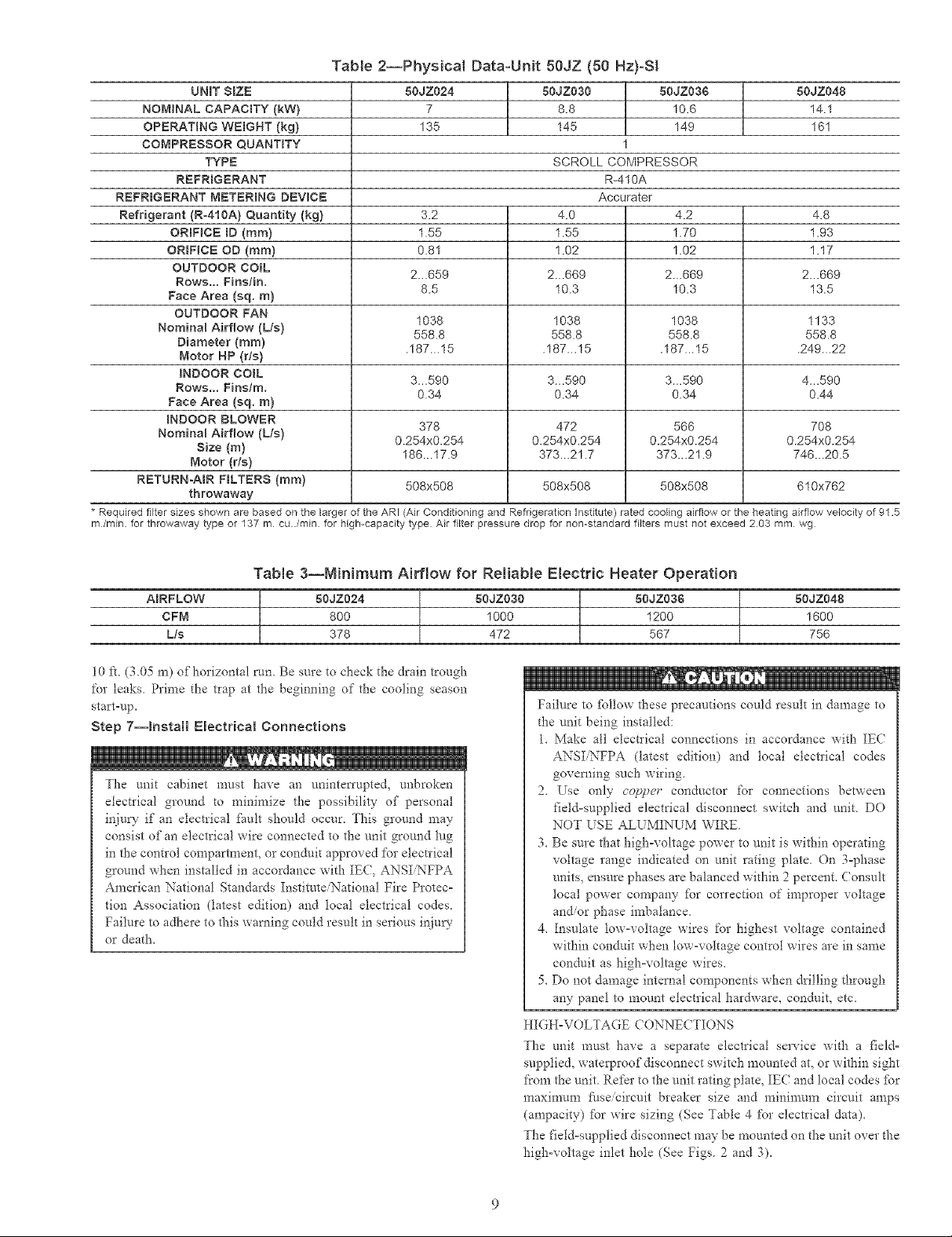
Table 2--PhysicN Data-UNt 50JZ (50 Hz)-SI
UNIT SiZE
NOMINAL CAPACBTY (kW}
OPERATING WEBGNT (kg}
COMPRESSOR QUANTITY
TYPE
REFRBGERANT
REFRIGERANT METERBNG DEVtCE
Refrigerant (R-410A) Quantity (kg)
ORIFICE ID (ram)
ORIFICE OD (ram)
OUTDOOR COiL
Rows.,. Finstin.
Face Area (sq. m)
OUTDOOR FAN
Nomina_ Airflow (L/s)
Diameter (ram)
Motor HP (rls)
iNDOOR COraL
Rows... Finstm.
Face Area (sq. m)
RNDOOR BLOWER
Nominal Airflow (Lls)
Size (m)
Motor (r/s)
RETDRN-ABR FBLTERS (ram)
* Required filter sizes shown are based on the larger of the ARI (Air Conditioning and Refrigeration Institute) rated cooling airflow or the heating airflow velocity of 91.5
m/min, for throwaway type or 137 m cu../min for high-capacity type Air filter pressure drop for non-standard filters must not exceed 203 mm wg
throwaway
50JZ024
7
135
3.2
1.55
0.81
2...659
8.5
1038
556.8
.167...15
3...590
0.34
378
0.254x0.254
186...17.9
508x508
50JZ030 50J2:03$
8.8 10.6
145 149
1
SCROLL COMPRESSOR
R-410A
Accurater
4.0
1.55
1.02
2...669
10.3
1036
558.8
.167...15
3...590
0.34
472
0.254x0.254
373...21.7
508x508
2_.669
558.8
.187...15
3...590
0.254x0.254
373...21.9
508x508
4.2
1.70
1.02
10.3
1038
0.34
566
50JZ048
14.1
161
4.8
1.93
1.17
2...669
13.5
1133
558.8
.249...22
4...590
0.44
7O8
0.254x0.254
746...20.5
610x762
Table 3--MiNmum Airflow for Reliable Electric Heater Operation
ABRFLOW
CFM
L/s
10 ft. (3.05 m) of horizontal run. Be sure to check the drain trough
for leaks Prime tile trap at the beginning of tile cooling season
start=up.
Step 7--Install Electrical Connections
The unit cabinet must have an uninterrupted, unhroken
electrical ground [o minimize the possibility of personal
injury if an electrical _imlt should occur. This ground may
consist of an electrical wire connected to the unit ground lug
in the control compartment, or conduit approved for electrical
ground when installed in accordance with IEC, ANSI NFPA
American National Standards Institute/National Fire Protec-
tion Association (latest edition) and local electrical codes.
Failure to adhere to this warning could result in serious inju_'
or death.
50JZ024 80JZ030 50JZ036
800 1000 1200
378 472 567
50JZ648
1600
756
Failure to %llow these precautions could result in damage to
the unit being installed:
1_ Make all electrical connections in accordance with IEC
ANSINFPA (latest edition) and local electrical codes
governing such wiring.
2_ Use only copper conductor for connections between
field-supplied electrical disconnect switch and unit. DO
NOT USE ALUMINUM WIRE.
3. Be sure that high-voltage power to unit is within operating
voltage range indicated on unit rating plate. On 3-phase
units_ ensure phases are balanced within 2 percent. ( onsult
local power company fbr correction of improper voltage
and/or phase imbalance.
4. Insulate low-voltage wires for highest voltage contained
within conduit when low=voltage control wires are in same
conduit as high-voltage wires.
5. De not dan?age internal components when drilling through
any panel to mount electrical hardware, conduit, etc_
HIGH-VOLTAGE ( ONNECTIONS
The unit must have a separate electrical service with a field-
supplied, waterproof disconnect switch mounted at. or within sight
from the unit. Refer to the unit rating plate, IE( and local codes tbr
maximnm _i/seicircuit breaker size and minin-mm circuit amps
(ampacity) fbr wire sizing (See Table 4 for electrical data).
The field=supplied disconnect may be mounted on the unit over the
high=voltage inlet hole (See Figs. 2 and 3).
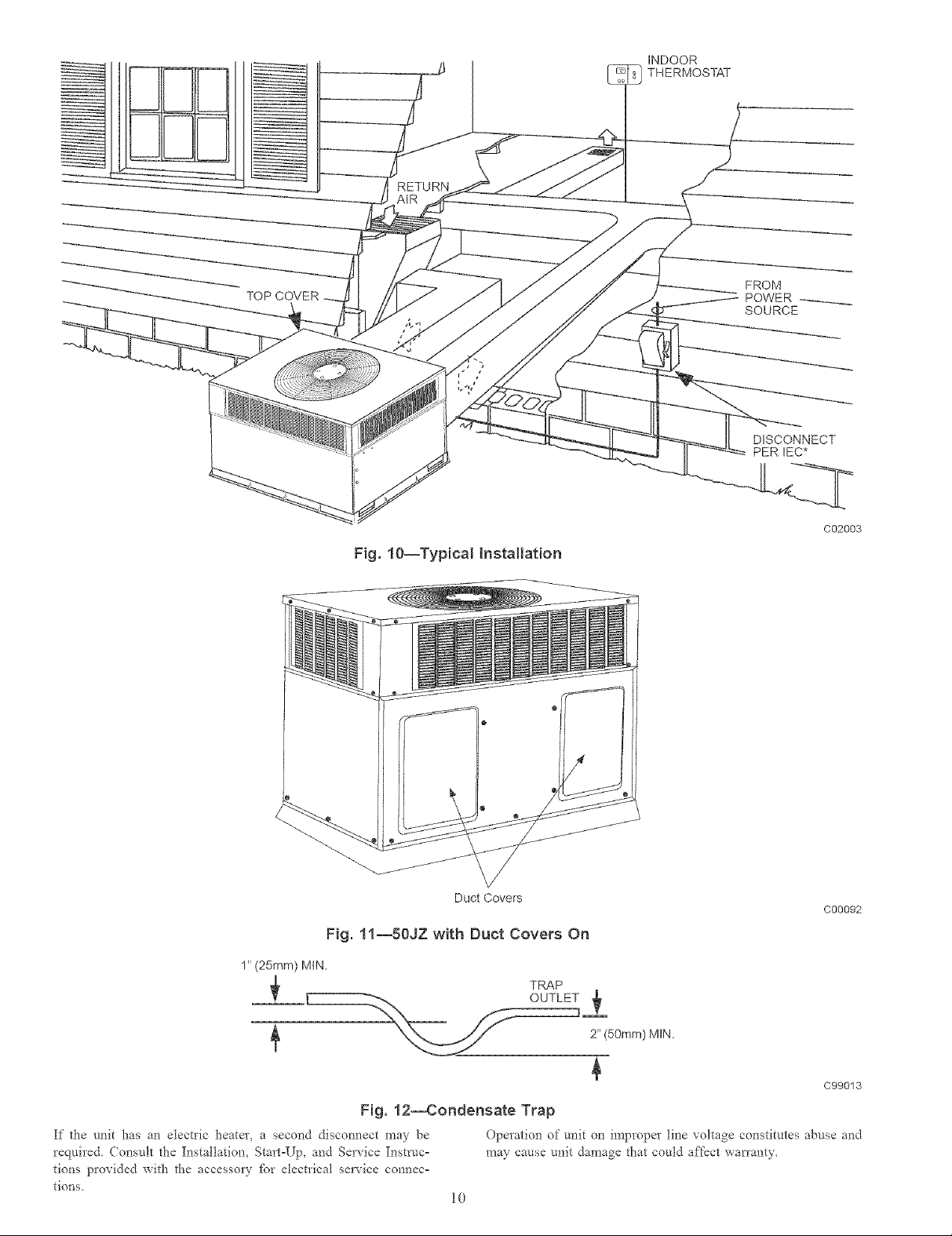
TOP COVER
INDOOR
THERMOSTAT
RETURN
DISCONNECT
PERIEC*
Fig. 10--Typical Installation
Duct Covers
Fig. 11--50JZ with Duct Covers On
C02003
C00092
TRAP
_.,__ 2" (50ram) MIN.
C99013
Fig. 12--Condensate Trap
If the unit has an electric heateL a second discom_ect may be Operation of unit o_1 improper line voltage co_lstitutes abuse and
required. Consult the Installation, Start°Up, and Service Iustruc° may cause unit damage that could affect warranty.
tions provided with the accessory fc_r electrical service connec=
tions.
10
 Loading...