

Carrier 50JX060300, 50JX048300, 50JX030300, 50JS048300, 50JS036300 Installation Guide
...
HEA33NG & COOLING
Visit www.c,_ier.com
50JS, 50JX
Single-Packaged Heat Pump Units
Installation, Start-Up,
and Service Instructions
NOTE: Read the entire instruction manual before starting the
installation.
TABLE OF CONTENTS
SAFETY CONSIDERATIONS ..................................................... t
INTRODUCTION .......................................................................... 2
RECEIVING AND INSTALLATION .......................................... 2
Check Equipment ...................................................................... 2
IDENTIFY UNIT ................................................................ 2
INSPECT SHIPMENT ........................................................ 2
Provide Unit Support ................................................................ 2
ROOF CURB ....................................................................... 2
SLAB MOUNT ................................................................... 2
GROUND MOUNT ............................................................ 2
Provide Clearances .................................................................... 2
Rig and Place Unit .................................................................... 2
INSPECTION ...................................................................... 2
INSTALLATION ................................................................ 2
Select and Install Ductwork ..................................................... 4
CONVERTING HORIZONTAL DISCHARGE UNITS TO
DOWNFLOW (VERTICAL) DISCHARGE UNITS ......... 5
Provide for Condensate Disposal ............................................. 6
Install Electrical Connections ................................................... 7
HIGH-VOLTAGE CONNECTIONS ................................ 10
ROUTING POWER LEADS INTO UNIT ...................... 10
CONNECTING GROUND LEAD TO GROUND LUG. 10
ROUTING CONTROL POWER WIRES (24-V) ............ 13
SPECIAL PROCEDURES FOR 208-V OPERATION ...15
PRE-START-UP .......................................................................... 17
START-UP ................................................................................... 17
Check for Refrigerant Leaks .................................................. 17
Start-Up Adjustments .............................................................. 17
CHECKING COOLING AND HEATING
CONTROL OPERATION ................................................. 17
CHECKING AND ADJUSTING REFRIGERANT
CHARGE ........................................................................... 18
REFRIGERANT CHARGE .............................................. 18
NO CHARGE .................................................................... 18
LOW CHARGE COOLING ............................................. 19
TO USE COOLING CHARGING CHARTS .................. 19
INDOOR AIRFLOW AND AIRFLOW ADJUST-
MENTS .............................................................................. 19
MAINTENANCE ......................................................................... 20
Air Filter .................................................................................. 21
Indoor blower and motor ........................................................ 21
OUTDOOR COIL, INDOOR COIL, AND
CONDENSATE DRAIN PAN ............................................... 22
Outdoor fan ............................................................................. 23
Electrical controls and wiring ................................................ 23
Reliigerant circuit ................................................................... 24
Indoor airflow ......................................................................... 25
Metering device ...................................................................... 25
Liquid line strainers ................................................................ 25
High Flow Valves ................................................................... 25
Time-delay relay ..................................................................... 25
Loss of charge switch ............................................................. 25
Check defrost thermostat ........................................................ 25
Defrost Thermostat ................................................................. 25
TROUBLESHOOTING ............................................................... 25
START-UP CHECKLIST ............................................................ 25
NOTE TO INSTALLER -- READ THESE INSTRUCTIONS
CAREFULLY AND COMPLETELY before installing this unit.
Also. make sure the Owner's Manual and Service Instructions are
left with the unit after installation.
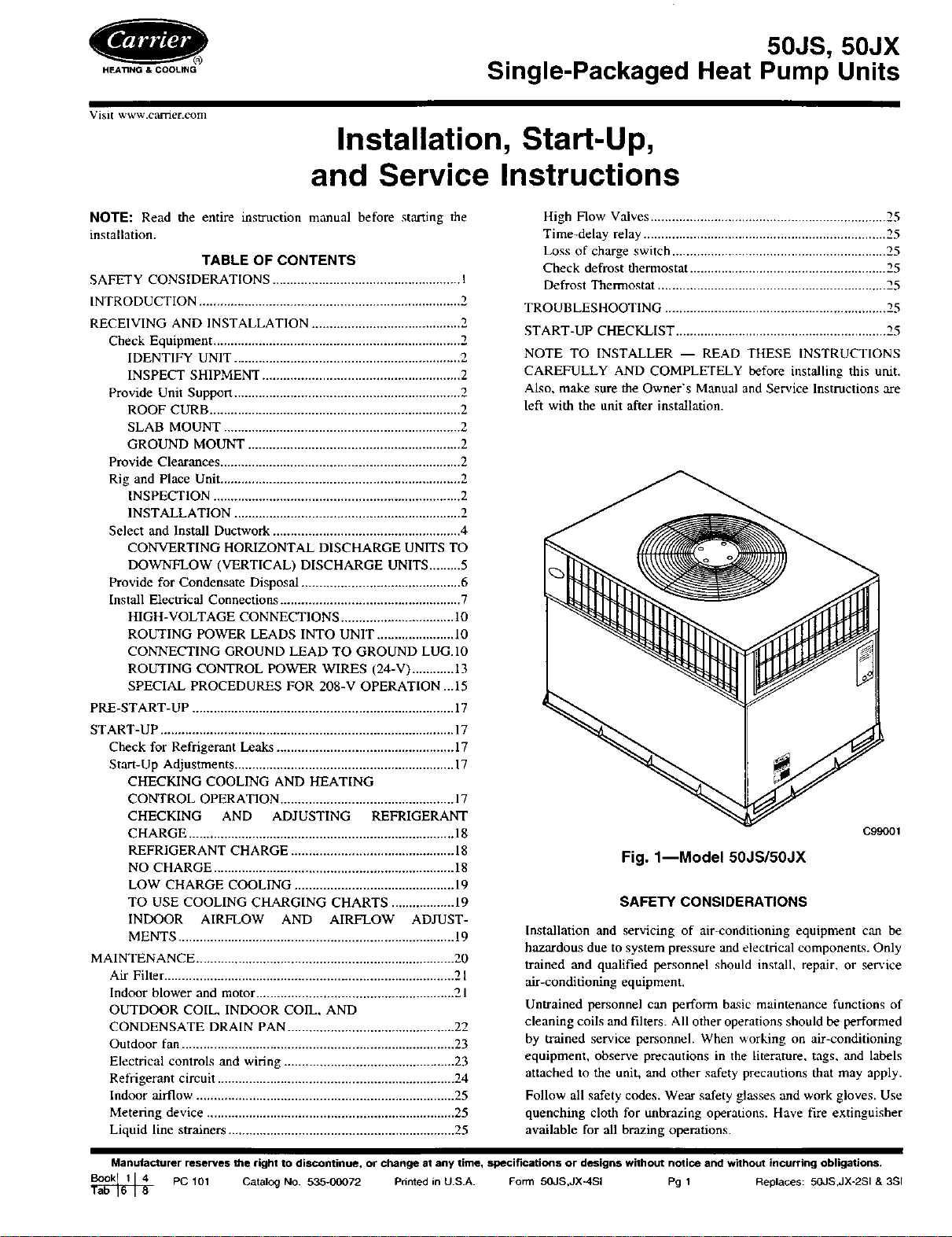
C99001
Fig. 1--Model 50JS/50JX
SAFETY CONSIDERATIONS
Installation and servicing of air-conditioning equipment can be
hazardous due to system pressure and electrical components. Only
trained and qualified personnel should install, repair, or service
air-conditioning equipment.
Untrained personnel can perform ba.qic maintenance functions of
cleaning coils and filters. All other operations should be performed
by trained service personnel. When working on air-conditioning
equipment, observe precautions in the literature, tags, and labels
attached to the unit, and other safety precautions that may apply.
Follow all safety codes. Wear safety glasses and work gloves. Use
quenching cloth for unbrazing operations. Have fire extinguisher
available for all brazing operations.
Manufacturer reserves the right to discontinue, or change at any time, specifications or designs without notice and without incurring obligations.
PC 101 CatalOg No. 535-00072 Printed in U.S.A. Form 50JS,JX-4SI Pg 1 Replaces: 50JS,JX-2SI & 3SI
Improper installation, adjustment, alteration, service, mainte-
nonce, or use can cause explosion, fire. electric shock, or
other occurrences, which could cause serious injury or death
or damage your property. Consult a qualified installer or
service agency for information or assistance. The qualified
installer or agency must use only factory-authorized kits or
accessories when modifying this product.
Recognize safety information. This is the safety-alert symbol/_.
When you see this symbol on the product or in instructions or
manuals, be alert to the potential for personal injury.
Understand the signal words -- DANGER, WARNING, CAU
TION, and NOTE. Danger identifies the most serious hazards,
which will result in severe personal injury or death. Warning
indicates a condition that could cause serious personal injury, or
death. Caution is used to identify unsafe practices, which would
result in minor personal injury or product and property damage.
NOTE is used to highlight suggestions which will result in
enhanced installation, reliability, or operation.
1. The power supply (volts, phase, and hertz) must correspond to
that specified on unit rating plate.
2. The electrical supply provided by the utility must be sufficient
to handle load imposed by this unit.
3. This installation must confortu with local building codes and
with NEC (National Electrical Code). Refer to provincial and
local plumbing or w,'t_te water codes and other applicable local
codes.
Before performing service or maintenance operations on
system, turn off main power to unit. Turn off accessory heater
power switch if applicable. Electrical shock could cause
severe injury or death.
INTRODUCTION
The 50JS and 50JX heat pumps are fully self-contained and
designed for outdoor installation (See Fig. 1). Standard units are
shipped in a horizontal-discharge configuration for installation on
a ground-level slab. Units can be converted to downflow /vertical)
discharge configurations for rooftop applications.
RECEIVING AND INSTALLATION
Step 1---Check Equipment
IDENTIFY UNIT
The unit model number and serial number are stamped on the unit
identification plate. Check this information against shipping pa-
pers.
INSPECT SHIPMENT
Inspect for shipping damage while unit is still on shipping pallet.
If unit appears to be damaged or is torn loose from its anchorage,
have it examined by transportation inspectors before removal.
Forward claim papers directly to transportation company. Manu
facturer is not responsible for any damage incurred in transit.
Check all items against shipping list. Immediately notify the
nearest Carrier Air Conditioning office if any item is missing. To
prevent loss or damage, leave all parts in original packages until
installation.
Step 2--Provide Unit Support
ROOF CURB
Install accessory, roof curb in accordance with instructions shipped
with curb (See Fig. 5). Install insulatiom cant strips, roofing, and
fln_thing. Ductwork must be attached to curb.
IMPORTANT: The gasketing of the unit to the roof curb is critical
for a watertight seal. Install gasketing material supplied with the
roof curb. Improperly applied gasketing also can result in air leaks
and poor unit performance.
Curb should be level to within 1/4 in. (See Fig. 61. This is
necessary for unit drain to function properly. Refer to accessory
roof curb installation instructions for additional information as
required.
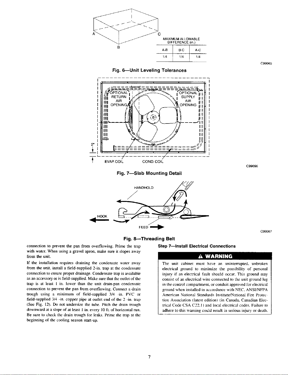
SLAB MOUNT
Place the unit on a solid, level concrete pad that is a minimum of
4 in. thick with 2 in. above grade ISee Fig. 71. The slab should
extend approximately 2 in. beyond the casing on all 4 sides of the
unit. Do not secure the unit to the slab except when required by
local codes.
GROUND MOUNT
The unit may be installed either on a slab or placed directly on the
ground if local codes permit. Place the unit on level ground
prepared with gravel for condensate discharge.
Step 3---Provide Clearances
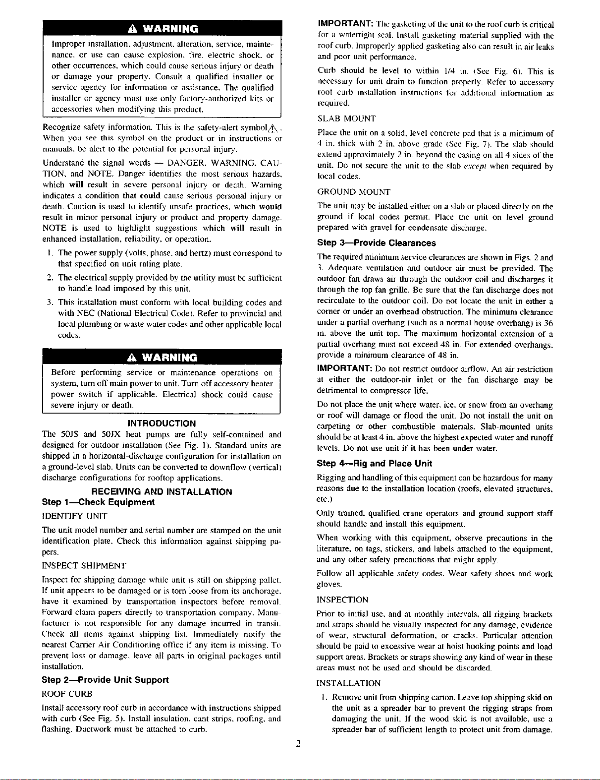
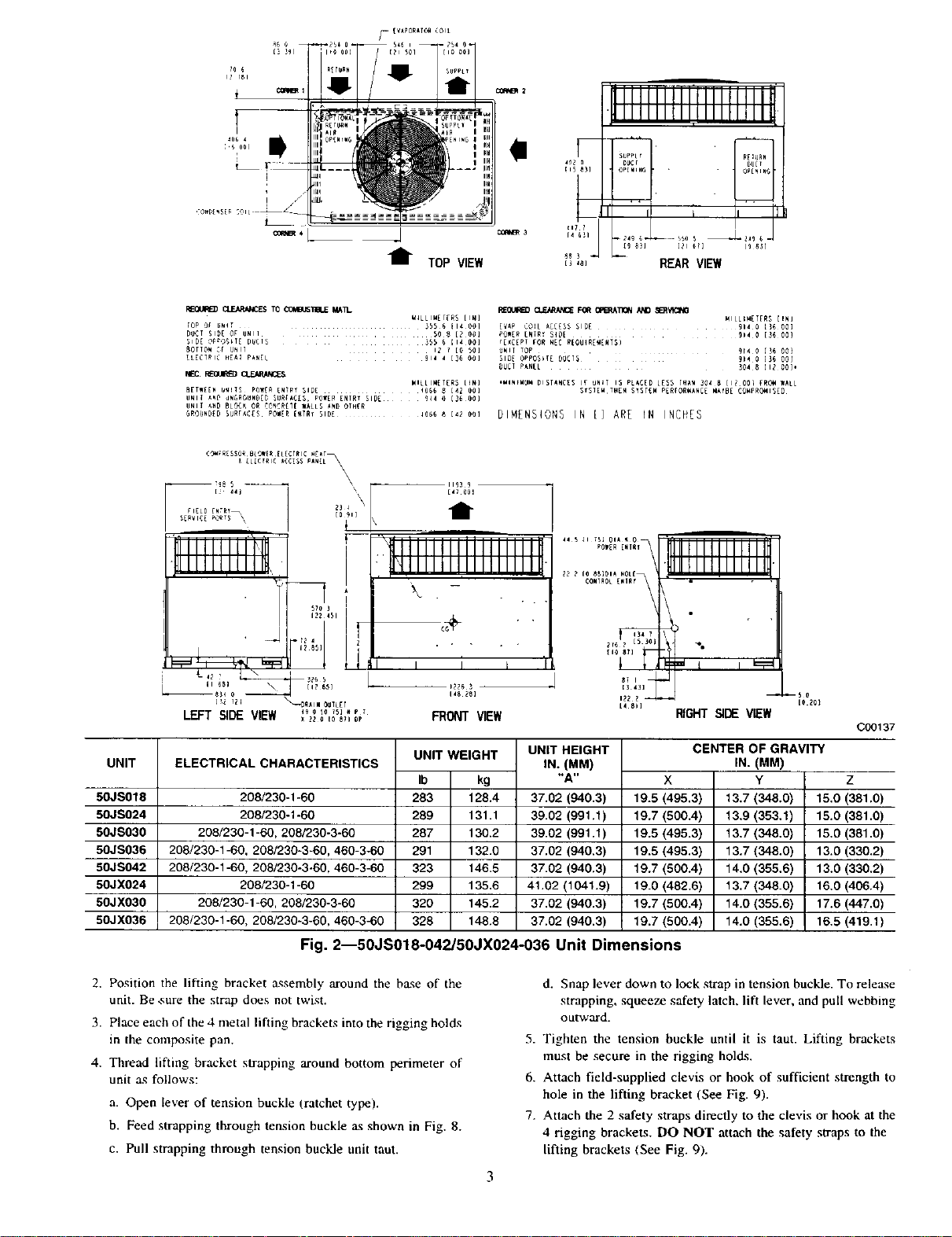
The required minimum service clearances are shown in Figs. 2 and
3. Adequate ventilation and outdoor air must be provided. The
outdoor fan draws air through the outdoor coil and discharges it
through the top fan grille. Be sure that the fan discharge does not
recirculate to the outdoor coil. Do not locate the unit in either a
corner or under an overhead obstruction. The minimum clearance
under a partial overhang (such as a normal house overhang) is 36
in. above the unit top. The maximum horizontal extension of a
partial overhang must not exceed 48 in. For extended overhangs,
provide a minimum clearance of 48 in.
IMPORTANT: Do not restrict outdoor airflow. An air restriction
at either the outdoor-air inlet or the fan discharge may be
detrimental to compressor life.
Do not place the unit where water, ice, or snow from an overhang
or roof will damage or flood the unit. Do not install the unit on
carpeting or other combustible materials. Slab-mounted units
should be at least 4 in. above the highest expected water and runoff
levels. Do not use unit if it has been under water.
Step 4--Rig and Place Unit
Rigging and handling of this equipment can be hazardous for many
reasons due to the installation location (roofs, elevated structures,
etc.)
Only trained, qualified crane operators and ground support staff
should handle and install this equipment.
When working with this equipment, observe precautions in the
literature, on tags, stickers, and labels attached to the equipment,
and any other safety precautions that might apply.
Follow all applicable safety codes. Wear safety shoes and work
gloves.
INSPECTION
Prior to initial use, and at monthly intervals, all rigging brackets
and straps should be visually inspected for any damage, evidence
of wear, structural deformation, or cracks. Particular attention
should be paid to excessive wear at hoist hooking points and load
support arexg. Brackets or straps showing any kind of wear in these
arezts must not be used and should be discarded.
INSTALLATION
1. Remove unit from shipping carton. Leave top shipping skid on
the unit as a spreader bar to prevent the rigging straps from
damaging the unit. If the wood skid is not available, use a
spreader bar of sufficient length to protect unit from damage.
2
/-. [VAP0_AT_ C01t
"l TOP VIEW
UNIT
50JS018
50JS024
5OJSO30
50JS036
50JS042
50JX024
5OJXO30
50JX036
REOt,qRE3 _/JE,_*_CES TO _TIm.E MAIl_ I_OUIRED CLE/g_k_£ FOff O_A]I_N AM) S_5_'K:IN_
lop ,D_ UNiT 355 $ il4 00] E_p C_(L AC_[_S SID[ 91_ 0 1)_ 00)
D_CT SI_E OF UNII 5O 8 [? 06] POW[_ [NIR_ S_[ _14 0 [35 00)
_1_[ Op_TI DUCT_ 355 _ 114 00] _[_£[PT fOR N[C _[QU_[_[_TS)
80flO_ _ UNIT 12 f [O 50] UNIF TOp 9r4 0 [)6 00)
_LECI_IC _E_I P_EL 914 _ [36 _0] _l_f _PPOSk([ 9UCT5 9_ 0 13_ 00(
NEC F_OUR_D _
B[TW[EN _!l_ POW(_ ENT_1 51D[ _ _ [4l 00) _T_lEM TH[H Sy_T_ Pf_fOR_ANCE _YBE CO_RO_I_ED
UNll A_D BLO_ O_ ,_NCR_I[ WALtS AND OIH[R
GROUNDID BU_FAC[S PO_[I [_T_Y BID[ lOB_ _ t42 OOl DIMENSIONS IN [ ] ARE IN INCHES
kt4LLIMETf_S [IN] MILL;_TIRS [IN)
DUCT P_N[L 3O4 _ IIZ 00]_
HILtlM[I[RS (_) ,MIN_MU_ DIST_NC[S IF _N_T 15 PL_ED L[55 l_ _04 _ [1_ _0_ _O_ WAtL
\
--_)i --
LEFT SIDE VIEW ,_ o_o_s]., r
x zz o Io _;I oP
ELECTRICAL CHARACTERISTICS
FRONTVIEW
UNIT WEIGHT UNIT HEIGHT
IN. (MM)
Ib kg "A"
208/230-1-60 283 128.4 37.02 (940.3)
208/230-1-60 289 131.1 39.02 (991.1)
208/230-1-60, 208/230-3-60 287 130.2 39.02 (991.1)
208/230-1-60, 208/230-3-60, 460-3-60 291 132.0 37.02 (940.3)
208/230-1-60, 208/230-3-60, 460-3-60 323 146.5 37.02 (940.3)
208/230-1-60 299 135.6 41.02 (1041.9)
208/230-1-60, 208/230-3-60 320 145.2 37.02 (940.3)
208/230-1-60, 208/230-3-60, 460-3-60 328 148.8 37.02 (940.3)
RIGHT SIDE VIEW
X
19.5 (495.3)
19.7 (500.4)
19.5 (495.3)
19.5 (495.3)
19.7 (500.4)
19.0 (482.6)
19.7 (500.4)
19.7 (500.4)
CENTER OF GRAVITY
13.7 (348.0)
13.9 (353.1)
13.7 (348.0)
13.7 (348.0)
14.0 (355.6)
13.7 (348.0)
14.0 (355.6)
14.0 (355.6)
Fig. 2--50JS018-042/50JX024-036 Unit Dimensions
IN. (MM)
Y
IO 2_1
C00137
Z
15.0 (381.0)
15.0 (381.0)
15.0 (381.0)
13.0 (330.2)
13.0 (330.2)
16.0 (406.4)
17.6 (447.0)
16.5 (419.1)
2. Position the lifting bracket _-¢sembly around the b_e of the
unit. Be,_ure the strap does not twist.
3. Place each of the 4 metal lifting brackets into the rigging holds
in the composite pan.
4. Thread lifting bracket strapping around bottom perimeter of
unit as follows:
a. Open lever of tension buckle (ratchet typel.
b. Feed strapping through tension buckle as shown in Fig. 8.
c. Pull strapping through tension buckle unit taut.
d. Snap lever down to lock strap in tension buckle. To release
strapping, squeeze safety latch, lift lever, and pull webbing
outward.
5. Tighten the tension buckle until it is taut. Lifting brackets
must be secure in the rigging holds.
6. Attach field-supplied clevis or hook of sufficient strength to
hole in the lifting bracket (See Fig. 9).
7. Attach the 2 safety straps directly to the clevis or hook at the
4 rigging brackets. DO NOT attach the safety straps to the
lifting brackets (See Fig. 9).
illti111illlllll'
WI IIIII
402 0 _NtNG
t TOP VIEW
RE_ ¢:I.,EARAiV_$TO CCI,_US_ MAlt-
TOp 1_ U_lf 355 6 [14 00]
DUCt 510£ OF UN)I 50 8 (20Q)
SIDE OPPOSIT[ OUCI_ 355 6 [14 OQ]
BOfTO_ O( UNll IZ 7 {0 50]
EL[CTRIC HEAT PANEL _14 _ [36 00)
BETWEEN UNITS POWER [NIRY SIDE 1066 8 [4Z O0]
g_IT AND UNGROUNDED SURFACES PO_R [NTRf SlOi 914 0 [36 OO]
gNll AND BLOCK OR CONCp[I[ WALLS AND O(HER
GROUNDED SURFACES POWER E_TRY SIDE 1066 8 [4_ 00)
MILLIMETERS tIN]
W)LLIMETERS tIN]
I(IiIIIIII I
lit!IIIIII
t
oFoo c,........
tt
14 6_ i 3_I 3
t i '
[43 BSI {i) _71 It) 8))
REAR VIEW
EV_P CO(L ACC{SS SIDE 91_ O [SG 00)
PO_[R {NT_T SIOE 91_ _ [36 DOJ
[{XCEPF FO_ N[£ REOUIR_MENIS)
UNIT lop 914 _ [36 0_)
S_OE OPPOSITE DUCTS 914 Q [)6 0_)
9UCf PANEL )04 8 [(_ 60)1
IMINIMUW OISIAHCESiF UNIT IS PLACED LESS [HAN 304 B [1_ 00] FROW (ALL
DIWEHSIONS IN {] ARt kN (NCHES
SYSTEWIHEN STSTE_ PERFORMA#CE WATBE COmPrOMISeD
188] plA _OLE
_ONI_0L [WIRy
,%
"= i I
MILtIM[IERS (INI
LEFT SIDE VIEW
UNIT
50JS048
5OJSO6O
5OJX042
50JX048
5OJX060
ELECTRICAL CHARACTERISTICS
208/230-1-60, 208/230-3-60, 460-3-60
208/230-1-60, 208/230-3-60, 460-3-60
208/230-1-60, 208/230-3-60, 460-3-60
208/230-1-60, 208/230-3-60, 460-3-60
208/230-1-60, 208/230-3-60, 460-3-60
UNIT WEIGHT
Ib kg
353 160.1
418 189.6
350 158.8
315 170.1
428 194.1
Fig. 3---50JS048-060/50JX042-060 Unit Dimensions
8. Position lifting point directly over the unit's center of gravity.
9. Lift unit. When unit is directly over the roof curb, remove the
2 safety straps. Lower the equipment onto the roof curb.
Step _Select and Install Ouctwork
The design and installation of the duct system must be in
accordance with the standards of the NFPA for installation of
non-residence type air conditioning and ventilating systems, NFPA
90A or residence type, NFPA 90B and/or local codes and
ordinances.
[o _o)
RIGHTSIDE VIEW
UNIT HEIGHT
IN. (MM)
38,98 (990.2)
38.98 (990.2)
40.98 (1040.9)
40.98 (1040.9)
42.98 (1091.7)
19.9 (505.5)
19.9 (505.5)
19.9 (505.5)
19.9 (505.5)
19.9 (505.5)
Select and size ductwork, supply-air registers, and return air _milles
according to ASHRAE (American Society of Heating, Refrigera-
tion, and Air Conditioning Engineers) recommendations.
The unit has duct flanges on the supply- and return-air openings on
the side of the unit.
When designing and installing ductwork, consider the following:
4
CENTER OF GRAVITY
IN. (MM)
X
15.7 (398,8)
15.7 (398,8)
15.7 (398,8)
15.7 (398.8)
15.7 (398.8)
Y
000136
Z
17.0 (431.8)
17.0 (431.8)
16.6 (421.6)
18.0 (487,2)
17.6 (447,0)
1 2
Y
Z
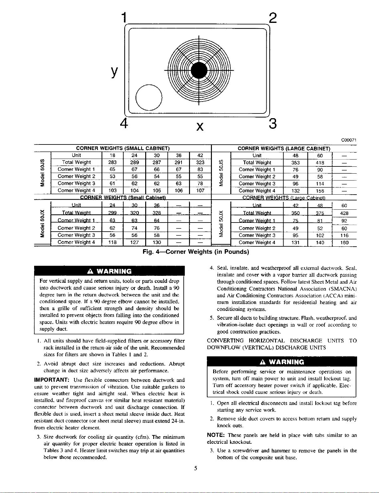
CORNER WEIGHTS (SMALL CABINET)
Unit 18 24 30 36 42
o
1=3
• Comer Weight 2
-o
o
:_ Comer Weight 3
o
"o
0
For vertical supply and return units, tools or parts could drop
into ductwork and cause serious injury or death. Install a 90
degree turn in the return ductwork between the unit and the
conditioned space. If a 90 degree elbow cannot be installed,
then a grille of sufficient strength and density should be
installed to prevent objects from falling into the conditioned
space. Units with electric heaters require 90 degree elbow in
supply duct.
1. All units should have field-supplied filters or accessory filter
2. Avoid abrupt duct size increases and reductions. Abrupt
IMPORTANT: Use flexible connectors between ductwork and
unit to prevent tr,'msmission of vibration. Use suitable gaskets to
ensure weather tight and airtight seal. When electric heat is
installed, usd fireproof canvas (or similar heat resistant material)
connector between ductwork and unit discharge connection. If
flexible duct is used, insert a sheet metal sleeve inside duct. Heat
resistant duct connector (or sheet metal sleeve) must extend 24-in.
from electric heater element.
3. Size ductwork for cooling air quantity (cfm). The minimum
Total Weight 283 289 287 291 323
Comer Weight 1 65 67 66 67 83
53 56 54 55 55
103 104 105 106 107
61 62 62 63 78
Corner Weight 4
CORNER WEIGHTS (Small Cabinetl
Unit 24 _O _{_
Total Weiaht -- --
Comer Weiaht 1 63 63 64 -- --
Comer Weight 2 62 74 76 -- --
Comer Weight 3 56 56 58 -- --
Comer Weight 4 118 127 130 -- --
299 320 328
m
Fig. 4---Corner Weights (in Pounds)
rack installed in the return-air side of the unit. Recommended
sizes for filters are shown in Tables 1 and 2.
change in duct size adversely affects air performance.
air quantity for proper electric heater operation is listed in
Tables 3 and 4. Heater limit switches may trip at air quantities
below those recommended.
X
CORNER WEIGHTS (LARGE CABINET)
03 Total Weight 353 418 --
Comer Weight 1 76 90 --
i nit 48 60 --
x Total Weinht 350 375 428
I °
m Comer Weiaht 1 75 81 92
3; Comer Weight 3 95 102 116
l _ Comer Weight 2 49 52 60
4. Seal, insulate, and weatherproof all external ductwork. Seal,
insulate and cover with a vapor barrier all ductwork passing
through conditioned spaces. Follow latest Sheet Metal and Air
Conditioning Contractors National Association ISMACNA)
and Air Conditioning Contractors Association {ACCA/mini-
mum installation standards for residential heating and air
conditioning systems.
5. Secure all ducts to building structure. Flash, weatherproof, and
vibration-isolate duct openings in wall or roof according to
good construction practices.
CONVERTING HORIZONTAL DISCHARGE UNITS TO
DOWNFLOW (VERTICAL) DISCHARGE UNITS
Before performing service or maintenance operations on
system, turn off main power to unit and install lockout tag.
Turn off accessory heater power switch if applicable. Elec-
trical shock could cause serious injury or death.
1. Open all electrical disconnects and install lockout tag before
starting any service work.
2. Remove side duct covers to access bottom return and supply
knock outs.
Comer Weight 2 49 58 --
Comer Weight 4 132 t 56 --
Comer Weight 3 96 t 14 --
CORNER WEIGHTS tLaroe Cahinel)
Comer Weight 4 131 t40 160
3
Unit 42 48 60
Tf ° '_ •
r!_lk,I-.I,1,11d_1
NOTE: These panels are held in place with tabs similar to an
electrical knockout.
3. Use a screwdriver and hammer to remove the panels in the
bottom of the composite unit base.
5
C00071
VAC unrl
base "_
_ _(NOTE A) _
supplied _
Roofir_ material supplied)
field suPPlied m
field su_l_d
_Cant strip field supplied
Ir_ulaUon (field
eu_i work
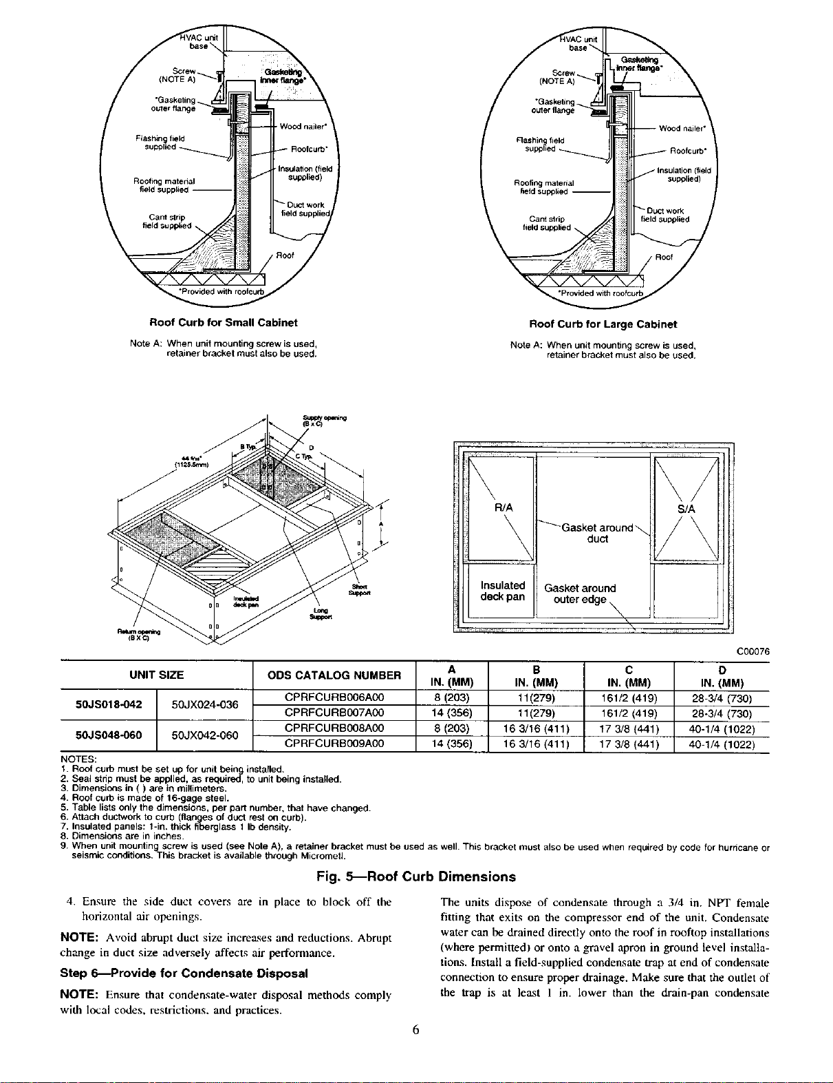
Roof Curb for Small Cabinet
Note A: When unit mounting screw is used,
retainer bracket must also be used.
Roof Curb for Large Cabinet
Note A: Whenunitmounting screwis used,
retainerbracketmustalsobe used.
R/A S/A
Insulated Gasket around
deck pan outer edge
C00076
UNIT SIZE
50JS018-042 50JX024-036
50JS048-060 50JX042-060
ODS CATALOG NUMBER
CPRFCURB006A00
CPRFCURS007A00
CPRFCURB008A00
CPRFCURB009A00
A
IN. (MM)
8 (203)
14 (386)
8 (203)
14 (356)
B
IN. (MM)
11(279)
11(279)
16 3/16 (411)
16 3/16 (411)
C
IN. (MM)
161/2 (419)
161/2 (419)
17 3/8 (441)
17 3/8 (441)
D
IN. (MM)
28-3/4 (730)
28-3/4 (730)
40-1/4 (1022)
40-1/4 (1022)
NOTES:
1. Roof curb must be set up for unit being installed.
2. Seal strip must be applied, as requiRd, to unit being installed.
3. Dimensions in ( ) are in millimeters.
4. Roof curb is made of 16-gage steel.
5. Table lists only the dimensions, per part number, that have changed.
6. Attach ductwork to curb (flanges of duct rest on curb).
7. Insulated panels: t-in. thick fiberglass 1 Ib density.
8. Dimensions are in inches.
9. When unit mounting screw is used (see Note A, a retainer bracket must be used as well• This bracket must also be used when required by code for hurricane or
seismic conditions. This bracket is available through MicrornetL
Fig. 5_Roof Curb Dimensions
4. Ensure the side duct covers are in place to block off the
horizontal air openings.
NOTE: Avoid abrupt duct size increases and reductions. Abrupt
change in duct size adversely affects air pedormance.
Step C0---Provide for Condensate Disposal
NOTE: Ensure that condensate-water disposal methods comply
with local codes, restrictions, and practices.
The units dispose of condensate through a 3/4 in. NPT female
fitting that exits on the compressor end of the unit. Condensate
water can be drained directly onto the roof in rooftop installations
(where permitted) or onto a gravel apron in ground level installa-
tions. Install a field-supplied condensate trap at end of condensate
connection to ensure proper drainage. Make sure that the outlet of
the trap is at least 1 in. lower than the drain-pan condensate
±
m
B
Fig. 6_Unit Leveling Tolerances
2 w
t
EVA,RCOIL COND.COIL
Fig. 7--Slab Mounting Detail
MAXIMUM ALLOWABLE
DIFFERENCE (in.)
A-B B-C A-C
1/4 1/4 1/4
C99065
C99096
Fig. 8---Threading Belt
connection to prevent the pan from overflowing. Prime the trap
with water. When using a gravel apron, make sure it slopes away
from the unit.
If the installation requires draining the condensate water away
from the unit. install a field-supplied 2-in. trap at the condensate
connection to ensure proper drainage. Condensate trap is available
as an accessory or is field-supplied. Make sure that the outlet of the
trap is at least 1 in. lower than the unit drain-pan condensate
connection to prevent the pan from overflowing. Connect a drain
trough using a minimum of field-supplied 3/4 in. PVC or
field-supplied 3/4 -in. copper pipe at outlet end of the 2 in. trap
(See Fig. 12). Do not undersize the tube. Pitch the drain trough
downward at a slope of at least 1 in. every 10 ft. of horizontal run.
Be sure to check the drain trough for leaks. Prime the trap at the
beginning of the cooling season start-up.
FEED
C99067
Step 7--Install Electrical Connections
The unit cabinet must have an uninterrupted, unbroken
electrical ground to minimize the possibility of personal
injury if an electrical fault should occur. This _ound may
consist of an electrical wire connected to the unit ground lug
in the control compartment, or conduit approved for electrical
ground when installed in accordance with NEC, ANSI/NFPA
American National Standards Institute/National Fire Protec
tion Association (latest edition) (in Canada, Canadian Elec-
trical Code CSA C22.1 ) and local electrical codes. Failure to
adhere to this warning could result in serious injury or death.
UNIT SIZE
NOMINAL CAPACITY (ton)
OPERATING WEIGHT (lb.)
COMPRESSOR QUANTITY
TYPE
REFRIGERANT
REFRIGERANT METERING DEVICE
Refrigerant (R-22) Quantity (Ib,)
ORIFICE ID (in.)
ORIFICE OD (in.)
OUTDOOR COIL
Rows,.. Fins/in,
Face Area (sq, ft.)
OUTDOOR FAN
Nominal Airflow (CFM)
Diameter
Motor HP (RPM)
INDOOR COIL
Rowe.., Fins/in.
Face Area (sq. ft.)
INDOOR BLOWER
Nominal Airflow (CFM)
Size (in,)
Motor (HP)
RETURN-AIR FILTERS (in.)
throwaway
C00139
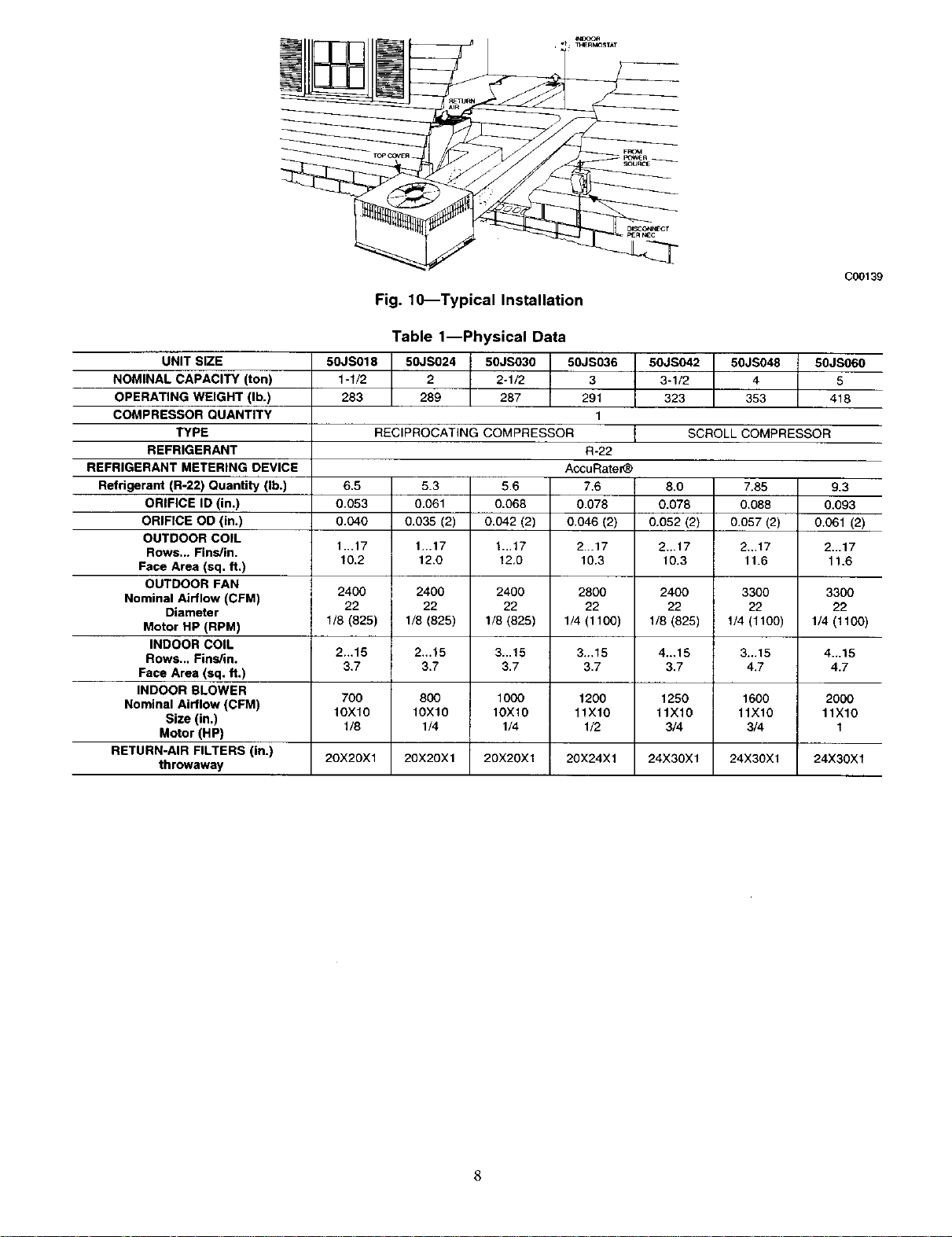
Fig. 10_Typical Installation
Table 1--Physical Data
50JS018 50JS024 50JS030 50JS036
1-1/2 2 2-1/2 3
283 289 287 291
1
RECIPROCATING COMPRESSOR I
6.5
0.053
0.040
1...17
10.2
2400 2400 2400 2800 3300
22 22 22 22 22
1/8 (825) 1/8 (825) 1_ (825) 1_ (1100) 1_ (1100)
2...15 2...15 3...15 3..,15 4...15
3.7 3.7 3.7 3.7 4.7
700 800 1000 1200 2000
IOXlO 10X10 10X10 11X10 11X10
20X20X1 20X20X1 20X2OX1 20X24X1 24X30X1
5.3
0.061
0.035 (2)
1...17
12.0
5.6
0.068
0.042 (2)
1...17
12,0
R-22
AccuRate_
7.6
0.078
0.046 (2)
2...17
10.3
50JS042 50JS048 50JS060
3-1/2 4 5
323 353 418
SCROLL COMPRESSOR
8.0 7.85
0.078 0.088
0.052 (2) 0.057 (2)
2...17 2...17
10.3 11.6
2400 3300
22 22
1/8 (625) 1/4 (1100)
4..,15 3...15
3.7 4.7
1250 1600
11X16 11X10
3/4 3/4
24X30X1 24X30X1
9.3
0,093
0.061 (2)
2...17
11.6
8
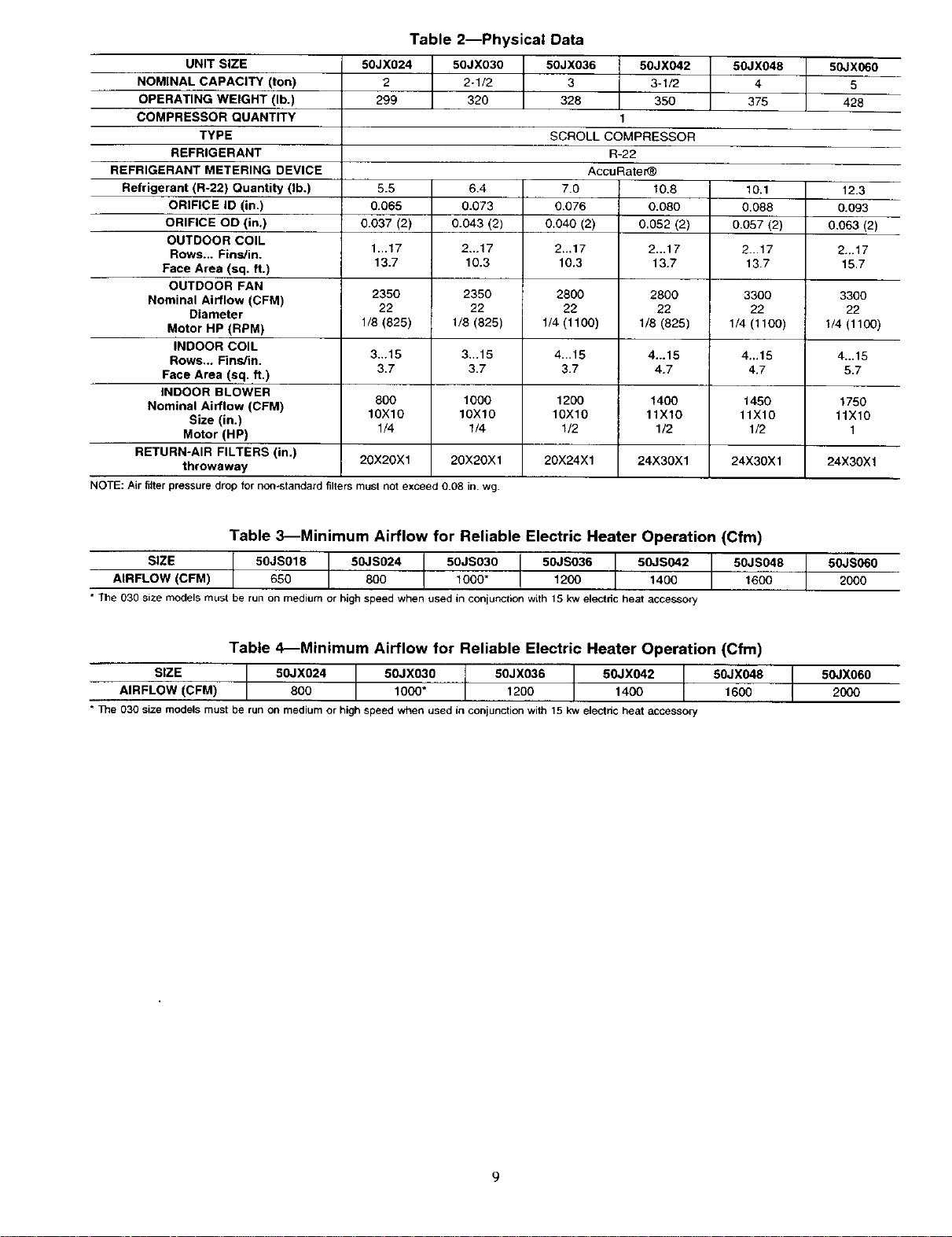
Table 2--Physical Data
UNIT SIZE
NOMINAL CAPACITY (ton)
OPERATING WEIGHT (lb.)
COMPRESSOR QUANTITY
TYPE
REFRIGERANT
REFRIGERANT METERING DEVICE
Refrigerant (R-22) Quantity (lb.)
ORIFICE ID (in,)
ORIFICE OD (in.)
OUTDOOR COIL
Rows... Fins/in.
Face Area (sq. ft.)
OUTDOOR FAN
Nominal Airflow (CFM)
Diameter
Motor HP (RPM)
INDOOR COIL
Rows... Fins/in.
Face Area (sq. ft.)
INDOOR BLOWER
Nominal Airflow (CFM)
Size (in.)
Motor (HP)
RETURN-AIR FILTERS (in.)
throwaway
NOTE: Air filter pressure drop for non-standard filters must not exceed 0.08 in. wg.
50JX024 50JX030 50JX036 50JX042
2 2-1/2 3 3-1/2
299 320 328 350
5.5 6.4 7.0 10.8
0.065 0.073 0.076 0.080
0.037 (2) 0.043 (2) 0.040 (2) 0.052 (2)
1...17 2...17 2-.17 2.,,17
13.7 10.3 10.3 13.7
2350 2350 2800 2800
22 22 22 22
1/8 (825) 1/8 (825) 1/4 (1100) 1/8 (825)
3,,.15 3.,.15 4...15 4-.15
3,7 3.7 3.7 4.7
800 1000 1200 1400
10X10 10X10 10X10 11X10
1/4 1/4 1/2 1/2
20X20X1 20X20X1 20X24X1 24X30Xl
1
SCROLL COMPRESSOR
R-22
AccuRate_
50JX048
375
10.1 12.3
0.088 0.093
0.057 (2) 0,063 (2)
2...17 2._17
13.7 15.7
3300 3300
22 22
1/4(1100) 1/4(1100)
4...15 4.,.15
4.7 5.7
1450 1750
11X10 11X10
1/2 1
24X30X1 24X30X1
50JX060
5
428
Table 3_Minimum Airflow for Reliable Electric Heater Operation (Cfm)
SIZE 50JS018 50JS024 50JS030 50JS036 50JS042 50JS048
AIR FLOW (CFM) 650 800 1000" 1200 1400 1600
• The 030 size models must be run on medium or highspeedwhen usedin conjunctionwith15 kwelectdc heat accessory
Table 4_Minimum Airflow for Reliable Electric Heater Operation (Cfm)
SIZE 50JX024 50JXO30 50JX036 50JX042 50JX048
AIRFLOW (CFM) 800 1000" 1200 1400 1600
* The 030 size modelsmust be runon medium or high speed when usedin conjunction with15 kw electdcheat accessory
50JS060
2000
50JXO6O
2000
9
L SEE DETAIL A
UNIT
Size
50JS018
50JS024
50JS03O
50JS036
50JS042
50JSO48
5OJS060
50JX024
50JX030
50JX036
50JX042
50JX048
50JX060
(36" 54"/
TIGHTEN STRAPPING SECURELY
WITH TENS}ON BUCKLE
INSTALL SAFETY STRAPS TO
RIGGING CLEVIS AT 4 RIGGING BRACKETS
PLACE RIGGING BRACKET ASSEMBLY {N 4
RIGGING HOLES AND iNSTALL TIE DOWN STRAP
AROUND PERIMETER OF UNIT AN{] THROUGH
SPACE IN BRACKET ASSEMBLY
MAXIMUM WEIGHT
INCLUDES SHIPPING SKID A
Ib kg in. ram.
305 138.4 19.5 495.3
311 141.1 18.5 469.9
309 140.2 19.5 495.3
313 142.0 19.5 495.3
345 156.4 19.5 495.3
375 170.1 20.5 520.7
440 199.6 19,5 4953
321 145.6 19.0 482.6
342 155.2 20.0 508
350 158.8 20.0 508
372 168.8 21.0 533.4
377 171.0 20.0 508
450 204.2 21.0 533.4
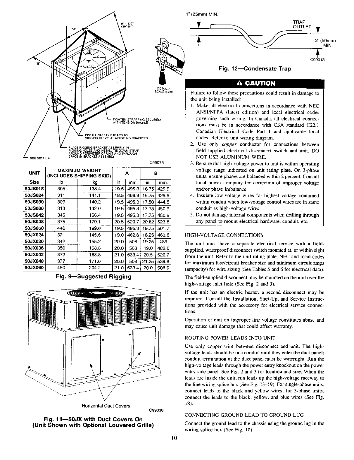
Fig, 9_Suggested Rigging
OETAIL A
SCALF 0250
C99075
B
in. mm.
16.75 425.5
16.75 425,5
1730 444.5
17.75 450.9
17.75 450.9
20.62 523.8
19.75 501.7
18.25 463.6
19.25 489
19.0 482.6
20.5 520.7
21.25 539.8
20.0 508.0
1" (25ram) MIN.
TRAP
OUTLET +
]
2" (50ram)
C99013
Fig. 12_ondensate Trap
Failure to follow these precautions could result in damage to
the unit being installed:
1. Make all electrical connections in accordance with NEC
ANSI/NFPA (latest edition) and local electrical codes
governing such wiring. In Canada, all electrical connec-
tions must be in accordance with CSA standard C22.1
Canadian Electrical Code Part 1 and applicable local
codes. Refer to unit wiring diagram.
2. Use only copper conductor for connections between
field supplied electrical disconnect switch and unit. DO
NOT USE ALUMINUM WIRE.
3. Be sure that high-voltage power to unit is within operating
voltage range indicated on unit rating plate. On 3-phase
units, ensure phases are balanced within 2 percent. Consult
local power company for correction of improper voltage
and/or phase imbalance.
4. Insulate low-voltage wires for highest voltage contained
within conduit when low-voltage control wires are in same
conduit as high-voltage wires.
5. Do not damage internal components when drilling through
any panel to mount electrical hardware, conduiL etc.
HIGH-VOLTAGE CONNECTIONS
The unit must have a separate electrical service with a field-
supplied, waterproof disconnect switch mounted at, or within sight
from the unit. Refer to the unit rating plate, NEC and local codes
for maximum fuse/circuit breaker size and minimum circuit amps
(ampacity) for wire sizing (See Tables 5 and 6 for electrical data).
The field-supplied disconnect may be mounted on the unit over the
high-voltage inlet hole (See Fig. 2 and 3).
If the unit has an electric heater, a second disconnect may be
required. Consult the Installation, Start-Up, and Service Instruc-
tions provided with the accessory for electrical service connec-
tions.
Operation of unit on improper line voltage constitutes abuse and
may cause unit damage that could affect warranty.
MIN.
Horizontal Duct Covers
Fig. 11--50JX with Duct Covers On
(Unit Shown with Optional Louvered Grille)
ROUTING POWER LEADS INTO UNIT
Use only copper wire between disconnect and unit. The high-
voltage leads should be in a conduit until they enter the duct panel;
conduit terntination at the duct panel must be watertight. Run the
high-voltage leads through the power entry knockout on the power
entry side panel. See Fig. 2 and 3 for location and size. When the
leads are inside the unit. run leads up the high-voltage raceway to
the line wiring splice box (See Fig. 13-19). For single-phase units,
connect leads to the black and yellow wives: for 3-phase units,
connect the leads to the black, yellow, and blue wires (See Fig.
|8).
C99030
CONNECTING GROUND LEAD TO GROUND LUG
Connect the ground lead to the chassis using the ground lug in the
wiring splice box ISee Fig. 18).
10
 Loading...