

Carrier 50HS018, 50HS024, 50HS036, 50HS042, 50HS048 Installation, Start-up And Service Instructions Manual
...Page 1
Installation, Start-Up and
Service Instructions
CONTENTS
Page
SAFETY CONSIDERATIONS .................1-6
General ......................................1
RECEIVING AND INSTALLATION ............7-17
Step 1 — Check Equipment ...................7
• IDENTIFY UNIT
• INSPECT SHIPMENT
Step 2 — Provide Unit Support ...............7
• ROOF CURB
• SLAB MOUNT
Step 3 — Provide Clearances .................7
Step 4 — Rig and Place Unit ..................8
• UNITS WITHOUT BASE RAILS
• UNITS WITH OPTIONAL BASE RAILS
Step 5 — Select and Install Ductwork ........10
• CONVERTING HORIZONTAL DISCHARGE
UNITS TO DOWNFLOW (VERTICAL)
DISCHARGE
• ACCESSORY DUCT FLANGE KIT
INSTALLATION
Step 6 — Provide for Condensate Disposal ...14
Step 7 — Install Electrical Connections ......14
• HIGH-VOLTAGE CONNECTIONS
• ROUTING POWER LEADS INTO UNIT
• CONNECTING GROUND LEAD TO
GROUND LUG
• ROUTING CONTROL POWER WIRES (24 v)
• SPECIAL PROCEDURES FOR 208-V
OPERATION
PRE-START-UP .............................17
START-UP ................................18-27
Check for Refrigerant Leaks .................18
Unit Start-Up Adjustments ...................18
MAINTENANCE ............................28-31
Air Filter ....................................28
Unit Top Removal ...........................28
Indoor Blower and Motor ....................28
Outdoor Coil, Indoor Coil, and Condensate
Drain Pan .................................29
Outdoor Fan ................................29
Electrical Controls and Wiring ...............29
Refrigerant Circuit ..........................29
Indoor Airflow ..............................30
Metering Devices ...........................30
Liquid Line Strainers ........................30
START-UP CHECKLIST .....................CL-1
NOTE TO INSTALLER — Before the installation, READ
THESE INSTRUCTIONS CAREFULLY AND COMPLETELY. Also, make sure the Owner’s Manual and Service Instructions are left with the unit after installation.
SAFETY CONSIDERATIONS
Installation and servicing of air-conditioning equipment
can be hazardous due to systempressure and electrical components. Only trained and qualified personnel should install,
repair, or service air-conditioning equipment.
Untrained personnel can perform basic maintenance functions of cleaning coils and filters.All other operations should
be performed by trained service personnel. When working
on air-conditioning equipment, observe precautions in the
literature, tags and labels attached to the unit, and other safety
precautions that may apply.
Follow all safety codes.W earsafetyglasses and work gloves.
Use quenching cloth for unbrazing operations. Have fire extinguisher available for all brazing operations.
Before performing service or maintenance operations on
system, turn off main power to unit. Turn off accessory
heater power switch if applicable. Electrical shock can
cause personal injury.
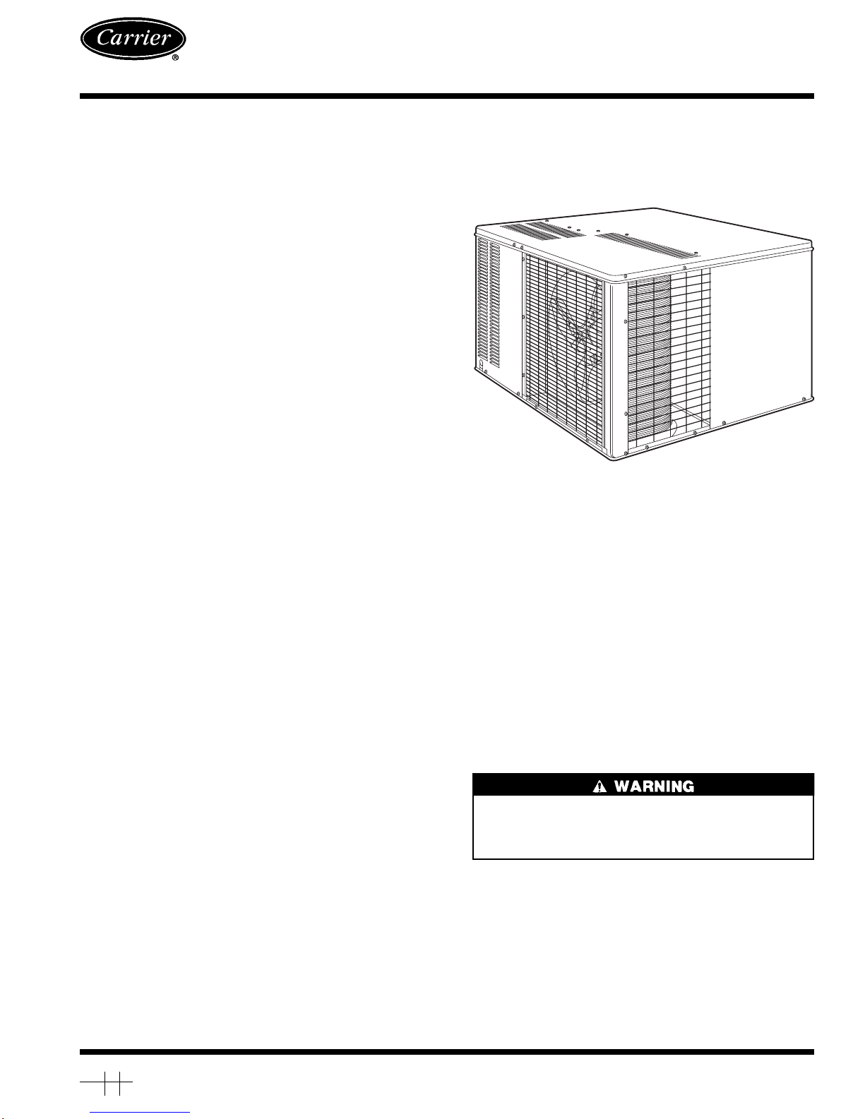
General — 50HS heat pumps are fully self-contained and
designed for outdoor installation. See Fig. 1. As shown in
Fig. 2-5, all units are shipped in a horizontal-discharge configuration for installation on a ground-level slab. All units
can be converted to downflow (vertical) discharge configurations for rooftop applications. See Fig. 6 for roof curb
dimensions.
Fig. 1 — Model 50HS
50HS018-060
Single-Package Heat Pump Units
Manufacturer reserves the right to discontinue, or change at any time, specifications or designs without notice and without incurring obligations.
Book 1 4
Tab 5a 5a
PC 111 Catalog No. 565-041 Printed in U.S.A. Form 50HS-9SI Pg 1 2-97 Replaces: 50HS-8SI
Page 2
UNIT
ELECTRICAL
CHARACTERISTICS
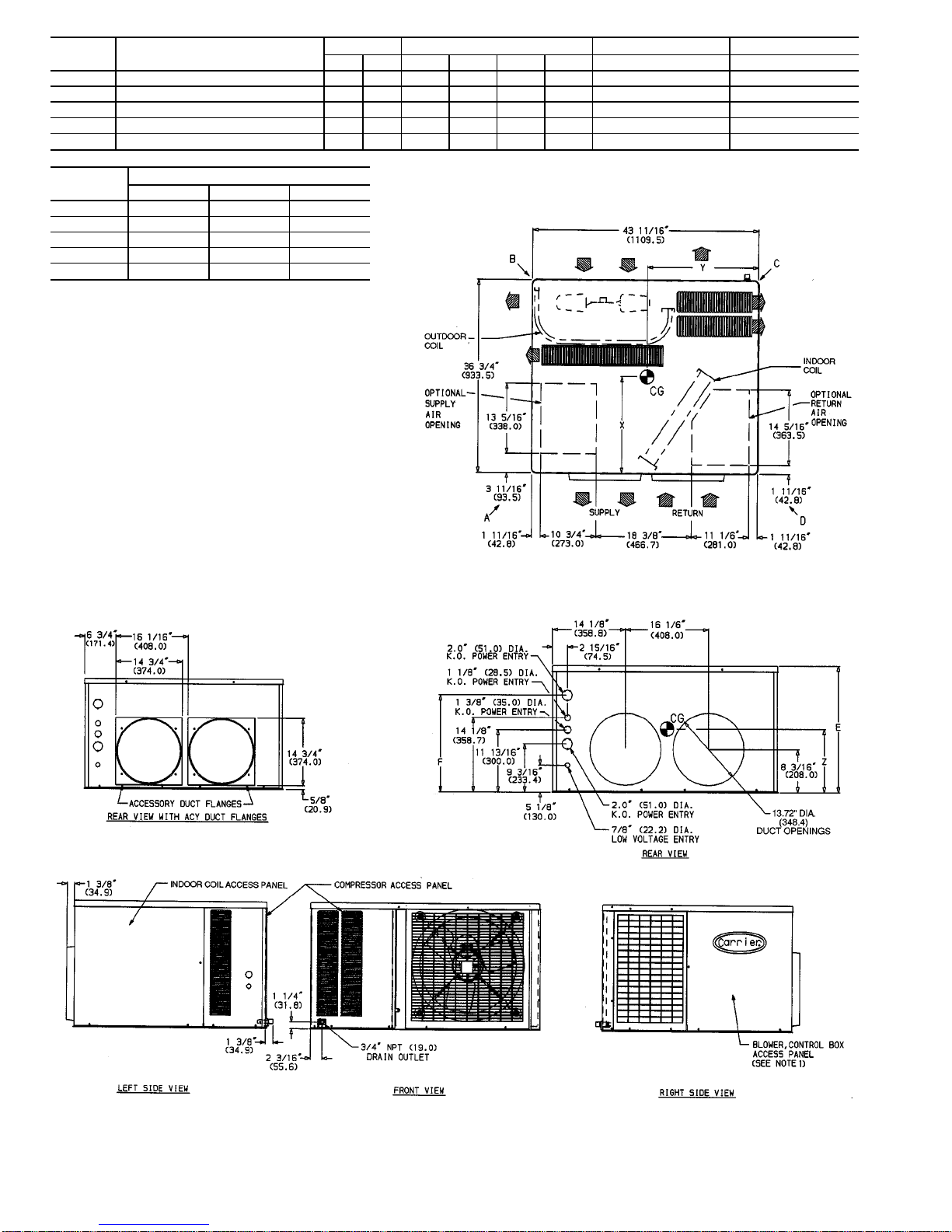
UNIT WT CORNER WT (Lb/Kg) UNIT HEIGHT (in./mm) DIMENSION (in./mm)
LbKgABCD E F
50HS018 208/230-1-60 233 106 66/30 45/20 95/43 42/19 24.1/613 18.2/462
50HS024 208/230-1-60 256 117 68/31 46/21 97/44 45/20 24.1/613 18.2/462
50HS030 208/230-1-60, 208/230-3-60 268 122 66/30 58/26 91/41 53/24 24.1/613 18.2/462
50HS036 208/230-1-60, 208/230-3-60, 460-3-60 288 131 71/32 63/29 96/44 58/26 28.1/714 22.2/563
50HS042 208/230-1-60, 208/230-3-60, 460-3-60 295 134 73/33 65/30 97/44 60/27 28.1/714 22.2/563
UNIT
CENTER OF GRAVITY (in./mm)
XYZ
50HS018 20.7/525 19.2/487 10.6/270
50HS024 20.4/517 19.3/491 10.6/270
50HS030 20.3/515 20.1/510 10.6/270
50HS036 20.1/511 20.2/513 12.4/314
50HS042 20.0/509 20.3/516 12.4/314
REQ’D CLEARANCES FOR SERVICING — in. (mm)
Indoor Coil Access Side .................30(762)
Control Box Access Side ................30(762)
(Except for NEC requirements)
Unit Top .........................36(914)
Side Opposite Ducts ..................30(762)
REQ’D CLEARANCES TO COMBUSTIBLE MAT’L — in. (mm)
Unit Top .............................0
Duct Side of Unit ........................0
Side Opposite Ducts ......................0
Bottom of Unit .........................0
Vertical Discharge, First 12 in. (305) of Supply Duct . . . 1 (25)
NEC REQ’D CLEARANCES — in. (mm)
Between Units, Control Box Side ...........42(1067)
Unit and Ungrounded Surfaces, Control Box Side . . . .36 (914)
Unit and Block or Concrete Walls and Other
Grounded Surfaces, Control Box Side ........42(1067)
LEGEND
CG — Center of Gravity
MAT’L — Material
NEC — National Electrical Code
REQ’D — Required
NOTE: Clearances must be maintained to prevent recirculation of
air from outdoor-fan discharge.
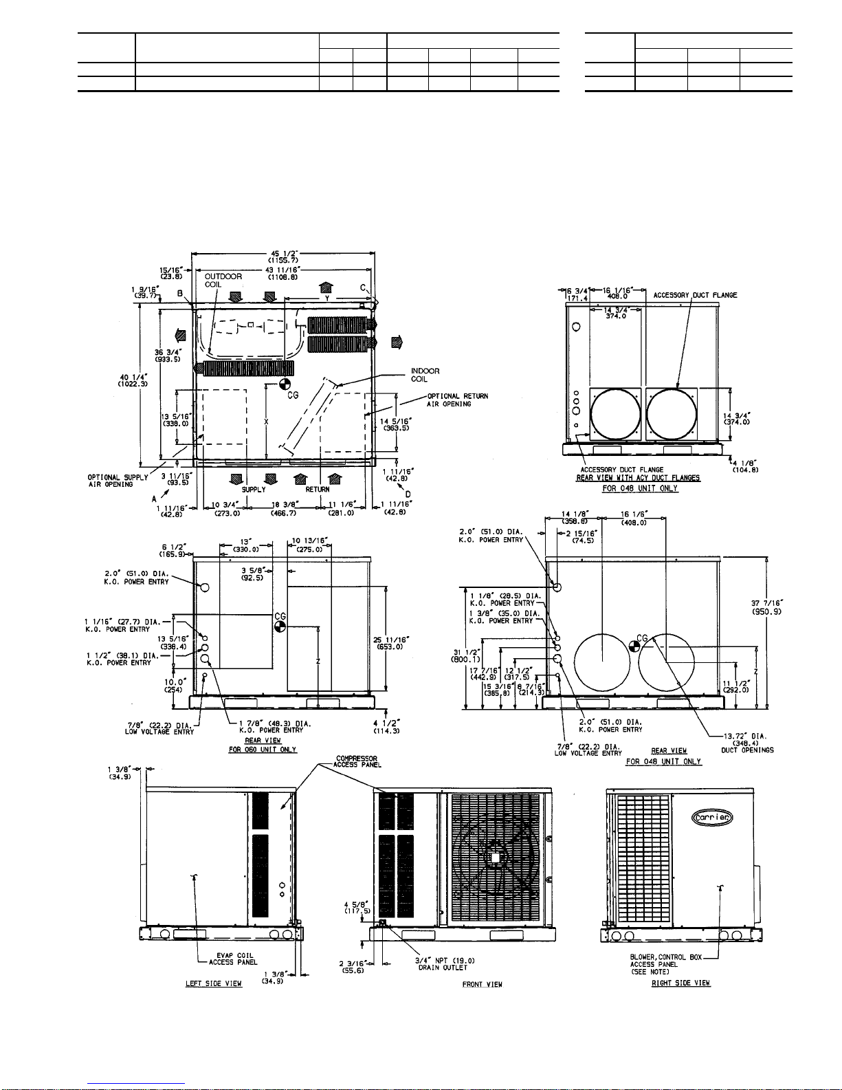
Fig. 2 — Dimensions; Sizes 018-042; Without Base Rail
2
Page 3
UNIT
ELECTRICAL
CHARACTERISTICS
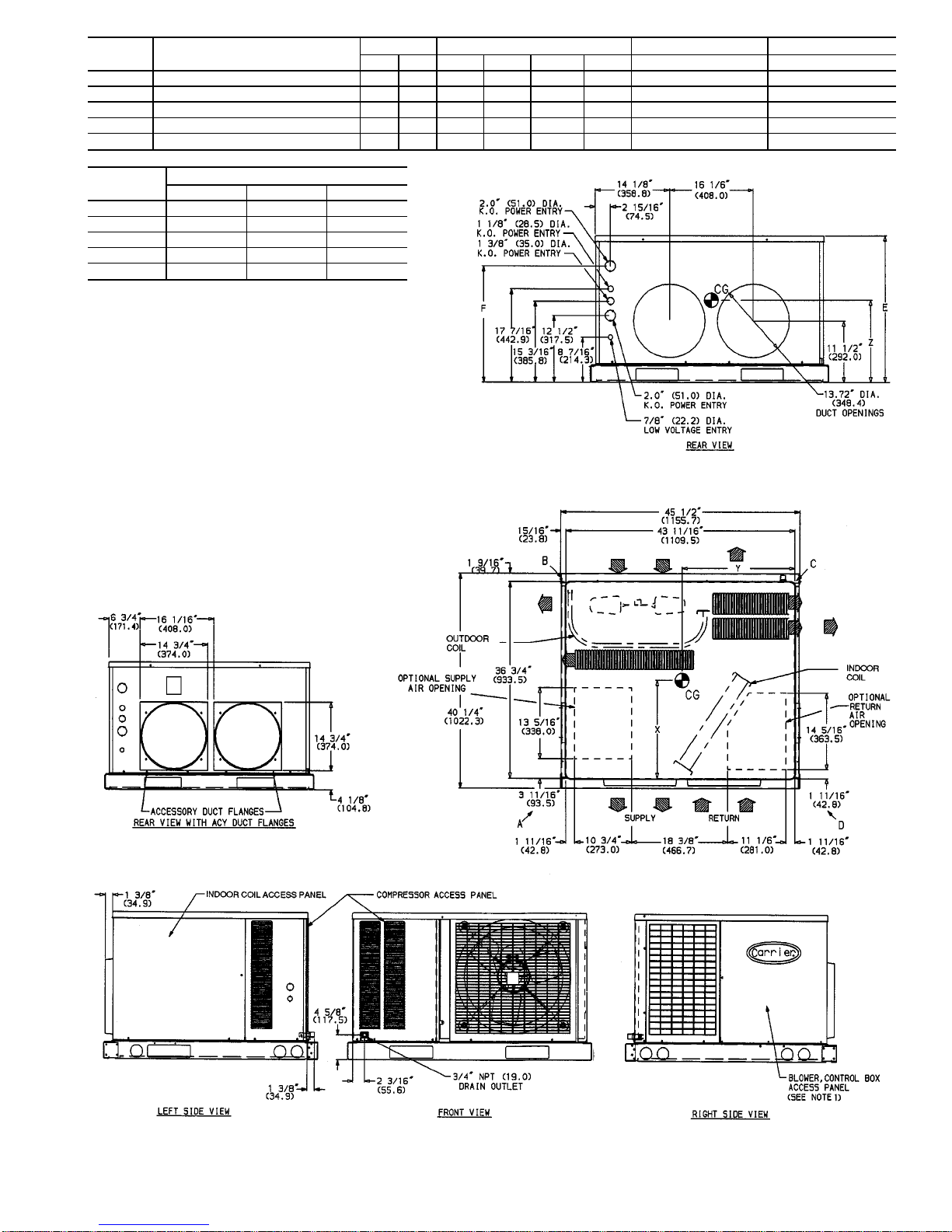
UNIT WT CORNER WT (Lb/Kg) UNIT HEIGHT (in./mm) DIMENSION (in./mm)
Lb Kg A B C D E F
50HS018 208/230-1-60 268 122 70/32 50/23 100/45 48/22 27.43/697 21.50/546
50HS024 208/230-1-60 276 125 73/33 51/23 102/46 50/23 27.43/697 21.50/546
50HS030 208/230-1-60, 208/230-3-60 288 131 71/32 63/29 96/44 58/26 27.43/697 21.50/546
50HS036 208/230-1-60, 208/230-3-60, 460-3-60 308 140 76/35 68/31 101/46 63/29 31.43/798 25.50/648
50HS042 208/230-1-60, 208/230-3-60, 460-3-60 315 143 78/35 70/32 102/46 65/30 31.43/798 25.50/648
UNIT
CENTER OF GRAVITY (in./mm)
XYZ
50HS018 20.4/518 19.4/493 12.9/329
50HS024 20.2/513 19.5/495 12.9/329
50HS030 20.1/511 20.2/513 12.9/329
50HS036 20.0/508 20.3/515 14.7/373
50HS042 19.9/506 20.4/518 14.7/373
REQ’D CLEARANCES FOR SERVICING — in. (mm)
Indoor Coil Access Side .................30(762)
Control Box Access Side ................30(762)
(Except for NEC requirements)
Unit Top .........................36(914)
Side Opposite Ducts ..................30(762)
REQ’D CLEARANCES TO COMBUSTIBLE MAT’L — in. (mm)
Unit Top .............................0
Duct Side of Unit ........................0
Side Opposite Ducts ......................0
Bottom of Unit .........................0
Vertical Discharge, First 12 in. (305) of Supply Duct . . . 1 (25)
NEC REQ’D CLEARANCES — in. (mm)
Between Units, Control Box Side ...........42(1067)
Unit and Ungrounded Surfaces, Control Box Side . . . .36 (914)
Unit and Block or Concrete Walls and Other
Grounded Surfaces, Control Box Side ........42(1067)
LEGEND
CG — Center of Gravity
MAT’L — Material
NEC — National Electrical Code
REQ’D — Required
NOTE: Clearances must be maintained to prevent recirculation of
air from outdoor-fan discharge.
Fig. 3 — Dimensions; Sizes 018-042; With Optional Base Rail
3
Page 4
UNIT
ELECTRICAL
CHARACTERISTICS
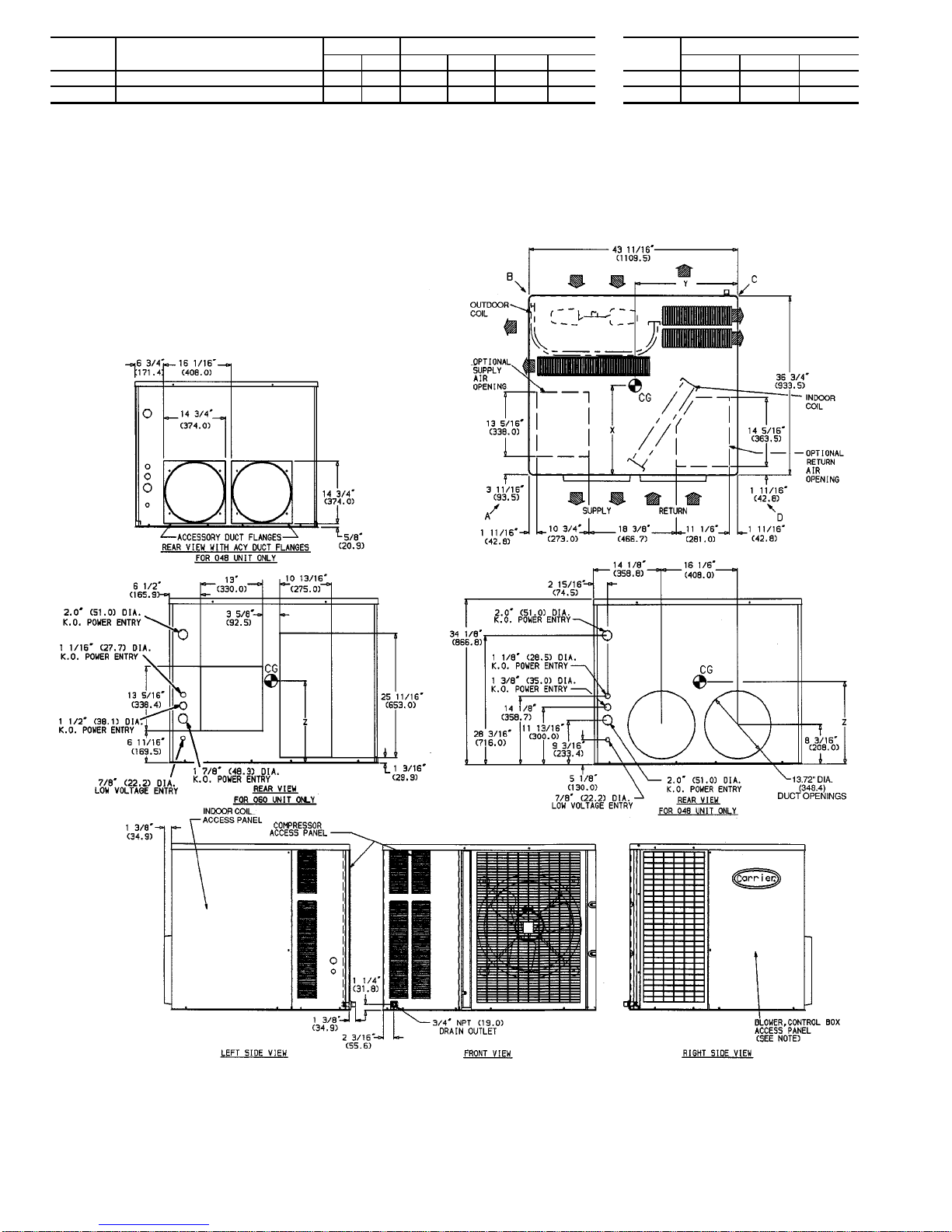
UNIT WT CORNER WT (Lb/Kg)
Lb Kg A B C D
50HS048 208/230-1-60, 208/230-3-60, 460-3-60 359 163 89/40 81/37 113/51 76/35
50HS060 208/230-1-60, 208/230-3-60, 460-3-60 373 170 92/42 85/39 116/53 80/36
UNIT
CENTER OF GRAVITY (in./mm)
XYZ
50HS048 19.7/500 20.5/522 15.0/381
50HS060 19.7/499 20.6/523 15.0/381
REQ’D CLEARANCES FOR SERVICING — in. (mm)
Indoor Coil Access Side .................30(762)
Control Box Access Side ................30(762)
(Except for NEC requirements)
Unit Top .........................36(914)
Side Opposite Ducts ..................30(762)
REQ’D CLEARANCES TO COMBUSTIBLE MAT’L — in. (mm)
Unit Top .............................0
Duct Side of Unit ........................0
Side Opposite Ducts ......................0
Bottom of Unit .........................0
Vertical Discharge, First 12 in. (305) of Supply Duct . . . 1 (25)
NEC REQ’D CLEARANCES — in. (mm)
Between Units, Control Box Side ...........42(1067)
Unit and Ungrounded Surfaces, Control Box Side . . . .36 (914)
Unit and Block or Concrete Walls and Other
Grounded Surfaces, Control Box Side ........42(1067)
LEGEND
CG — Center of Gravity
MAT’L — Material
NEC — National Electrical Code
REQ’D — Required
NOTE: Clearances must be maintained to prevent
recirculation of air from outdoor-fan discharge.
Fig. 4 — Dimensions; Sizes 048,060; Without Base Rail
4
Page 5
UNIT
ELECTRICAL
CHARACTERISTICS
UNIT WT CORNER WT (Lb/Kg)
Lb Kg A B C D
50HS048 208/230-1-60, 208/230-3-60, 460-3-60 379 172 94/43 86/39 118/54 81/37
50HS060 208/230-1-60, 208/230-3-60, 460-3-60 393 179 97/44 90/41 121/55 85/39
UNIT
CENTER OF GRAVITY (in./mm)
XYZ
50HS048 19.6/498 20.6/524 17.3/440
50HS060 19.6/497 20.6/524 17.3/440
REQ’D CLEARANCES FOR SERVICING — in. (mm)
Indoor Coil Access Side .................30(762)
Control Box Access Side ................30(762)
(Except for NEC requirements)
Unit Top .........................36(914)
Side Opposite Ducts ..................30(762)
REQ’D CLEARANCES TO COMBUSTIBLE MAT’L — in. (mm)
Unit Top .............................0
Duct Side of Unit ........................0
Side Opposite Ducts ......................0
Bottom of Unit .........................0
Vertical Discharge, First 12 in. (305) of Supply Duct . . . 1 (25)
NEC REQ’D CLEARANCES — in. (mm)
Between Units, Control Box Side ...........42(1067)
Unit and Ungrounded Surfaces, Control Box Side . . . .36 (914)
Unit and Block or Concrete Walls and Other
Grounded Surfaces, Control Box Side ........42(1067)
LEGEND
CG — Center of Gravity
MAT’L — Material
NEC — National Electrical Code
REQ’D — Required
Fig. 5 — Dimensions; Sizes 048,060; With Optional Base Rail
NOTE: Clearances must be maintained to prevent
recirculation of air from outdoor-fan discharge.
5
Page 6
PART NUMBER ‘‘A’’
Flat
CPRFCURB001A00 89 [203]
CPRFCURB002A00 119 [279]
CPRFCURB003A00 149 [356]
NOTES:
1. Roof curb must be set up for unit being installed.
2. Seal strip must be applied as required for unit being installed.
3. Dimensions in [ ] are in millimeters.
4. Roof curb is made of 16 gage steel.
5. Attach ductwork to curb (flanges of duct rest on curb).
6. Service clearance 4 ft on each side.
7. Direction of airflow.
8. Insulated panels: 1-in. thick fiberglass, 1-lb density.
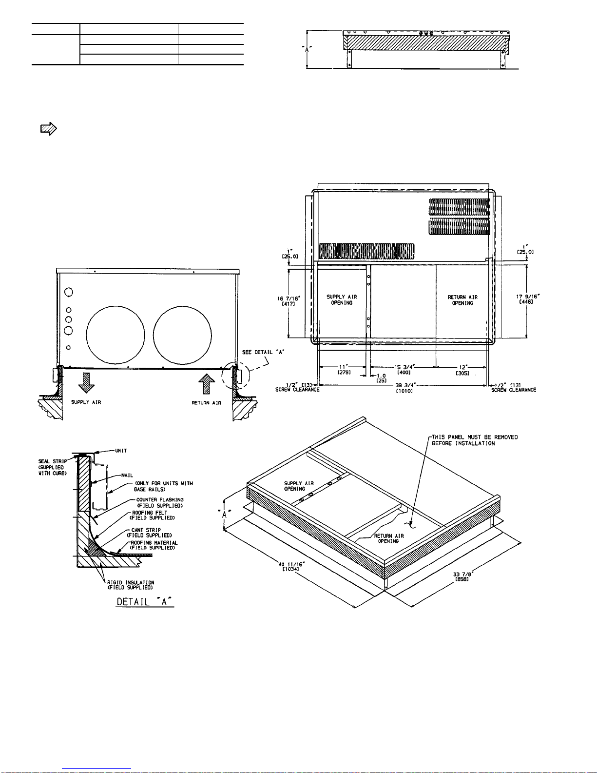
Fig. 6 — Roof Curb Dimensions
6
Page 7
RECEIVING AND INSTALLATION
Step 1 — Check Equipment
IDENTIFYUNIT — The unit model number and serial number are stamped on the unit identification plate. Check this
information against shipping papers.
INSPECT SHIPMENT — Inspect for shipping damage while
unit is still on shipping pallet. If unit appears to be damaged
or is torn loose from its anchorage, have it examined by transportation inspectors before removal. Forward claim papers
directly to transportation company. Manufacturer is not responsible for any damage incurred in transit.
Check all items against shipping list. Immediately notify
the nearest Carrier Air Conditioning office if any item is
missing.
To prevent loss or damage, leave all parts in original packages until installation.
Step 2 — Provide Unit Support
ROOF CURB — Install accessory roof curb in accordance
with instructions shipped with curb. See Fig. 6. Install insulation, cant strips, roofing, and flashing. Ductwork must
be attached to curb.
IMPORTANT: The gasketing of the unit to the roof
curb is critical for a watertight seal. Install gasketing
material supplied with the roof curb. Improperly applied gasketing also can result in air leaks and poor
unit performance.
Curb should be level to within1⁄4inch. This is necessary
for unit drain to function properly. Refer to accessory roof
curb installation instructions for additional information as
required.
SLAB MOUNT — Place the unit on a solid, level concrete
pad that is a minimum of 4 in. thick with 2 in. above grade.
The slab should extend approximately 2 in. beyond the casing on all 4 sides of the unit. Install a 6-in. gravel apron in
front of outdoor coil air inlet to prevent obstruction of airflow by grass or shrubs. Do not secure the unit to the slab
except when required by local codes. In areas where prolonged subfreezing temperatures or snowfall occur, increase
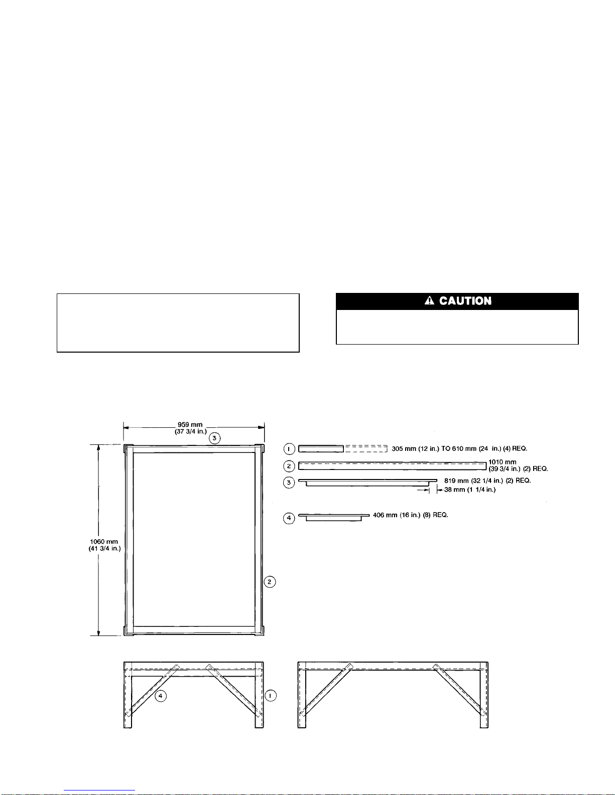
clearance to 12 to 18 in. by constructing an angle-iron frame
to support unit. See Fig. 7 for recommended frame construction. Alternate construction should follow dimensions provided in Fig. 7.
Step 3 — Provide Clearances — The required mini-
mum service clearances and clearances to combustibles are
shown in Fig. 2-5. Adequate ventilation and outdoor air must
be provided.
The outdoor fan pushes air through the outdoor coil and
discharges it through louvers on the top cover, the decorative grille, and the compressor access panel. Be sure that the
fan discharge does not recirculate to the outdoor coil. Do not
locate the unit in either a corner or under an overhead obstruction. The minimum clearance under a partial overhang
(such as a normal house overhang) is 48 in. above the unit
top. The maximum horizontal extension of a partial overhang must not exceed 48 inches.
Do not restrict outdoor airflow. An air restriction at either the outdoor-air inlet or the fan discharge can be detrimental to compressor life.
Do not place the unit where water, ice, or snow from an
overhang or roof will damage or flood the unit. Do not install the unit on carpeting, tile, or other combustible materials. The unit may be installed on wood flooring or on Class
A, B, or C roof covering materials.
Fig. 7 — Heat Pump Mounting Frame
NOTES:
1. Material consists of angle iron — 31.8 mm (11⁄4in.) to 38 mm (11⁄2in.)
commercial standard.
2 Weld frame together.
3. Paint with zinc-rich paint (rustproof).
7
Page 8
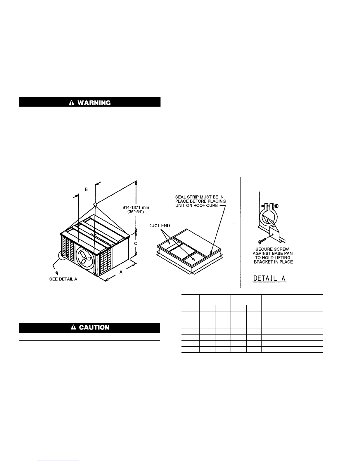
Step 4 — Rig and Place Unit — Use spreader bars
or crate top when rigging the unit. The units must be rigged
for lifting as shown in Fig. 8 and 9. Refer to Fig. 8 and 9 and
T able1for rigging weights. See Fig. 2-5 for operating weights.
Use extreme caution to prevent damage when moving the
unit. Unit must remain in an upright position during all rigging and moving operations. The unit must be level for proper
condensate drainage; the ground-level pad or accessory roof
curb must be level before setting the unit in place. When a
field-fabricated support is used, be sure that the support is
level and that it properly supports the unit.
UNITSWITHOUT BASE RAILS — Accessory rigging brackets are recommended to be used for rigging.
Secure screws and paint protectors solidly against unit
basepan to hold lifting brackets in position.
Never use lifting brackets when the temperature is
below −10 F.
Never exceed 200 lbs per bracket of lifting force.
Never use lifting brackets for lifting other models of air
conditioning units.
Lifting point should be directly over the unit center of
gravity.
Install accessory rigging brackets as follows:
1. Position brackets as close to the corners of unit as possible. Be sure brackets are well outside of center of gravity. (See Fig. 2, 4, and 8.)
2. Position paint protectors and foam strips between screws
and painted surface of unit. Tightenscrews until they make
contact with the paint protectors.
3. Securedevice or hook of sufficientstrength to hole in bracket
as shown in detail ‘‘A’’ of Fig. 8.
4. If wood top is available, use it for a spreader bar to prevent straps from damaging unit. If wood top is not available, use spreader bars of sufficient length.
UNITS WITH OPTIONAL BASE RAILS — Keep unit upright and do not drop. Use spreader bars or top crate when
rigging unit. Rollers may be used to move unit across roof.
The unit must be level for proper condensate disposal. Rig
unit as shown in Fig. 9. See Fig. 3 and 5 for additional information. Lifting holes are provided in base rails as shown
in Fig. 9. Refer to rigging instructions on unit.
NOTICE TO RIGGERS
Hook rigging shackles through holes in lifting brackets, as shown in
detail ‘‘A.’’ Lifting brackets to be centered around the unit center of
gravity. Use wood top skid when rigging, to prevent rigging straps
from damaging unit.
All panels MUST be in place when rigging.
UNIT
50HS
SIZE
SHIPPING
WEIGHT
ABC
Lb Kg in. mm in. mm in. mm
018 300 136 36.8 934 17.3 439 24.1 613
024 308 140 36.8 934 16.1 409 24.1 613
030 320 145 36.8 934 16.1 411 24.1 613
036 340 154 36.8 934 16.3 415 28.1 714
042 347 157 36.8 934 16.5 417 28.1 714
048 411 186 36.8 934 16.8 426 34.1 867
060 425 193 36.8 934 16.8 427 34.1 867
Fig. 8 — Suggested Rigging for Units Without Base Rail
8
Page 9
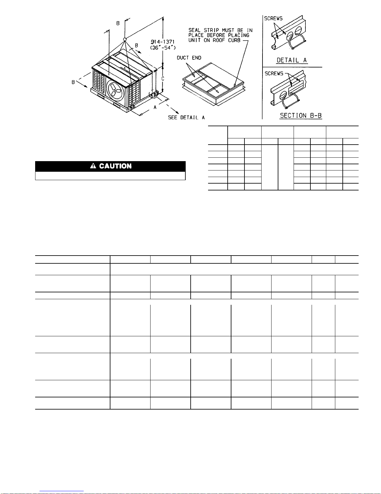
Table 1 — Physical Data
UNIT 50HS 018 024 030 036 042 048 060
REFRIGERANT R-22
Refrigerant Control* Acutrol™ System
SHIPPING WEIGHT (lb)
Without Base Rails 300 308 320 340 347 411 425
With Optional Base Rails 287 295 307 327 334 398 412
COMPRESSOR TYPE Reciprocating Reciprocating Reciprocating Reciprocating Reciprocating Scroll Scroll
INDOOR FAN Centrifugal — Direct Drive
Speeds 2333222
Rpm (High Speed) 825 1025 1025 1100 1100 1100 1100
Diameter (in.) 10 10 10 10 10 10 10
Width (in.) 999991010
Nominal Airflow (Cfm) 675 800 1000 1300 1400 1600 1995
Motor Hp
1
⁄
4
1
⁄
4
1
⁄
4
1
⁄
2
3
⁄
4
3
⁄
4
1
INDOOR COIL
Rows...Fins/in. 3...15 3...15 3...15 3...15 3...15 3...15 4...15
Face Area (sq ft) 1.83 2.29 3.06 2.70 3.60 4.50 4.50
OUTDOOR FAN Propeller — Direct Drive
Cfm 1700 1900 1900 1900 1900 2400 2400
Rpm 850 1050 850 1050 1050 1050 1050
Diameter (in.) 18 18 18 18 20 20 20
Motor Hp
1
⁄
8
1
⁄
4
1
⁄
4
1
⁄
4
1
⁄
4
1
⁄
3
1
⁄
3
OUTDOOR COIL
Rows...Fins/in. 2...17 2...17 2...17 2...17 2...17 2...17 2...17
Face Area (sq ft) 5.7 5.7 5.7 6.7 6.7 8.2 8.2
FILTER SIZE (in.)†
Throwaway 20x20 20x20 20x24 24x24 24x24 24x30 24x30
*Operating charge listed on unit nameplate.
†Recommended field-supplied filters are 1 in. thick.
NOTICE TO RIGGERS
Hook rigging shackles through holes in lifting brackets, as shown in
detail ‘‘A.’’ Lifting brackets to be centered around the unit center of
gravity. Use wood top skid when rigging, to prevent rigging straps
from damaging unit. Remove 4 screws to slide wood support through
rectangular hole in rail.
All panels must be in place when rigging.
UNIT
50HS
SIZE
SHIPPING
WEIGHT
ABC
Lb Kg in. mm in. mm in. mm
018 287 130
36.5 926
16.1 408 28.2 715
024 295 134 16.3 413 28.2 715
030 307 139 16.3 415 28.2 715
036 327 148 16.5 418 32.2 817
042 334 151 16.5 420 32.2 817
048 398 180 16.9 428 38.2 969
060 412 187 16.9 429 38.2 969
Fig. 9 — Suggested Rigging for Units With Optional Base Rail
9
Page 10
Step 5 — Select and Install Ductwork — The de-
sign and installation of the duct system must be in accordance with the standards of the NFPA (National Fire Protection Association) for installation of nonresidence-type air
conditioning and ventilating systems, NFPA90A or residencetype, NFPA90B; and/or local codes and residence-type, NFPA
90B; and/or local codes and ordinances.
Select and size ductwork, supply-air registers and
return-air grilles according to ASHRAE (American Society
of Heating, Refrigeration, and Air Conditioning Engineers)
recommendations.
The unit has duct flanges on the supply- and return-air
openings on the side of the unit. See Fig. 2-5 for connection
sizes and locations.
When designing and installing ductwork, consider the
following:
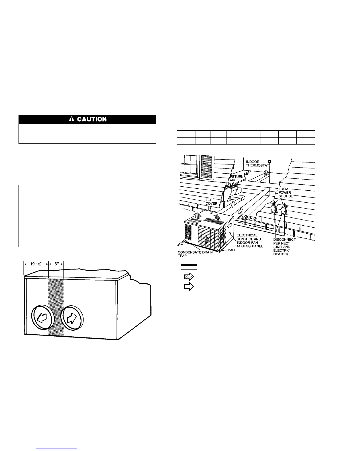
When connecting ductwork to units, do not drill deeper
than1⁄2inch in shaded area in Fig. 10 or coil may be
damaged.
• All units should have field-supplied filters or accessory fil-
ter rack installed in the return-air side of the unit. Recommended sizes for filters are shown in Table 1.
• Avoid abrupt duct size increases and reductions. Abrupt
change in duct size adversely affects air performance.
IMPORTANT: Use flexible connectors between
ductwork and unit to prevent transmission of vibration. Use suitable gaskets to ensure weathertight and
airtight seal. When electric heat is installed, use fireproof canvas (or similar heat resistant material) connector between ductwork and unit discharge connection. If flexible duct is used, insert a sheet metal sleeve
inside duct. Heat resistant duct connector (or sheet metal
sleeve) must extend 24-in. from electric heater
element.
• Size ductwork for cooling air quantity (cfm). The minimum air quantity for proper electric heater operation is
listed in Table 2. Heater limit switches may trip at air quantities below those recommended.
• Insulate and weatherproof all external ductwork. Insulate
and cover with a vapor barrier all ductwork passing through
conditioned spaces. Follow latest Sheet Metal andAir Conditioning Contractors NationalAssociation (SMACNA) and
Air Conditioning Contractors Association (ACCA) minimum installation standards for residential heating and air
conditioning systems.
• Secure all ducts to building structure. Flash, weatherproof, and vibration-isolate duct openings in wall or roof
according to good construction practices.
Figure 11 shows a typical duct system with 50HS
installed.
Table 2 — Minimum Airflow for
Safe Electric Heater Operation
SIZE 018 024 030 036 042 048 060
CFM 700 700 875 1200 1225 1400 1750
NOTE: Do not drill more than1⁄2-in. deep into shaded area.
Fig. 10 — Area Not To Be Drilled
Power Wiring
Control Wiring
Outdoor Airflow
Indoor Airflow
*Separate disconnect per NEC
(NationalElectricCode)required
for electric heater when singlepoint connection is not used.
Fig. 11 — Typical Installation
10
Page 11
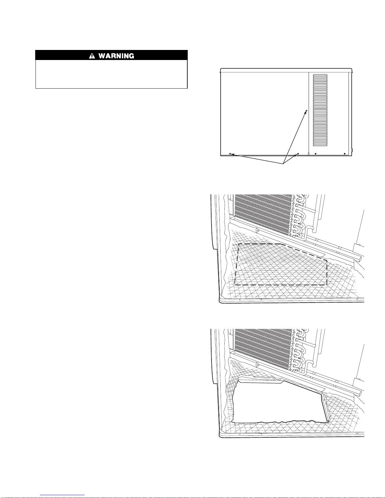
CONVERTING HORIZONTAL DISCHARGE UNITS TO
DOWNFLOW (VERTICAL) DISCHARGE — The 50HS
units are shipped in a horizontal configuration. To convert a
horizontal unit for downflow (vertical) discharge, perform
the following steps:
Before performing service or maintenance operations on
system, turn off main power to unit. Turn off accessory
heater power switch if applicable. Electrical shock can
cause personal injury.
1. Open all electrical disconnects before starting any service work.
2. Remove indoor coil access panel (Fig. 12). Save screws.
3. Locate lances in basepan insulation that are placed over
the perimeter of the vertical duct opening cover
(Fig. 13).
4. Using a straight edge and sharp knife, cut and remove
the insulation around the perimeter of the cover. Remove the screws securing the cover to the basepan and
slide out the cover. Discard the cover (Fig. 14).
5. Removeindoor blower access panel (Fig. 15). Save screws.
6. Disconnect indoor-fan motor leads from indoor-fan
relay and unit contactor (Fig. 16). Carefully disengage
wire tie containing indoor-fan motor leads from the unit
control box.
7. Remove screws (Fig. 17) securing indoor blower housing to blower shelf and carefully slide out blower housing. On sizes 018-042 there is a filler bracket attached
to the blower shelf; remove this filler bracket and retain
for later use.
8. Locate lances in basepan insulation that are placed over
the perimeter of the vertical discharge opening cover
(Fig. 18).
9. Using a straight edge and sharp knife, cut the insulation
around the perimeter of the cover. Remove the screws
securing the cover to the basepan and slide out the cover
(Fig. 19). Discard the cover. Install filler bracket removed in Step 7, if any.
10. If unit ductwork is to be attached to vertical opening
flanges on the unit basepan (jackstand applications only),
do so at this time.
11. It is recommended that the basepan insulation around
the perimeter of the vertical opening be secured to the
basepan with aluminum tape to prevent the insulation
from tearing or bunching up when the blower housing is
installed in the vertical discharge position.
12. Orient blower housing for vertical airflow (blower motor adjacent to horizontal duct opening) and slide into
vertical opening making sure the flanges on the blower
side plates engage the tabs in the unit basepan.
Resistance will be felt as the blower housing contacts
the basepan insulation; this can be overcome by applying a slight force to the base of the blower. Continue
sliding blower in until hole in side plate flange aligns
with the hole in the basepan.
Secure using screws removed in Step 7. Reconnect indoorfan motor leads and insert wire tie back into unit control
box (Fig. 16).
13. Cover the horizontal duct openings. Duct covers can be
ordered as an accessory or be field-fabricated as shown
in Fig. 20.
14. Reinstall the indoor coil and indoor blower access
panels.
15. Aftercompleting unit installation, perform all safety checks
and power up unit.
ACCESS PANEL
SCREWS
Fig. 12 — Indoor Coil Access Panel
Fig. 13 — Basepan Insulation Over
Vertical Duct Opening
Fig. 14 — Insulation and Cover Removed
from Vertical Duct Opening
11
Page 12
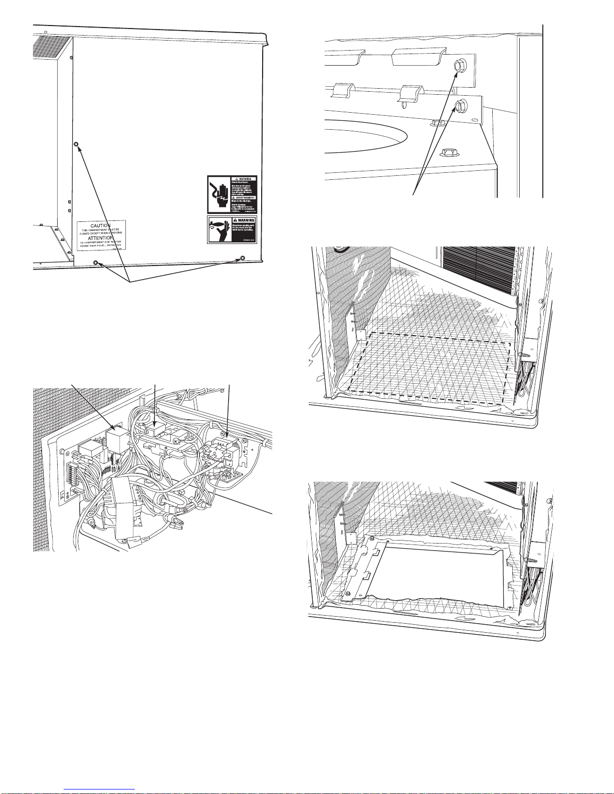
INDOOR BLOWER ACCESS PANEL SCREWS
Fig. 15 — Indoor Blower Access Panel
DEFROST
BOARD CONTACTOR RELAY
Fig. 16 — Fan Motor Leads
REMOVE
Fig. 17 — Blower Shelf and Housing
Fig. 18 — Basepan Insulation Over
Vertical Discharge Opening
Fig. 19 — Insulation and Cover Removed
from Vertical Discharge Opening
12
Page 13
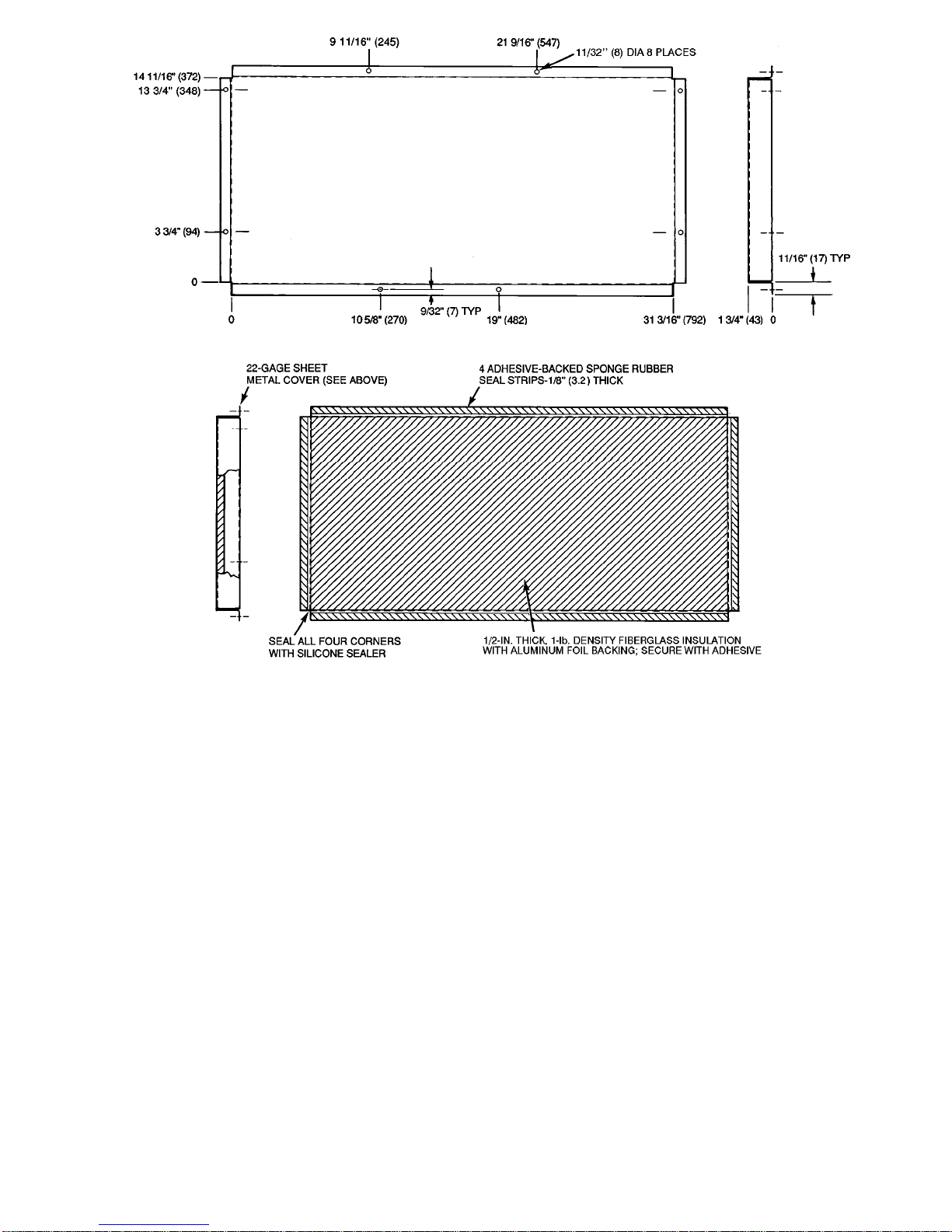
NOTES:
1. An accessory duct cover is available as an alternative to field fabrication.
2. Construct duct cover out of 22-gage sheet metal.
3. Dimensions in ( ) are in millimeters.
Fig. 20 — Field-Fabricated Duct Cover
13
Page 14
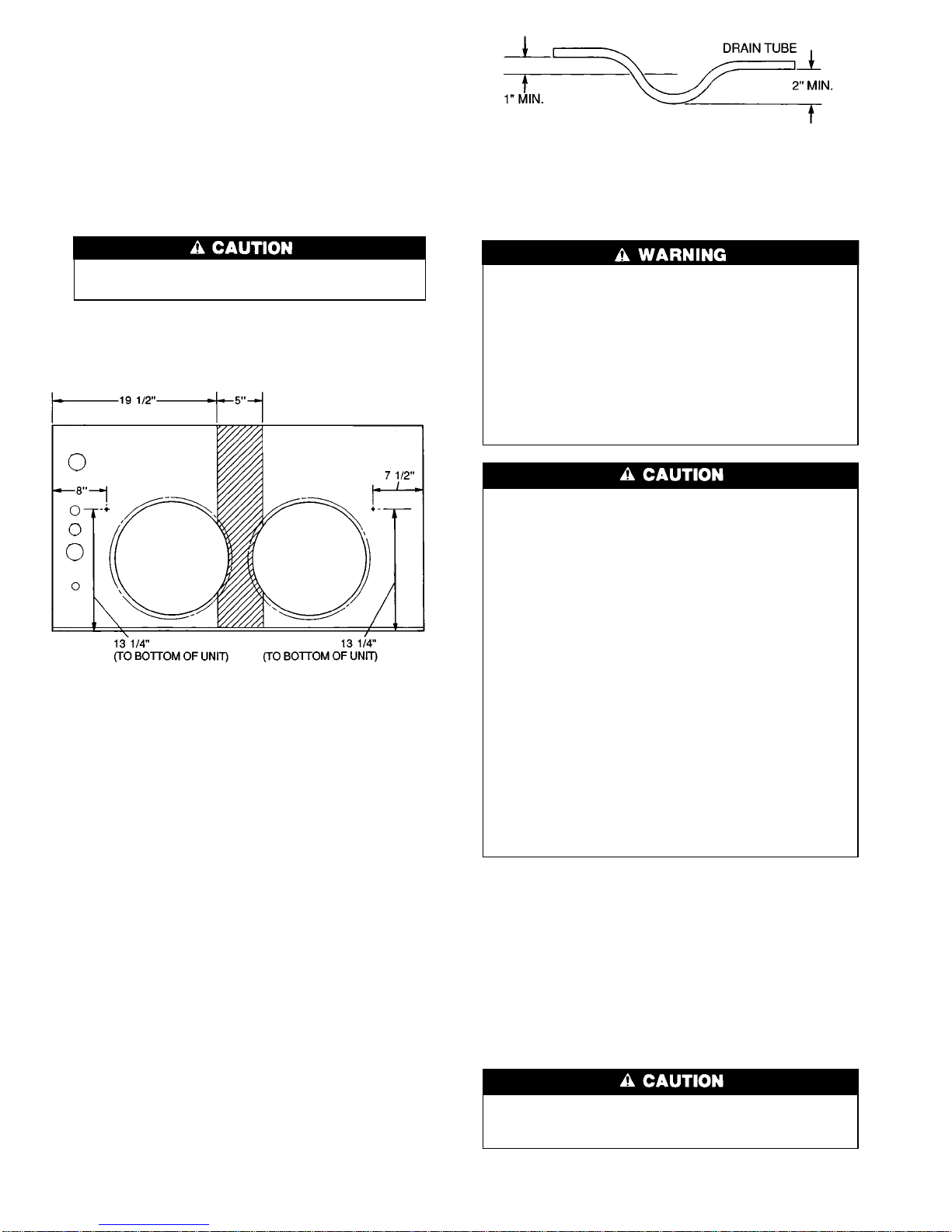
ACCESSORY DUCT FLANGE KIT INSTALLATION —
Refer to Fig. 21 for duct adapter dimensions and hole
locations.
1. Mark hole locations shown in Fig. 21.
2. At marked locations, drill holes using a no. 26
(.147-in.) twist drill.
3. Partially secure duct flanges using two of the no. 10,
1
⁄2-in. screws provided.
4. See the following caution. Using remaining holes in duct
flanges as templates, drill the remaining holes with the
no. 26 (.147-in.) drill.
Do not drill deeper than1⁄2-in. into shaded area shown
in Fig. 21. Damage to refrigerant coil could result.
5. Fully secure the duct flanges using the remaining screws
provided.
The finished kit installation accommodates a 14
3
⁄4-in. x
143⁄4-in. duct.
Step 6 — Provide for Condensate Disposal
NOTE: Be sure that condensate-water disposal methods comply with local codes, restrictions, and practices.
The 50HS units dispose of condensate through a
3
⁄4in.
NPT fitting which exits through the compressor access panel.
See Fig. 2-5 for location of condensate connection.
Condensate water can be drained directly onto the roof in
rooftop installations (where permitted) or onto a gravel apron
in ground-level installations. Install a field-supplied condensate trap at end of condensate connection to ensure proper
drainage. See Fig. 22. Make sure that the outlet of the trap
is at least 1 in. lower than the drain-pan condensate connection to prevent the pan from overflowing. Prime the trap
with water. When using a gravel apron, make sure it slopes
away from the unit.
If the installation requires draining the condensate water
away from the unit, install a 2-in. trap using a
3
⁄4-in. FPT
connection. See Fig. 22. Make sure that the outlet of the trap
is at least 1 in. lower than the unit drain-pan condensate connection to prevent the pan from overflowing.
Prime the trap with water. Connect a drain tube using a
minimum of
3
⁄4-in. PVC,3⁄4-in. CPVC, or3⁄4-in. copper pipe
(all field supplied). Do not undersize the tube. Pitch the drain
tube downward at a slope of at least 1 in. for every 10 ft of
horizontal run. Be sure to check the drain tube for leaks.
Step 7 — Install Electrical Connections
The unit cabinet must have an uninterrupted, unbroken
electrical ground to minimize the possibility of personal
injury if an electrical fault should occur. This ground
may consist of an electrical wire connected to the unit
ground lug in the control compartment, or conduit approved for electrical ground when installed in accordance with NEC (National Electrical Code), ANSI
(American National Standards Institute)/NFPA (latest edition) (in Canada, Canadian Electrical Code CSA C22.1)
and local electrical codes. Failure to adhere to this warning could result in personal injury or death.
Failure to follow these precautions could result in damage to the unit being installed:
1. Make all electrical connections in accordance with
NEC ANSI/NFPA (latest edition) and local electrical codes governing such wiring. In Canada, all electrical connections must be in accordance with CSA
(Canadian Standards Association) Standard C22.1 Canadian Electrical Code Part 1 and applicable local
codes. Refer to unit wiring diagram.
2. Use only copper conductor for connections between
field-supplied electrical disconnect switch and unit.
DO NOT USE ALUMINUM WIRE.
3. Be sure that high-voltage power to unit is within operating voltage range indicated on unit rating plate.
On 3-phase units, ensure that phases are balancedwithin
2%. Consult local power company for correction of
improper voltage and/or phase imbalance.
4. Insulate low-voltage wires for highest voltage contained within conduit when low-voltage control wires
are run in same conduit as high-voltage wires.
5. Do not damage internal components when drilling
through any panel to mount electrical hardware, conduit, etc.
HIGH-VOLTAGE CONNECTIONS — The unit must have
a separate electrical service with a field-supplied, waterproof disconnect switch mounted at, or within sight from the
unit. Refer to the unit rating plate for maximum fuse/circuit
breaker size and minimum circuit amps (ampacity) for wire
sizing. See Table 3 for electrical data.
The field-supplied disconnect may be mounted on the unit
over the high-voltage inlet hole. See Fig. 2-5.
If the unit has an electric heater, a second disconnect may
be required. Consult the Installation, Start-Up and Service
Instructions provided with the accessory for electrical service connections.
Operation of unit on improper line voltage constitutes
abuse and may cause unit damage that could affect
warranty.
Fig. 22 — Drain Tubing Connection and
Condensate Trap
NOTE: Do not drill more than1⁄2-in. deep in shaded area.
Fig. 21 — Duct Flange Kit — Locating Holes
14
Page 15
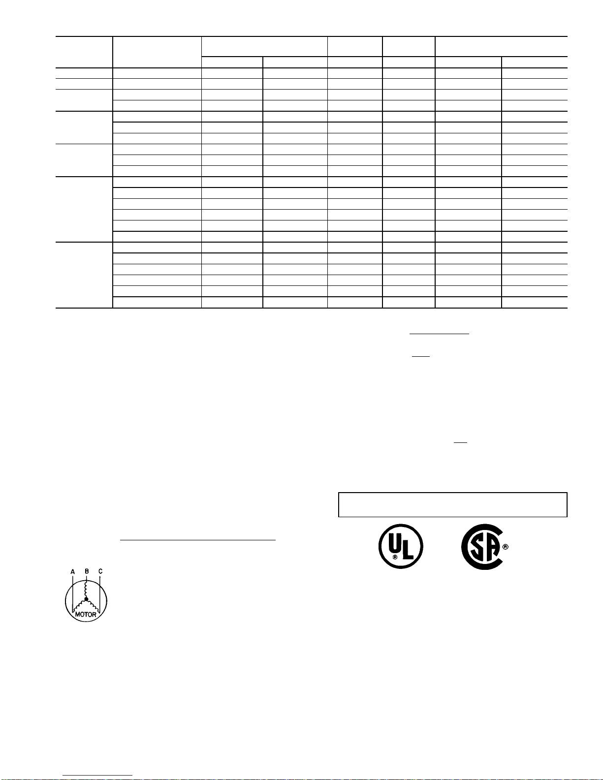
Table 3 — Electrical Data
UNIT
SIZE
50HS
V-Ph-Hz
COMPRESSOR OFM IFM
POWER SUPPLY
MOCP
RLA LRA FLA FLA MCA MAX
018 208/230-1-60 10.4 49.0 0.7 1.8 15.5 25
024 208/230-1-60 11.2 61.0 1.4 2.0 17.4 25
030
208/230-1-60 14.4 82.0 1.4 2.6 22.0 30
208/230-3-60 10.4 65.5 1.4 2.6 17.0 25
036
208/230-1-60 18.0 96.0 1.4 2.8 26.7 40
208/230-3-60 11.4 75.0 1.4 2.8 18.5 25
460-3-60 4.8 40.0 0.8 1.4 9.0 10
042
208/230-1-60 20.4 102.0 1.4 4.0 30.9 50
208/230-3-60 14.0 91.0 1.4 4.0 22.9 30
460-3-60 6.4 42.0 0.8 2.0 10.8 15
048
208/230-1-60* 24.4 140.0 2.1 5.0 40.1 60
208/230-1-60† 26.4 129.0 2.1 5.0 40.1 60
208/230-3-60* 14.1 105.0 2.1 5.0 25.9 35
208/230-3-60† 15.0 99.0 2.1 5.0 25.9 40
460-3-60* 7.1 55.0 1.1 2.3 13.7 15
460-3-60† 8.2 49.5 1.1 2.3 13.7 20
060
208/230-1-60* 28.9 165.0 2.1 6.2 48.4 60
208/230-1-60† 32.1 169.0 2.1 6.2 48.4 60
208/230-3-60* 16.0 125.0 2.1 6.2 32.4 40
208/230-3-60† 19.3 123.0 2.1 6.2 32.4 50
460-3-60* 8.0 66.0 1.1 3.2 16.8 20
460-3-60† 10.0 62.0 1.1 3.2 16.8 25
LEGEND
CSA — Canadian Standards Association
FLA — Full Load Amps
HACR — Heating, Air Conditioning and Refrigeration
IFM — Indoor-Fan Motor
LRA — Locked Rotor Amps
MCA — Minimum Circuit Amps
MOCP — Maximum Overcurrent Protection
(fuses or HACR-type circuit breaker)
NEC — National Electrical Code
OFM — Outdoor-Fan Motor
RLA — Rated Load Amps
*Carrier Scroll Compressor.
†Copeland Scroll Compressor.
NOTES:
1. In compliance with NEC requirements for multimotor and combinationloadequipment(refertoNECArticles 430 and 440), the overcurrentprotectivedevicefortheunitshallbefuseorHACRbreaker.
The CSA units may be fuse or circuit breaker.
2. Unbalanced 3-Phase Supply Voltage
Never operate a motor where a phase imbalance in supply voltage
is greater than 2%.
Use the following formula to determine the per-
cent of voltage imbalance.
% Voltage Imbalance
max voltage deviation from average voltage
= 100 x
average voltage
Example: Supply voltage is 460-3-60.
AB = 452 v
BC = 464 v
AC = 455 v
452 + 464 + 455
Average Voltage =
3
1371
=
3
= 457
Determine maximum deviation from average voltage.
(AB) 457 – 452 = 5 v
(BC) 464 – 457 = 7 v
(AC) 457 – 455 = 2 v
Maximum deviation is 7 v.
Determine percent of voltage imbalance.
7
% Voltage Imbalance = 100 x
457
= 1.53%
This amount of phase imbalance is satisfactory as it is below the
maximum allowable 2%.
IMPORTANT: If the supply voltage phase imbalance is more
than 2%, contact your local electric utility company immediately.
15
Page 16
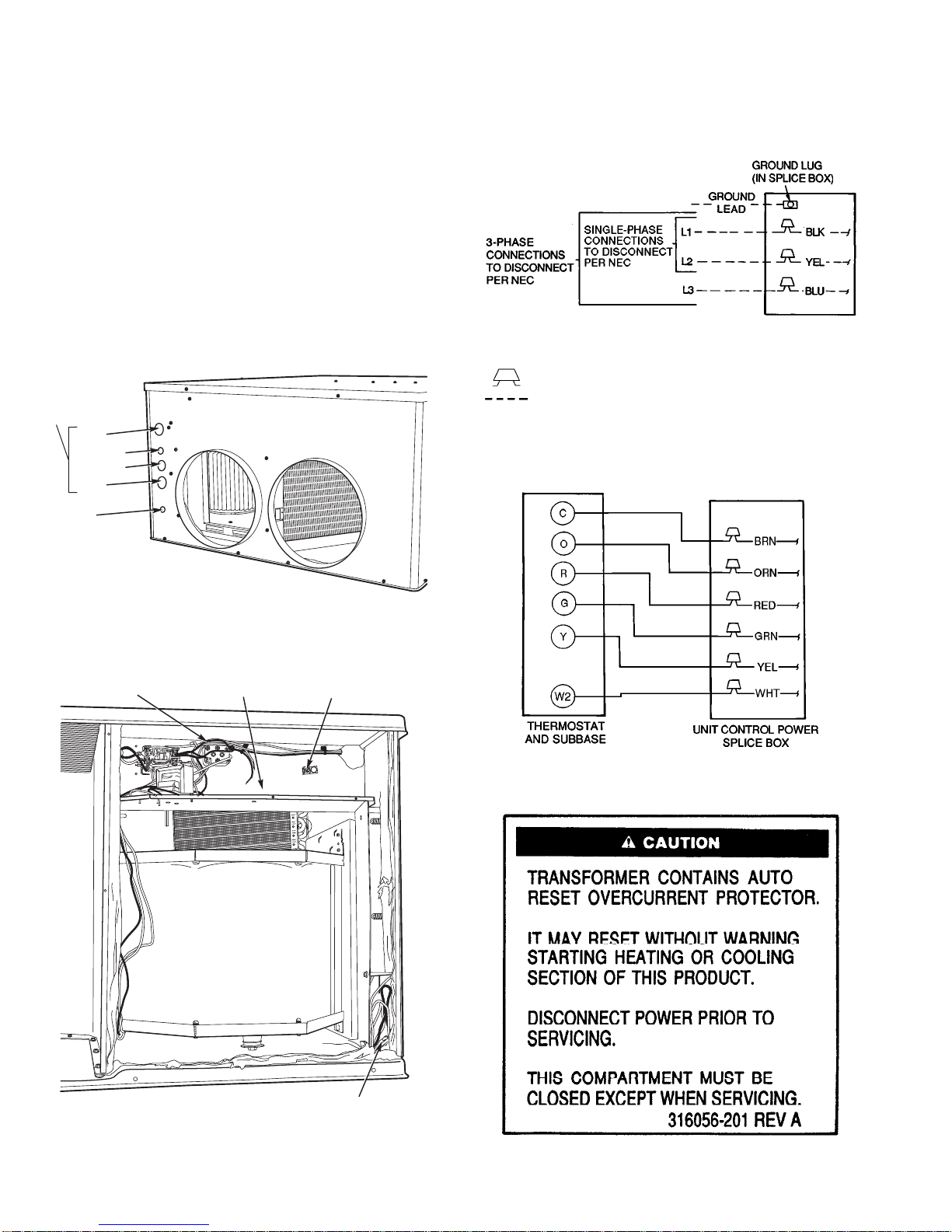
ROUTING POWER LEADS INTO UNIT — Use only copper wire between disconnect and unit. The high-voltage leads
should be in a conduit until they enter the duct panel; conduit termination at the duct panel must be watertight. Run
the high-voltage leads through the knockout on the duct panel
(see Fig. 23 for location and size). When the leads are inside
the unit, run leads up the high-voltage raceway to the line
wiring splice box (Fig. 24). For single-phase units, connect
leads to the black and yellow wires; for 3-phase units, connect the leads to the black, yellow, and blue wires (see
Fig. 25).
CONNECTING GROUND LEAD TO GROUND LUG —
Refer to Fig. 24 and 25. Connect the ground lead to the chassis using the ground lug in the wiring splice box.
ROUTING CONTROL POWER WIRES (24 v) — Form a
drip-loop with the thermostat leads before routing them into
the unit. Route the thermostat leads through grommeted hole
provided in unit into unit control power splice box. See
Fig. 23. Connect thermostat leads to unit control power leads
as shown in Fig. 26.
The unit transformer supplies 24-v power for complete
system including accessory electrical heater. An automaticreset circuit breaker is provided in the 24-v circuit; see the
caution label on the transformer or Fig. 27. Transformer
is factory wired for 230-v operation. If supply voltage is
208 v, rewire transformer primary as described in the
following section.
1 3/8″ DIA.
1 1/8″ DIA.
POWER
ENTRY
2″ DIA.
2″ DIA.
7/8″ DIA.
LOW VOLTAGE
ENTRY
NOTE: Knockout sizes are for round-duct units. For rectangular duct
unit dimensions, see Fig. 4 and 5.
Fig. 23 — Duct Panel Knockouts
UNIT LINE WIRE
SPLICE BOX
UNIT POWER
LEAD
CONTROL POWER
SPLICE BOX
GROUND
LUG
Fig. 24 — Wiring Splice Boxes
LEGEND
NEC — National Electrical Code
Splice Connections
Field Wiring
NOTE: Use copper wire only.
Fig. 25 — Line Power Connections
Fig. 26 — Control Connections
Fig. 27 — Transformer Label
16
Page 17
SPECIAL PROCEDURES FOR 208-V OPERATION
Make sure that the power supply to the unit is switched
OFF before making any wiring changes. Electrical shock
can cause personal injury or death.
1. Disconnect the orange transformer-primary lead from the
contactor. See unit wiring label.
2. Remove the wirenut from the terminal on the end of the
red transformer-primary lead.
3. Save the wirenut.
4. Connect the red lead to the contactor terminal from which
the orange lead was disconnected.
5. Using the wirenut removed from the red lead, insulate
the loose terminal on the orange lead.
6. Wrap the wirenut with electrical tape so that the metal
terminal cannot be seen.
Indoor blower-motor speeds may need to be changed for
208-v operation. Refer to Indoor Airflow and Airflow Adjustments section on page 22.
PRE-START-UP
Failure to observe the following warnings could result
in serious personal injury:
1. Follow recognized safety practices and wear protective goggles when checking or servicing refrigerant
system.
2. Do not operate compressor or provide any electric
power to unit unless compressor terminal cover is in
place and secured.
3. Do not remove compressor terminal cover until all
electrical sources are disconnected.
4. Relieve all pressure from both high- and lowpressure sides of the system before touching or disturbing anything inside terminal box if refrigerant leak
is suspected around compressor terminals. Use accepted methods to recover refrigerant.
5. Never attempt to repair soldered connection while refrigerant system is under pressure.
6. Do not use torch to remove any component. System
contains oil and refrigerant under pressure. To remove a component, wear protective goggles and proceed as follows:
a. Shut off electrical power to unit.
b. Relieve all pressure from system using both high-
and low-pressure ports. Use accepted methods to
recover refrigerant.
c. Cut component connecting tubing with tubing cut-
ter and remove component from unit.
d. Carefully unsweat remaining tubing stubs when
necessary. Oil can ignite when exposed to torch
flame.
Use the Start-Up Checklist supplied at the end of this book
and proceed as follows to inspect and prepare the unit for
initial start-up:
1. Remove all access panels.
2. Read and follow instructions on all WARNING, CAU-
TION, and INFORMATION labels attached to, or shipped
with, unit.
Make the following inspections:
a. Inspect for shipping and handling damages such as bro-
ken lines, loose parts, disconnected wires, etc.
b. Inspect for oil at all refrigerant tubing connections and
on unit base. Detecting oil generally indicates a refrigerant leak. Leak-test all refrigerant tubing connections using electronic leak detector, or liquid-soap solution. If a refrigerant leak is detected, see Check for
Refrigerant Leaks section, page 18.
c. Inspect all field- and factory-wiring connections. Be
sure that connections are completed and tight.
d. Inspect coil fins. If damaged during shipping and han-
dling, carefully straighten fins with a fin comb.
3. Verify the following conditions:
a. Make sure that outdoor-fan blade is correctly posi-
tioned in fan orifice. Leading edge of blade should be
2 in. back from condenser inlet grille.
b. Make sure that air filter(s) is in place.
c. Make sure that condensate drain pan and trap are filled
with water to ensure proper drainage.
d. Make sure that all tools and miscellaneous loose parts
have been removed.
4. If the unit is equipped with a crankcase heater, start the
heater 24 hours before starting the unit. To start the heater
only, turn the thermostat to the OFF position and energize the electrical disconnect to the unit.
17
Page 18
START-UP
Use the Start-Up Checklist supplied at the end of this book,
and proceed as follows:
Check for Refrigerant Leaks — Locate and repair
refrigerant leaks and charge the unit as follows:
1. Using both high- and low-pressure ports, locate leaks and
reclaim remaining refrigerant to relieve system pressure.
2. Repair leak following accepted practices.
NOTE: Install a filter drier whenever the system has been
opened for repair.
3. Check system for leaks using an approved method.
4. Evacuate refrigerant system and reclaim refrigerant if no
additional leaks are found.
5. Charge unit with R-22 refrigerant, using a volumetriccharging cylinder or accurate scale. Refer to unit rating
plate for requiredcharge. Be sure to add extra refrigerant
to compensate for internal volume of filter drier.
Unit Start-Up Adjustments
Complete the required procedures given in the PreStart-Up section page 17 before starting the unit.
Do not jumper any safety devices when operating the
unit.
Do not operate the unit in Cooling mode when the
outdoor temperature is below 40 F (unless accessory lowambient kit is installed).
Do not rapid-cycle the compressor. Allow 5 minutes
between ‘‘on’’ cycles to prevent compressor damage.
CHECKING COOLING AND HEATING CONTROL OPERATION — Start and check the unit for proper control operation as follows:
1. Place room thermostat SYSTEM switch in OFF position.
Observe that blower motor starts when FANswitch is placed
in ON position and shuts down within 30 seconds when
FAN switch is placed in AUTO. position.
2. Place SYSTEM switch in COOLposition and F ANswitch
in AUTO. position. Set control below room temperature.
Observe that compressor, outdoor fan, and indoor blower
motors start. Observe that cooling cycle shuts down when
control setting is satisfied.
3. Place system switch in HEAT position. Set control above
room temperature. Observe that heating cycle shuts down
when control setting is satisfied.
4. When using an automatic changeover room thermostat,
place both SYSTEM and FAN switches in AUTO. positions. Observe that unit operates in Cooling mode when
temperature control is set to ‘‘call for Cooling’’ (below
room temperature), and unit operates in Heating mode
when temperature control is set to ‘‘callfor heating’’(above
room temperature).
IMPORTANT: Scroll compressors in the 048 and
060 size units are direction-oriented. Three-phase
units must be checked to ensure proper compressor
3-phase power lead orientation. If not corrected within
5 minutes, the internal protector will shut off the
compressor.The 3-phase power leads to the unit must
be reversed to correct rotation. When turning backwards, scroll compressors emit elevated noise levels, and the difference between compressor suction
and discharge pressures may be dramatically lower
than normal.
CHECKINGANDADJUSTING REFRIGERANT CHARGE
— The refrigerant system is fully charged with R-22 refrigerant, and is tested and factory sealed.
NOTE: Adjustment of the refrigerant charge is not required
unless the unit is suspected of not having the proper R-22
charge. The charging label and the tables shown refer to system temperatures and pressures in Cooling mode only.If charge
level is suspect in Heating mode, reclaim all refrigerant and
charge to nameplate amount.
A superheat charging label is attached to the inside of the
compressor access door.Thelabel includes a ‘ ‘SuperheatCharging Table’’ and a ‘‘Required Suction-Tube Temperature (F)’’
chart.
An accurate superheat, thermocouple-, or thermistor-type
thermometer, a sling psychrometer, and a gage manifold are
required when using the superheat charging method for evaluating the unit charge. Do not use mercury or small dial-type
thermometers because they are not adequate for this type of
measurement.
When evaluating the refrigerant charge, an indicated adjustment to the specified factory charge must always be
very minimal. If a substantial adjustment is indicated,
an abnormal condition exists somewhere in the cooling
system, such as insufficient airflow across either coil or
both coils.
Proceed as follows:
1. Remove caps from low- and high-pressure service
fittings.
2. Using hoses with valve core depressors, attach low- and
high-pressure gage hoses to low- and high-pressure service fittings, respectively.
3. Start unit in Cooling mode and let unit run until system
pressures stabilize.
4. Measure and record the following:
a. Outdoor ambient-air temperature (F db).
b. Indoor inlet-air temperature (F wb).
c. Suction-tube temperature (F) at low-side service
fitting.
d. Suction (low-side) pressure (psig).
5. UsingSuperheat Charging Tables4A-4G,compare outdoor-
air temperature (F db) with indoor-air temperature (F wb)
to determine desired system operating superheat
temperature.
6. Using Required Suction-Tube Temperature (F) Table 5,
compare desired superheat temperature with suction (lowside) operating pressure (psig) to determine proper suctiontube temperature.
7. Compare actual suction-tube temperature with proper
suction-tube temperature. Using a tolerance of ±3° F, add
refrigerant if actual temperature is more than 3° F higher
than proper suction-tube temperature, or remove refrigerant if actual temperature is more than 3° F lower than
required suction-tube temperature.
NOTE: If the problem causing the inaccurate readings is a
refrigerant leak, refer to Check for Refrigerant Leaks section on this page.
18
Page 19
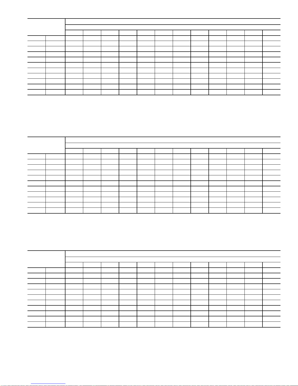
Table 4A — Superheat Charging Table, 50HS018
TEMP (F)
OUTDOOR
AIR
INDOOR AIR — 675 CFM
Indoor Air — Ewb (F)
54 56 58 60 62 64 66 68 70 72 74 76
65 SPH 39.9 39.9 40.0 40.0 42.7 45.4 48.1 48.3 48.5 48.8 48.6 48.4
70 SPH 34.9 34.9 34.9 35.0 38.3 41.6 45.0 45.6 46.1 46.7 46.6 46.4
75 SPH 29.9 29.9 29.9 29.9 33.9 37.9 41.9 42.8 43.7 44.7 44.5 44.4
80 SPH 26.3 26.3 26.3 26.3 30.3 34.3 38.3 39.8 41.2 42.6 42.7 42.9
85 SPH 22.8 22.8 22.8 22.8 26.8 30.8 34.8 36.7 38.6 40.6 41.0 41.3
90 SPH 20.8 20.8 20.8 20.8 24.2 27.7 31.3 34.0 36.7 39.4 39.6 39.8
95 SPH 18.7 18.7 18.7 18.7 21.7 24.7 27.7 31.2 34.7 38.2 38.2 38.3
100 SPH 16.6 16.6 16.6 16.6 19.1 21.6 24.1 28.1 32.1 36.1 36.5 36.9
105 SPH 14.6 14.6 14.6 14.6 16.6 18.6 20.6 25.1 29.6 34.1 34.8 35.6
110 SPH 12.5 12.5 12.5 12.5 14.0 15.5 17.0 21.5 26.0 30.5 32.8 35.0
115 SPH 10.5 10.5 10.5 10.5 11.5 12.5 13.5 18.0 22.5 27.0 30.7 34.5
LEGEND
Ewb — Entering Wet Bulb
SPH — Superheat at Compressor (F)
Table 4B — Superheat Charging Table, 50HS024
TEMP (F)
OUTDOOR
AIR
INDOOR AIR — 800 CFM
Indoor Air — Ewb (F)
54 56 58 60 62 64 66 68 70 72 74 76
65 SPH 18.7 19.5 20.3 21.2 24.6 28.1 31.5 33.3 35.0 36.8 37.1 37.4
70 SPH 14.6 15.4 16.3 17.1 20.7 24.3 28.0 30.2 32.5 34.7 35.2 35.8
75 SPH 10.5 11.4 12.2 13.0 16.8 20.6 24.4 27.2 29.9 32.7 33.4 34.1
80 SPH 9.4 9.9 10.3 10.7 14.6 18.5 22.3 25.1 27.9 30.6 31.9 33.1
85 SPH * * 8.4 8.4 12.4 16.3 20.3 23.1 25.8 28.6 30.3 32.1
90 SPH * * * 5.9 10.0 14.1 18.3 21.0 23.8 26.5 28.8 31.0
95 SPH ****7.611.916.2 19.0 21.7 24.5 27.2 30.0
100 SPH ****6.210.2 14.1 17.4 20.7 23.9 26.4 29.0
105 SPH *****8.512.1 15.9 19.6 23.4 25.6 27.9
110 SPH *****6.28.612.8 17.1 21.3 24.1 26.9
115 SPH *******9.814.5 19.3 22.6 25.8
LEGEND
Ewb — Entering Wet Bulb
SPH — Superheat at Compressor (F)
*Do not attempt to charge system under these conditions — refrig-
erant slugging may occur.
Table 4C — Superheat Charging Table, 50HS030
TEMP (F)
OUTDOOR
AIR
INDOOR AIR — 1000 CFM
Indoor Air — Ewb (F)
54 56 58 60 62 64 66 68 70 72 74 76
65 SPH 21.0 21.0 21.0 21.0 24.1 27.2 30.3 31.0 31.8 32.5 32.0 31.5
70 SPH 16.5 16.5 16.5 16.5 20.4 24.3 28.2 29.0 29.7 30.5 30.3 30.2
75 SPH 12.0 12.0 12.0 12.0 16.7 21.5 26.2 26.9 27.7 28.4 28.7 29.0
80 SPH 10.5 10.5 10.5 10.5 14.5 18.6 22.6 23.9 25.1 26.3 26.7 27.1
85 SPH 9.0 9.0 9.0 9.0 12.4 15.7 19.1 20.8 22.6 24.3 24.8 25.2
90 SPH ****8.211.915.5 17.8 20.0 22.3 23.1 24.0
95 SPH *****8.012.0 14.7 17.5 20.2 21.5 22.8
100 SPH *****6.69.912.7 15.4 18.1 19.9 21.6
105 SPH ******7.910.6 13.4 16.1 18.3 20.4
110 SPH *******7.610.8 14.0 16.6 19.2
115 SPH ********8.312.0 15.0 18.0
LEGEND
Ewb — Entering Wet Bulb
SPH — Superheat at Compressor (F)
*Do not attempt to charge system under these conditions — refrig-
erant slugging may occur.
19
Page 20
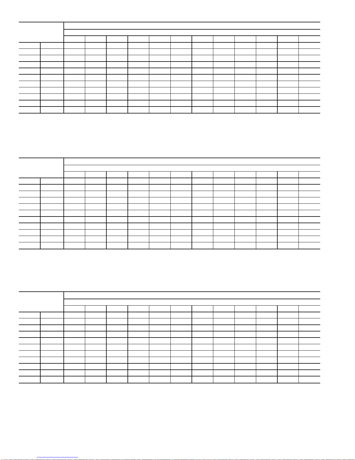
Table 4D — Superheat Charging Table, 50HS036
TEMP (F)
OUTDOOR
AIR
INDOOR AIR — 1300 CFM
Indoor Air — Ewb (F)
54 56 58 60 62 64 66 68 70 72 74 76
65 SPH 16.7 18.7 20.7 22.7 27.4 32.1 36.8 37.7 38.6 39.5 39.6 39.8
70 SPH 12.9 13.8 14.8 15.9 22.1 28.4 34.8 35.6 36.5 37.4 37.6 37.8
75 SPH 9.0 9.0 9.0 9.0 16.9 24.8 32.7 33.6 34.5 35.4 35.5 35.7
80 SPH ****12.7 20.9 29.1 31.1 33.0 35.0 35.1 35.1
85 SPH ****8.517.1 25.6 28.6 31.6 34.6 34.6 34.6
90 SPH ****7.414.7 22.0 25.5 29.0 32.5 33.3 34.0
95 SPH ****6.212.3 18.5 22.5 26.5 30.5 32.0 33.5
100 SPH ****5.010.0 14.9 19.4 23.9 28.5 30.0 31.5
105 SPH *****7.611.416.4 21.4 26.4 27.9 29.4
110 SPH *****5.57.912.8 17.8 22.8 25.1 27.3
115 SPH *******9.314.3 19.3 22.3 25.3
LEGEND
Ewb — Entering Wet Bulb
SPH — Superheat at Compressor (F)
*Do not attempt to charge system under these conditions — refrig-
erant slugging may occur.
Table 4E — Superheat Charging Table, 50HS042
TEMP (F)
OUTDOOR
AIR
INDOOR AIR — 1400 CFM
Indoor Air — Ewb (F)
54 56 58 60 62 64 66 68 70 72 74 76
65 SPH 9.0 11.0 13.0 15.0 19.5 24.0 28.5 30.5 32.5 34.5 34.9 35.3
70 SPH * 5.5 6.5 7.5 13.8 20.1 26.5 28.4 30.4 32.4 33.1 33.7
75 SPH ****8.116.3 24.4 26.4 28.4 30.4 31.3 32.2
80 SPH ****7.514.9 22.3 24.8 27.3 29.8 30.3 30.7
85 SPH ****6.813.5 20.3 23.3 26.3 29.3 29.2 29.2
90 SPH ****6.112.2 18.3 21.2 24.2 27.3 27.4 27.6
95 SPH ****5.410.8 16.2 19.2 22.2 25.2 25.6 26.1
100 SPH ****5.210.4 15.6 18.6 21.6 24.6 25.4 26.1
105 SPH ****5.010.1 15.1 18.1 21.1 24.1 25.1 26.0
110 SPH *****8.713.0 16.0 19.0 22.0 24.0 26.0
115 SPH *****7.311.014.0 17.0 20.0 23.0 26.0
LEGEND
Ewb — Entering Wet Bulb
SPH — Superheat at Compressor (F)
*Do not attempt to charge system under these conditions — refrig-
erant slugging may occur.
Table 4F — Superheat Charging Table, 50HS048
TEMP (F)
OUTDOOR
AIR
INDOOR AIR — 1600 CFM
Indoor Air — Ewb (F)
54 56 58 60 62 64 66 68 70 72 74 76
65 SPH 25.8 26.3 27.0 27.6 28.6 29.6 30.5 30.9 31.3 31.7 31.2 30.7
70 SPH 24.2 24.0 23.8 23.6 25.0 26.4 27.8 28.4 29.0 29.7 29.6 29.5
75 SPH 19.7 19.7 19.7 19.7 21.4 23.2 25.0 25.9 26.8 27.6 27.9 28.2
80 SPH 15.8 15.8 15.8 15.8 17.6 19.4 21.2 22.7 24.1 25.6 26.2 26.9
85 SPH 12.0 12.0 12.0 12.0 13.8 15.6 17.5 19.5 21.5 23.5 24.5 25.6
90 SPH 7.5 7.5 7.5 7.5 9.4 11.3 13.2 16.3 19.3 22.4 23.3 24.2
95 SPH ****5.07.09.013.1 17.1 21.2 22.0 22.8
100 SPH *******9.414.3 19.1 20.3 21.4
105 SPH *******5.711.417.1 18.6 20.1
110 SPH ********9.013.5 15.8 18.0
115 SPH ********6.710.0 13.0 16.0
LEGEND
Ewb — Entering Wet Bulb
SPH — Superheat at Compressor (F)
*Do not attempt to charge system under these conditions — refrig-
erant slugging may occur.
20
Page 21
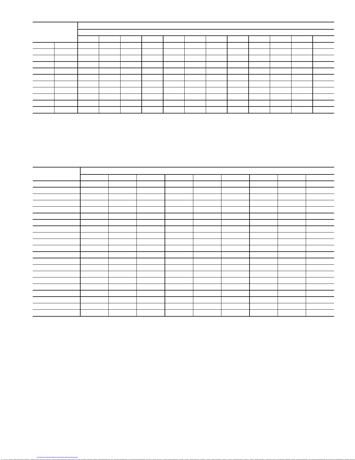
Table 4G — Superheat Charging Table, 50HS060
TEMP (F)
OUTDOOR
AIR
INDOOR AIR — 2000 CFM
Indoor Air — Ewb (F)
54 56 58 60 62 64 66 68 70 72 74 76
65 SPH 24.8 24.8 24.8 24.8 25.6 26.4 27.2 28.0 28.8 29.6 29.0 28.5
70 SPH 20.8 20.8 20.8 20.8 21.9 23.0 24.1 25.2 26.3 27.5 27.3 27.2
75 SPH 16.7 16.7 16.7 16.7 18.2 19.6 21.1 22.5 23.9 25.3 25.6 26.0
80 SPH 12.8 12.8 12.8 12.8 14.6 16.4 18.2 19.8 21.5 23.1 24.1 25.1
85 SPH 9.0 9.0 9.0 9.0 11.1 13.1 15.2 17.1 19.0 21.0 22.6 24.2
90 SPH ****7.09.612.1 14.8 17.6 20.3 21.8 23.3
95 SPH *****6.09.012.5 16.1 19.6 21.0 22.4
100 SPH *******8.813.1 17.5 19.5 21.5
105 SPH *******5.110.2 15.3 18.0 20.7
110 SPH ********9.814.6 17.2 19.8
115 SPH ********9.314.0 16.4 18.9
LEGEND
Ewb — Entering Wet Bulb
SPH — Superheat at Compressor (F)
*Do not attempt to charge system under these conditions — refrig-
erant slugging may occur.
Table 5 — Required Suction-Tube Temperature (F)*
SUPERHEAT
TEMP (F)
SUCTION PRESSURE AT SERVICE PORT (psig)
61.5 64.2 67.1 70.0 73.0 76.0 79.2 82.4 85.7
0 35 37 39 41 43 45 47 49 51
2 37 39 41 43 45 47 49 51 53
4 39 41 43 45 47 49 51 53 55
6 41 43 45 47 49 51 53 55 57
8 43 45 47 49 51 53 55 57 59
10 45 47 49 51 53 55 57 59 61
12 47 49 51 53 55 57 59 61 63
14 49 51 53 55 57 59 61 63 65
16 51 53 55 57 59 61 63 65 67
18 53 55 57 59 61 63 65 67 69
20 55 57 59 61 63 65 67 69 71
22 57 59 61 63 65 67 69 71 73
24 59 61 63 65 67 69 71 73 75
26 61 63 65 67 69 71 73 75 77
28 63 65 67 69 71 73 75 77 79
30 65 67 69 71 73 75 77 79 81
32 67 69 71 73 75 77 79 81 83
34 69 71 73 75 77 79 81 83 85
36 71 73 75 77 79 81 83 85 87
38 73 75 77 79 81 83 85 87 89
40 75 77 79 81 83 85 87 89 91
*Temperature at suction service valve.
21
Page 22
INDOOR AIRFLOW AND AIRFLOW ADJUSTMENTS
For cooling operation, the recommended airflow is
350 to 450 cfm per each 12,000 Btuh of rated cooling
capacity.
T ables6 and 7 show airflows at several external static pressures. Tables8-10show accompanying pressure drops for
wet coils, electric heaters, and filters. Be sure that airflow
does not fall below requirement for safe electric heater operation. See Table 2. Refer to these tables to determine the
airflow for the system being installed.
NOTE: Be sure that all supply- and return-air grilles are open,
free from obstructions, and adjusted properly.
Disconnect electrical power to the unit before changing
blower speed. Electrical shock can cause personal injury or death.
For 208/230-v and A.O. Smith 460-v Blower Motors:
The airflow can be changed by changing the lead connections of the blower motor. The motor leads are color-coded
as follows:
3-SPEED 2-SPEED
black = high speed black = high speed
blue = medium speed red = low speed
red = low speed
NOTE: Two-or three-speed indoor-fan motor is factory wired
for low-speed operation.
To change the speed of the blower motor, remove the fan
motor speed leg lead from the indoor-fan contactor (IFC).
This wire is attached to terminal 4 for single-phase units and
terminal 3 for 3-phase units. To change the speed, remove
red wire and replace with lead for desired blower motor speed.
Make sure that the removed lead is insulated so that it will
not contact any unit chassis parts.
For 460-v GE motors: The motor leads are color coded as
follows:
3-SPEED 2-SPEED
black = high black = high
blue = jumper blue = jumper
orange = medium red = low
red = low
NOTE: Two-or three-speed indoor-fan motor is factory wired
for low-speed operation.
To change the speed of the blower motor, remove red fan
motor speed lead from the indoor-fan contactor (IFC). This
wire is attached to terminal 3. Insulate lead end to avoid contact with chassis. On 3-speed motors only, connect orange
lead to terminal 3 of IFC. To select high-speed, disconnect
blue and black leads from each other. Connect black lead to
IFC terminal 3. Leave blue lead disconnected.
UNIT CONTROLS — All compressors have the following
internal-protection controls.
High-Pressure Relief Valve — This valve opens when the
pressure differential between the low and high side becomes
excessive.
Compressor Overload — This overload interrupts power to
the compressor when either the current or internal temperature become excessive, and automatically resets when the
internal temperature drops to a safe level.
This compressor overload may require up to 60 minutes
(or longer) to reset; therefore, if the internal overload is suspected of being open, disconnect the electrical power to the
unit and check the circuit through the overload with an ohmmeter or continuity tester.
SEQUENCE OF OPERATION — When power is supplied
to unit, the transformer (TRAN) is energized. On units with
crankcase heater, heater is also energized.
Cooling — With the thermostat subbase in the cooling position, and when the space temperature comes within 2° F of
the cooling set point, the thermostat makes circuit R-O. This
energizes the reversing valve solenoid (RVS) and places the
unit in standby condition for cooling.
As the space temperature continues to rise, the second stage
of the thermostat makes, closing circuit R-Y. When compressor time delay (5 ± 2 minutes) is completed, a circuit is
made to contactor (C), starting the compressor (COMP) and
outdoor-fan motor (OFM). Circuit R-G is made at the same
time, energizing the indoor-fan relay (IFR) and starting the
indoor-fan motor (IFM) after 1-second delay.
When the thermostat is satisfied, contacts open, deenergizing C. The COMP and OFM stop, and the IFM stops after
a 30-second time delay.
See Fig. 28 for typical heat pump cooling operation.
Heating — On a call for heat, thermostat makes circuits R-Y
and R-G. When compressor time delay (5 ± 2 minutes) is
completed, a circuit is made to C, starting COMP and OFM.
Circuit R-G also energizes IFR and starts IFM after 1-second
delay.
Should room temperature continue to fall, circuit R-W is
made through second-stage thermostat bulb. If optional electric heat package is used, a relay is energized, bringing on
first bank of supplemental electric heat. When thermostat is
satisfied, contacts open, deenergizing contactor and relay; motors and heaters deenergize. The IFM may be controlled by
a time-delay relay that keeps the fan on for 30 seconds.
See Fig. 29 for typical heat pump heating operation.
Defrost — Defrost board (DB) is a time and temperature con-
trol, which includes a field-selectable time period between
checks for defrost (30, 50, and 90 minutes). Electronic timer
and defrost cycle start only when contactor is energized and
defrost thermostat (DFT) is closed.
Defrost mode is identical to Cooling mode, except outdoorfan motor stops and a bank of optional electric heat turns on
to warm air supplying the conditioned space.
22
Page 23
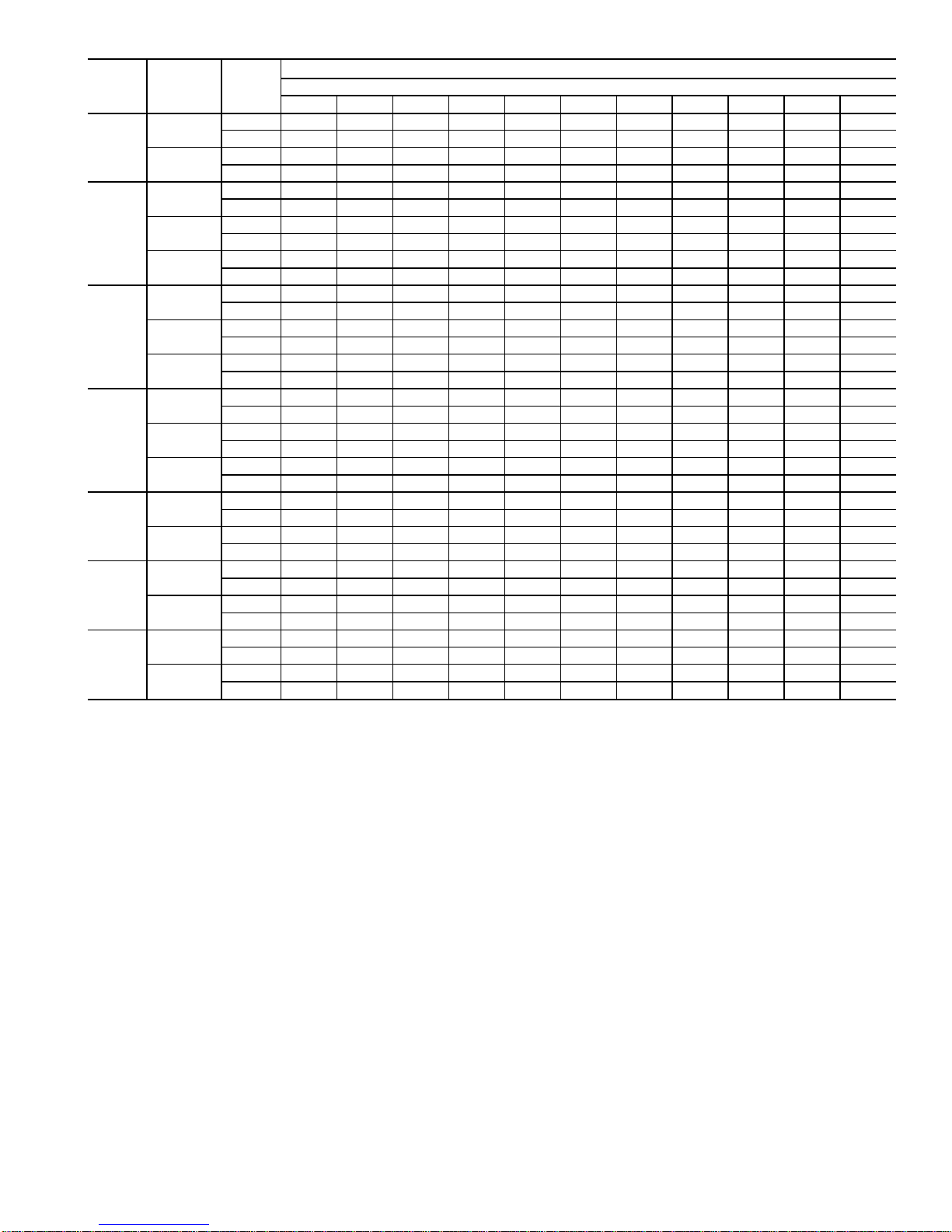
Table 6 — Dry Coil Air Delivery* — Horizontal Discharge (Deduct 10% for 208 v)
UNIT
SIZE
50HS
MOTOR
SPEED
230 AND 460 V HORIZONTAL DISCHARGE
External Static Pressure (in. wg)
0.0 0.1 0.2 0.3 0.4 0.5 0.6 0.7 0.8 0.9 1.0
018
Low
Watts 230 225 220 210 195 170 —————
Cfm760745725695640540—————
High
Watts ————270235200————
Cfm————850700450————
024
Low
Watts 280 275 265 255 250 245 240 ————
Cfm820810755700660600560————
Med
Watts 365 360 350 345 340 330 320 310 300 — —
Cfm 1025 1010 975 940 900 850 800 720 630 — —
High
Watts — — 490 480 470 460 445 430 410 390 380
Cfm — — 1300 1255 1200 1150 1080 1005 915 790 620
030
Low
Watts ———————————
Cfm———————————
Med
Watts — 365 360 360 350 350 —————
Cfm — 1060 1020 980 935 880 —————
High
Watts ————490485475460450430—
Cfm————1270 1220 1170 1100 1020 920 —
036
Low
Watts 520 495 474 458 495 425 —————
Cfm 1375 1335 1290 1244 1200 1146 —————
Med
Watts 575 560 535 510 480 460 440 425 — — —
Cfm 1520 1490 1450 1440 1380 1300 1200 1080 — — —
High
Watts ————650614575540510480—
Cfm————1560 1500 1380 1280 1170 1060 —
042
Low
Watts 730 700 680 645 615 580 535 490 430 — —
Cfm 1620 1590 1550 1510 1460 1390 1310 1210 1050 — —
High
Watts —————850800750700650610
Cfm—————1780 1670 1550 1400 1230 1050
048
Low
Watts 1080 1040 1020 970 910 840 785 730 680 620 540
Cfm 2100 2090 2080 2060 1980 1900 1810 1710 1590 1450 1200
High
Watts 1230 1190 1125 1060 1010 940 880 820 760 710 660
Cfm 2390 2340 2280 2210 2150 2030 1900 1770 1630 1480 1300
060
Low
Watts 1150 1100 1050 1010 950 900 850 800 730 650 —
Cfm 2500 2410 2330 2260 2170 2080 1990 1880 1750 1580 —
High
Watts —————117011101050 990 920 880
Cfm—————2470 2340 2200 2040 1870 1700
*Air delivery values are based on operating voltage of 230 v or
460 v, dry coil, without filter or electric heater. Deduct wet coil, filter,
and electric heater pressure drops to obtain external static pressure
available for ducting.
NOTES:
1. Do not operate the unit at a cooling airflow that is less than
350 cfm for each 12,000 Btuh of rated cooling capacity.Indoorcoil
frosting may occur at airflows below this point.
2. Dashes indicate portions of table that are beyond the blower motor capacity or are not recommended.
23
Page 24
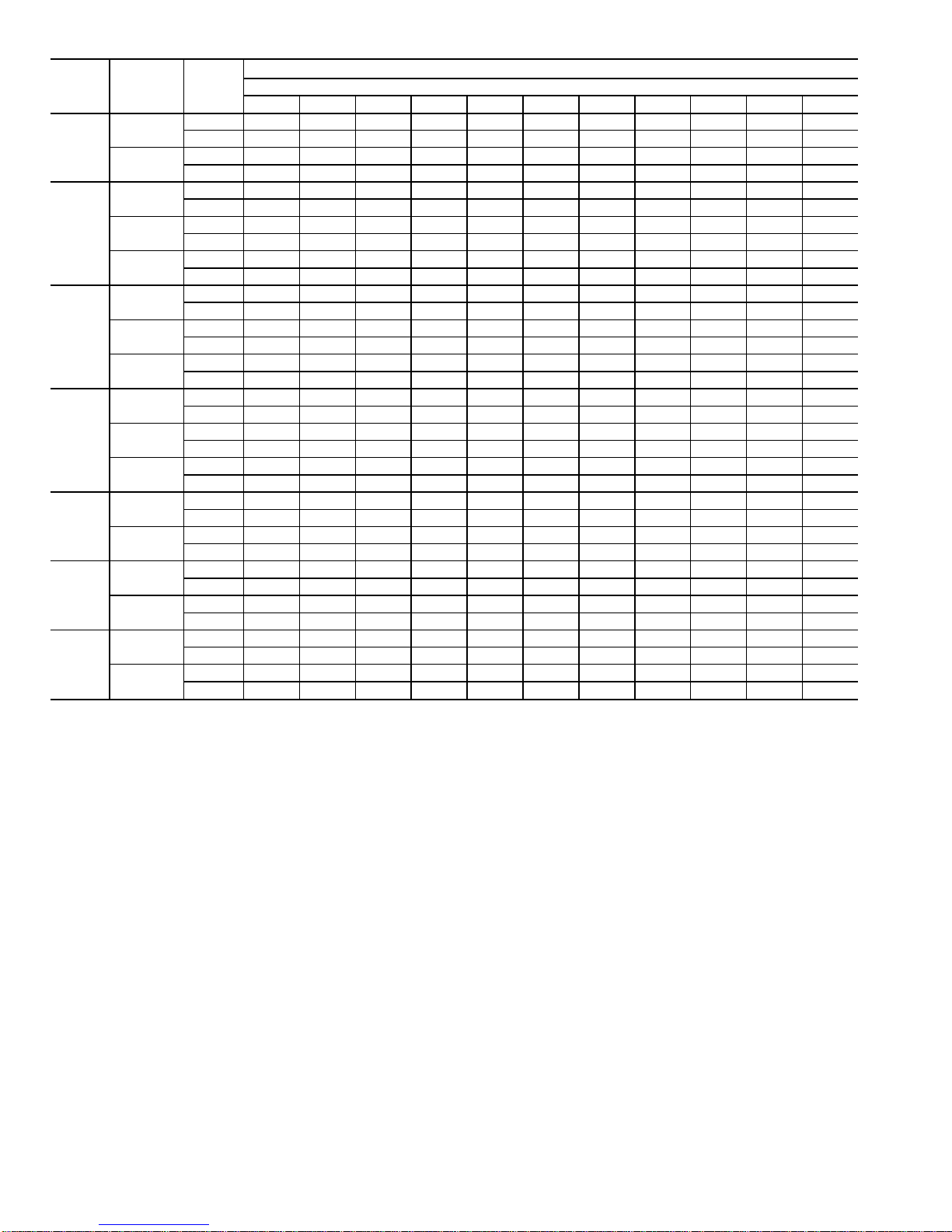
Table 7 — Dry Coil Air Delivery* — Vertical Discharge (Deduct 10% for 208 v)
UNIT
SIZE
50HS
MOTOR
SPEED
230 AND 460 V VERTICAL DISCHARGE
External Static Pressure (in. wg)
0.0 0.1 0.2 0.3 0.4 0.5 0.6 0.7 0.8 0.9 1.0
018
Low
Watts 230 225 220 210 195 170 —————
Cfm760745725695640540—————
High
Watts ————270235200————
Cfm————850700450————
024
Low
Watts 280 275 265 255 250 245 240 ————
Cfm820810755700660600560————
Med
Watts 365 360 350 345 340 330 320 310 300 — —
Cfm 1025 1010 975 940 900 850 800 720 630 — —
High
Watts — — 490 480 470 460 445 430 410 390 380
Cfm — — 1300 1255 1200 1150 1080 1005 915 790 620
030
Low
Watts ———————————
Cfm———————————
Med
Watts — 365 360 360 350 350 —————
Cfm — 1060 1020 980 935 880 —————
High
Watts ————490485475460450430—
Cfm————1270 1220 1170 1100 1020 920 —
036
Low
Watts 520 495 474 458 495 425 —————
Cfm 1375 1335 1290 1244 1200 1146 —————
Med
Watts 575 560 535 510 480 460 440 425 — — —
Cfm 1520 1490 1450 1440 1380 1300 1200 1080 — — —
High
Watts ————650614575540510480—
Cfm————1560 1500 1380 1280 1170 1060 —
042
Low
Watts 730 700 680 645 615 580 535 490 430 — —
Cfm 1620 1590 1550 1510 1460 1390 1310 1210 1050 — —
High
Watts —————850800750700650610
Cfm—————1780 1670 1550 1400 1230 1050
048
Low
Watts 1080 1040 1020 970 910 840 785 730 680 620 540
Cfm 2100 2090 2080 2060 1980 1900 1810 1710 1590 1450 1200
High
Watts 1230 1190 1125 1060 1010 940 880 820 760 710 660
Cfm 2390 2340 2280 2210 2150 2030 1900 1770 1630 1480 1300
060
Low
Watts 890 850 810 780 740 710 660 630 580 — —
Cfm 2500 2410 2330 2260 2170 2080 1970 1860 1700 — —
High
Watts — — — 1000 960 910 870 830 790 750 —
Cfm — — — 2480 2370 2250 2120 2000 1850 1690 —
*Air delivery values are based on operating voltage of 230 v or
460 v, dry coil, without filter or electric heater. Deduct wet coil, filter,
and electric heater pressure drops to obtain external static pressure
available for ducting.
NOTES:
1. Do not operate the unit at a cooling airflow that is less than
350 cfm for each 12,000 Btuh of rated cooling capacity.Indoorcoil
frosting may occur at airflows below this point.
2. Dashes indicate portions of table that are beyond the blower motor capacity or are not recommended.
24
Page 25
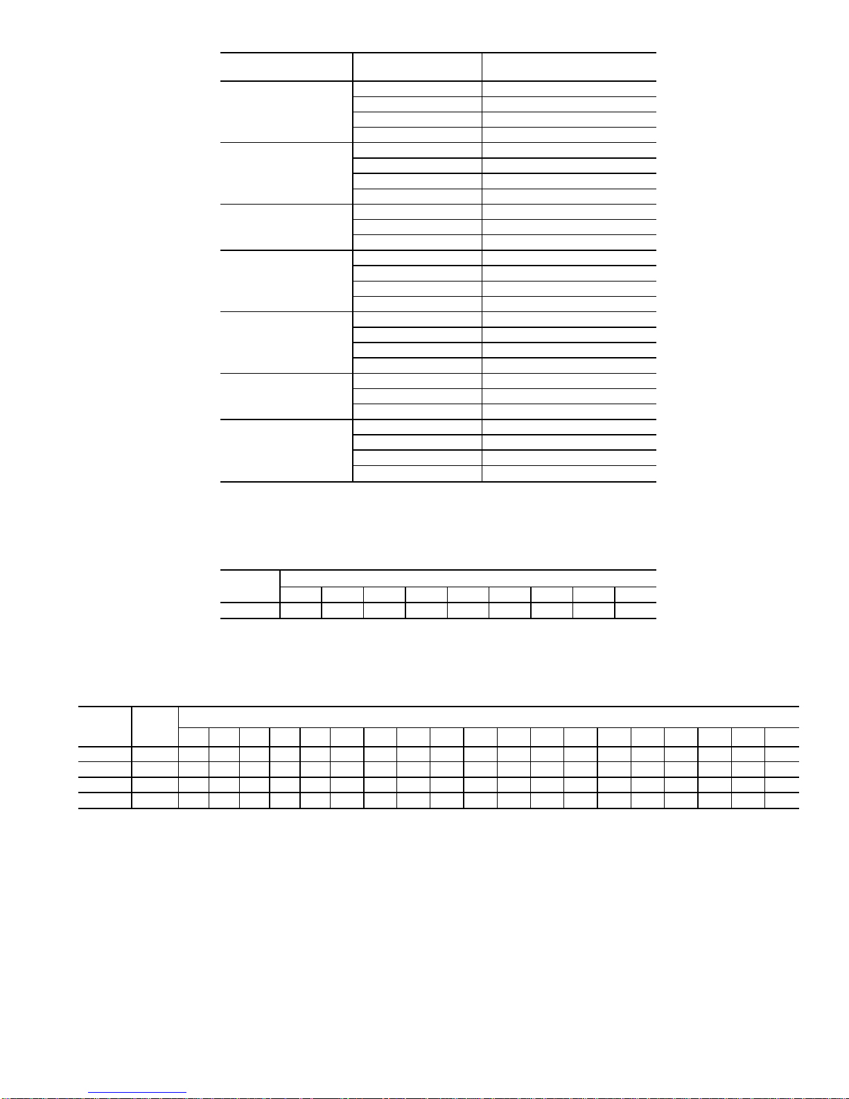
Table8—WetCoil Pressure Drop
UNIT SIZE
50HS
AIRFLOW
(cfm)
PRESSURE DROP
(in. wg)
018
600 0.069
700 0.082
800 0.102
900 0.116
024
600 0.039
700 0.058
800 0.075
900 0.088
030
900 0.088
1000 0.095
1200 0.123
036
1000 0.082
1200 0.102
1400 0.120
1600 0.143
042
1000 0.048
1200 0.069
1400 0.088
1600 0.102
048
1400 0.068
1600 0.075
1800 0.088
060
1700 0.082
1900 0.095
2100 0.108
2300 0.123
Table 9 — Accessory Electric Heater Pressure Drop (in. wg)
HEATER
kW
CFM
600 800 1000 1200 1400 1600 1800 2000 2200
5-20 0.030 0.033 0.037 0.042 0.047 0.052 0.060 0.067 0.075
Table 10 — Filter Pressure Drop (in. wg)
UNIT
SIZE
50HS
FILTER
SIZE
(in.)
CFM
500 600 700 800 900 1000 1100 1200 1300 1400 1500 1600 1700 1800 1900 2000 2100 2200 2300
018, 024 20 x 20 0.05 0.07 0.08 0.10 0.12 0.13 — ————————————
030 20x24————0.09 0.10 0.11 0.13 0.14 ——————————
036, 042 24x24—————0.08 0.09 0.10 0.11 0.12 0.14 0.15 ———————
048, 060 24x30—————— — — —0.09 0.10 0.11 0.12 0.13 0.14 0.15 0.16 0.17 0.18
25
Page 26
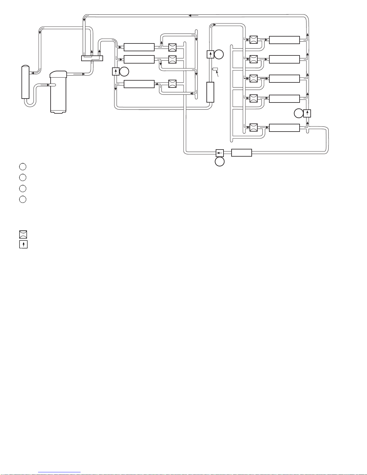
STRAINER
ACCUMULATOR
COMPRESSOR
STRAINER
LCS
OUTDOOR COIL
INDOOR COIL
A
B
D
C
*
LEGEND
LCS — Loss of Charge Switch
Acutrol™ Metering Device
Check Valve (Arrow indicates direction of flow)
*No outdoor coil check valve on 50HS048.
COOLING CYCLE
1. Hot gas from compressor flows through the 4-way valve and is
directed to the outdoor coil. It is then condensed and subcooled
through converging circuits. Refrigerant leaves the outdoor coil by
way of the strainer and the check valve in the cooling liquid line.
2. The refrigerant then feeds the indoor coil through the Acutrol
metering device on each circuit.
3. Each circuit evaporates the refrigerant and the circuits are combined in the indoor coil header with some of the circuits flowing
through the check valve.
4. The refrigerant then flows through the 4-way valve, accumulator,
and back to the compressor.
Fig. 28 — Typical Heat Pump Operation, Cooling Mode
Check Valves
A
Closed
B
Open
C
Closed
D
Open
26
Page 27
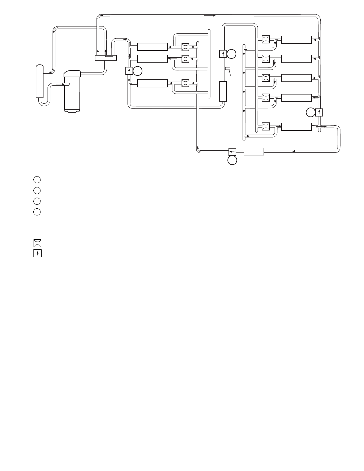
STRAINER
ACCUMULATOR
COMPRESSOR
STRAINER
LCS
OUTDOOR COIL
INDOOR COIL
A
B
D
C
*
LEGEND
LCS — Loss of Charge Switch
Acutrol™ Metering Device
Check Valve (Arrow indicates direction of flow)
*No outdoor coil check valve on 50HS048.
HEATING CYCLE
1. Hot gas from compressor flows through the 4-way valve and is
directed to the indoor coil. It is then condensed directed through
subcooling circuits and out to the strainer and the check valve in
the heating liquid line.
2. The refrigerant then feeds the outdoor coil through the Acutrol
metering device on each circuit.
3. Each circuit evaporates the refrigerant and the circuits are combinedintheoutdoorheader with some of the circuits flowing through
the check valve.
4. The refrigerant then flows through the 4-way valve, accumulator,
and back to the compressor.
Fig. 29 — Typical Heat Pump Operation, Heating Mode
Check Valves
A
Open
B
Closed
C
Open
D
Closed
27
Page 28
MAINTENANCE
To ensure continuing high performance, and to minimize
the possibility of premature equipment failure, periodic maintenance must be performed on this equipment. This heat pump
unit should be inspected at least once each year by a qualified service person. To troubleshoot units, refer to Table 11.
NOTE TO EQUIPMENT OWNER: Consult your local dealer
about the availability of a maintenance contract.
The ability to properly perform maintenance on this equipment requires certain expertise, mechanical skills, tools
and equipment. If you do not possess these, do not attempt to perform any maintenance on this equipment,
other than those procedures recommended in the
User’s Manual. FAILURE TO HEED THIS WARNING COULD RESULT IN SERIOUS PERSONAL
INJURY AND POSSIBLE DAMAGE TO THIS
EQUIPMENT.
Failure to follow these warnings could result in serious
personal injury:
1. Turn off electrical power to the unit before performing any maintenance or service on the unit.
2. Use extreme caution when removing panels and parts.
As with any mechanical equipment, personal injury
can result from sharp edges.
3. Never place anything combustible either on, or in contact with, the unit.
The minimum maintenance requirements for this equip-
ment are as follows:
1. Inspect air filter(s) each month. Clean or replace when
necessary.
2. Inspect indoor coil, drain pan, and condensate drain each
cooling season for cleanliness. Clean when necessary.
3. Inspect blower motor and wheel for cleanliness and check
lubrication each cooling season. Clean and lubricate when
necessary.
4. Check electrical connections for tightness and controls
for proper operation each cooling season. Service when
necessary.
Air Filter
Never operate the unit without a suitable air filter in the
return-air duct system. Always replace the filter with the
same dimensional size and type as originally installed.
See Table 1 for recommended filter sizes.
Inspect air filter(s) at least once each month and replace
(throwaway-type) or clean (cleanable-type) at least twice during each cooling season or whenever the filters become clogged
with dust and lint.
Unit Top Removal
NOTE: When performing maintenance or service procedures that require removal of the unit top, be sure to perform
all of the routine maintenance procedures that require top
removal, including coil inspection and cleaning, and condensate drain pan inspection and cleaning.
Only qualified service personnel should perform maintenance and service procedures that require unit top removal.
Refer to the following top removal procedures:
1. Remove7screws on unit topcover surface. (Save all screws.)
2. Remove4 screws on unit top cover flange. (Save all screws.)
3. Lift top from unit carefully. Set top on edge and make
sure that top is supported by unit side that is opposite
duct (or plenum) side.
4. Carefully replace and secure unit top to unit, using screws
removed in Steps 1 and 2, when maintenance and/or service procedures are completed.
Indoor Blower and Motor
NOTE: Motors without oilers are prelubricated. Do not attempt to lubricate these motors.
For longer life, operating economy, and continuing efficiency, clean accumulated dirt and grease from the blower
wheel and motor annually.
Lubricate the motor every 5 years if the motor is used intermittently (thermostat FAN switch in AUTO. position), or
every 2 years if the motor is used continuously (thermostat
FAN switch in ON position).
Disconnect and tag electrical power to the unit before
cleaning and lubricating the blower motor and wheel.
Failure to adhere to this warning could cause personal
injury or death.
To clean and lubricate the blower motor and wheel:
1. Remove and disassemble blower assembly as follows:
a. Remove blower access door.
b. Disconnect motor lead from indoor-fan contactor (IFC).
Disconnect yellow motor lead from terminal L2 or 23
of the contactor.
c. Remove blower assembly from unit. Be careful not to
tear insulation in blower compartment.
d. Ensure proper reassembly by marking blower wheel
and motor in relation to blower housing before
disassembly.
e. Loosen setscrew(s) which secure wheel to motor shaft.
Remove screws that secure motor mount brackets to
housing and slide motor and motor mount out of
housing.
2. Lubricate motor as follows:
a. Thoroughly clean all accumulations of dirt or grease
from motor housing.
b. Remove dust caps or plugs from oil ports located at
each end of motor.
c. Use a good grade of SAE (Society of Automotive
Engineers) 20 nondetergent motor oil and put one teaspoon (5 cc,
3
⁄16oz., or 16 to 25 drops) in each oil port.
d. Allow time for oil to be absorbed by each bearing,
then wipe excess oil from motor housing.
e. Replace dust caps or plugs in oil ports.
3. Remove and clean blower wheel as follows:
a. Ensure proper reassembly by marking wheel orienta-
tion and cutoff plate location.
b. Remove screws holding cut-off plate, and remove plate
from housing.
28
Page 29
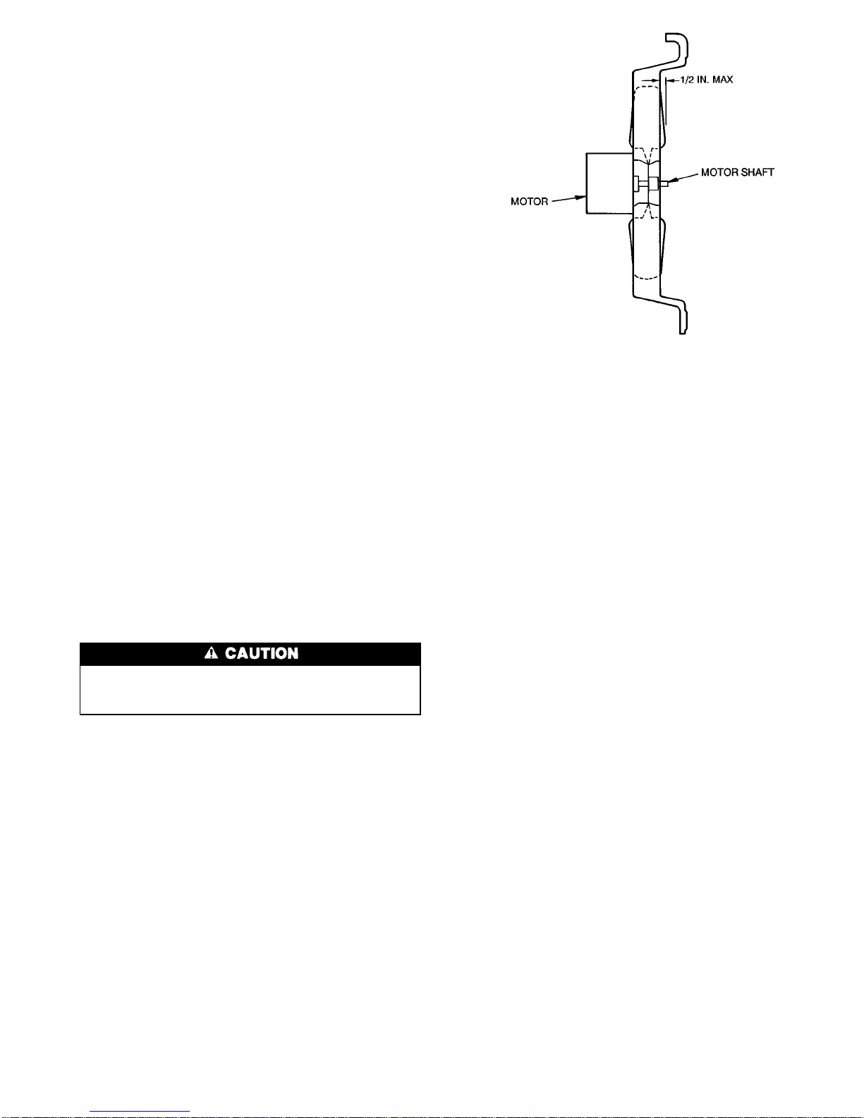
c. Lift wheel from housing. When handling and/or clean-
ing blower wheel, be sure not to disturb balance weights
(clips) on blower wheel vanes.
d. Remove caked-on dirt from wheel and housing with a
brush. Remove lint and/or dirt accumulations from wheel
and housing with vacuum cleaner, using soft brush at-
tachment. Remove grease and oil with mild solvent.
e. Reassemble wheel and cut-off plate into housing.
f. Reassemble motor into housing. Be sure setscrews are
tightened on motor-shaft flats and not on round part of
shaft.
OutdoorCoil, Indoor Coil, and CondensateDrain
Pan —
Inspect the outdoor coil, indoor coil, and condensate drain pan at least once each year. Proper inspection and
cleaning requires the removal of the unit top. See Unit Top
Removal section on page 28.
The coils are easily cleaned when dry; inspect and clean
the coils either before or after each cooling season. Remove
all obstructions (including weeds and shrubs) that interfere
with the airflow through the outdoor coil. Straighten bent
fins with a fin comb. If coated with dirt or lint, clean the
coils with a vacuum cleaner, using a soft brush attachment.
Be careful not to bend the fins. If coated with oil or grease,
clean the coils with a mild detergent-and-water solution. Rinse
coils with clear low-velocity water, using a garden hose. Be
careful not to splash water on motors, insulation, wiring, or
air filter(s). For best results, spray outdoor coil fins from inside to outside the unit. On units with an outer and inner
outdoor coil, be sure to clean between the coils. Be sure to
flush all dirt and debris from the unit base.
Inspect the drain pan and condensate drain line when inspecting the coils. Clean the drain pan and condensate drain
by removing all foreign matter from the pan. Flush the pan
and drain tube with clear water. Do not splash water on the
insulation, motor, wiring, or air filter(s). If the drain tube is
restricted, clear it with a ‘‘plumbers snake’’or similar probe
device. Ensure that the auxiliary drain port above the drain
tube is also clear.
Outdoor Fan
Keep the condenser fan free from all obstructions to ensure proper cooling operation. Never place articles on
top of the unit. Damage to unit may result.
1. Remove screws at bottom of outdoor air intake grille and
remove plastic grille.
2. Inspect the fan blades for cracks or bends.
3. If fan needs to be removed, loosen the setscrew and slide
the fan off the motor shaft.
4. When replacing fan blade, position blade so that leading
edge is 2 in. back from outdoor inlet grille or
1
⁄2in. maxi-
mum from the fan deck. See Fig. 30.
5. Ensure that setscrew engages the flat area on the motor
shaft when tightening.
Electrical Controls and Wiring— Inspect and check
the electrical controls and wiring annually. Be sure to turn
off the electrical power to the unit.
Remove the control/blower and compressor compartment
access panels to locate all the electrical controls and wiring.
Check all electrical connections for tightness.Tightenall screw
connections. If any smoky or burned connections are noticed, disassemble the connection, clean all the parts, restrip
the wire end and reassemble the connection properly and
securely.
After inspecting the electrical controls and wiring, replace all the panels. Start the unit, and observe at least one
complete cooling cycle to ensure proper operation. If discrepancies are observed in operating cycle, or if a suspected
malfunction has occurred, check each electrical component
with the proper electrical instrumentation. Refer to the unit
wiring label when making these checkouts.
NOTE: Refer to the Sequence of Operation section on
page 22 as an aid in determining proper control operation.
RefrigerantCircuit — Inspect all refrigerant tubing con-
nections and the unit base for oil accumulations annually.
Detecting oil generally indicates a refrigerant leak.
If oil is detected or if low performance is suspected, leaktest all refrigerant tubing using an electronic leak detector,
or liquid-soap solution. If a refrigerant leak is detected, refer
to Check for Refrigerant Leaks section on page 18.
If no refrigerant leaks are found and low performance is
suspected, refer to Checking and Adjusting Refrigerant Charge
section on page 18.
Fig. 30 — Fan Blade Clearance
29
Page 30
Indoor Airflow — The indoor airflow does not require
checking unless improper performance is suspected. If a problem exists, be sure that all supply- and return-air grilles are
open and freefromobstructions, and that the air filter is clean.
When necessary, refer to Indoor Airflow and Airflow Adjustments section on page 22 to check the system airflow.
Metering Devices — Refrigerant metering devices are
fixed orifices and are located in the inlet header to the indoor
and outdoor coils.
Liquid Line Strainers — The liquid line strainers (to
protect metering device) are made of wire mesh and are located in the liquid lines on the inlet side of the metering
devices.
Check valves are also located in the liquid lines near
the strainers. The strainers are the larger of the two
components.
Table 11 — Cooling and Heating Troubleshooting Chart
SYMPTOM CAUSE REMEDY
Compressor and outdoor fan will not start.
Power failure Call power company.
Fuse blown or circuit breaker tripped Replace fuse or reset circuit breaker.
Defective thermostat, contactor, transformer,
control relay, or defrost board
Replace component.
Insufficient line voltage Determine cause and correct.
Incorrect or faulty wiring Check wiring diagram and rewire correctly.
Thermostat setting too high Lower thermostat setting below room temperature.
Units have a 5-minute time delay DO NOT bypass this compressor time delay — wait
for 5 minutes until time-delay relay is deenergized.
Compressor will not
start but outdoor fan
runs.
Faulty wiring or loose connections in
compressor circuit
Check wiring and repair or replace.
Compressor motor burned out, seized, or
internal overload open
Determine cause. Replace compressor.
Defective run capacitor, overload,
or PTC (positive temperature coefficient)
thermistor
Determine cause and replace.
One leg of 3-phase power dead Replace fuse or reset circuit breaker.
Determine cause.
Low input voltage (20% low) Determine cause and correct.
Three-phase scroll
compressor
(size 048 and 060
units only) makes excessive noise, and
there may be a low
pressure differential
Scroll compressor is rotating in the
wrong direction
Correct the direction of rotation by reversing the
3-phase power leads to the unit.
Compressor cycles
(other than normally
satisfying thermostat).
Refrigerant overcharge or undercharge Recover refrigerant, evacuate system, and recharge
to capacities shown on nameplate.
Defective compressor Replace and determine cause.
Insufficient line voltage Determine cause and correct.
Blocked outdoor coil Determine cause and correct.
Defective run/start capacitor, overload,
or start relay
Determine cause and replace.
Defective thermostat Replace thermostat.
Faulty outdoor-fan motor or capacitor Replace.
Damaged reversing valve Determine cause and correct.
Restriction in refrigerant system Locate restriction and remove.
Compressor operates
continuously.
Dirty air filter Replace filter.
Unit undersized for load Decrease load or increase unit size.
Thermostat set too low Reset thermostat.
Low refrigerant charge Locate leak, repair and recharge.
Leaking valves in compressor Replace compressor.
Frosted coil with incorrect defrost operation Check defrost time settings. Reset as necessary.
Check defrost temperature switch. Replace as necessary.
Air in system Recover refrigerant, evacuate system, and recharge.
Outdoor coil dirty or restricted Clean coil or remove restriction.
30
Page 31
Table 11 — Cooling and Heating Troubleshooting Chart (cont)
SYMPTOM CAUSE REMEDY
Excessive head
pressure.
Dirty air filter Replace filter.
Dirty indoor or outdoor coil Clean coil.
Refrigerant overcharged Recover excess refrigerant.
Air in system Recover refrigerant, evacuate system, and recharge.
(Heat) Indoor air restricted or recirculating Determine cause and correct.
Indoor or outdoor air restricted or
air short-cycling
Determine cause and correct.
Head pressure too low. Low refrigerant charge Check for leaks, repair and recharge.
Compressor valves leaking Replace compressor.
Restriction in liquid tube Remove restriction.
Excessive suction
pressure.
(Heat) Outdoor coil frosted Move timer on control board to 30 minutes
between defrost cycles.
(Cool) High heat load Check for source and eliminate.
Compressor valves leaking Replace compressor.
Reversing valve hung up or leaking internally Replace valve.
Refrigerant overcharged Recover excess refrigerant.
Suction pressure too
low.
(Cool) Dirty air filter Replace filter.
(Heat) Outdoor coil frosted Move timer on control board to 30 minutes
between defrost cycles.
Low refrigerant charge Check for leaks, repair and recharge.
Metering device or low side restricted Remove source of restriction.
(Cool) Insufficient coil airflow Increase air quantity. Check filter — replace if
necessary.
(Cool) Temperature too low in conditioned area Reset thermostat.
(Cool) Outdoor ambient below 40 F Install low-ambient kit.
Field-installed filter-drier restricted Replace.
Compressor runs but
outdoor fan does not.
Normally closed contacts on defrost board open Check condition of relay on board. Replace if necessary.
31
Page 32

Page 33

Page 34
Copyright 1997 Carrier Corporation
Manufacturer reserves the right to discontinue, or change at any time, specifications or designs without notice and without incurring obligations.
Book 1 4
Tab 5a 5a
PC 111 Catalog No. 565-041 Printed in U.S.A. Form 50HS-9SI Pg 34 2-97 Replaces: 50HS-8SI
Page 35

Page 36
START-UP CHECKLIST
(Remove and Store in Job File)
I. PRELIMINARY INFORMATION
MODEL NO.:
DATE:
SERIAL NO.:
TECHNICIAN:
II. PRE-START-UP (insert checkmark in box as each item is completed)
M VERIFY THAT ALL PACKING MATERIALS HAVE BEEN REMOVED FROM UNIT
M VERIFY THAT CONDENSATE CONNECTION IS INSTALLED PER INSTALLATION INSTRUCTIONS
M CHECK ALL ELECTRICAL CONNECTIONS AND TERMINALS FOR TIGHTNESS
M CHECK THAT INDOOR-AIR FILTER IS CLEAN AND IN PLACE
M VERIFY THAT UNIT INSTALLATION IS LEVEL
M CHECK FAN WHEEL AND PROPELLER FOR LOCATION IN HOUSING/ORIFICE AND SETSCREW
TIGHTNESS
III. START-UP
ELECTRICAL
SUPPLY VOLTAGE L1-L2
L2,L3 L3-L1
COMPRESSOR AMPS L1 L2 L3
INDOOR-FAN AMPS
TEMPERATURES
OUTDOOR-AIR TEMPERATURE
DB (DRY BULB)
RETURN-AIR TEMPERATURE
DB WB (WET BULB)
COOLING SUPPLY AIR
ELECTRIC HEATER SUPPLY AIR
PRESSURES (COOLING)
REFRIGERANT SUCTION
PSIG
REFRIGERANT DISCHARGE
PSIG
M VERIFY REFRIGERANT CHARGE USING CHARGING CHARTS ON PAGES 19-21.
M VERIFY 3-PHASE SCROLL COMPRESSOR (048,060 ONLY) IS ROTATING IN CORRECT DIRECTION.
----------------------------------------------------------------------------------------
CUT ALONG DOTTED LINE CUT ALONG DOTTED LINE
Copyright 1997 Carrier Corporation
Manufacturer reserves the right to discontinue, or change at any time, specifications or designs without notice and without incurring obligations.
Book 1 4
Tab 5a 5a
PC 111 Catalog No. 565-041 Printed in U.S.A. Form 50HS-9SI CL-1 2-97 Replaces: 50HS-8SI
 Loading...