

Page 1
Carrier Parkway • Syracuse NY 13221
Single-Package Cooling Units
INSTALLATION
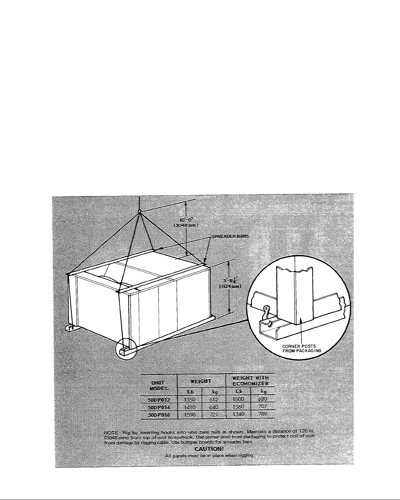
Rigging and Unit Placement — Inspect unit for
transportation damage. File any claim with trans
portation agency. Do not drop unit. Keep unit
upright. Use spreader bars over unit to prevent
sling or cable damage. Rollers may be used to move
unit across a roof. Level unit by using unit frame as
a reference; unit leveling tolerance is ±1/16 in. per
linear ft in any direction. See Fig. 1 for additional
information. Unit weight is shown in Table 1.
Four lifting holes are provided in ends of unit
base rails as shown in Fig. 1. Refer to rigging
instructions on unit. Refer to Accessory Roof Curb
Installation Instructions for additional information
as required.
Roof Curb — Assemble and install accessory roof
curb in accordance with instructions shipped with
this accessory. Refer to Fig. 2. Accessory roof curb
and information required to field fabricate a roof
curb of 2 in. X 12 in. planks is shown in Fig. 2.
Install insulation, cant strips, roofing and flashing
as shown. Ductwork can be installed to roof curb
before unit is set in place. Curb should be level.
Unit leveling tolerance is ±1/16 in. per linear ft in
any direction. This is necessary to permit unit
drain to function properly.
Parrlor Pnrnnratinn 1Q7Q
Fig. 1 — Rigging Details
Form 50DP-9SI
Page 2
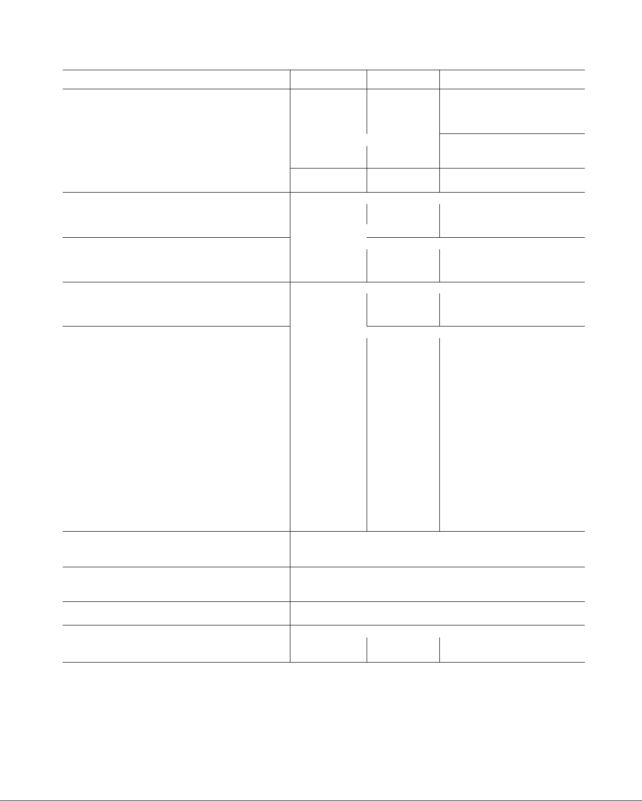
Table 1 — Physical Data
UNIT SIZE 50DP
OPERATING WT (lb)
Unit
With Economizer
Roof Curb
COMPRESSOR
No. ... Type 2 ... P64
Oil (oz)
REFRIGERANT (Capillary Control) R-22
Charge (lb) Sys 1*, Sys 2
OUTDOOR COIL
Rows 2
F ins/in.
Total Face Area (sq ft)
OUTDOOR AIR FAN
Nominal Cfm
No. ... Diam (in.)
Motor Hp (1075 Rpm) 1/2
INDOOR COIL
Rows
F ins/in.
Total Face Area (sq ft)
INDOOR BLOWER
Qty ... Size (in.)
Nominal Cfm
Rpm Range
Max Allowable Rpm
Motor Pulley Pitch Diam (in.)
Fan Pulley Pitch Diam (in.)
Belt, No. ... Type ... Length (in.)
Speed Change per Full Turn Std
of Moveable Pulley Flange (Rpm) Opt
Moveable Pulley Max Full Turns
from Closed Position
Factory Setting - Full Turns Open
Factory Speed Setting (Rpm)
Motor Hp (Service Factor)
HIGH PRESSURE SWITCH
Cutout (psig)
Reset (psig) 320
LOW PRESSURE SWITCH (Liquid Line)
Cutout (psig)
Reset (psig)
AIR INLET SCREENS
Economizer, No. ... Size (in.)
INDOOR AIR FILTERS (Type)
No. ... Size (in.)
Std 753-1066
Std 2 4-3.4
Std
Std 1 (1.25)
012
1350
1500
200
Hermetic -
76 ea
7 9, 6.6
14
18.9
9000
2 ..22
2
14
14.7
2 .. 10x10
4000
878-1191
1550
2.8-3.8
5.5
5.5
1 ... V .. 41
62
63
5
753
878
1-1/2 (1.20)
2 ... 16x20x2
4 .. 16x25x2 4 ... 16x23x2
- 2 Cy t inders
10% efficient — 2-in. D isposable Fiber Glass
014
1410
1560
200
2 ... P77
76 ea
R-22
8 3, 8.3
Copper Tube, Aluminum Plate Fins/in.
3
14
18 9
Prope 1 ler Type.
8000
2 22
1/2
Copper Tube, Aluminum Plate Fins/in
3
15
13.8
........................ _ .... .
Centrifugal, Adjustable Belt Drive
.............................................
2 10x10
5000
805-1093
978-1265
1550
2 8-3.8
3.4-4 4
6.0
6.0
1 ... V . 43
58
57
5
805
978
2 (1.15)
3 (1.15)
2 ... 20x25x1
1 .. 20x20x1
2 16x20x2
Direct Drive
428
27
60
016
1590
1740
200
Semi-Hermetic — 6 Cylinders
1 . 06DA537
160
R-22
23.2, -
3
14
18 9
12,000
2 ... 26
1
3
14
16.5
2 .. 10 X 10
6000
916-1 186
1158-1428
1550
3.4-4.4
4.3-5.3
6.4
6.4
1 . V ... 45
54
55
5
916
1158
3 (1 15)
3 (1 15)
4 ... 20x20x2
4 .. 16x20x2
t
•System 1 consists of upper portion of outdoor coil and lower portion of indoor coil
Page 3
Roof Mount — Check building codes for weight
distribution requirements. Unit weight is shown in
Table 1.
Alternate Unit Support Methods — Where the curb
cannot be used, support unit with sleepers using
unit curb support area. If sleepers cannot be used,
support long sides of unit with a minimum of
3 equally spaced 4-in. x 4-in. pads on each side.
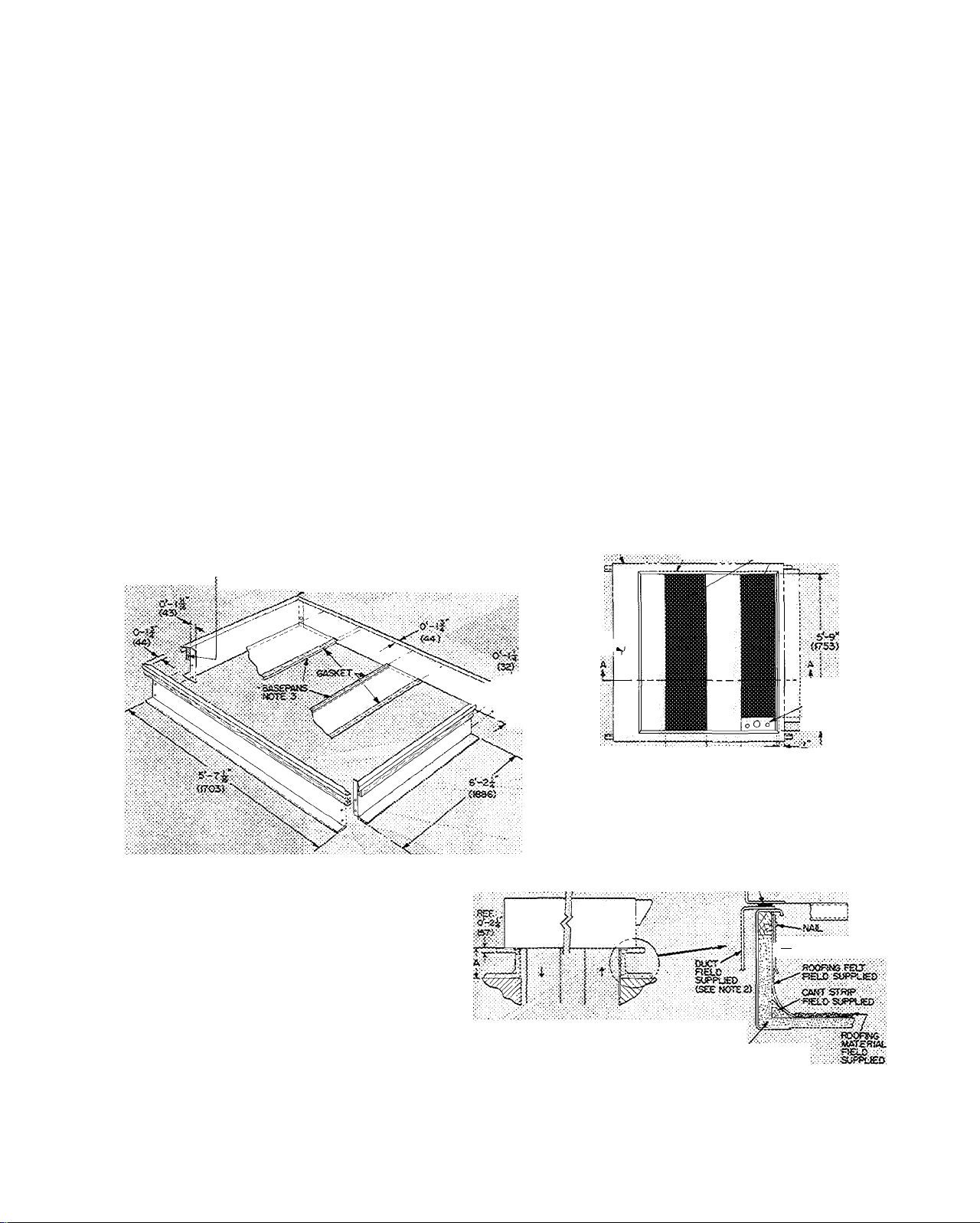
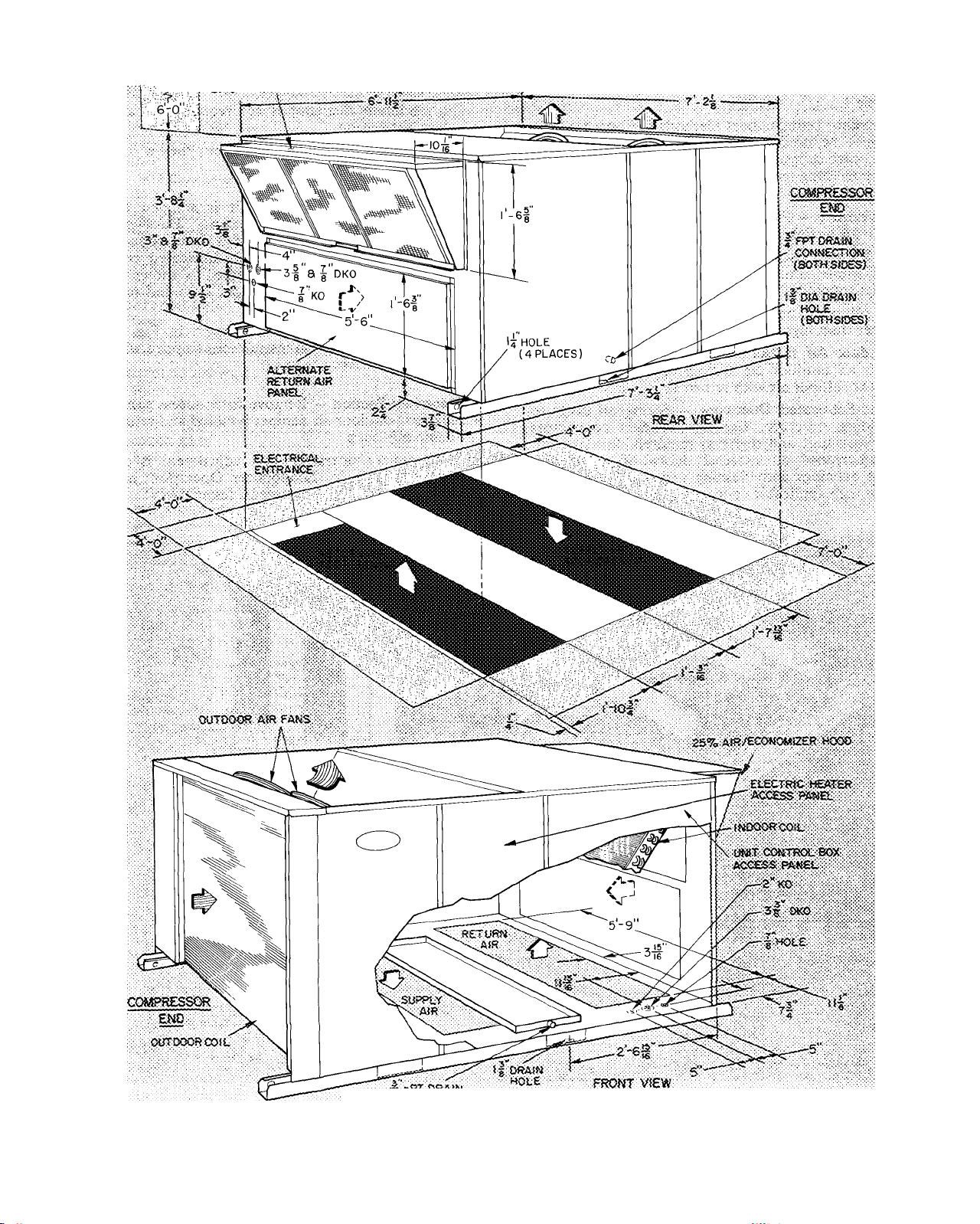
Positioning — Provide clearance around and above
unit for airflow, safety and service access. (Fig. 3)
Do not install unit in an indoor location. Do
not locate unit air inlets near exhaust vents or
other sources of contaminated air.
Although unit is weatherproof, guard against
water from higher level runoff and overhangs.
Outdoor Air Intake — The unit can be equipped
with an outdoor air damper (economizer) which
mixes outdoor air with return air.
Field-Fabricated Ductwork — Secure all ducts to
building structure. Use flexible duct connectors
between unit and ducts as required. Insulate and
weatherproof all external ductwork, joints and
roof openings with flashing and mastic in accord
ance with applicable codes.
Ducts passing thru • an unconditioned space
must be insulated and covered with a vapor barrier.
A minimum clearance is not required for any
air duct installation.
Outlet grilles must not lie directly below unit
discharge.
Unit Duct Connections — Unit is shipped for
thru'the-bottom duct connections. Ductwork
openings are shown in Fig. 2 and 3. Duct connec
tions are shown in Fig. 4. Field-fabricated con
centric ductwork may be connected as shown in
Fig. 5. Attach all ductwork to roof curb and roof
curb basepans.
Concentric duct details are shown in Fig. 6.
Also, refer to installation instructions shipped with
accessory roof curb.
Economizer Section — Remove filter access panel.
Check that outdoor air damper is closed and return
air damper is open.
Economizer operation and adjustment is de
scribed in Start-Up, Economizer Operation; and
Service, Economizer Adjustment, respectively.
•î33)io«K>'
4 PLACÉS.
Dmçmims
unît
50S>f>OÎ2/<Ji4 ölÄ
■-0
ms)
to-i-Uÿ 5
MTSRSO COf»<S»
yÇ!<»0№:'A
TYPS
OurUN£:«:««T
CCMR ^
SECTiOiî^
ftAfiViÉA'OÉ ^
/ROOF CORS ,/V
: ‘-jT-; !-K>5r
GASKET (S'JPPl.iSO
WTH OURS)
r*
ROOF Oi^i«S
f atCTfsou.
^ SECT(0N
; V
0-S^«32i
. COÜRTES FLASHING
-------
f£iS> Süfw=Ct£D
NOT£Sî
'. OiTOerisSoos io paiGfftïwisis i 5 «srs miliimetefs,
AtTRCSi CÄ} iJ:K5tWOr){ TO fooi'curo
3. c« tiOPscsg&-oîbasepaos teibre sostatffOij mix.
Fig. 2 — Roof Curb Details — 50DP012,014,016
SSCTK5» A-A
ÎS«PΫSUÎ.AriON
FiElP StJPPCiED
Page 4
~T
-----
7 2S?5i>Af«/aX)N0M}2Ef?ti00a. .
t
[^IMOOOR Ai'?FLOW
a "=>T ORAtN
-JCUTOOO'i AtRELOV/
Fig. 3 — Physical Data and Dimensions
>Aa£RNAT£ AiRfLOW
------
! SPACE RECUIREC FOR
.....J SERVSCE AND AtRFUOW
Page 5
Outside Air Damper (25% ventilation dir) -- Outside
air damper can be adjusted to permit up to 25%
outdoor air entry into return air compartment.
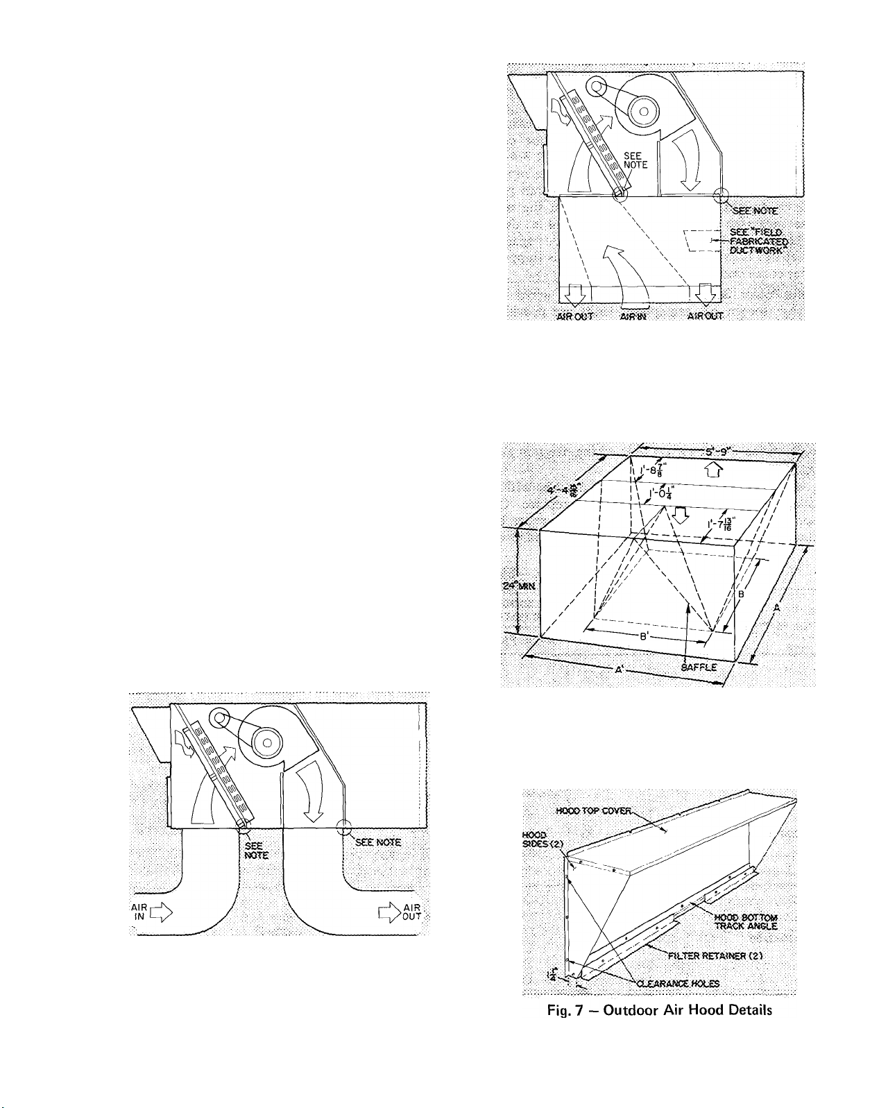
Outdoor Air Hood Installation (Fig. 3) — The
outdoor air hood is common to 25% air ventilation
and economizer. The economizer and all electrical
connections are factory installed and adjusted. The
hood assembly, outdoor air inlet screen(s) and
required hardware are shipped in a carton located
on outdoor fan section and must be field installed.
Using screws in carton install hood as follows;
1. Assemble hood top cover, side panels and
bottom track angle (Fig. 7).
Loosen base unit top cover sheet metal screws
2.
located above outdoor air inlet opening.
3.
Match notches in hood top cover to unit top
cover screws. Insert hood flange between unit
top cover flange and unit. Tighten screws.
4
Secure hood sides and bottom track angle to
unit. The screw on unit that matches bottom
track angle center hole must be removed prior
to assembly. Re-use screw to secure bottom
track angle to unit.
Insert outdoor air filters and spacer in hood
5.
filter tracks. NOTE: Hood may also be installed
by individually attaching hood parts to base
unit following sequence above.
6. Attach filter retainers to bottom track angle.
Indoor Blower — Blower belts and pulleys are
factory installed. Belts are secured to pulleys with
tape. Remove tape and, if required, adjust as
described in Service, Indoor Blower Adjustment.
Condenser Air Fans and Motors are factory set.
Refer to Service, Condenser Air Fan Adjustment as
required.
NOTE: Do not drill in this area, damage to basepan may result in
water leak
Fig. 5 — Concentric Duct Air Distribution
NOTE: Do not drill in this area, damage to basepan may result in
water leak
Fig. 4 — Air Distribution — Thru-the-Bottom
NOTE: Dimension A, A1 and B, B1 are obtained from field-supplied
ceiling diffuser
Fig. 6 — Concentric Duct Details
Page 6

Condensate Drain — See Fig. 3 and 8 for drain
locations. Plugs are provided in both drain holes
and at least one must be removed when unit is
operating. Two 3/4-in. half couplings are provided
inside the unit evaporator section for the con
densate drain connection(s). An 8 1/2-in. x 3/4-in.
diameter and 2 in. x 3/4-in. diameter pipe nipple
coupled to standard 3/4-in. diameter elbows pro
vide a straight path down thru holes in the unit
base rails (see Fig. 9). A trap at least 4 in. deep
must be used and must be protected against
freeze-up. If only one drain connection is trapped,
other connection must be plugged.
Field Power Supply — Unit is factory wired for
voltage shown on nameplate. Units are provided
with terminal block.
When installing units, provide a disconnect per
NEC of adequate size. (Table 2, 3, 4.)
All field wiring must comply with National
Electrical Code and local requirements.
Route power lines thru control box end panel
— or unit basepan — (Fig. 3) to terminal
connections as shown on unit wiring diagram and
Fig. 10.
Operating voltage to compressor must be within
voltage range indicated on unit nameplate. On
3-phase units, voltages between phases must be
balanced within 2% and the current must be
drain i| drain hole
CONNECTION (BOTH SIDES)
Fig. 8 — Condensate Drain Details
3'ppT
* rSAÌWCOKfiECTlOÌ'ÌU_____
(HAt.fCOyPt.iSSi p i
SASEftfiit.
r
TO TRAP •5'
r
I
Fig. 9 — Condensate Drain Piping Details
f
VOLTS/PH/HZ
200/3/60
230/3/60
460/3/60 414 508
575/3/60 518 632
VOLTAGE
RANGE
Max RLA LRA
Min
220 24
180
207
253
COMPR
20.9
10.5
8.3
Table 2 — Electrical Data; 50DP012
OUTDOOR
FAN MOTOR
Qty
113 2
98 2
49 2.1
41
2
2 1.8
FLA
4 6
3.8
INDOOR
FAN MOTOR
FLA FLA
Hp
1 3 45
5.5
1.5
1
3 45
1 3.45
1
3 45
1 3.45 156
5.5 39 18.8
1.5
5.5 72
1.5
1.5 5.5
5.5
1.5
1 3.2
1.5 5.1
1
3.2
1
3.2
1
3 2
1.5 5.1
1 5 5.1
1.5 5.1
1 1.6
2.Ó
1.5
1 1.6
1
1 Ó
1 1.6
2.6
1 5
1.5 2.6
2.6 66
1.5
1
1 35
1 7
1 5
FACTORY INSTALLED
HEATERS
Nom Kw
_
—
39
72
117 56.1 155
117
156
— -
47 18.8 65 70
82
135
47 18.8
82 34 2
135 56.1
_
— -
21
39 32.4
66 55 0 85
21
39 32.4 55
“
--
18.8
34 2 100 90
74.8 205
34.2
56.1
74.8
—
34 2
56.1
—
17.1 30
17.1
55.5
-
POWER
Min Ckt
Amps
SUPPLY
Max Fuse
70
70 7$
70 70
• ••
70
100
155
205 175
60
60
1 10
180
65
110
180 i7d
30
35 35
55
35
90
25
25
Amps
70
1 oO
175
9>3
150
' 70'
no
35
3S
50
30
3S
50
30
25
2.5
..........
«
Compr — Compressor
FLA — Full Load Amps
Hp — Horsepower
— Locked Rotor Amps
LRA
— Rated Load Amps
RLA
• .1 Fuse only; unshaded values indicate fuses or circuit breakers
may be used
Page 7

Table 3 — Electrical Data; 50DP014
VOLTAGE
VOLTS/PH/HZ
200/3/60 180 220 27.0
230/3/60 207 253 22.8
460/3/60
575/3/60
Compr — Compressor
FLA — Full Load Amps
Hp — Horsepower
RANGE
Min
414
518 632 9.3
COMPR
Max
508 11.6
LRA Qty FLA
RLA
160
137 2
69 2
55
LRA — Locked Rotor Amps
RLA — Rated Load Amps
OUTDOOR
FAN MOTOR
2 4.6
4 5
2.3
2 1 8
INDOOR
FAN MOTOR
FLA
Hp
2.0
3.0
2.0 7 4
2 0
2.0
2.0
3.0 8.4
3.0
3.0
3 0 8.4 156 74 8 210 200
2.Ò 6.6
3.0 8 4
2.0 6 6
2 0
2 0
3 0
3.0
3.0 8.4
2 0 3.3
3.0
2.0
2.0
2 0
3 0 4 2
3.0 4.2
3.0 4.2
2 0
3,0
7 4
8.4
7.4
7 4
7.4
8.4 72
8.4
6.6
6.6
8.4
8.4
4.2
3 3
3.3
3.3
2 3
3.8
FACTORY INSTALLED
HEATERS
FLA Nom Kw
__
— —
39
72 34 2 100
117
156
39
117
_ __
- -
47 18.8 70
82
135
47
82
135
__
— _
21
39
66
21
39 32.4 55
66 55 0
-
Fuse only; unshaded values indicate fuses or circuit breakers
may be used
18.8 80 90
56.1
74.8
18.8 80 ■ ■■ ■ 90
34.2 105
56 1 165 ; 75
34 2
56 1
18.8
34.2
56.1 185
_
17.1
32.4
55 0
17.1 40
-
POWER SUPPLY
Min Ckt
Amps
80 90
80 90
160
205
70
70
Max Fuse
:7L::::A8e.:A.;/
115
180
70
120 DO
35 i 40
40
35
55
90
90
30
30
Amps
LOO
150
200
: 10
Ì Ì0 .
] 75
' / J
..
SO
8C'
30 ■
40
40
60
40
50
SO
30
Table 4 — Electrical Data; 50DP016
VOLTAGE
VOLTS/PH/HZ
208-230/3/60 187 253
460/3/60 414
575/3/60 518
Compr — Compressor LRA
FLA — Full Load Amps RLA
Hp — Horsepower
RANGE
Min Max
508 32 120
632 25.6 96
RLA
61.6
COMPR
LRA
266
Locked Rotor Amps
Rated Load Amps
OUTDOOR
FAN MOTOR
Qty
FLA
2 6.6 3
2
3.3
2 2.6 3
balanced within 10%. Contact local power com
pany for correction of improper voltage or phase
imbalance. Unit failure as a result of operation on
improper line voltage or excessive phase imbalance
constitutes abuse and may cause damage to elec
trical components. Such operation would invali
date applicable Carrier warranty.
Field Control Wiring — Install a Carrier-approved
accessory thermostat assembly according to instal
lation instructions included with accessory. Locate
thermostat assembly on a solid wall in the condi
tioned space to sense average temperature.
Route thermostat cable or equivalent single
leads of no. 18 AWG colored wire from subbase
INDOOR
FAN MOTOR
Hp FLA FLA
10.4
3
4.7
3 8
*Fuse only.
FACTORY INSTALLED
HEATERS
Nom Kw
_ _
72-82
117-135 6.1 165-185 150-175
156-180
34.2 105-120
74.8
—
39
66
96
- -
32.4 55
55.0 90
79.8
POWER SUPPLY*
Min Ckt
Amps
105 125
210-240
55
130
50 45
Max Fuse
Amps
125
200-225
125
terminals thru conduit in unit to low-voltage
connections as shown on unit label wiring diagram
and in Fig. 11. Use no. 16 AWG wire for lengths
exceeding 50 feet. Set heat anticipator settings as
indicated in Table 5. Settings may be changed
slightly to provide a greater degree of comfort for a
particular installation.
Refer to accessory remote control panel in
structions as required.
Return Air Filters — Check that correct filters are
installed in filter tracks. See Table 1. Do not
operate unit without return air filters.
Outdoor Air Inlet Screens — Outdoor air inlet
screen(s) must be in place before operating unit.
60
60
90
Page 8

TBJ.
REMOVABLE JUMPER rr°^ I
THE RMOSTAT ASSEMBLY
Ijji-i-g ® ^ ^ [g]
ao
o cc
O Ili
(/> a
Fig. 10 — Field Power Wiring Connections
START-UP
Unit Preparation — Make sure that unit has been
installed in accordance with installation instruc
tions and applicable codes.
Compressor Mounting — On 50DP012/014 units,
compressors are internally spring mounted. Do not
loosen or remove compressor hold-down bolts. On
50DP016 units, loosen compressor hold-down
bolts until sidewise movement of the washer under
each hold-down bolt head can be obtained. Do not
loosen completely as bolts are self-locking and will
maintain adjustment.
Internal Wiring — Check all electrical connections
in unit control boxes . . . tighten as required.
Refrigerant Service Valves — Each 50DP012/014
unit system has 2 Schraeder type service ports, 1
on suction line and 1 on compressor discharge line.
Be sure that caps on the ports are tight. The
50DP016 has one service valve on suction line, one
on discharge line and one on liquid line. Be sure
valves are open.
Crankcase Heater(s) are energized as long as there
is power to the unit. NOTE Unit power must be
on for 24 hrs. prior to startup
Table 5 — Heat Anticipator Settings
UNIT MODEL
50DP012/014
50DP016
VOLTAGES
200/3/60
230/3/60
460/3/60
208-230/3/60
460/3/60
KW STAGE 1
13
23 8
39 1
52.0 52
17.3
31 4
51 7
15.7
29.8
50.5
23.8-31.4
39 0-51.7 52 .26
52.0-68.8
29.8
50 5 .26 .52
73.3
STAGE 2
.26
.26
.52
.26
26
52
.26
.26
.26
.26
.52
.26
.52 .52
.26
.52
.52
.52
_
26
26
52
26
26
_
.26
' ¡H É É É [g] è É'
Q <
liJ QH
I ^ 3
O > CD
gJlW-VOLT^ TS^l^ 8upq<
Z
_ DC
CD CO
Fig. 11 — Field Control Thermostat Wiring
Cooling — To start unit, turn on main power
supply. Set system selector switch at COOL and
fan switch at AUTO. Set thermostat below room
temperature.
DP012 AND DP014
No. 1 compressor starts on closure of No. 1
contact in thermostat.
Additional rise in room temperature closes contact
No. 2 in thermostat, energizing No. 2 contactor.
Second compressor starts.
DP016
Compressor starts unloaded on closure of No. 1
contact in thermostat.
> Additional rise in room temperature closes contact
No. 2 in thermostat which de-energizes the unloader
coil. Compressor is now fully loaded.
Check cooling effects at a setting above room
temperature. Check unit charge. Refer to Refrig
eration Charge in Service Section.
Reset thermostat at a temperature above room
temperature. Compressor(s) will shut off.
TO SHUT OFF UNIT ^ Set system selector switch
at OFF position or reset thermostat above room
temperature. Units with Signal-LOC'^''^ protection
device shut down on any safety trip and thermo
stat light comes on. Determine reason for safety
trip. Restart 012/014 compressor by turning ther
mostat selector switch OFF then ON. Restart 016
compressor by resetting circuit breaker at unit.
Heating — Turn on main power to unit. Set
thermostat at HEAT, fan at AUTO, and above
room temperature. First stage of electric heater
elements are energized on closing of heating
contact No. 1 in thermostat. On a further fall of
room temperature, heater contact No. 2 closes en
ergizing second stage electric heater elements.
TO SHUT OFF UNIT — Set system selector switch
at OFF.
HEAD PRESSURE CONTROL - All units have
fan cycling thermostats which, at 55 F, shut off
one outdoor fan motor. This permits unit to
operate down to 35 F outdoor air temperature.
Ventilating (Continuous Fan) — Set fan and system
selector switches at ON and OFF, respectively.
Indoor air fans operate continuously to provide
constant air circulation.
I
i
Page 9

Table 6 — Air Quantity Limits
#
€
UNIT MODEL T
50DP0Ì2
50DP014
50DP016
* Indoor Fan Max Watts = 3000
Automatic Changeover — The unit automatically
MIN CFM
3000
3750
—4500
MAX CFM
5000
6250
7500‘
switches from heating mode to cooling mode when
system selector switch is set at AUTO, and
temperature of the conditioned space rises to
cooling selector lever setting. When temperature of
the conditioned space falls to the heating selector
lever setting, unit automatically changes from
cooling mode to heating mode. The thermostat is
interlocked so that cooling and heating systems do
not operate at the same time.
Economizer Operation — If unit is equipped with
modulating outdoor air control (economizer), it
should operate as follows:
ENTHALPY CONTROL SETTING ^ Set enthalpy
control (Fig. 12) to desired temperature and
relative humidity which provides cooling with
outside air only (no compressor operation). To
determine appropriate setting of enthalpy control;
1. Determine maximum combination of relative
humidity and temperature of supply air con
sidered acceptable for the installation.
2. In Fig. 13, locate percent humidity on the
left-hand scale and dry-bulb temperature on the
right hand scale. Example in Fig. 13 uses 60%
RH and 66 F.
3. Draw a straight line connecting the 2 points.
4. Adjust the enthalpy control dial to the setting
indicated on control setting scale in Fig. 13.
The control setting for example conditions is
the B range.
MIXED AIR THERMOSTAT SETTING ^ Set
mixed air thermostat in return air compartment to
desired temperature of air delivered to the condi
tioned space (not less than 35 F or condensation in
unit will result). Do not uncoil mixed air thermo
stat capillary.
Cooling Season
When stage 1 is satisfied, outdoor fans, indoor
blowers and compressors shut off. Outdoor air
damper closes.
If fan switch is at ON, and stage 1 is satisfied,
outdoor air fans and compressors shut off, indoor
blowers continue to operate and outdoor air
damper stays in ventilation position.
INTERMEDIATE SEASON (Economizer Control)
— Operation is similar to cooling season except
when stage 1 of cooling thermostat closes, outdoor
air fans and compressor remain off if outdoor
enthalpy is below enthalpy control setting. Only
indoor blowers are operative. As temperature of
the mixed air (outdoor air mixed with return air)
rises above or drops below mixed air thermostat
setting, outdoor air damper modulates to maintain
mixed air setting.
Fig. 12 — Enthalpy Control Assembly
:Oi
20-
I-I
7g:v;3|
CONTROL
SETTING
e>c
% I
a:
o
s
É 50-
Z
ui .
^'60^
IÜ
O;
70r
80-
Fig. 13 — Nomograph for Determining
Enthalpy Control Setting
With the fan switch at AUTO, and the room
thermostat satisfied, indoor blowers shut off and
outdoor air damper closes. If fan switch is at ON
and room thermostat satisfied, damper goes to
ventilation position.
HEATING SEASON - Outdoor air damper always
stays in ventilation position while indoor blowers
are operating. The damper closes and the indoor
blowers shut off when the room thermostat is
satisfied.
-> Variable Volume Units — Units suitable for use
with variable volume air handling systems are
equipped with 2 electric unloaders on the com
pressor. The control panel for these units (Fig. 14)
consists of a step controller, a proportional ther
mostat, a 7-day timer and a power switch.
Before starting unit, open compressor seiwice
valves and liquid line shutoff valve. Be sure com
pressor crankcase heaters have been on for 24 hours
and that crankcase oil level indicates half full.
-> Control Sequence Checkout
1. Turn on unit main power supply. Be sure unit is
ready to operate.
2. Set variable volume control panel POWER
switch at ON.
Page 10

CYCLE-LOG
STEP
CONTROLLER
PROPORTIONAL
THERMOSTAT
SEVEN
DAY
TIMER
t
Fig. 14 — Control Panel, Variable Volume Units
3. If supply air leaving unit is above 50 F (or other
field-set temperature), step controller will oper
ate to de-energize compressor unloader solenoids
(compressor loads up) until set temperature is
achieved. An interval of 13.5 minutes is required
to maximum loading position. Refer to unit
label diagram for unloader sequencing. Also see
Fig. 15.
4. Step controller, 7-day timer and proportional
thermostat are factory set and adjusted. If other
settings or changes in adjustment are required,
refer to discussion of these items.
Seven-Day Timer Adjustment — Factory settings
are ON —6:30 AM; OFF —7:30 PM for each of
7 days.
l.On the timer dial face (Fig. 14), loosen the
thumbscrews which position the system ON and
OFF trippers.
2. Set trippers at desired system ON and OFF time
settings and tighten thumbscrews. Skipping a
day(s) is accomplished by removing trippers
from the dial.
3. Set the timer by turning the dial face clockwise
until fixed pointer indicates correct day and time.
Do not turn dial face counterclockwise. Do not
move fixed pointer.
■ Proportional Thermostat — The proportional ther
mostat, Fig. 14, monitors temperature of the con
ditioned air leaving unit. On signal from the
thermostat, sequence motor operates cam switches
to load or unload compressor to maintain thermo
stat setting. Thermostat is factory set at 50 F ± 6 F
but may be reset between 0° F and 100 F as
follows:
TEMPERATURE SETTING - Turn knob on front
of case until pointer indicates desired set point
temperature. This is the center point of propor
tional range.
RANGE ADJUSTMENT — Remove cover and turn
adjustment wheel until pointer indicates desired
range.
If sequencer motor shaft constantly moves back
and forth, increase proportional thennostat range
(about 5 F" at a time) until system is stable.
^ Step Controller — The step controller consists of a
reversible electric motor which drives a set of cams
that activate up to 5 snap-acting switches. Each
cam is adjustable to operate at any point on the
160 angular degrees of cam shaft rotation. The
differential of each switch may be adjusted from a
minimum of 5 angular degrees to a maximum
limited only by the 160 degrees of camshaft
rotation.
Rotational direction is controlled by the propor
tional thermostat thru the step controller feedback
potentiometer and balancing relay.
DETERMINING SWITCH SETTINGS - Switches
are factory set at angular settings as shown on
Fig. 15 (also shown on unit label diagram). To
reset, if desired, determine angular differential for
each switch and between switches. Then determine
minimum differential or throttling range of propor
tional thermostat to provide desired step controller
differential or throttling range. This range should
be wide enough to prevent rapid cycling from one
capacity step to another. Then adjust cams to new
settings as required.
10
Page 11

12 3 4
STEP CONTROL SWITCH
Fig. 15 — Step Controller Sequence
CAM ADJUSTMENTS - The step controller is
shipped with cams set to operate switches (i.e. com
pressor unloaders) as shown in Fig. 15. All switches
are closed (compressor unloaded). The shaft is
positioned all the way counterclockwise (as viewed
from motor end).
Using the following procedure, first adjust all
operating points in one direction of motor drive.
Then reverse motor direction and adjust switch
differentials. Use potentiometer wiper as an
approximate indicator of angular adjustments
using angular displacement scale mounted on
potentiometer back plate. Also see Fig. 16.
1. Loosen all bushing setscrews with a 1/16-in.
Allen wrench. Loosen all cam hex screws with
a 3/16-in. open-end wrench.
If setscrews are not accessible from top of con
troller, operate motor to rotate cams and
bushings by shorting terminals R and B for
counterclockwise rotation and terminals R and
W for clockwise rotation.
2. Momentarily de-energize motor to permit motor
to recycle to start position. Jumper terminals R
and W to run motor camshaft to desired position
MAKE
POIMT
St^EAX
POINT
for operating first switch. "Stop motor in this
position by removing jumper between terminals
S and T.
3. Starting with first switch, turn cam clockwise
until switch makes an audible “click” as roller
moves up cam rise to higher level. This is the
operating point. Lock bushing setscrews.
4. Set operating point of each of remaining switches
in like manner. Advance motor by momentarily
jumpering terminals S and T.
5. Set switch differential by reversing motor (short
terminals R and B) and running it to desired
break point. Stop motor at this point by de
energizing power at LI (POWER switch off).
Start at last switch and progress to first switch.
Move differential cam clockwise so that roller
is on high part of cam. Be sure that switch is at
make position. To check this, manually lift
roller assembly to make switch. Move differential
cam counterclockwise until roller drops to low
level of cam. At this point switch should break.
Lock the hex screw.
6. Check settings by performing Control Sequence
Checkout.
7. If 115-volt to step controller is de-energized,
timer recycles to start point when power is
restored.
SERVICE
Cleaning — Inspect unit interior at beginning of
each heating and cooling season or as operating
conditions require. Remove unit top panel and/or
side panels for access to unit interior.
EVAPORATOR COIL - Clean with Oakite 164 available from Carrier (Service Parts) under Part
No. 28GS680002.
CONDENSER COIL - Clean outdoor coil annually
or as required by location or outdoor air condi
tions. Inspect coil monthly — clean as required.
CONDENSATE DRAINS - Check and clean each
year at start of cooling season. In winter, keep
drains and traps dry or protect against freeze-up.
FILTERS — Clean or replace at start of each heat
ing and cooling season, or more often if operating
conditions require it. Refer to Table 1 for type
and size.
OUTDOOR AIR INLET SCREENS - Clean
screens with steam or hot water and a mild deter
gent. Do not use throwaway filters in place of
screens.
Fig. 16 — Step Controller Cam Adjusting Details
(motor end view)
Lubrication
COMPRESSORS — Each compressor is charged
with correct amount of oil at the factory.
FAN SHAFT BEARINGS - No lubrication
required. Bearings are permanently lubricated.
FAN MOTOR BEARINGS - No lubrication of
outdoor fan or indoor blower motors are required
for first 5 years of operation. Annually thereafter,
clean and repack bearings with a suitable bearing
grease.
11
Page 12

his
lals
'ise
lier
the
lies
rily
ort
red
dé
fi).
i.
lier
1 at
lift
tial
ow
ak.
nce
,ed,
■ is
of
ing
/or
1 -
'art
illy
idi-
ich
îep
;at-
ing
фе
îan
ter-
of
»ed
ion
of
red
ter,
ing
Evaporator Blower Adjustrnent — Blower motor
pulleys are factory set for speed shown in Table 1.
To change blower speed:
1. Shut off unit power supply.
2 Loosen belt by loosening blower motor mount
ing plate nuts.
3 Loosen movable pulley flange setscrew (see
Fig. 17).
4 Screw movable flange toward fixed flange to
increase speed and away from fixed flange to
decrease speed. Increasing blower speed in
creases load on motor. Do not exceed maximum
speed specified in Table 1.
See Table 6 for air quantity limits.
5. Set movable flange at nearest key way of pulley
hub and tighten setscrew. (See Table 1 for speed
change for each full turn of pulley flange.)
To align blower and motor pulleys, loosen
blower pulley setscrews and slide blower pulley
along blower shaft. Make angular alignment by
loosening motor from mounting plate.
MOVABLE a.ANG£S
STRAIGHT EDGE
MOST BE
4WRAU£L
\VWTH8ELT f\
IsETSCREWsj^^'^l
'ПХЕО FLANGES^
Si№LE-GROOve TVfO-GROOVE
MOTOR a FAR SHAFTS
MUST BE PARALLEL
Fig. 17 — Indoor Blower Pulley Adjustment
To Adjust Belt Tension — Loosen blower motor
SETSCREVVS
pivot bolts. Move motor mounting plate up or
down for proper belt tension (1/2-in. deflection
with one finger) and tighten pivot bolts. Adjust
lock bolt and nut on mounting plate to secure in
fixed position.
Outdoor Air Fan Adjustment (Fig. 18) Shut off
unit power supply. Remove fan top grille assembly
and loosen fan hub screws. Adjust fan height on
unit using a straight edge placed across the fan
orifice. Tighten setscrews and replace rubber hub
cap to prevent hub from rusting to motor shaft.
Fill hub recess with permagum if rubber hubcap is
missing.
Economizer Adjustment
1. Set enthalpy control at its highest setting. If
outdoor temperature is above 70 F, perform
the following; install jumper between enthalpy
control terminals 1 and 2 (red and yellow wires).
Fig. 18 — Outdoor Air Fan Adjustment
2. Set system selector switch at COOL and set
cooling selector lever at lowest setting. (Cooling
mode may be simulated by removing thermostat
wires from terminals Y1 and Y2 [if used] and
installing jumper between Y1 and R.)
3. Set mixed air thermostat (MAT.) at lowest
setting. Outdoor air damper goes to fully open
position (indoor air damper closes).
4. Set mixed air thermostat at highest setting. Out
door air damper goes to fully closed position
(indoor air damper opens).
5. Adjust mechanical linkage for correct position
ing if necessary. If cooling was simulated in 2,
remove jumper and reconnect thermostat wire(s).
DAMPER VENT POSITION SETTING
1. Set fan switch at ON (continuous fan operation)
and close niglit switch if used.
2. Set system selector switch at OFF.
3. Remove cap from vent adjustment screw on
damper motor terminal box cover.
4. Turn adjustment screw slowly until dampers
assume desired vent position. Do not manually
operate damper motor. Damper to motor will
result.
POWER FAILURE — Dampers do not have a
spring return. In event of power failure, dampers
remain in position until power is restored. Do not
manually operate damper motor.
Refrigerant Charge — Amount of refrigerant charge
is listed on unit nameplate (also refer to Table 1).
Refer to Carrier Standard Service Techniques
Manual, Chapter 1, Refrigerants.
Unit panels must be in place when unit is
operating during charging procedure.
NO CHARGE — Use standard evacuating tech
niques. After evacuating system, weigh in the
specified amount of refrigerant. (Refer to Table 1.)
LOW CHARGE COOLING — Using appropriate
cooling charging chart. Fig. 19, 20 or 21 add refrig
erant until conditions of the chart are met. Note
that charging charts are different from ones nor
mally used. Charts are based on charging units to
12
Page 13

correct superheat for various operating conditions.
An accurate pressure gage and temperature sensing
device are required. Connect temperature sensing
device to service port on suction line and insulate it
so that outdoor ambient temperature does not
affect reading. Indoor air cfm must be within
normal operating range of unit.
TO ÚSE COOLING CHARGING CHART - Take
outdoor ambient temperature and read the suction
pressure gage. Refer to chart to determine correct
suction temperature. If suction temperature is high,
add refrigerant. If suction temperature is low, care
fully blow some of the charge. Recheck suction
pressure as charge is adjusted.
Example: Fig. 19 — 50DP012
Outdoor Temperature
............................................
75 F
Suction Pressure....................................................65 F
Suction Temperature should be
............................
62 F
(Suction Temperature may vary ±5 F.)
If Chargemaster® charging device is used, tem
perature and pressure readings must be accom
plished using appropriate charging chart.
Fig. 20 — Charging Chart — 50DP014
20 30 40 50 60
SUCTK3N LINE TEMP F
Fig. 19 — Charging Chart — 50DP012 Fig. 21 — Charging Chart — 50DP016
70
13
20 30 40 50 60
SUCTION LINE TEMP F
70
Page 14

i
For replacement items use Carrier Specified Parts.
Manufacturer reserves the right to discontinue, or change at any time, specifications or designs without notice and without incurring obligations.
Book 1 4
Tab
1b 6b
Form 50DP-9SI Supersedes 50DP-3SI
Printed in U.S.A. 11-79 PC 111 Catalog No. 535-007
i
 Loading...