

Page 1
Number One
Air Conditioning
l\^er
mstaflation, Start-Up
and Service Instructions
#
Carrier Parkway • Syracuse NY 13221
Single-Package Cooling Units
INSTALLATION
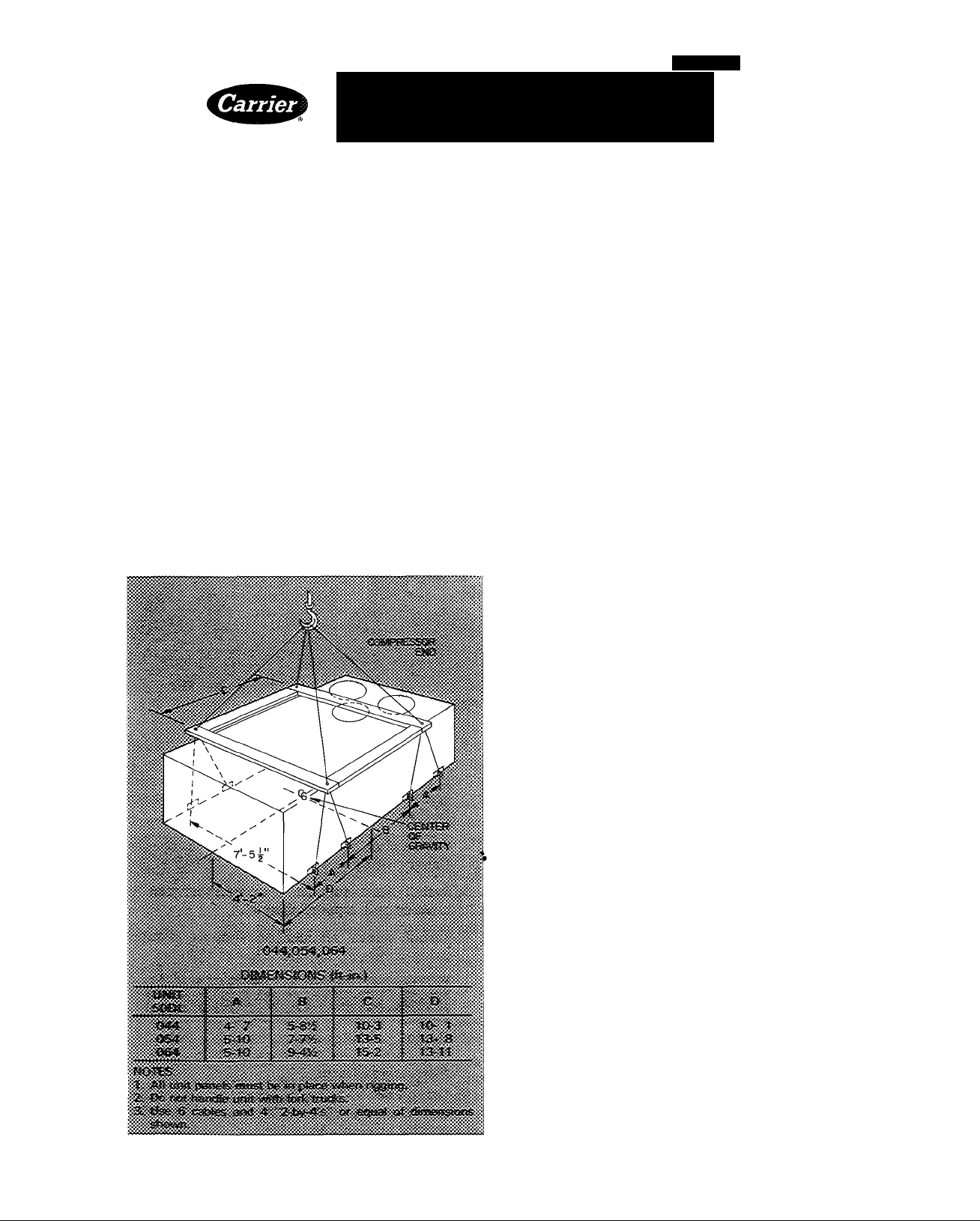
Rigging and Unit Placement — Inspect unit for
transportation damage. File claim with transporta
tion agency. Do not remove shipping skid until unit
is ready to be set in final location. Do not drop unit;
keep upright. Use spreader bars over unit to prevent
sling or cable damage. Rollers may be used to move
unit across a roof. Level by using unit frame as
reference. See Fig. 1 for additional information.
Unit weight is shown in Table 1.
Fig. 1 — Rigging Details
Units are designed to be hoisted only. However,
units with optional shipping skids may be moved
with a fork truck. Refer to Accessory Roof Curb
Installation Instructions for additional information
as required.
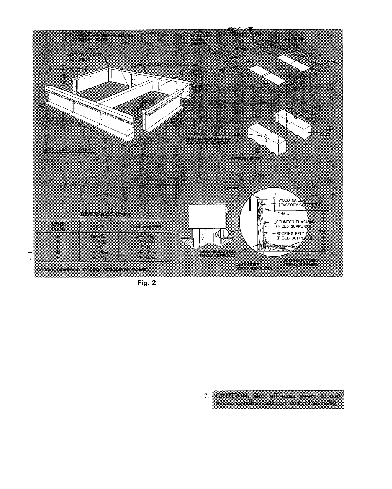
Roof Curb — Assemble and install as described in
instructions shipped with this accessory. Accessory
roof curb and information required to field fabricate
a roof curb of 2-in. x 14-in. planks is shown in Fig. 2.
Install insulation, cant strips, roofing and flashing as
required. For unit drains to function properly, curb
must be level or within tolerances shown in Fig. 3.
Roof Mount — Check building codes for weight
distribution requirements. Unit weight is shown
in Table 1.
Slab Mount — Provide a level concrete slab that
extends beyond unit cabinet at least 6 inches. Make
a slab 8 in. thick with 4 in. above grade. Use gravel
apron in front of condenser air inlet to prevent grass
and foliage from obstructing airflow.
Alternate Unit Support Methods — Where the
preferred curb or slab mount cannot be used,
support unit with sleepers on perimeter, using curb
support area. However, if sleepers cannot be used,
support long sides of unit (dimension “A,” Fig. 4)
with 4-in. X 4-in. pads equally spaced on each side.
Unit may sag if supported by corners only.
Positioning — Unit condenser air inlets and outlets
may be located in any compass direction since they
are not affected by wind. Provide clearances around
and above unit for airflow, safety and service
access (Fig. 4).
Do not install unit in an indoor location. Do not
locate air inlets near exhaust vents or other sources
of contaminated air.
Although unit is weatherproof, guard against
water from higher level runoff and overhangs.
Field-Fabricated Ductwork — Secure all ducts to
building structure. Use flexible duct connectors be
tween unit and ducts as required. Insulate and
weatherproof all external ductwork, joints and all
roof openings with flashing and mastic in accord
ance with applicable codes.
Carrier Corporation 1983 Form 50DL-1SI
Page 2
Roof Curb Dimensions
Insulate ducts passing thru unconditioned spaces
and cover with a vapor barrier.
Maintain one-in. minimum clearance between
supply air duct and any combustible material for at
least 3 ft of duct run from unit.
Unit is shipped set up for thru-the-bottom duct
connections. Ductwork openings are shown in
Fig. 4.
Economizer Section
ECONOMIZER HOODS INSTALLATION (Fig.
5) — The economizer mechanism and all electrical
connections are factory installed and adjusted
except as noted below. Hood assembly, outdoor air
inlet screens and required hardware are shipped
separately and must be field installed. Units have 2
hood assemblies.
Install economizer hoods and enthalpy control
as follows:
1. Loosen unit top panel sheet metal screws above
outdoor air inlet opening.
2. Assemble hood top panel, side panels and
support channel.
288
3. Insert hood flange between unit top panel flange
and unit. Slots are provided in hood flange to
clear sheet metal screws. Tighten sheet metal
screws. Apply RTV sealant to surfaces as shown
in Fig. 5.
4. Secure hood side panels to outdoor air opening
flanges, using screws provided.
5. Install hood support bracket(s) between U-
channel and support channel.
6. Install screen retainer on support channel,
using screws in the slots. Do not tighten.
8. Remove enthalpy control assembly from ship
ping location on horizontal deck in return air
filter compartment.
9. Using 4 no. 10-1/2 screws from envelope in con
trol assembly junction box, mount enthalpy
control assembly to inside of economizer hood
side panel nearest condenser section (Fig. 4).
Page 3
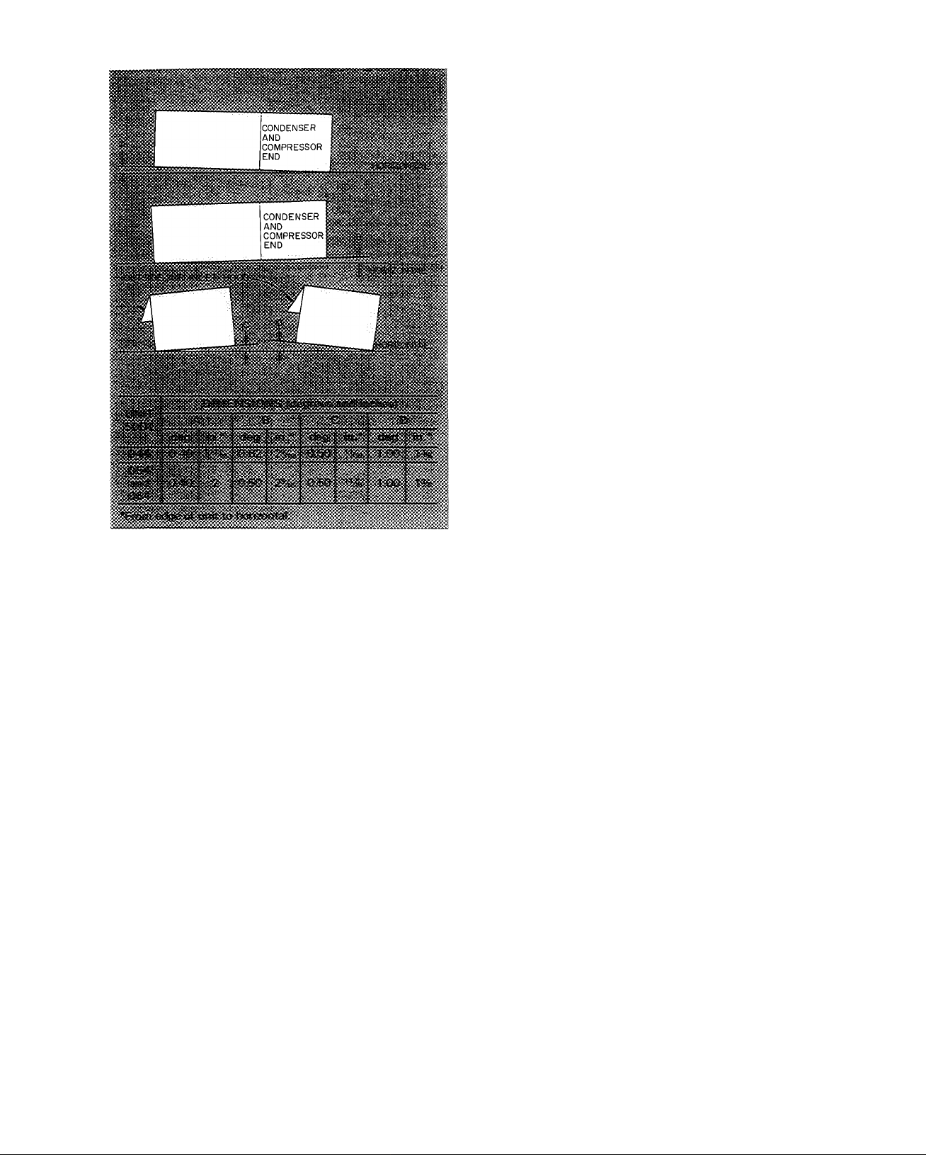
Fig. 3 — Unit Leveling Tolerances
10. Route the red and yellow wires thru knockout in
side plate. Wrap end of blue wire with electrical
tape. Using wire connectors from envelope in
junction box, wire enthalpy control assembly as
shown in Fig. 6. Use strain reliefs from envelope
on side plate and junction box.
11. Install outdoor air screens.
12. Push retainer snugly against screens and tighten
screws.
Exhaust Air Hood Installation — The optional
power exhaust package hood damper assemblies
and required sheet metal screws are shipped in the
compartment at right of indoor air fan motor com
partment. Using screws provided, install a hood
damper assembly over each exhaust air opening as
shown in Fig. 4. Power exhaust is applied only to
economizer units using bottom duct connections.
Exhaust fan and motor assembly is factory wired
and adjusted. Refer to Service, Power Exhaust
Air Fan Adjustment if required.
Indoor Air Fans — The fan belt and pulleys are
factory installed and adjusted. If required, adjust
as described in Service, Indoor Air Fan Adjustment.
Condensate Drains — See Fig. 4 for drain loca
tions. Condensate drain is open to atmosphere and
must be trapped. Install a trapped drain line at con
nection to be used. Trap must be at least 3in. deep
and made of flexible material or be installed to pre
vent freeze-up.
Condensate drain pan under unit is fitted with a
one-in. FPT coupling. A gasket is shipped taped to
this drain. Install gasket in unit basepan opening or
alternate opening on end of unit.
Field Power Supply — Unit is factory wired for
voltage shown on nameplate. The main power ter
minal block is suitable for use with aluminum or
copper wire. Units have circuit breakers for com
pressors, fan motors and control circuit. If required
by local codes, provide an additional disconnect
switch.
If an external electrical source is used, unit must
be electrically grounded in accordance with local
codes, or in the absence of local codes, with the
National Electrical Code, ANSI Cl-1978.
All field wiring must comply with National Elec
trical Code and local requirements.
Install conduit connector in unit basepan or side
panel openings provided as shown in Eig. 4. Route
power lines thru connector to terminal connections
in control box as shown in Fig. 8, 9 and 10.
Affix crankcase heater sticker to unit disconnect
switch.
Voltage to compressor terminals during com
pressor operation must be within voltage range
indicated on unit nameplate. Also, see Tables 2 and
3. Phases must be balanced within 2%. Contact local
power company for correction of improper voltage
or phase unbalance. Failure due to operation of unit
on improper line voltage or with excessive phase
unbalance constitutes abuse and may cause damage
to unit electrical components.
Field Control Wiring
STANDARD UNIT (WITHOUT ENERGY
MANAGEMENT OPTION) — Install a Carrier-
approved accessory electronic thermostat on a sub
base (or a transmitter on subbase if remote sensor is
used) per installation instructions included with the
accessory. Note that the subbase must be used oh
constant volume units without night setback. Locate
thermostat, or remote sensor, if used, in the condi
tioned space where it will sense average temperature.
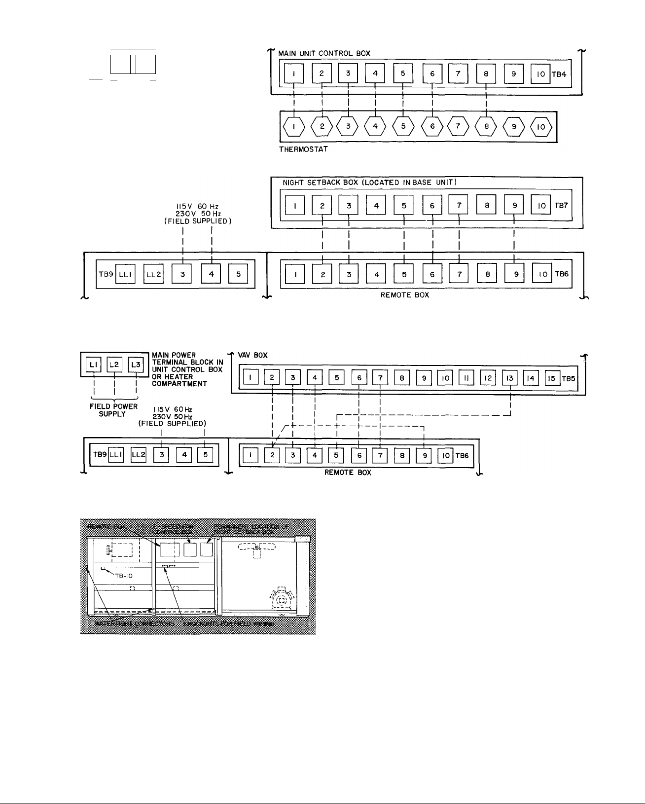
Route thermostat cable or equivalent single leads
of no. 18 AWG colored wire from subbase terminals
thru connector on unit to low-voltage connections
in main control box as shown on unit wiring dia
gram and in Pig. 8.
UNITS WITH ENERGY MANAGEMENT
OPTION — In addition to the standard control
box, units with Energy Management option are also
equipped with a remote box and a night setback
box. The remote box contains a 7-day time clock,
a bypass switch that can manually bypass the time
clock for up to 5 hours, 6 indicator lights and 2
terminal blocks for field wiring connections. Mount
this box remote from the unit in an indoor or
Page 4
Table 1 — Physical Data
UNIT 50DL
OPERATING WEIGHT (lb)
Base Unit
Economizer 225 250
Roof Curb 200 225
COMPRESSOR
Quantity...Type
Quantity Cylinders (ea)...Rpm 4 1750 4 6 1750
Capacity Steps (%) (Standard) 50, 100 60, 100
With Accessory Unloaders 25, 50, 75, 100
Capacity Steps (%) (Variable Volume)
With Electric Unloaders
REFRIGERANT CHARGE
System 1...System 2 (lb) 37 0 37 0 53 0 42 0
OUTDOOR AIR FANS
Quantity...Diameter (in.) 3 30 4 30
Nominal Cfm 21,000
Motor Hp...Rpm 1 1050
CONDENSER COIL
Rows...Fins/in. 3 158
Total Face Area (sq ft)
INDOOR AIR FANt
Quantity...Size (in.)
Maximum Allowable Rpm
Nominal Cfm
Standard Motor and Drive
Motor Hp
Motor Frame Size
Single Speed
Two Speed
Fan Pulley Pitch Diameter (in.)
Fan Pulley Bore I’Me
Single-Speed Motor Rpm
Two-Speed Motor Rpm
Motor Pulley Pitch Diameter (in.)
Pulley A
Pulley B
Resulting Fan Rpm
Single-Speed with Pulley A. .B
Two-Speed with Pullley A...B
Alternate Motor and Drive
Motor Hp
Motor Frame Size
Single Speed
Two Speed
Fan Pulley Pitch Diameter (in.)
Fan Pulley Bore I'Me I'Me
Single-Speed Motor Rpm
Two-Speed Motor Rpm
Motor Pulley Pitch Diameter (in.)
Pulley A
Pulley B
Resulting Fan Rpm
Single-Speed with Pulley A...B
Two-Speed with Pulley A...B
EXHAUST FAN MOTOR Quantity...Hp
EVAPQRATQR CQIL
Rows...Fins/in
Total Face Area (sq ft)
ELECTRIC RESISTANCE HEATERS
HeatikW
INDQQR AIR FILTERS
No. ...Size
Standard; 2-in Throwaway
Bag Type; 12-in. (Optional)
044
5406 6100
Serviceable, Hermetic
2 06E 2. .06E*
20, 40, 60, 80, 100
25, 50, 75, 100 20, 40, 60, 80, 100
Type 22; Controlled by Thermostatic Expansion Valve
Direct Driven, Propeller Type
28,000
1 1050
61 0
Belt Driven, Centrifugal Type
4 15x9
4 15x11
1300
16,000
20,000
15
254T
284T
10 6
1750
1750/1170
1750/1170
6 5
5 6 60
1073 925
1073/751
925/617
1073 ..991
1073/751
991/661
20
256T
286T
80 80
1750
1750/1170
1750/1170
5 3
5 6
1159 1225* 1159 1225
1159/773.
1225/817
«
1159/773.
1225/817
2 3 2 3
4 15
30 2
Open Nichrome Wire Elements with Multiple-Stage Control
See Electrical Data tables
27 16x25
21 16x25
6 12x24
6 24x24 7 24x24
054 064
6485
250
225
2 06E
6 1750
50, 100
16, 33, 50, 67, 83, 100
16, 33, 50, 67, 83, 100
81 0 81 0
4 30
31,000
1 1150
3 158
81 5
1300
20
256T 284T
286T
106
I’Me
1750
6 5
25t
284T
286T —
4 15.8
81 25
4 15x11
1450
24,000
25
286T
80
1750
1750/1170
56
60
1225 1312
1225/817.
1312/875
30t
286T
10 6
1750
5 3
5 6
4 15
35 4
9 20x25
7 12x24
1750
1750/1170
8 0
1321 —
1321/881
2 3
4 139
35 4
9 20x25
21 16x25
**
*Unit contains one 06EA250 and one 06EA275 compressor
tStandard fan motor supplied with standard fan drive pulleys and
belts; alternate fan motor supplied with alternate fan drive
pulleys and belts Other combinations are field supplied Pulley
A is installed in unit; Pulley B is shipped with unit (044 and 054).
288
JDue to large frame size, the 25-hp, 208-230-volt and 30-hp
motors are available in single speed only
**The 50DL064 alternate drive is supplied with Pulley A only
Page 5
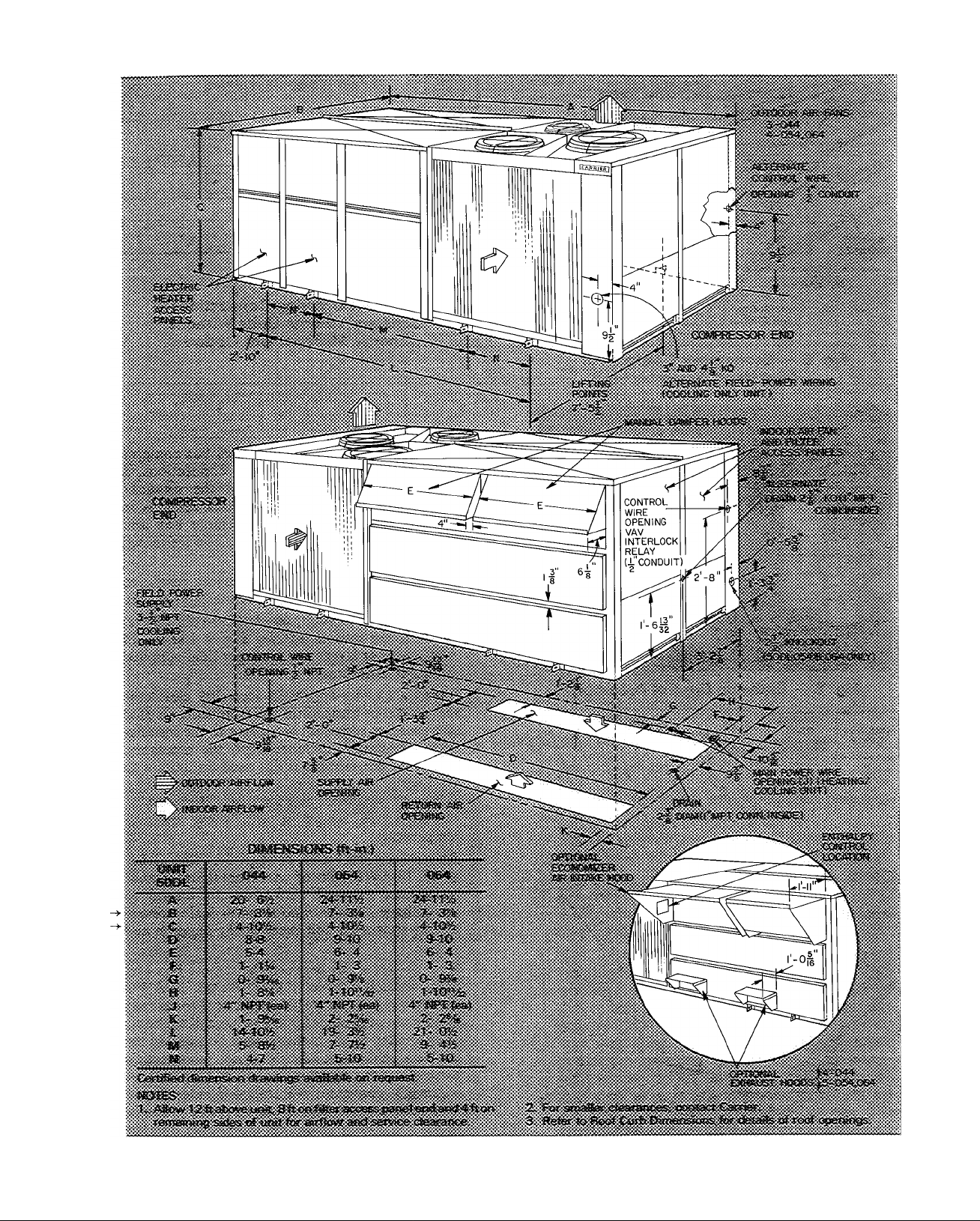
Fig. 4 — Base Unit Dimensions
5
288
Page 6
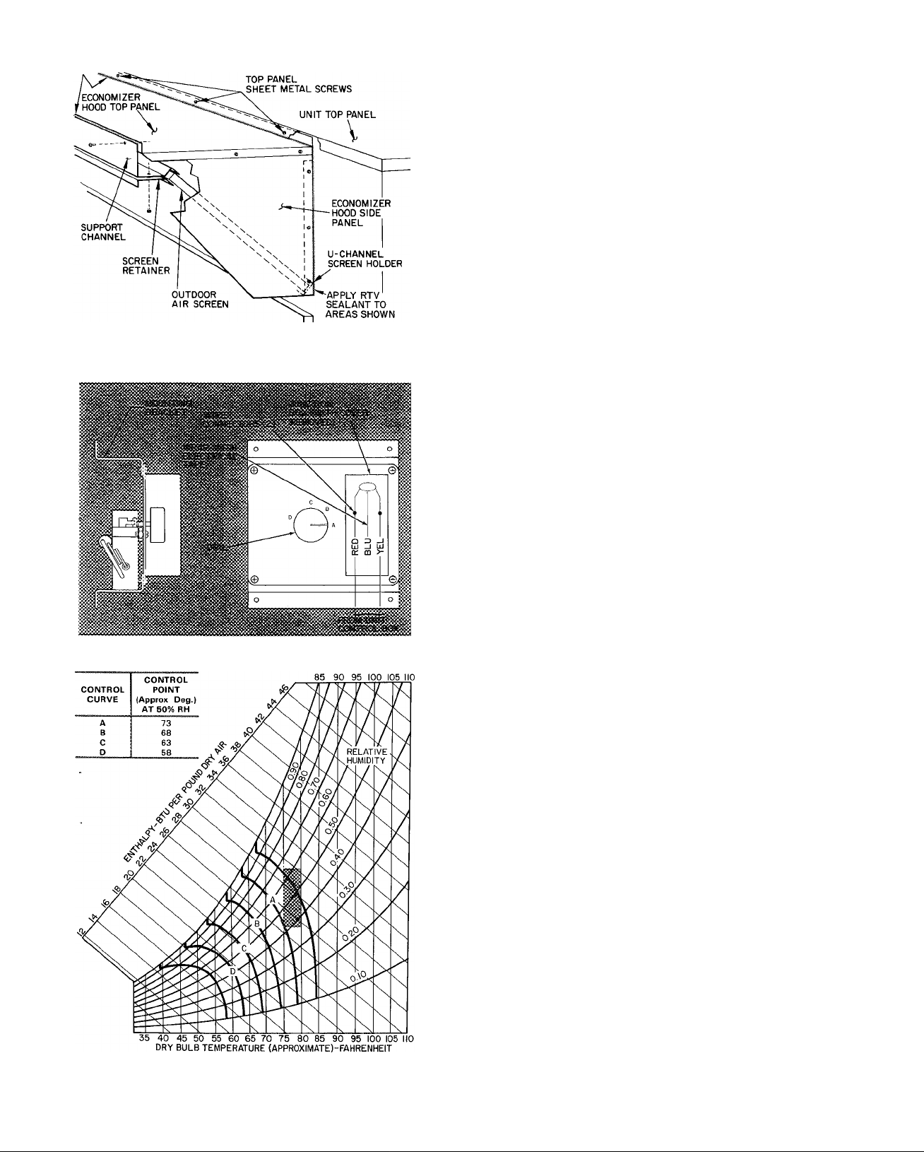
APPLY RTV SEALANT TO AREAS SHOWN
Fig. 5 — Economizer Outdoor Air
Inlet Hood Assembly
Fig. 6 — Enthalpy Control Assembly
Fig. 7 — Psychrometric Chart for
Enthalpy Control
MAIN POWER TERMINAL BLOCK IN UNIT CONTROL
BOX OR HEATER COMPARTMENT
^
FIELD POWER
SUPPLY
THERMOSTAT SUBBASE
NOTE Thermostat subbase required.
Fig. 8 — Field Wiring Connections
Constant Volume Units Without
Energy Management Option
TB4 MAIN CONTROL BOX
I I
weathertight space. The night setback box contains
a terminal block for field wiring connections, a
morning warmup thermostat and the setback/
setup module. The night setback box remains in
the unit. Shipping locations of remote box and
permanent location of night setback box are shown
in Fig. 11.
1. Remove remote box and mount in a restricted
access area (indoors or in a weathertight space).
2.
Run separate 115-volt, 60-Hz (230-volt, 50-Hz)
power to the remote box per Fig. 9. Use no. 14
AWG wire or larger and a proper field-supplied
electrical connector.
Install a Carrier-approved accessory electronic
thermostat or transmitter if remote sensor is used
(subbase not required) according to the installa
tion instructions included with the accessory.
Note that the subbase is not used on units with
the Energy Management option. Locate the ther
mostat or remote sensor, if used, in the condi
tioned space where it will sense average
temperature.
Route thermostat cable or equivalent single leads
of no. 18 AWG eolored wire from thermostat or
transmitter terminals thru connector on unit to
low-voltage (TB4) connections in main control
box as shown on unit label wiring diagram and
in Fig. 9.
4.
Run 24-volt wires between the remote box and
night setback box per Fig. 9. Use no. 18 AWG
wire for lengths up to 100 feet. Local codes may
dictate use of conduitfor low voltage. Knockouts
are provided in the night setback box and in the
fan deck separating heating section from section
containing the night setback box (Fig. 11). A
watertight connector is installed in side of unit.
Two rubber grommets are taped inside the night
setback box. Use grommets in knockouts in fan
deck and night setback box.
288
Page 7
MAIN POWER TERMINAL
L2
L3
~r~
NOTE Subbase not used
I
I I
FIELD POWER
SUPPLY
BLOCK IN UNIT CONTROL
LI
BOX OR HEATER
COMPARTMENT
Fig. 9 — Field Wiring Connections
Constant Volume Unit With Energy Management Option
Fig. 10 — Field Wiring Connections for 50DL VAV
Fig. 11 — Shipping Location — Remote Box
UNITS WITH VARIABLE VOLUME OPTION
— Units do not use room thermostats or sensors.
In addition to the main control box, units are
equipped with a remote box and a variable volume
box. Remote box is described above (Units With
Energy Management Option). The variable volume
box (Fig. 12) contains a microprocessor, a morning
warmup thermostat, a time-delay relay, 3 unloader
relays, an interlock relay, a night relay, a day relay
and a terminal block for field wiring. Shipping loca
tion of remote box is shown in Fig. 11.
1. Remove the remote box and mount in a restricted
access area (indoors or in a weathertight space).
2. Run separate 115-volt, 60-Hz (230-volt, 50-Hz)
power to the remote box per Fig. 10. Use no. 14
AWG wire or larger and proper electrical con
nector (field supplied).
3. Run 24-volt wires between remote box and
variable volume box per Fig. 10. Use no. 18 AWG
wire for lengths up to 100 feet. Run wire in con
duit to unit if local codes dictate. Knockouts are
provided in the variable volume box and the fan
deck separating heating section from section con
taining the variable volume box (Fig. 11). Water
tight connectors are installed in unit cornerpost
and side of unit. Two rubber grommets are
shipped taped inside variable volume box. Use
grommets in knockouts in fan deck and variable
volume box.
288
Page 8
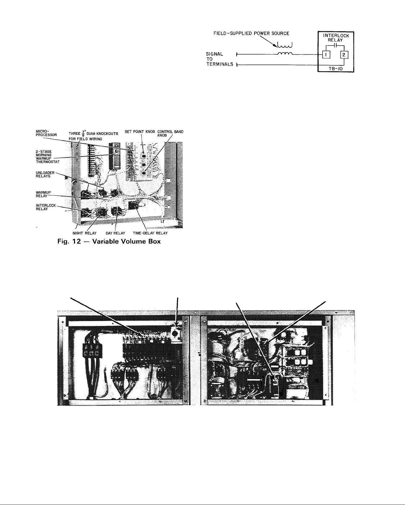
4. If the unit is equipped with electric heat, the room
terminals must be controlled to go fully open
when unit goes into heating. An interlock relay is
provided in the variable volume box. When unit
goes into heating, the interlock relay energizes
providing switch closure to open the room ter
minals. Field connections for the interlock relay
are terminals 1 and 2 of the terminal block (TB10)
located in upper left corner of electric heat sec
tion (Fig. 11).
Route field-supplied power wiring thru watertight
connector supplied in unit cornerpost. Make TBIO
connections as shown in Fig. 13.
Return Air Filters — Check that return air filters
are of the correct type and size and installed in unit
filter racks. Filter data is shown in Table 1. Do not
operate unit without return air filters.
Fig. 13 — Morning Warmup Interlock
Outdoor Air Inlet Screens — Outdoor air inlet
screens must be in place before operating unit.
Compressor(s) — Loosen compressor holddown
bolts until sidewise movement of the washer under
each holddown bolt head occurs. Do not loosen
completely as bolts are self-locking and will main
tain their adjustment.
Open the compressor discharge and suction
service valves. Replace and tighten valve caps to
prevent leaks.
Liquid Line Service Valve — Open the liquid line
service valve. Replace and tighten valve cap to
prevent leaks.
Low Ambient Compressor Lockout (Fig. 14) —
All units are equipped with an adjustable low
ambient lockout thermostat to lock off the compressor(s) at low outdoor air ambients. Thermostat
is located in the main control box. Setting will
depend on specific installation but should be
approximately 50 F on VAV units and 55 F on
constant volume units.
Convenience Outlet — All units are equipped
with a 115-volt convenience outlet for handling
small power load or service light. See Fig. 14.
CIRCUIT BREAKERS CONVENIENCE OUTLET LOW AMBIENT LOCKOUT
Fig. 14 — Control Box
THERMOSTAT
LOGIC PANEL
Page 9

Table 2 — Electrical Data — 5ODL044 and 054
MODEL
NOMINAL
VOLTS-PH-HZ
50DL044
208/230-3-60
50DL044
460-3-60
50DL044
575-3-60
50DL054
208/230-3-60
50DL054
460-3-60
50DL054
575-3-60
VOLTAGE
RANGE NO. 1 NO 9
Min Max
187
414 508
518 632
187 254
414
518
COMPR
RLA LRA RLA
254
80 345 80
37 173 37
30 120
117 506
508 53
632 42 5
30
78 5
253 36
176
28 6 120 4
COMPR
LRA
345
173
120
345
173
OUTDOOR
FAN
MOTORS
Qty FLA
76 20
3
(ea)
3 3
3
(ea)
2 7
3
(ea) 20
7 6
4
(ea)
33
4
(ea)
2 7
(ea)
INDOOR
FAN
MOTOR
Hp
15
15
20
15
15
15 46 0 3 11
15
20
20
20
20
15 21 0
15 21 0 3 4 8
20
15 21 0
15 21 0
20
15 21 0
15 21 0
20
20
20 27 0
20
15 17
15 17 3
20 22
20
20
25
20
20
25 75
20 60 3 11
20
25
25
25
25
20 27
20 27
25 34
20 27
20
25 34
20
20
25 34
25
25 34
25 34
20
20
25
25
EXHAUST
FAN
MOTOR
FLA
46 0
Hp
— —
FLA
46 0 3
60 0
—
46 0
—■ — 45/54 9
46 0 —
60 0 3 11
11 — —
—
—
HEATERS
kW
—
—
60/73 2
— —
45/54 9
3 11
46 0
60 0
60 0
— —
—
60/73 2
45/54 9
_
60/73 2 166/184
60 0 3 11 45/54 9 125/184
60 0 3 11
60/73 2 166/184
— — — —
— —
—
27 0
27 0 3
27 0
27 0
27 0 3 4 8
22 —
60
60 3 11
75
60
60
— — —
—
—
4 8
4 8
3
3
48 73 2 92
—
— —
4 8
3
54 9 69
—
73 2 92
— —
54 9 69
54 9 69 121
73 2 92
54 9 69
73 2 92
_ __
3 9
—
3 3 9
_
—
—
— — —
—
—
—
—
3 11
— —
— — 101
—
—
— —
60/73 2 166/184
75/91 5
— —
—
60/73 2 166/184
60 3 11
—
75
— —
75
75 3 11
75 3 11
75/91 5
—
60/73 2 166/184
75/91 5
60/73 2 166/184
75/91 5
— — — —
3 48
—
—
__
—
— —
27
3
27 3
27 3
34
22 0
48
48 73 2 92
48 91 5 115
—
—
—
—
3
48 73 2 92
3
48 91 5 115 187
—
—
22 0 3 3 9
— —
27 0
27 0 3 3 9
—
— —
73 2 92
91 5
— — 158
73 2 92
91 5 115 187
— —
— —
—
— —
FLA
—
—
125/138
166/184
MCA
249
271
263
249
265/288
285
125/138
166/184
125/138
271
271/288
263
283/305
285
285/305
115
124
121
115
142
130
124
142
149
130
149
93
—
—
—
98
106
312
334
327
312
208/230
335/363
349
334
208/230
335/363
327
208/230
354/382
349
208/230 354/382
—
141
151
148
149
115 178
151
178
158
158
113
121
—
118
126
ruvvcn
SUPPLY
MOCP*
300
350
300
300
350/350
350
350
350
350
400
350
400
150
150
150
150
175
150
150
175
175
200
175
200
110
125
125
125
400
450
400
400
400/450
450
450
450
450
500
450
500
175
200
200
200
200
200
200
200
225
250
225
250
150
150
150
150
See Legend and Notes on page 10
Page 10

Table 3 — Electrical Data — 50DL064
MODEL VOLTAGE
NOMINAL
VOLTS-PH-HZ
50DL064
208/230-3-60
50DL064
460-3-60
Compr — Compressor
FLA — Full Load Amps
Hp — Nominal Horsepower
kW — Kilowatts
LRA — Locked Rotor Amps
MCA — Minimum Circuit Ampacity
MOCP — Maximum Overcurrent Protection
RLA — Rated Load Amps
*Fuse only.
NOTES (Tables 2 and 3)
1 All outdoor fan motors are single-phase motors
2 All heaters are 3-phase assemblies
3 Unbalanced 3-Phase Supply Voltage
Never operate a motor where a phase unbalance in supply volt
age is greater than 2% Use the following formula to determine
the % voltage unbalance
% Voltage Unbalance
100 X-
RANGE NO. 1
Min Max RLA LRA RLA LRA
187 254 119 506 119 506
414
LEGEND (Tables 2 and 3)
max voltage deviation from average voltage
COMPR
53
508
average voltage
COMPR
253 53
NO. 2
253
OUTDOOR
FAN
MOTORS
Qty FLA
6 6/6 0
4
4
30
INDOOR
FAN
MOTOR MOTOR
Hp
25 75
25 75
30 88
25 75
25 75
30
25 75 3
25
30
30
30 88 3
30 88 3
25 34
25 34 3 48
30
25
25 34
302540
25 34 3 48
30
30
30 40 3 48
30 40 3
EXHAUST
FAN
FLA
Hp
FLA
— —
—
11
3
— — — —
— —
— —
3 11
88
75 3
88
88
40
34
34334848
40
40
Example:
A B
Determine maximum deviation from average voltage
(AB) 457 - 452 = 5 volts
(BC) 464 - 457 = 7 volts
(AC) 457 - 455 = 2 volts
Maximum deviation is 7 volts
Determine % voltage unbalance
% Voltage Unbalance = 100 x - ~ = 1 53%
This amount of phase unbalance is satisfactory as it is below
the maximum allowable 2%
11 60/73 2
11
—
—
—
—
11
11
—
— — —
—
—
— —
— —
— —
—
—
48
Supply voltage is 460-3-60
“ 457
HEATERS
kW
—
60/73 2
75/91 5 208/230 370/382 500
_
75/91 5 208/230 392 500
60/73 2
75/91 5
60/73 2
75/91 5
—
— —
73 2
91 5 115 187 250
73 2 92
91 5 115 187 250
73 2 92 172 250
91 5 115 194 250
73 2
91 5
AB = 452 volts
BC = 464 volts
AC = 455 volts
FLA
—
—
166/184 370 450
_
166/184 392 450
166/184
208/230 383/398
166/184
208/230 405 500
—
92
92 181
115
Average Voltage =
POWER
SUPPLY
MCA
370 400
392
383 450
405 450
383
405 500
166 200
175 200
172 200
166 225
181
175
194 250
452 + 464 -r 455
1371
MOCP*
= 457
¿i
-gíítíf
450
500
500
200
225
250
START-UP
Constant Volume Units
COOLING (WITH OR WITHOUT ENERGY
MANAGEMENT OPTION)
1. Open compressor service valves. Make sure the
crankcase heater has been on for at least 24 hours
to remove liquid refrigerant from compressor
crankcase. Check compressor oil level. Oil sight
glass should be half full.
2. Be sure that the liquid line service valve is open
and that high- and low-side refrigerant service
ports are closed as applicable.
3. On units equipped with the Energy Management
option, move the COOL SETUP SELECT
jumper wire to the desired setting(5°, 8°, or 12°).
If cooling is not desired during the unoccupied
periods, move jumper wire from COOL SETUP
to COOL LOCKOUT. See Fig. 15.
4. Turn on power to unit. On standard units, set the
subbase selector switch to COOL. On units with
the Energy Management option, set the 7-day
time clock as required. Refer to 7-Day Time
Clock Adjustment. Check that compressor low
ambient lockout contacts and morning warm-up
contacts (on units with Energy Management
option) are closed.
10
Page 11

i
(A) HEATING SETBACK
Fig. 15 — Setback/Setup Module (Partial)
5. Remove cover from thermostat (or from trans
mitter if a remote sensor is used); note the red
diagnostic light-emitting diodes (LED’s). See
Fig. 16.
6. To call for cooling, move the thermostat or
transmitter cooling set point (blue lever) below
room temperature. Cooling LED on the righthand side of thermostat or transmitter should
begin to glow. Check the cooling effect at supply
duct outlets.If the mechanical cooling does not
come on, see Service, Electronic Component
Checkout.
7. Move the thermostat or transmitter cooling set
point above room temperature. The cooling
equipment should cycle off and the cooling
LED intensity should decrease to a faint glow
or go off completely. The economizer should
move to minimum position.
(B) COOLING SETUP OR LOCKOUT
To Shut Off Unit — For standard units, set the
subbase selector switch to OFF or set the cooling
temperature selector lever above room tempera
ture. For units with Energy Management option, set
the cooling temperature selector switch above
room temperature.
Do not shut off unit circuit breakers except
when unit is serviced. Crankcase heater is ener
gized only when unit power is on.
HEATING (Electric Heat Units)
1. Turn on unit power; set circuit breakers at ON.
2. On units with Energy Management option, posi
tion the HEAT SETBACK SELECT switch in
the setback/setup module to the desired position
(5°, 10°, or 15°). See Fig. 15.
3. Move the thermostat or transmitter heating set
point (red lever) above room temperature. The
HEATING
LEVER (RED)
COOLING
LEVER(BLUE)
COVER THERMOSTAT/TRANSMITTER
Fig. 16 — Electronic Thermostat/Transmitter (Without Subbase)
11
Page 12

heating LED on the left-hand side of thermo
stat or transmitter should begin to glow. Electric
heat should cycle on. Check supply duct outlets
for heat. If heating equipment does not cycle on,
see Service, Electronic Component Checkout.
4. Move the heating set point below room tempera
ture. The heating equipment should cycle off and
the heating LED intensity should decrease to a
faint glow or go off completely.
5. Return the heating and cooling set points to
desired settings and lock in place. On standard
units, return subbase switch to desired position.
On units with Energy Management option, an
adjustable morning warmup thermostat is used
to hold dampers closed until return air reaches
the setting on the thermostat located in the
night setback box.
To Shut Off Unit — Standard units, set the subbase
selector switch to OFF or set the heating tempera
ture selector lever below room temperature. For
units with Energy Management option, set the heat
ing temperature selector switch below room
temperature.
AUTOMATIC CHANGEOVER — Standard units
automatically switch from heating to cooling mode
when the subbase selector switch is set at AUTO,
and the temperature of the conditioned space rises to
the cooling selector lever setting. When the tempera
ture of conditioned space falls to heating selector
lever setting, the unit automatically changes from
cooling mode to heating mode.
The thermostat and unit are so connected that
cooling and heating systems do not operate
simultaneously.
On units with Energy Management option, with
dual set point thermostat or transmitter, changeover
is also automatic. There is a minimum 3 F deadband
between the heating and cooling set points.
ECONOMIZER OPERATION — If unit is
equipped with modulating outdoor air control
(economizer), set enthalpy control (Fig. 4 and 6) at
“A.” Unit capability to integrate economizer with
.mechanical cooling allows for a higher changeover
point than conventional economizer systems. Be
cause of this, outside air is desired whenever its
enthalpy (total heat content) is below return air
enthalpy. Typical return air conditions, shaded
portion of Fig. 7, indicate that setting “A” should
be used for maximum operating economy.
OPERATING SEQUENCE WITH ECONO
MIZER (without Energy Management option)
using thermostat with subbase.
Cooling — System switch set at AUTO, or COOL,
fan switch at ON or AUTO, (indoor air fan runs
intermittently). Thermostat set at desired setting.
When thermostat calls for cooling and outdoor
air enthalpy is below setting of enthalpy controller.
the economizer modulates open. (If outdoor air
enthalpy is above enthalpy set point, the outdoor
air dampers remain at minimum position.) Econo
mizer acts as the first stage of cooling, providing
“free cooling” with outside air. If outside air alone
cannot satisfy the cooling requirements of condi
tioned space, economizer cooling is integrated
with mechanical cooling.
Compressor(s), working simultaneously with
economizer, will come on in stages to meet the
cooling load.
As the conditioned space temperature approaches
the thermostat’s cooling set point, stages cycle off,
last stage first. After all stages of mechanical cool
ing are off, economizer modulates to minimum
position.
During the cooling cycle, a discharge air sensor
senses discharge air temperature. If discharge air
temperature drops below 62 F, economizer starts
to modulate toward minimum position. At 50 F dis
charge temperature, the economizer will be at mini
mum position.
Heating — System switch set at HEAT or AUTO.,
fan switch at ON or AUTO., thermostat set at
desired setting. When thermostat calls for heating,
one or 2 stages of heat energize to satisfy heating
demand.
As space temperature approaches the heating
temperature set point, heating stages cycle off.
During heating, economizer is limited to the
minimum position to provide outdoor air for
ventilation requirements.
OPERATING SEQUENCE WITH ECONO
MIZER AND ENERGY MANAGEMENT option
(using electronic thermostat or transmitter).
Clock in remote control box switches controls to
OCCUPIED mode. Indoor air fan runs continually
while in OCCUPIED mode.
If return air temperature is below the adjustable
setting of morning warmup thermostat, outdoorair dampers remain closed.
When return air temperature goes above setting
of morning warmup thermostat, economizer goes
to adjustable minimum position.
When thermostat calls for cooling and outdoor
air enthalpy is below setting of enthalpy controller,
economizer modulates open. (If outdoor air en
thalpy is above enthalpy set point, economizer
remains at minimum position.) The economizer acts
as the first stage of cooling, providing “free cooling”
with outside air. If outside air alone cannot satisfy
cooling requirements of the conditioned space,
economizer cooling is integrated with mechanical
cooling.
Compressor(s), working simultaneously with
economizer, will come on in stages to meet the
cooling load.
12
Page 13

m
As the conditioned space temperature approaches
the thermostat’s cooling set point, stages cycle off,
last stage first. After all stages of mechanical
cooling are off, economizer modulates to minimum
position.
During the cooling cycle, a discharge air sensor
senses discharge air temperature. If discharge air
temperature drops below 62 F, the economizer
modulates toward minimum position. At 50 F dis
charge temperature, the economizer will be at mini
mum position.
At the end of the DAY (OCCUPIED) mode on
the clock, unit controls enter the NIGHT (UN
OCCUPIED) mode. Economizer closes. Indoor air
fan runs only on a call for heating or cooling. Tem
perature controls go into HEATING SETBACK,
COOLING SETUP or COOLING SHUTDOWN
mode.
HEATING SETBACK is field selectable at the
unit for 5°, 10°, or 15° below set point on room
thermostat.
COOLING SETUP is field selectable at the unit
for 5°, 8°, or 12° above set point on room
thermostat.
During the UNOCCUPIED mode, unit continues
to use economizer cooling first and then integrates
economizer cooling with mechanical cooling to
meet cooling requirements.
A 5-hour bypass timer is located in the remote
control box to provide air conditioning during
normally unoccupied hours.
TWO-SPEED INDOOR FAN OPTION — Table 1
lists the 2-speed indoor fan motor hp, frame size and
shaft diameter. Due to the larger frame size, the
208/ 230-volt, 25-hp motors and all 30-hp motors are
available in single speed only.
The 2-speed motors are 2 winding (4 pole/6 pole)
design, with speeds of 1750/1170 rpm. Indoor fans
automatically operate at low speed until high speed
is necessary to maintain comfort conditions. No
field wiring or adjustment is necessary.
COOLING mode sequence of operation is out
lined in Table 4.
In HEATING mode, the indoor fan operates at
low speed for ventilation only, and operates at high
speed during active heating. A 2-heat/4-cool logic
panel provides the necessary fan control.
The circuit breakers, contactors, and relays re
quired for 2-speed motor control are located in the
2-speed indoor fan motor control box (Fig. 17).
POWER EXHAUST OPERATION — Units have
an auxiliary switch located on the damper motor.
This switch is factory set to prevent the power
exhaust fans from operating when the economizer
damper is less than 30% open.
If other than factory setting is desired, adjust
as follows:
Table 4 — Two-Speed Indoor Air Fan
Staging; Cooling Mode
ECONOMIZER COOLING (Enthalpy Permitting)
OPERATING
CONDITION
NO CALL FOR COOLING
(Ventilation Air)
CALL FOR
MINIMUM COOLING
STAGE 1 OF
LOGIC PANEL
(Economizer Cooling)
STAGE 2 OF
LOGIC PANEL
(Integrated Econ/Mech
Cooling)
STAGE 3 AND 4
OF LOGIC PANEL
(Integrated Econ/Mech
Cooling)
SPEED
ECONOMIZER
FAN
Low
Low
High Full Open
High
High Full Open
DAMPER
POSITION
Minimum
Position
Modulating
Between
Min and
Full Open
Full Open
COMPRESSOR
OPERATION
Off
Off
Off
Compr 1
Compr 1 and 2
MECHANICAL COOLING
(Enthalpy Not Permitting Economizer Cooling)
ECONOMIZER
OPERATING
CONDITION
NO CALL FOR COOLING
(Ventilation Air)
STAGE 1 OF
LOGIC PANEL
STAGE 2 OF
LOGIC PANEL
STAGE 3 OF
LOGIC PANEL
STAGE 4 OF
LOGIC PANEL
INDOOR FAN
FAN
SPEED
Low
Low
Low
Low
High
DAMPER
POSITION
Minimum
Position
Minimum
Position
Minimum
Position
Minimum
Position
Minimum
Position
REMOTE CONTROL PANEL
COMPRESSOR
OPERATION
Compr 1
Compr 1 and 2
Compr 1 and 2
Off *
Off
Fig. 17 — Two-Speed Fan Control Box
Location
NOTE: Adjustment does not require running the
motor.
1. Motor must be in the fully closed position.
2. Referring to Fig. 18, take off “C” clip and drive
bracket. Remove screws at 4 corners of housing.
Pull off return spring housing.
3. Remove spring on motor shaft.
4. Adjust switch as shown in Fig. 19.
5. After adjustment, replace spring on motor shaft
and reassemble return spring housing.
13
Page 14

Fig. 18 — Removing Return Spring
Mechanism
STARTING POSITON
NOTE POSITION
OF RED DOT
CENTERLINE
Each adjustment mark repre
sents 10 degrees of motor rota
tion Use marks and center of
cam roller as adjustment guide
Red dot will be to right of centerline if switch is properly adjusted
Fig. 19
Adjusting Switch Make and
Break Points
ADJUST CAMS
OPERATIONAL
Loosen operational cam adjust
ment screw Rotate both cams
clockwise the number of de
grees motor must travel before
switch makes Tighten screw
CAPACITY CONTROL, HEATING — Stages 1
and 2 of heaters are controlled by heating relays
HRl and HR2, respectively. Using a suitable
ammeter, check heater current draw for heating
assemblies or elements. When checking secondstage heater operation, be sure heating thermostat
is set high enough to activate second-stage heaters.
Also, check operation of outdoor air thermostats if
additional staging is provided.
Modu-Pac® Variable Volume Units — Units
suitable for use with Modu-Pac variable air volume
systems (i.e. Carrier 37 Series terminal units) are
equipped with electric unloaders on the no. 1 com
pressor and hot gas bypass on the no. 1 refrigerant
system.
Before starting unit, open compressor service
valves and liquid line shutoff valve. Be sure com
pressor crankcase heaters are on and crankcase oil
level is half full. See Compressor and Crankcase
Heaters as applicable.
CONTROL SEQUENCE CHECKOUT
1. Turn on unit main power supply. Be sure unit is
ready to operate. Turn off compressor circuit
breakers.
2. Set the control band knob (Fig. 12) on micro
processor to 8° (50DL044) or 6° (50DL054,064).
3. If unit is not in DAY (OCCUPIED) mode, turn
on unit by overriding time clock with manual
bypass switch on remote box cover.
4. To check for cooling, turn set point knob
(Fig. 14) on microprocessor to 40 F. As cor
responding stage of cooling come on, the LED’s
should glow. Indicator light, located on remote
box cover, should also be lit.
5. Turn set point knob on microprocessor to 90 F.
The LED’s on microprocessor should go out as
corresponding stages turn off (providing ambient
temperature is below 90 F).
6. To check for heating on units with electric heat,
set morning warmup thermostat (Fig. 12),
located in variable volume box, to its maximum
position. If return air temperature is below the
set point, first stage of heat should come on. The
outdoor dampers should be tightly closed. Light
marked HEATING on the cover of remote box
should come on. NOTE: If unit has been in cool
ing mode, it will be necessary to shut off unit
power momentarily in order to check out heating
mode; once unit goes into cooling mode, a hold
ing relay locks out heating mode.
7. The morning warmup thermostat is a 2-stage
device. When first stage is satisfied, control shuts
down electric heat (if used). An adjustable dead
band of 3F to 10 F exists between first and
second stage. In the deadband zone, indoor air
fan runs but cooling mode will not begin until
return air temperature exceeds adjustable set
point of the second stage. Note that the difference
between heating and cooling set points will
always be 3 F to 10 F.
8. When checkout is complete and unit operation is
satisfactory, turn off bypass switch, position the
set point knob on microprocessor to desired
setting (approximately 55 F) and replace all
unit panels.
ECONOMIZER OPERATION — Refer to Con
stant Volume Units, Economizer Operation.
7-DAY TIME CLOCK ADJUSTMENT
Setting ON and OFF Times (Fig. 20) — NOTE:
14 trippers (7 sets, one set for each day) are included.
If more than 7 ON-OFF operations per week are
required, additional trippers are needed.
1. To set ON (OCCUPIED) time, slip the ON
tripper over edge of time dial and position at
desired day of the week and time of the day (AM
or PM). (When switch is turned on, normally
open contacts close and normally closed con
tacts open.)
14
Page 15

Fig. 20 — Setting the 7-Day Time Clock
NOTE: Dial turns clockwise when power is
connected and time clock is operating.
2. Hold tripper firmly against the edge of dial and
tighten knurled screw by hand. (Do not use
pliers.)
3. To set OFF (UNOCCUPIED) operation, use
OFF tripper and repeat steps 1 and 2, setting
the time desired for the switeh to turn off.
(Normally open contacts open and normally
closed contacts close.)
4. Time cloek can be set for up to 3 ON-OFF oper
ations per day or 21 per week. To omit operation,
do not place trippers on the dial for that day(s).
NOTE: Minimum time from an ON operation to an
OFF operation is 3-1/2 hours.
Minimum time from an OFF operation to an ON
operation is 3-1/2 hours (limited by the width of the
trippers which cannot be set closer).
Setting the Time of Day (Fig. 20)
1. Apply power to timer motor.
2. Turn time dial clockwise until the TIME pointer
is aligned with correct time and day. Do not
turn time dial counterclockwise and do not
move the TIME pointer.
Time clock has a spring wound carryover me
chanism to keep timer on schedule during power
failure up to 10 hours. When power is restored,
mechanism automatically rewinds.
VARIABLE VOLUME OPERATING SE
QUENCE (with accessory electric heat) — Clock
in remote control box switches controls to DAY
(OCCUPIED) mode. Indoor air fan runs for one
minute before any other control can function. (This
allows sensing of unit discharge air to start from the
conditioned space ambient rather than initial unit
ambient.)
If return air is below adjustable set point of first
stage of the morning warmup thermostat, heaters
energize. Outdoor air dampers remain elosed.
Normally open contacts in base unit override the
field-supplied VAV terminal controls and room ter
minals remain open during heating.
When first stage of morning warmup thermostat
is satisfied, heaters shut down, indoor air fan runs
eontinuously and outdoor air dampers remain
closed.
When conditioned space temperature rises to
adjustable set point of second stage of morning
warmup thermostat, unit switches to COOLING
mode. Outdoor air dampers go to at least the mini
mum position. (Once the unit has gone into cooling
mode, heat cannot come on during OCCUPIED
time period set on the clock.)
If outdoor air enthalpy is below setting of
enthalpy controller, economizer modulates open.
(If outdoor air enthalpy is above enthalpy set
point, economizer remains at minimum position.)
Economizer acts as first stage of cooling, providing
“free cooling” with outside air. If outside air alone
eannot satisfy cooling requirements of the condi
tioned space, economizer cooling is integrated with
mechanical cooling.
Compressor(s) will start, stop, load and unload
and economizer will modulate to maintain an
average discharge air temperature. If outside air
temperature drops below the adjustable setting
(normally 50 F) of the low ambient lockout, the
compressor(s) will shut down.
At end of DAY (OCCUPIED) mode on the clock,
unit enters the NIGHT (UNOCCUPIED) mode.
The outdoor air damper closes and indoor fan and
compressors shut down.
If a field-supplied night thermostat is installed
in the conditioned space, indoor air fan runs only on
a call for heating or cooling. Dampers open only on
a call for cooling. On a call for cooling, economizer
cooling occurs first and then integrates with me
chanical cooling to meet the cooling requirement.-
A 5-hour, manual bypass timer is provided in
remote control box. This timer, when manually
set by building occupant, overrides the UN
OCCUPIED mode and places unit in OCCUPIED
mode for up to 5 hours.
Constant and Variable Volume Units
TIME GUARD® CIRCUIT — Timer sequence
for a particular unit depends on unit and com
pressor arrangement. The Time Guard device pro
vides a delay in compressor start-up after thermostat
closes. On normal unit start-up, outdoor air fans
energize 15 seconds before the compressor. If com
pressor shutdown is due to satisfied thermostat or
automatic resetting of a safety device, the com-
15
Page 16

pressor automatically restarts after a 5-minute inter
val. If compressor shutdown is due to tripped over
loads, the circuit breakers must be manually reset
before compressor will start.
Timer (Time Guard®) for second compressor has
a 6-minute interval to prevent compressors from
starting simultaneously.
Refer to unit label diagram for specific timer
sequence.
CRANKCASE HEATER — Unit main power
supply must remain on to provide crankcase heater
operation. Crankcase heater in each compressor
keeps oil free of refrigerant while compressor is off.
HEAD PRESSURE CONTROL — Each unit has a
fan cycling thermostat to shut off 2 outdoor fan
motors at 55 F. This permits unit to operate with
correct condensing temperatures down to 35 F out
door air temperature.
SERVICE
Electronic Component Checkout
CONSTANT VOLUME UNITS
The checkout procedures in this section will
determine whether;
1. The logic panel is controlling the heating and
cooling equipment properly.
2. System components are correctly wired to the
logic panel.
Prior to checking out control circuit, establish
setting on the low ambient lockout thermostat.
Compressors will not start below this setting (cool
ing mode only). Recommended setting is approxi
mately 50-55 F.
NOTE: To complete the electronic component
checkout, a volt-ohmmeter (Simpson 260 is
recommended) is required.
LOGIC PANEL (Fig. 21)
1. Check that 24 VAC is supplied to logic panel.
Connect meter to terminals TR.
2. Check thermostat supply voltage at STAT ter
minals 1 and 2. Reading should be 20 VDC.
3. Remove thermostat supply wires from STAT
terminals 1 thru 5 on logic panel.
4. Set meter to volts AC scale equal to relay switch
ing voltage (50-volt scale for 24 VAC).
5. To simulate a call for cooling, jumper between
STAT terminals 2 and 4. Normally open Logic
Panel contacts (Cool 1 and 2) should close and
cooling equipment should cycle on.
6. Connect meter leads to the normally open cool
ing contacts 1 and 2 on logic panel. Meter should
Fig. 21 — Logic Panel
read zero if contacts have closed and contacts
are made.
If meter is reading zero and cooling equipment
has not cycled on, logic panel is not at fault.
7. To simulate a call for heating, jumper between
STAT terminals 2 and 5. Normally open logic
panel contacts (HEAT 1 and 2) should close and
heating equipment should cycle on.
8. Connect meter leads to the normally open heat
ing contacts on logic panel. Meter should read
zero if contacts have closed.
If meter is reading zero and heating equipment
has not cycled on, logic panel is not at fault.
9. Replace thermostat wiring to terminals 1 thru 5.
DISCHARGE SENSOR
1. Set resistance on meter to R x 100.
2. Disconnect lead from SENSOR terminal T1 on
logic panel.
3. Connect one meter lead to logic panel terminal T
and the other meter lead to the loose lead wire
from the sensor.
4. Meter readings depend on temperature. Dis
charge sensor readings should be between 1500
and 4500 ohms. See Fig. 22.
THERMOSTAT/TRANSMITTER (Fig. 16)
1. Set meter to 20 VDC scale.
2. Check for power to thermostat. Connect negative
(-) lead to terminal 1 and positive (+) lead to
terminal 2. Meter should read 20 VDC.
3. Connect the negative (-) lead to terminal 1 and
the positive (+) lead to terminal 4.
4. Slowly move the cooling lever below room tem
perature to simulate a call for cooling. Meter
16
Page 17

reading should gradually increase to about
16 VDC. (See Fig. 23.)
5. Move the cooling lever above room temperature.
Meter reading should drop to less than 2 VDC.
6. Remove the (+) meter lead from terminal 4 and
connect it to terminal 5.
7. Slowly move the heating lever above room tem
perature to simulate a call for heating. Meter
5000
4800
4600
4400
4200
4000
3800
3600
3400
3200
3000
2800
2600
2400
2200
2000
1800
1600
1400
1200
1000
800
600
400
200
N
L
____
\
^30 OOnAT 77F( >50
60 65 70 75 80 85 90 95 100
(16) (18) (21) (24) (27) (29) (32) (35) (38)
TEMPERATURE DEGREES F (DEGREES C)
Fig. 22 — Resistance Range of
the Discharge Sensor
'
reading should gradually increase to about
16 VDC. (See Fig. 23.)
8. Move the heating lever below room temperature.
The meter reading should drop to less than
2 VDC.
ECONOMIZER (Motor Operation) — Check to
see 115 V is at the economizer motor. Remove wire
from the W terminal on damper motor. Dampers
should go fully open.
Short between R-W on motorterminals. Dampers
should go fully closed.
Logic Panel Economizer Signal
1. Disconnect terminal W on logic panel.
2. Connect meter (2.5 VDC scale) with negative (-)
lead to R and the positive (+) lead to W.
3. Set thermostat for a call for cooling. Meter
reading should rise to 1.5 VDC. If thermostat
was already calling for cooling, reading will be
1.5 V when meter is connected.
4. Turn thermostat up so that no cooling is called
for. Voltage should fall from 1.5 VDC to 0.
Conduct the above test with air temperature at
the discharge sensor (located at unit air dis
charge) above 62 F. If air is below 50 F, there will
be no voltage signal. If air is between 50 F and
62 F, voltage will be in the same proportions.
VOLTAGES NECESSARY TO ACTIVATE LOGIC PANEL
HEAT STAGE
1
2
Differential: 63 +
VOLT DC
4 63 1
5 88
07 volts
COOL STAGE
2
Tolerance: i 25 volts
Fig. 23 — Thermostat/Transmitter
Output Voltage Ramps
VOLT DC
5 00
5 88
Cleaning — Inspect unit interior at the beginning
of each heating and cooling season and during each
season as operating conditions require. Remove unit
top panel(s) and/ or side panels as required to expose
unit interior.
EVAPORATOR COILS — Clean with a stiff
brush, vacuum cleaner or compressed air.
CONDENSER COILS — Clean with a stiff brush
or vacuum cleaner. When cleaning with compressed
air or low-pressure water or steam, guard against
damaging compressor wiring and nearby controls.
Condenser fan motor(s) is drip-proof but not
waterproof.
CONDENSER SECTION DRAIN — Check that
area under coil is clear and drains freely.
CONDENSATE DRAIN — Check and clean
annually at start of cooling season. In winter, keep
drain and trap dry or protect against freeze-up.
FILTERS — Replace filters at start of each heating
and cooling season or as often as necessary during
each season, depending on operating conditions.
Refer to Table 1 for type and size of filter used.
Filter access panels are shown in Fig. 4. Return air
filter tracks will accept 2 layers of 1-in. thick filters
if 2-in. filters are not available. Do not install bag
filters in standard filter tracks. Do not install
17
Page 18

standard filters or 2-in. high-efficiency filters in bag
filter tracks.
OUTDOOR AIR INLET SCREEN(S) -- Clean
screens with steam or hot water and mild detergent.
Do not use throwaway filter in place of these
screens. Loosen fastening-bracket screws and slide
out screens.
Lubrication
COMPRESSORS — Each compressor is charged
with correct amount of oil at the factory. Oil level
should be between bottom and mid-level of sight
glass when compressor is warm. Refer to 06D or
06E Compressor Service Manual if additional infor
mation regarding compressor lubrication system
is required.
FAN SHAFT BEARINGS — Charge each grease
fitting with a suitable bearing grease at least once a
year. Do not overlubricate.
FAN MOTOR BEARINGS — No relubrication of
outdoor air fan motors is necessary for first 2 to 5
years of use, depending on operating conditions.
Annually thereafter, open, clean and repack each
bearing with a suitable bearing grease.
Indoor air fan motor bearings should be cleaned
and repacked with a suitable bearing grease
annually after initial unit installation.
Power Exhaust Air Fan Adjustment (if fitted) —
Adjust belt tension so that 1/8-in. deflection at 5-to
8-pounds pressure between pulley centers can be
obtained. To change tension, loosen motor mount
ing bolts, reposition motor and tighten mounting
bolts. Tighten locknut and bolt under motor
mounting plate to secure in fixed position.
Outdoor (Condenser) Air Fan Adjustment
(Fig. 24) — Shut off unit power supply. Remove fan
guard and loosen fan hub setscrews. Adjust fan
height using a straight edge laid across venturi.
Tighten setscrews and replace rubber hubcap to
prevent hub from rusting to motor shaft. Fill hub
‘recess with permagum if hub has no rubber hubcap.
Damper Vent Position Setting
1. On constant volume units, adjust thermostat or
transmitter so there is no call for cooling. On
variable volume units, adjust set point knob on
microprocessor so there is no call for cooling.
The economizer dampers go to minimum
position.
2. Remove cap from vent adjustment screw on top
of damper motor terminal box cover.
3. Turn adjustment screw slowly until dampers
assume desired vent position. Do not manually
operate damper motor. Damage to motor will
result.
POWER FAILURE — Dampers have a spring re
turn. In the event of a loss of power, dampers close
until power is restored. Do not manually operate
damper motor. Damage to motor will result.
Fig. 24 — Outdoor Air Fan Adjustment
Refrigerant Charge — Amount of refrigerant
charge is shown on unit nameplate and in Table 1.
When charging refrigerant system, refer to Carrier
Standard Service Techniques Manual, Chapter 1,
Refrigerants. When adding a complete charge,
evacuate the system using standard evacuating pro
cedures and weigh in specified amount of refrig
erant. A charging chart (Fig. 25, 26, and 27) is pro
vided on unit control box door above compressor
and may be used (use of sight glass not required).
When using refrigerant liquid line sight glass to
charge system:
1. Install a jumper on the low-pressure switch if
required.
2. Operate unit with restricted condenser airflow
to achieve an operating discharge pressure of
about 375 psig.
3. Slowly add refrigerant until sight glass clears.
4. Remove jumper from low-pressure switch and
remove condenser air restriction.
Indoor Air Fan Adjustment — Fixed fan speeds
are set as shown in Table 1. If other than available
fan speeds are required, select field-supplied motor
or pulleys, using data from Tables 5 and 6, and
Fig. 28 and 29.
PULLEY REMOVAL — Pulleys are of the fixed
type and have taper-lock bushings. To remove, shut
off unit power. Loosen fan motor mounting plate
and remove belt. Relocate taper-lock bushing bolts
in removal holes to loosen bushing. Remove pulley
from shaft.
After reinstalling pulley and belt, check pulley
alignment and belt tension as described below.
PULLEY ALIGNMENT — Loosen fan shaft pulley
bushing and slide pulley along shaft. Make angular
adjustment by loosening motor mounting plate and
repositioning it as required.
BELT TENSION — Adjust belt tension by moving
motor back until only a slight bow appears in the
belts on the slack side of the drive while running
under full load. Secure motor. Recheck belt tension
after 24 hours of operation, adjust as necessary.
18
Page 19

Page 20

COMPRESSOR SUCTION PRESSURE
Fig. 27 — Charging Chart; 50DL064, System 1 and System 2
Table 5 — Indoor Air Fan Pulley Data
UNIT
50DL
MOTOR
FAN
PULLEY
RPM
No Grooves - Type - In.
i 991Ì3-3V-6.0 ! 3-3V-10.6 ! 3-3V-750 I3-3V-770
044 ! 1093 Ì4-3V-50 i 4-3V- 8.0 l’4-3V.710j 4-3yj^710
! 1039 Ì5-3V-4.75Ì 5-3V- 8.0 Ì5-3V-710 Ì
054 ^
1093 i s-3V-5.0 ! 5-3V- 8.0I5-3V-710
FAN
PULLEY
SINGLE
SPEED
BELT
NO.-SIZE
-------------------
0 Ì4-3V-710
TWO-
SPEED
BELT
NO - SIZE
mmmm
825 4 -3V- 5 6
991 4 -3V- 6 0
5-3V-475 5-3V- 80
1039
4 - 3V- 6 5 4-3V-106
1073
1093
064
5 -3V - 5 0
1159 5-3V-5.3 5-3V- 8.0
■ •iSSSewH
4 - 3V - 10 6 4-3V-750
4-3V-106 4 - 3V - 750
5-3V- 80
5-3V-710 5-3V-710
4 - 3V - 750
5-3V-710
5-3V-710 5 • 3V - 720
WW«?KSS¥Sw!
Shaded values indicate standard or optional pulley
available as shown in Physical Data table All other
are field supplied
•Three belts are required. 4 may be used if desired
tRemove one belt
20
4 - 3V- 750
4 - 3V - 770
4 - 3V - 770
5 • 3V - 720
combinations
combinations
Page 21

Table 6 — Indoor Air Fan Data
UNIT
50DL
054,
064
CFM
8,000 467 1 22 546 1 61 628
9,000 508 1 65 575
10,000
11,000
12,000 642 3 60 688 4 00 738 4 48 791 5 07 847 5 78 902
13,000 689 4 52 730 4 93
044
14,000
15,000 783 6 79 818 7 24 855 7 74
16,000 831 8 18
17,000 879
18,000 927 11 52 956
19.000
20.000
10,000
11,000 519 1 90 601 2 30 679 2 84 750
12,000 554
13,000 590 3 04
14,000
15,000
1 6,000
17,000
18,000 780 7 83 820 8 09
19,000
20,000 859 10 69
21,000
22,000 938
23,000 978 16 18
24,000 1018
0.20
Rpm Bhp Rpm
552
2 18 609
596
2 83 648
736
5 57
9 75 910 10 24 941
976
13 48
15 67
1024
487
1 47 577 1 89 659 2 40 733
2 42
627 3 76 684
664 4 59 716 4 87 775 5 34
703 5 54 750
741 6 62 785 6 88
819 9 19 857 9 45
12 35 932 12 62 967
898
14 18
18 36 1047 18 64 1076
0 40
Bhp
2 02 649 2 54
2 56 674 3 06
3.21 704 3 70
774
6 00
864
8 65 898 9 17 933 9 74 971
12 03
14 02
1003
16 23
1050
626 2 77 702 3 34
654
3 35
4 05
5 81
894
10 95
970 14 45 1003 14 78
16 45 1040
1008
0.60 0.80
Rpm
775
814
986 12 58 1016
1031
1076
724
749
803
833 7 28 886
865
898 9 81 943
932
EXTERNAL STATIC PRESSURE (in. wg)
Bhp
Rpm Bhp Rpm Bhp
2 12 705
5 41
6 49
10 78
14 59
16 82
3 92
4 58 813
6 24 860
8 47 914
11 30
12 96
16 78 1073
18 97
2 66 774
721
3 14 789 3 75 852
741
3 67
764
4 32
822
5 98 873
857 7 06
8 31
894
974 11 36
1059
1103
770 3 95
791 4 57 852
836 6 02
973 11 77
1005
1039 15 21
1108
1008
13 18 1048 13 83
15 21
1089
17 45
1131
2 99 802
3 42 817
5 25
6 90
7 88
9 01
10 31
1018 1241 1064
13 40 1047
1077
17 20
1109 17 72
19 38 1141
806
825 5 01 883 5 75
902 7 72
935 8 96
833 4 62
873 5 96
894 6 77
917 7 66
940
965 9 77
991 11 00
1
00
3 24
4 35 867
6 68 924 7 46
10 38
12 00 1044
15 86
18 12
3 60
4 09 879 4 76 935
5 23
8 66 993
13 99
15 76
19 88 1177
1.20 1.
Rpm Bhp
839 3 85
949
978
11 11 1050
1009
12 72 1081 13 51
14 54
1081
1119
16 58
18 84
1159
863 4 21 922
895
910 5 97 967 6 77
928 6 69 982
949
970
1016 10 62
1039 11 86
13 24
14 76 1134
1090
16 47
1118
1146 18 38
20 50 1214 21 26
40
Rpm Bhp
900 4 47
4 40 911
5 03 924
6 54
8 51
9 70 1022
5 35
7 52
8 47
9 49 1042
5 08 967
5 73
939
6 50
956 7 35
975
8 28 1025
997
9 35 1045
10 57 1067
11 93
1115 15 31 1150 16 17
1151
17 35
19 61
1189
4 86 977 5 58
5 42
952
6 08 1003 6 79
7 49
1000 8 32 1051 9 18
1021
9 27 1069 10 12
10 35 1089 11.21 1134
1064
11 51 1110 12 42
1087
12 78
1110 14 17
15 70
17 35
1159
1186
19.20 1226 20 20 1266 21 27
1.
60
Rpm Bhp
956
5 09
5 77
978
6 48
992
7 26
1008
8 17
9 15 1074^
10 23
11 47
12 86 1134
1092
1119 14 40
1183 18 19
6 11
989
1020 7 57
1035 8 35
1132
13 74
1155 15 14
1178 16 69
1201 18 37
1252 22 19
1.80
Rpm Bhp
1010 5 72
1020 6 46
1031
7 24
1043 8.06
1057
8 99
10 04
1091
11 17
1111
12 40
13 82
1159
15 40
1186
17 12
1217
19 10
1030
6 27
1041
6 88
1054
7 54
1069
8 33
9 21
1085
1100 10 11
1116 11 05
12 11
1155
13 33
1176
14 69
1197 16 16
1220 17 72
1243 19 42
1290 23 28
UNIT
50DL
Bhp — Brake horsepower
Rpm — Revolutions per minute
CFM 2.00 2.20 2.40
Rpm Bhp Rpm Bhp Rpm Bhp
6 37 1110 7 04 1155
1061
8,000
1070 7 15
9,000
10,000
11,000
1 2,000
1 3,000
044
14,000
1 5,000
1 6,000
1 7,000
18,000
19.000
20.000
10,000
11,000 1090 7 67 1138
1 2,000
13,000
14,000
15,000 1148
16,000
054,
1 7,000 1178
064
18,000
19,000
20,000
21,000 1260
22,000 1283 20 51
23,000 1306
24,000 1329 24 39
1081 8 01 1128
1091 8 89 1139 9 73
1105 9 84 1150
1120 10 93
12 12
1137
1155 13 40 1198
1176 14 80
1198 1641 1238 17 45
1224 18 18 1261 19 25
1078 6 91 1125 7 63 1169
1102 8 33
1116 9 12
1132 10 05 1175
11 03 1193
1162 12 03 1208 13 01
13 09 1222
1197 14 29 1239
1218 15 65 1258
1239 17 17 1279 18 18
18 79 1300
22 38 1344 23 52
EXTERNAL STATIC PRESSURE (in. wg)
2.60
Rpm Bhp
7 87 1164
1118
8 78
10 72
1165
11 82 1208 12 76
1181 13 08 1223 14 04
14 42
1217 15 85 1257
8 43 1181
1149
9 18
1161 9 94 1206
10 88
11 94
14 13 1266
15 31 1281 16 40
16 66 1297 17 72
19 85 1338
1321 21 63 1359 22 74
1367 25 55 1403 26 75
NOTES 1 Fan performance has deductions for unit casing losses, wet coil and clean standard filters
7 69 1201
8 57
1173 9 54
1184
10 57
1195 11 63
1240 15 44
16 93 1297
1277
18 54
8 35 1210
9 12 1225
1194
10 05 1237
10 83 1249
1219 11 75
1234
12 81
1251
13 99 1291
15 17 1307
1317
19 23 1354
20 90 1375 22 01
24 69
1380
2 Fan motor bhp is based on minimum voltages and 80 F air access motor
3 Consult physical data and indoor air fan pulley data.for appropriate motor and pulleysizes with
corresponding rpm
4 For rpm's outside of published data, field-supplied drive may be required
8 38 1245
1209
9 33 1252
1218 10 34
1228 11 43
1238 12 55
1250
13 72
1264
15 00
1280
16 48
18 03
9 10
9 90 1266
10 87
11 76
1260 12 64
1275 13 72
14 95
16 22
1322
17 51
1337
18 85
20 33
1395
23 84
1416
25 85
1438
27 98
2.80
Rpm
Bhp
9 09
10 08
1260
11 13
1269 12 25
1280 13 46
1291
14 70
1253
9 89 1293
10 70 1303 11 50
1278 11 64
1290
12 70
1302
13 60 1342
1315 14 66
1329 15 87
1347
17 25
1362
18 61 1400 19 72
1376
20 02
1392
21 50
1410 23 14
1431
24 99
3 00
Rpm Bhp Rpm
1332
10 71
1318 12 45 1356
1330 13 60
1354 15 63
1368 16 86
1384
1415 21 19
1430
1446
1342
1369 14 45 1405
14 61
1380
1392
1405 17 87 1441 18 89
18 25 1419 19 24
1437
22 73
24 35
3.20 3.40
Bhp Rpm Bhp
1371
11 52
12 34 1380 13 22
13 32 1393 14 19
15 62
1418 16 60
16 66
1429 17 73
20 80
12 37
15 27
21
Page 22

о
о
ю
Ю'
K)
I
Оо
—о
zS
—СМ'
Og
ИЛм'
СЛ
СО
CÛO
0_-'
>—t)
h-O
<-■
со
N
N
о
—^
N
\
N
К
\
N
N
N
N
N
N.
N .
''
V
-V,
N,
N
N
N
N
о
N,
\
V.
2
s
.
s
V
N,
N,
s. Ч
V.
N ,
V
Ч
"N
s
N.
\. ;
N.
Ч
3
5
Ч
#
X
X
ч
s
Ч
ib-
S
Ч
VX
яг
¿.с
S
IL
1
J
12n
s.
S
ч
s
V
Ч
с
S
'S N_
ч
X
N
\
iv-
Ч
V
\ 1
!.,
_
V
s
го
S.
X
.5
ю
МАХ RPM“ МОО MIN RPM' 800 INCR RPM' 100 MIN НР = 2 МАХ НР= 25
I
CFMdOOO S) (STD AIR)
Fig. 28 — 50DL044 Indoor Air Fan Data
22
t
Page 23

N)
(Q
to
(O
OI
o
Q
rO
cn
0)
3
Q.
O
3
^
Q. —
O °
■b O
CO
0>
3
U
Q)
CO
—)
o
TOTAL STATIC PRESSURE IN WG
0
TOTAL STATIC PRESSURE IN WG *10
-3
>
::o
Page 24

For replacement items use Carrier Specified Parts
Manufacturer reserves the right to discontinue, or change at any time, specifications or designs without notice and without incurring obligations.
#
Book 1
Tab
1b
Form50DL-1SI New
Printed in U S A
288
6-83 PC 111 Catalog No 565-020
 Loading...