

Page 1
50DF034
HEATING & COOLING
Installation, Start-Up and
Service Instructions
SAFETY CONSIDERATIONS
Installation and servicing of air conditioning
equipment can be hazardous due to system pressure and
electrical components. Only trained and qualified service
personnel should install, repair or service air conditioning
equipment.
Untrained personnel can perform basic maintenance
functions of cleaning coils and filters and replacing filters.
All other operations should be performed by trained
service personnel. When working on air conditioning
equipment, observe precautions in the literature, tags and
labels attached to the unit and other safety precautions
that may apply.
Follow all safety codes. Wear safety glasses and work
gloves. Use quenching cloth for unbrazing operations.
Have fire extinguisher available for all brazing
operations.
Single-Package Cooling Units
Alternate Unit Support Methods — Where the
preferred curb or slab mount cannot be used, support
unit with sleepers on perimeter, using curb support area.
However, if sleepers cannot be used, support long sides
of unit (dimension A, Fig. 4) with three 4-in. x 4-in. pads
equally spaced. U nit may sag if supported by corners only.
Positioning — Unit condenser air inlets and outlets
may be located in any compass direction since they are
not affected by wind. Provide clearances around and
above unit for airflow, safety and service access (Fig 4).
Do not install unit in an indoor location Do not locate
air inlets near exhaust vents or other sources of con
taminated air
Although unit is weatherproof, guard against water
from higher level runoff and overhangs.
A WARNING
Before performing service or maintenance operations
on unit, turn off main power switch to unit. Elec
trical shock could cause personal injury.
INSTALLATION
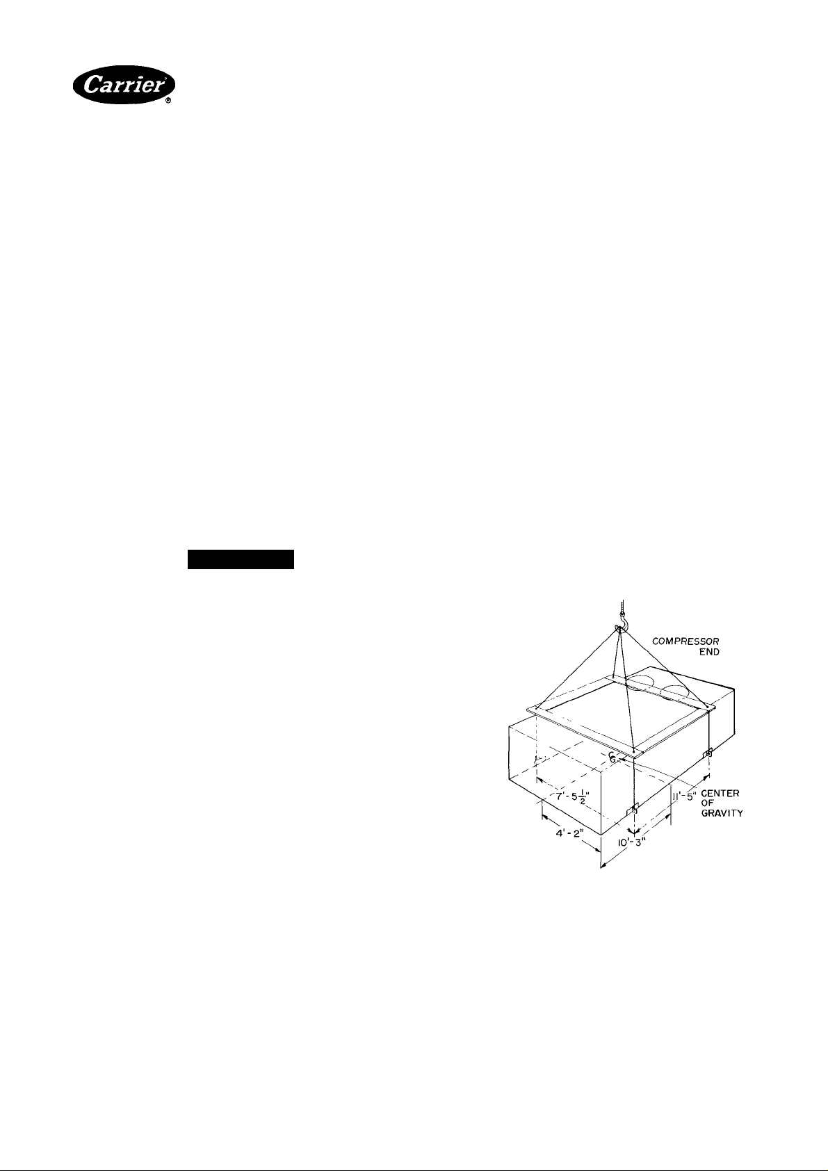
Rigging and Unit Placement — Inspect unit for
transportation damage. File claim with transportation
agency. Do not remove shipping skid until unit is ready
to be set in final location. Do not drop unit; keep upright.
Use spreader bars over unit to prevent sling or cable
damage. Rollers may be used to move unit across a roof.
Level by using unit frame as reference. See Fig. 1 for
additional information. Unit weight is shown in Table 1.
Units are designed to be hoisted only. However, units
with optional shipping skids may be moved with a fork
truck. Refer to Accessory Roof Curb Installation Instruc
tions for additional information as required.
Roof Curb — Assemble and install as described in
instructions shipped with this accessory. Accessory roof
curb and information required to field fabricate a roof
curb of 2-in.
insulation, cant strips, roofing and flashing as required.
For unit drains to function properly, curb must be level
or within tolerances shown in Fig. 3.
Roof Mount — Check building codes for weight dis
tribution requirements Unit weight is shown in Table 1.
Slab Mount — Provide a level concrete slab that
extends beyond unit cabinet at least 6 inches. Make a slab
8 in. thick with 4 in. above grade. Use gravel apron in
front of condenser air inlet to prevent grass and foliage
from obstructing airflow.
X 14-in. planks is shown in Fig. 2. Install
NOTES1 All unit panels must be In place when rigging.
2 Do not handle unit with fork trucks
3 Use 4 cables and four 2-by-4’s or 4-by-4's of dimensions
shown.
Fig. 1 — Rigging Details
Manufacturer reserves the right to discontinue, or change at any time, specifications or designs without notice and without incurring obiigations.
Book|l PC111 Catalog No 565-032 PrintedinUSA Form 50DF-9SI Pgl 4-86 Replaces: 50DF-7SI
Tab lib
For replacement items use Carrier Specified Parts
Page 2

NOTE' Certified dimension drawings available upon request
Fig. 2 — Roof Curb Dimensions
GASKET
RIGID INSULATION
(FIELD SUPPLIED)
CANT STRIP
(FIELD SUPPLIED)
3-|"{ENDS OF UNIT)
ROOFING MATERIAL
(FIELD SUPPLIED)
Field-Fabricated Ductwork — Secure all ducts to
building structure. Use flexible duct connectors between
unit and ducts as required. Insulate and weatherproof
all external ductwork, joints and all roof openings with
flashing and mastic in accordance with applicable codes.
Insulate ducts passing through unconditioned spaces
and cover with a vapor barrier.
Maintain one-in. minimum clearance between supply
air duct and any combustible material for at least 3 ft of
duct run from unit.
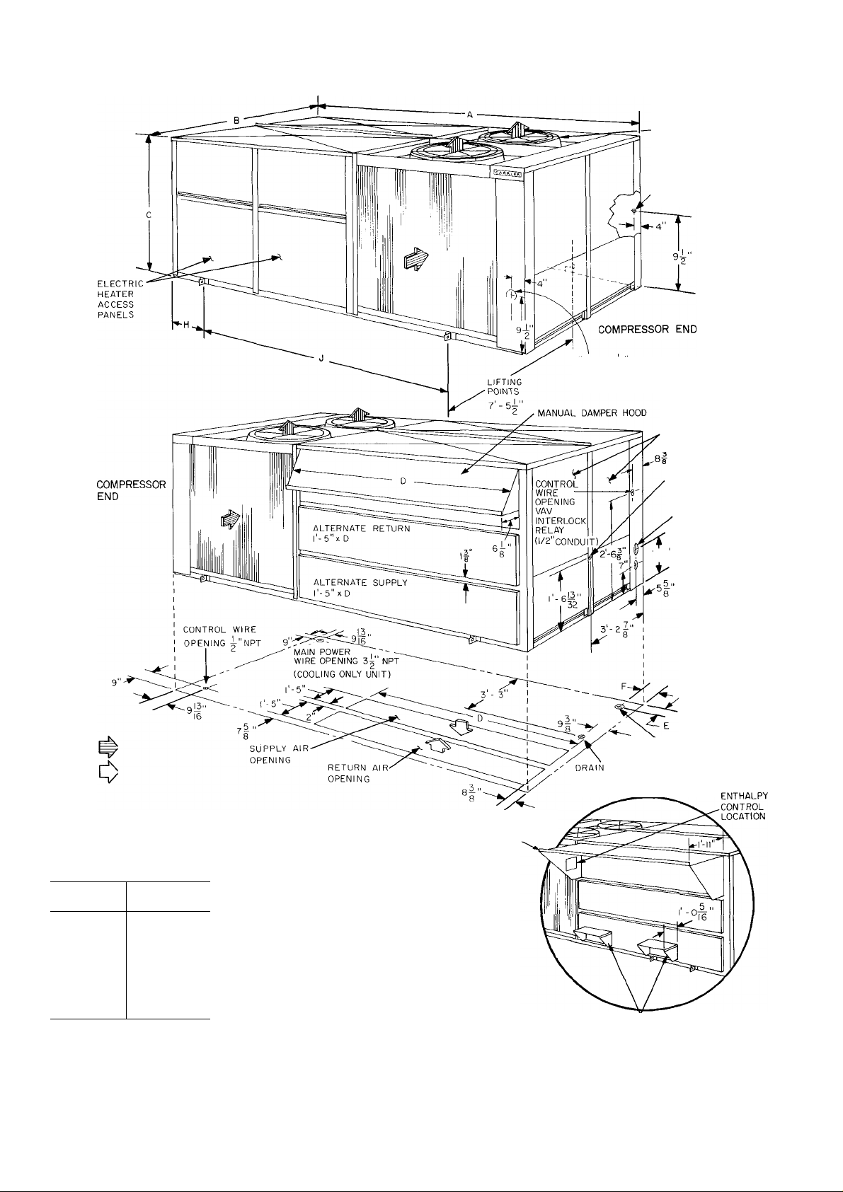
Unit is shipped set up for through-the-bottom duct
connections. Ductwork openings are shown in Fig. 4.
Field-fabricated concentric ductwork may be connected
to units as shown in Fig. 5.
Modifications are required to convert unit for throughthe-side duct connections.
Do not use side duct connections on units with optional
power exhaust packages or accessory barometric relief
dampers.
To convert unit for through-the-side duct connection,
refer to Fig. 6 and perform the following procedure.
(Units without optional economizer);
1. Remove return air filter access panel.
2. Remove side air opening panels. Save sheet metal
screws.
3. Remove return air filters.
4. Remove slant baffle that separates bottom flow supply
and return air paths. Save screws.
5. Reinstall baffle on top of horizontal plenum deck
so that deck opening is covered. Face insulation side
of baffle down. Drill holes in horizontal plenum deck
using baffle holes as location guide Use sheet metal
screws removed in step 4 to secure baffle to deck.
6. Install side air opening panels in bottom air openings.
Face insulation side up Drill holes in unit basepan,
using panel holes as location guide. Use sheet metal
screws removed in step 2 to secure panels to basepan.
7. Reinstall return air filters. Be sure all relocated com
ponents are secure.
8. Open manual outdoor air inlet hood as described
below.
Manual Damper Hood Adjustment — Loosen
hood adjustment bolts, pull hood open to desired setting.
Tighten bolts. See Fig. 4.
Page 3
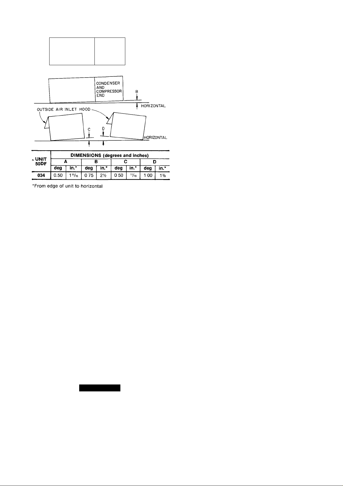
CONDENSER
AND
COMPRESSOR
END
Fig. 3 — Unit Leveling Tolerances
HORIZONTAL
10. Route the red and yellow wires through knockout
in side plate. Wrap end of blue wire with electrical
tape. Using wire connectors from envelope injunc
tion box, wire enthalpy control assembly as shown in
Fig. 8. Use strain reliefs from envelope on side plate
and junction box. Refer to Fig. 9 for Psychrometric
Chart for enthalpy control.
11. Install outdoor air screens.
12. Push retainer snugly against screens and tighten
screws.
Exhaust Air Hood Installation — The optional
power exhaust hood and damper assemblies and required
sheet metal screws are shipped in the compartment at
right of indoor air fan motor compartment. Using screws
provided, install a hood damper assembly over each
exhaust air opening as shown in Fig. 4. Power exhaust is
applied only to economizer units using bottom duct con
nections. Exhaust fan and motor assembly is factory
wired and adjusted. Refer to Service, Power Exhaust Air
Fan Adjustment if required.
Indoor Air Fans — The fan belt and pulleys are factory
installed and adjusted. If required, adjust as described
in Service, Indoor Air Fan Adjustment.
Economizer Section
ECONOMIZER HOOD INSTALLATION (Fig. 7) —
The economizer mechanism and all electrical connections
are factory installed and adjusted except as noted below.
Hood assembly, outdoor air inlet screens and required
hardware are shipped separately and must be field
installed.
Install economizer hood and enthalpy control as
follows:
1. Loosen unit top panel sheet metal screws above out
door air inlet opening.
2. Assemble hood top panel, side panels and support
channel.
3. Insert hood flange between unit top panel flange and
unit. Slots are provided in hood flange to clear sheet
metal screws. Tighten sheet metal screws. To insure
water tightness, apply RTV to edges as indicated
by shaded portions of Fig. 7.
4. Secure hood side panels to outdoor air opening
flanges, using screws provided.
5. Install hood support bracket(s) between U-channel
and support channel.
6. Install screen retainer on support channel, using
screws in the slots. Do not tighten.
7.
A CAUTION
Shut off main power to unit before installing
enthalpy control assembly.
8. Remove enthalpy control assembly from shipping
location on horizontal deck in return air filter
compartment.
9. Using 4 no. 10-1/2 screws from envelope in control
assembly junction box, mount enthalpy control
assembly to inside of economizer hood side panel
nearest condenser section (Fig. 4).
Condensate Drains — See Fig. 4 for drain locations.
Condensate drain is open to atmosphere and must be
trapped. Install a trapped drain line at connection to be
used. Trap must be at least 3 in. deep and made of flexible
material or be installed to prevent freeze-up.
Condensate drain pan under unit is fitted with a one-in.
FPT coupling. A gasket is shipped taped to this drain.
Install gasket in unit basepan opening or alternate open
ing on end of unit.
Field Power Supply — Unit is factory wired for
voltage shown on nameplate. The main power terminal
block is suitable for use with aluminum or copper wire.
See Fig. 10 and 11. Units have circuit breakers for
compressors, fan motors and control circuit. If required
by local codes, provide an additional disconnect switch.
If an external electrical source is used, unit must be
electrically grounded in accordanee with local codes, or
in the absence of local codes, with the National Electrical
Code, NFPA 70.
All field wiring must comply with National Electrical
Code and local requirements.
Install conduit connector in unit basepan or side panel
openings provided as shown in Fig. 4. Route power lines
through connector to terminal connections in control box
as shown in Fig. 10 and 11.
Affix crankcase heater sticker to unit disconnect
switch.
Voltage to compressor terminals during compressor
operation must be within voltage range indicated on unit
nameplate. Also, see Table 2. Phases must be balanced
within 2% Contact local power company for correction
of improper voltage or phase unbalance. Failure due to
operation of unit on improper line voltage or with exces
sive phase unbalance constitutes abuse and may cause
damage to unit electrical components.
Page 4
OUTDOOR AIR FANS
" (3)
ALTERNATE
CONTROL WIRE
OPENING
3 AND 4g- K 0
ALTERNATE FIELD-POWER WIRING
(COOLING ONLY UNIT )
INDOOR AIR FAN
AND FILTER
ACCESS PANELS
ALTERNATE
DRAIN 2|" KO d" MPT
L-2^" UNIT)
' CONDUIT
CONN INSIDE)
ALTERNATE
POWER WIRE
OPENING 3^“
(HEATING/COOLING
NPT
► OUTDOOR AIRFLOW
► INDOOR AIRFLOW
OPTIONAL
ECONOMIZER
AIR INTAKE HOOD
DSAM U"
^MPT CONN. INSIDE)
DIMENSIONS (ft-in :
UNIT
50DF
A
B
c
D
E 0-10yi6
F 0- 97a
G
H
J
Certified dimension drawings available on request
NOTES-
1. Allow 12 ft above unit, 8 ft on filter access panel end and 4 ft on remaining sides of unit for airflow and service clearance
2 For smaller clearances, contact manufacturer.
3 Refer to Roof Curb Dimensions for details of roof openings
034
17- 1
7- 3'/a
4-11
9- 0
4" NPT
2-10
11- 5
Fig. 4 Base Unit Dimensions
MAIN POWER WIRE
OPENING (G) (HEATING/
COOLING UNIT)
OPTIONAL
EXHAUST HOODS
(3)
V:
Page 5
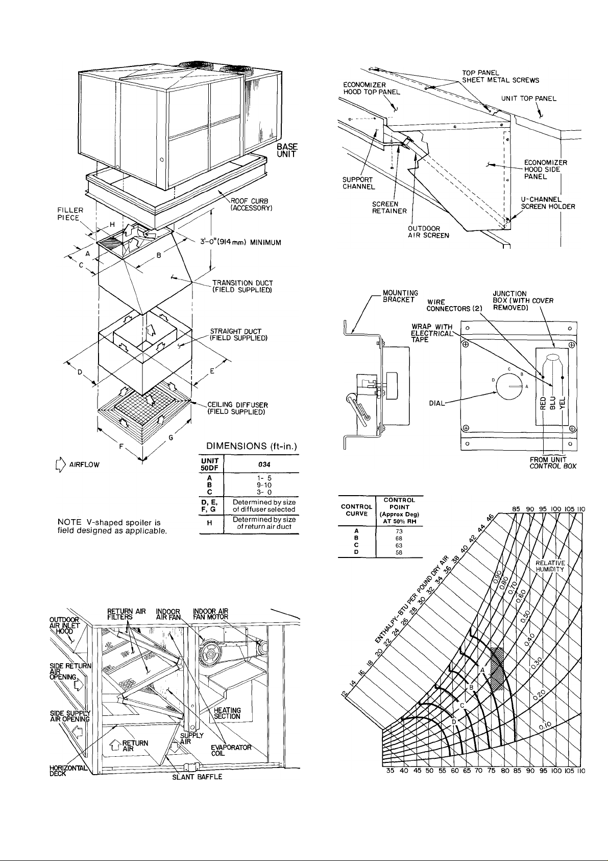
Fig. 5 — Concentric Duct Details
Fig. 7 — Economizer Outdoor Air Inlet
Hood Assembly
Fig. 8 — Enthalpy Control Assembly
Fig. 6 — Manual Damper Unit Indoor Air Section
DRY BULB TEMPERATURE (APPROXIMATE)-FAHRENHEIT
Fig. 9 — Psychrometric Chart for Enthalpy Control
Page 6

MAIN POWER TERMINAL BLOCK IN UNIT CONTROL
BOX OR HEATER COMPARTMENT
FIELD POWER
SUPPLY
THERMOSTAT SUBBASE
NOTE. Thermostat subbase required
TB4
MAIN CONTROL BOX
Fig. 10 — Field Wiring Connections — Without Energy Management Accessory
L3
L2
_i—
FIELD POWER
SUPPLY
TB9
LLI
NOTE Subbase not used
MAIN POWER TERMINAL
BLOCK IN UNIT CONTROL
LI
BOX OR HEATER
COMPARTMENT
II5V 60 Hz
230 V 50 Hz
(FIELD SUPPLIED)
I I
I "-1
LL2
Fig. 11 — Field Wiring Connections — With Energy Management Accessory
±
MAIN UNIT CONTROL BOX
2
1
- 1- *
THERMOSTAT
NIGHT SETBACK BOX (LOCATED IN BASE UNIT)
1 2 3
1
1
3
*
4 5
4 5 6
REMOTE BOX
____1
Ц—* * Ц—^ — —----------------------------------------------------
___
9
8
7
1
1
1
1
6 7 8 9 10 TB4
10
TB7
10
TB6
10
Page 7

Table 1 — Physical Data
UNIT50DF
OPERATING WEIGHT (lb)
Base Unit (includes heaters)
Base Unit with Economizer
COMPRESSOR
Quantity...Model
Oil (3GS orBIUots)
REFRIGERANT CHARGE (R-22)
System 1...System 2 (lb)
OUTDOOR AIR FANS
Number...Hp
Frame (NEMA)
Rom
INDOOR AIR FANS*
Single-Speed Motor Hp...Shaft Diameter (in.)
1750 Rpm
Single-Speed Motor Frame Size
Motor Pulley Pitch Diameter (in.) A...B
Fan Pulley Pitch Diameter (in.)
Fan Speed (rpm) A...B
Fan Shaft Diameter (in.)
Maximum Allowable Fan Speed (rpm)
ELECTRIC HEATERS
HIGH-PRESSURE SWITCH
Cutout (psig)
Cut-in (psig)
LOW-PRESSURE SWiTCH
Cutout (psig)
Cut-in (psig)
INDOOR AIR FILTERS (in.)
Standard; Quantity...Size (in.)
Throwaway
Optional; Bag Type, 12 in.
AIR INLET SCREENS
Economizer; Quantity...Size (in.)
034
4400
Serviceable, Reciprocating Hermetic
4600
2...06DA
10 (ea)
29.0...29.0
Direct Drive, Propeller
3 .1
56
1050
Fixed-Speed Centrifugal
15 .
254T
53 56
8.0
1159 1225
1 "/i6
1300
Refer to Electrical Data table
400 ±5
300 ± 5
27 ±4
67 ±7
2
9 20 X 25
12 16x25
5 12x24
5...24 X 24
5. 20 X 25
‘Pulley A is installed in unit, pulley B is shipped with unit
790
Page 8

Table 2 — Electrical Data
NOMINAL
VOLTS/PH/HZ
VOLTAGE
RANGE
Min
208-230/3/60 187 254 63 5
460/3/60
414 508
575/3/60 518 660 22
Compr — Compressor
FLA — Full Load Amps
Hp — Nominal Horsepower
kW — Kilowatts
LRA — Locked Rotor Amps
MCA — Minimum Circuit Amps
MOCP — Maximum Overcurrent Protection
RLA — Rated Load Amps
COMPR
Max RLA
27 5 120
NO. 1
LRA RLA LRA
266
63 5 266
27 5 120 3
96 22 96
COMPR
NO. 2
OUTDOOR
FAN MTR
FLA Hp
Oly
7 6
3
(ea)
3 3
(ea)
2 7
3
(ea)
*Fuse only
NOTES:
1 All outdoor fan motors are single-phase motors
2 All heaters are 3-phase assemblies
3 Circuit no. 2 is provided as indicated; total unit MCA is the sum of circuit
no 1 MCA and circuit no 2 MCA
4 Unbalanced 3-Phase Supply Voltage— Never operate a motor where a
phase imbalance in supply voltage is greater than 2% Use the following
formula to determine the % voltage unbalance
% Voltage Imbalance
max voltage deviation from average voltage
= 100 X ■
average voltage
INDOOR
FAN MTR
FLA
15 46 0
15
46 0 3 11
15
46 0
15
46 0
15
46 0
15
46 0
15
21 0
15
21 0
15
21 0
15
21 0
15
21 0
15
21.0 3
15
15
EXHAUST
FAN MTR
FLA kW FLA MCA
Hp
_ _ _ _
45-54 9
3 11
— —
3
45-54 9
75-91 5
11
75-91 5
_ _ _
3 4 8
3 4 8
— —
3
-
4.8
3 9
54 9
54 9
91 5
91.5
HEATERS
— —
125-138
125-138
208-230 212-212 250-250 156-173
208-230 223-223 250-250 156-173
214-230
223-230
_
— —
—
69
69
115 170
115
-
POWER SUPPLY*
Circuit 1 Circuit 2
MOCP
212 250
223 250
300-300
300-300
93 110
98 125
113
113
170 175
75
79
150
150
175
100
MCA
90
Example: Supply voltage is 460-3-60
AB = 452 volts
BC = 464 volts
AC = 455 volts
Average Voltage
452 + 464 + 455
3
1371
457
3
Determine maximum deviation from average voltage:
(AB) 457 - 452 = 5 volts
(BC) 464 - 457 = 7 volts
(AC) 457 - 455 = 2 volts
Maximum deviation is 7 volts
Determine % voltage imbalance:
% Voltage Imbalance = 100 x= 1 53%
This amount of phase imbalance is satisfactory as it is below the maxi
mum allowable 2%
MOCP
_
—
— —
175-200
175-200
— —
— —
__ __
— —
-
—
—
—
790
Í.
K
Page 9

f
Field Control Wiring
STANDARD UNIT (WITHOUT ENERGY MANAGE
MENT ACCESSORY) — Install a Carrier-approved
accessory electronic thermostat on a subbase (or a trans
mitter on subbase if remote sensor is used) per installation
instructions included with the accessory. Note that the
subbase must be used on constant volume units without
night setback. Locate thermostat, or remote sensor, if
used, in the conditioned space where it will sense average
temperature.
Route thermostat cable or equivalent single leads of
no 18 AWG colored wire from subbase terminals
through connector on unit to low-voltage connections in
main control box as shown on unit wiring diagram and
in Fig. 10.
UNITS WITH ENERGY MANAGEMENT ACCES
SORY — In addition to the standard control box, units
with energy management accessory are also equipped
with a remote box and a night setback box. The remote
box contains a 7-day time clock, a bypass switch that can
manually bypass the time clock for up to 5 hours, 6 indi
cator lights and 2 terminal blocks for field wiring con
nections. Mount this box remote from the unit in an
indoor or weathertight space. The night setback box
contains a terminal block for field wiring conneetions, a
morning warm-up thermostat and the setback/setup
module. The night setback box remains in the unit. Ship
ping locations of remote box and permanent location
of night setback box are shown in Fig. 12.
1. Remove remote box and mount in a restricted access
area (indoors or in a weathertight space).
2. Run separate 115-volt, 60-Hz (230-volt, 50-Hz) power
to the remote box per Fig. 11. Use no. 14 AWG wire
or larger and a proper field-supplied electrical
connector.
3. Install a Carrier-approved accessory electronic
thermostat or transmitter if remote sensor is used
(subbase not required) according to the installation
instructions included with the accessory. Note that
the subbase is not used on units with the energy
management accessory. Locate the thermostat or
rernote sensor, if used, in the conditioned space where
it will sense average temperature.
Route thermostat cable or equivalent single leads of
no. 18 AWG colored wire from thermostat or trans
mitter terminals through connector on unit to lowvoltage (TB4) connections in main control box as
shown on unit label wiring diagram and in Fig. 11.
4. Run 24-volt wires between the remote box and night
setback box per Fig. 11. Use no 18 AWG wire for
lengths up to 1000 feet. Local codes may dictate use
of conduit for low voltage. Knockouts are provided in
the night setback box and in the fan deck separating
heating section from section containing the night
setback box (Fig. 12). A watertight connector is in
stalled in side of unit. Two rubber grommets are taped
inside the night setback box. Use grommets in knock
outs in fan deck and night setback box.
REMOTE CONTROL
Fig. 12 — Shipping Locations — Remote Box
Return Air Filters — Check that return air filters are
of the correct type and size and installed in unit filter
racks. Filter data is shown in Table 1 Do not operate
unit without return air filters
Outdoor Air Inlet Screens — Outdoor air inlet
screens must be in place before operating unit.
Compressor(s) — Loosen compressor holddown
bolts until sidewise movement of the washer under each
holddown bolt head occurs Do not loosen completely
as bolts are self-locking and will maintain their
adjustment.
Open the compressor discharge and suction service
valves. Replace and tighten valve caps to prevent leaks.
Liquid Line Service Valve — Open the liquid line
service valve Replace and tighten valve cap to prevent
leaks.
Low Ambient Compressor Lockout(Fig. 13) —
All units are equipped with an adjustable low ambient
lockout thermostat to lock off the compressor(s) at low
outdoor air ambients. Thermostat is located in the main
control box. Setting will depend on specific installation
but should be approximately 55 F on constant volume
units.
Convenience Outlet — All units are equipped with
a 115-volt convenience outlet for handling small power
load or service light. See Fig. 13.
Page 10

CIRCUIT BREAKERS
MOVE SWITCH TO
POSITION FOR
DESIRED HEATING SETBACK
CONVENIENCE OUTLET LOW AMBIENT LOCKOUT
Fig. 13 — Control Box
THERMOSTAT
LOOIC PANEL
(A) HEATING SETBACK
Fig. 14
Accessory Setback/Setup Module (Partial)
Constant Volume Units
COOLING (WITH OR WITHOUT ENERGY
MANAGEMENT ACCESSORY)
1. Open compressor service valves. Make sure the crank
case heater has been on for at least 24 hours to remove
liquid refrigerant from compressor crankcase. Check
compressor oil level. Oil sight glass should be half full.
2. Be sure that the liquid line service valve is open and
that high- and low-side refrigerant service ports are
closed as applicable.
3. On units equipped with the energy management acces
sory, move the COOL SETUP SELECT jumper wire
to the desired setting (5°, 8°, or 12°). If cooling is not
desired during the unoccupied periods, move jumper
wire from COOL SETUP to COOL LOCKOUT. See
Fig 14.
4. Turn on power to unit. On standard units, set the
subbase selector switch to COOL. On units with the
energy management accessory, set the 7-day time clock
(B)COOLING SETUP OR LOCKOUT
START-UP
as required. Refer to 7-Day Time Clock Adjustment.
Check that compressor low ambient lockout contacts
and morning warm-up contacts (on units with energy
management accessory) are closed.
5. Remove cover from thermostat (or from transmitter
if a remote sensor is used); note the red diagnostic
light-emitting diodes (LED’s). See Fig. 15.
6. To call for cooling, move the thermostat or transmitter
cooling set point (blue lever) below room temperature.
Cooling LED on the right-hand side of thermostat or
transmitter should begin to glow. Check the cooling
effect at supply duct outlets If the mechanical cooling
does not come on, see Service, Electronic Component
Checkout.
7. Move the thermostat or transmitter cooling set point
above room temperature. The cooling equipment
should cycle off and the cooling LED intensity should
decrease to a faint glow or go off completely. The
economizer should move to minimum position.
10
Page 11

r
HEATING
LEVER(RED)
COOLING
LEVER (BLUE)
THERMOSTAT
CAPTIVE TERMINAL MOUNTING SCREWS
THERMOSTAT/TRANSMITTER
Fig. 15 — Electronic Thermostat/Transmitter (without subbase)
(Which must be ordered as an accessory)
To Shut Off Unit— For standard units, set the subbase
selector switch to OFF or set the cooling temperature
selector lever above room temperature. For units with
energy management accessory, set the cooling tem
perature selector switch above room temperature.
Do not shut off unit circuit breakers except when unit
is serviced. Crankcase heater is energized onlv when unit
power is on.
HEATING (Electric Heat Units)
1. Turn on unit power; set circuit breakers at ON.
2. On units with energy management accessory, position
the HEAT SETBACK SELECT switch in the setback/setup module to the desired position (5°, 10°,
15°). See Fig 14
3. Move the thermostat or transmitter heating set point
(red lever) above room temperature The heating LED
on the left-hand side of thermostat or transmitter
should begin to glow. Electric heat should cycle on.
Check supply duct outlets for heat. If heating equip
ment does not cycle on, see Service, Electronic Com
ponent Checkout.
4. Move the heating set point below room temperature.
The heating equipment should cycle off and the heating
LED intensity should decrease to a faint glow or go
off completely.
5. Return the heating and cooling set points to desired
settings and lock in place. On standard units, return
subbase switch to desired position. On units with
energy management accessory, an adjustable morning
warm-up thermostat is used to hold dampers closed
until return air reaches the setting on the thermostat
located in the night setback box.
To Shut Off Unit — Standard units, set the subbase
selector switch to OFF or set the heating temperature
selector lever below room temperature. For units with
energy management accessory, set the heating tempera
ture selector switch below room temperature
AUTOMATIC CHANGEOVER — Standard units
automatically switch from heating to cooling mode when
the subbase selector switch is set at AUTO, and the
temperature of the conditioned space rises to the cooling
selector lever setting When the temperature of con
ditioned space falls to heating selector lever setting, the
unit automatically changes from cooling mode to heat
ing mode.
The thermostat and unit are so connected that cooling
and heating systems do not operate simultaneously.
On units with energy management accessory, with
dual set point thermostat or transmitter, changeover is
also automatic. There is a minimum 3 F deadband
between the heating and cooling set points
ECONOMIZER OPERATION — If unit is equipped
with modulating outdoor air control (economizer), set
enthalpy control (Fig. 4 and 8) at “A.” Unit capability
to integrate economizer with mechanical cooling allows
for a higher changeover point than conventional econo
mizer systems. Because of this, outside air is desired
whenever its enthalpy (total heat content) is below return
air enthalpy. Typical return air conditions, shaded
portion of Fig. 9, indicate that setting “A” should be
used for maximum operating economy.
OPERATING SEQUENCE WITH ECONOMIZER
(without energy management accessory) using thermo
stat with subbase.
Cooling — System switch set at AUTO, or COOL, fan
switch at ON or AUTO, (indoor air fan runs inter
mittently). Thermostat set at desired setting.
When thermostat calls for cooling and outdoor air
enthalpy is below setting of enthalpy controller, the
economizer modulates open. (If outdoor air enthalpy is
II
Page 12

above enthalpy set point, the outdoor air dampers remain
at minimum position.) Economizer acts as the first stage
of cooling, providing “free cooling” with outside air. If
outside air alone cannot satisfy the cooling requirements
of conditioned space, economizer cooling is integrated
with mechanical cooling.
Compressor(s), working simultaneously with econo
mizer, will come on in stages to meet the cooling load.
As the conditioned space temperature approaches the
thermostat’s cooling set point, stages cycle off, last stage
first. After all stages of mechanical cooling are off, econo
mizer modulates to minimum position.
During the cooling cycle, a discharge air sensor senses
discharge air temperature. If discharge air temperature
drops below 62 F, economizer starts to modulate toward
minimum position. At 50 F discharge temperature, the
economizer will be at minimum position.
Heating — System switch set at HEAT or AUTO., fan
switch at ON or AUTO., thermostatset at desired setting.
When thermostat calls for heating, one or 2 stages of heat
energize to satisfy heating demand.
As space temperature approaches the heating tem
perature set point, heating stages cycle off.
During heating, economizer is limited to the minimum
position to provide outdoor air for ventilation
requirements.
OPERATING SEQUENCE WITH ECONOMIZER
AND ENERGY MANAGEMENT ACCESSORY
(using electronic thermostat or transmitter).
Clock in remote control box switches controls to
OCCUPIED mode. Indoor air fan runs continually while
in OCCUPIED mode
If return air temperature is below the adjustable setting
of morning warm-up thermostat, outdoor air dampers
remain closed.
When return air temperature goes above setting of
morning warm-up thermostat, economizer goes to adjust
able minimum position.
When thermostat calls for cooling and outdoor air
enthalpy is below setting of enthalpy controller, econo
mizer modulates open. (If outdoor air enthalpy is above
enthalpy set point, economizer remains at minimum
position.) The economizer acts as the first stage of cool
ing, providing “free cooling” with outside air. If outside
air alone cannot satisfy cooling requirements of the
conditioned space, economizer cooling is integrated with
mechanical cooling.
Compressor(s), working simultaneously with econo
mizer, will come on in stages to meet the cooling load.
As the conditioned space temperature approaches the
thermostat’s cooling set point, stages cycle off, last stage
first. After all stages of mechanical cooling are off, econo
mizer modulates to minimum position.
During the cooling cycle, a discharge air sensor senses
discharge air temperature. If discharge air temperature
drops below 62 F, the economizer modulates toward
minimum position. At 50 F discharge temperature, the
economizer will be at minimum position.
At the end of the DAY (OCCUPIED) mode on the
clock, unit controls enter the NIGHT (UNOCCUPIED)
mode Economizer closes. Indoor air fan runs only on a
call for heating or cooling. Temperature controls go into
HEATING SETBACK, COOLING SETUP or COOL
ING SHUTDOWN mode.
HEATING SETBACK is field selectable at the unit
for 5°, 10°, or 15° below set point on room thermostat.
COOLING SETUP is field selectable at the unit for
5°, 8°, or 12° above set point on room thermostat.
During the UNOCCUPIED mode, unit continues to
use economizer cooling first and then integrates econo
mizer cooling with mechanical cooling to meet cooling
requirements.
A 5-hour bypass timer is located in the remote control
box to provide air conditioning during normally un
occupied hours
POWER EXHAUST OPERATION — Units have an
auxiliary switch located on the damper motor. This
switch is factory set to prevent the power exhaust fans
from operating when the economizer damper is less than
30% open.
If other than factory setting is desired, adjust as follows:
NOTE. Adjustment does not require running the motor
1. Motor must be in the fully closed position.
2. Referring to Fig. 16, take off “C” clip and drive
bracket. Remove screws at 4 corners of housing. Pull
off return spring housing.
STARTING POSITION
NOTE POSITION
OF RED DOT
CENTERLINE
Each adjustment mark repre
sents 10 degrees of motor ro
tation Use marks and center
of cam roller as adjustment
guide
Red dot will be to right of centerline if switch is properly adjusted
Fig. 17 — Adjusting Switch Make and Break Points
ADJUST CAMS
OPERATIONAL
Loosen operational cam ad
justment screw Rotate both
cams clockwise the number
of degrees motor must travel
before switch makes Tighten
screw.
12
Page 13

3. Remove spring on motor shaft.
4. Adjust switch as shown in Fig. 17.
5. After adjustment, replace spring on motor shaft and
reassemble return spring housing.
CAPACITY CONTROL, HEATING — Stages 1 and 2
of heaters are controlled by heating relays H R1 and H R2,
respectively. Using a suitable ammeter, check heater
current draw for heating assemblies or elements. When
checking second-stage heater operation, be sure heating
thermostat is set high enough to activate second-stage
heaters Also, check operation of outdoor air thermo
stats if additional staging is provided
TIME GUARD® CIRCUIT — Timer sequence for a
particular unit depends on unit and compressor arrange
ment. The Time Guard device provides a delay in com
pressor start-up after thermostat closes. On normal unit
start-up, outdoor air fans energize 15 seconds before the
compressor. If compressor/shutdown is due to satisfied
thermostat or automatic resetting of a safety device, the
compressor automatically restarts after a 5-minute
interval. If compressor shutdown is due to tripped over
loads, the circuit breakers must be manually reset before
compressor will start.
Timer (Time Guard) for second compressor has a 6minute interval to prevent compressors from starting
simultaneously.
Refer to unit label diagram for specific timer sequence.
CRANKCASE HEATER — Unit main power supply
must remain on to provide crankcase heater operation.
Crankcase heater in each compressor keeps oil free of
refrigerant while compressor is off.
HEAD PRESSURE CONTROL — Each unit has a fan
cycling thermostat to shut off outdoor fan motors at 55 F.
This permits unit to operate with correct condensing
temperatures down to 35 F outdoor air temperature.
SERVICE
Electronic Component Checkout
A CAUTION
Control circuit must be checked with system power
on. Disconnect power before checking wiring and use
care to avoid electrical shock and prevent equipment
damage.
____________________
The checkout procedures in this section will determine
whether-
1. The logic panel is controlling the heating and cooling
equipment properly.
2. System components are correctly wired to the logic
panel.
Prior to checking out control circuit, establish setting
on the low ambient lockout thermostat. Compressors
will not start below this setting (cooling mode only).
Recommended setting is approximately 50-55 F.
NOTE: To complete the electronic component checkout,
a volt-ohmmeter (Simpson 260 is recommended) is
required.
LOGIC PANEL (Fig. 18)
I. Check that 24 vac is supplied to logic panel Connect
meter to terminals TR.
2 Check thermostat supply voltage at STAT terminals
1 and 2. Reading should be 20 vdc.
Fig. 18 — Logic Panel (Standard Unit)
3 Remove thermostat supply wires from ST AT ter
minals 1 through 5 on logic panel.
4. Set meter to volts ac scale equal to relay switching
voltage (50-volt scale for 24 vac).
5. To simulate a call for cooling, jumper between STAT
terminals 2 and 4. Normally open logic panel contacts
(COOL 1 and 2) should close and cooling equipment
should cycle on.
6. Connect meter leads to the normally open cooling
contacts 1 and 2 on logic panel. Meter should read zero
if contacts have closed and contacts are made.
If meter is reading zero and cooling equipment has
not cycled on, logic panel is not at fault.
7. To simulate a call for heating, jumper between ST AT
terminals 2 and 5. Normally open logic panel contacts
(HEAT 1 and 2) should close and heating equipment
should cycle on.
8. Connect meter leads to the normally open heating
contacts on logic panel. Meter should read zero if
contacts have closed.
If meter is reading zero and heating equipment has
not cycled on, logic panel is not at fault.
9. Replace thermostat wiring to terminals 1 through 5.
DISCHARGE SENSOR
1 Set resistance on meter to R x 100.
2. Disconnect lead from SENSOR terminal T1 on logic
panel.
13
Page 14

3. Connect one meter lead to logic panel terminal T and
the other meter lead to the loose lead wire from the
sensor.
4. Meter readings depend on temperature. Discharge
sensor readings should be between 1500 and 4500
ohms. See Fig. 19.
THERMOS!AT/TRANSMITTER (Fig. 15)
1. Set meter to 20 vdc scale.
2. Check for power to thermostat. Connect negative (-)
lead to terminal 1 and positive (+) lead to terminal 2.
Meter should read 20 vdc.
3. Connect the negative (-) lead to terminal 1 and the
positive (+) lead to terminal 4.
4. Slowly move the cooling lever below room tempera
ture to simulate a call for cooling. Meter reading
should gradually increase to about 16 vdc. (See
Fig. 20.)
5. Move the cooling lever above room temperature.
Meter reading should drop to less than 2 vdc.
6. Remove the (+) meter lead from terminal 4 and
connect it to terminal 5.
7. Slowly move the heating lever above room tempera
ture to simulate a call for heating. Meter reading
should gradually increase to about 16 vdc. (See
Fig. 20.)
8. Move the heating lever below room temperature. The
meter reading should drop to less than 2 vdc.
5000
4800
4600
4400
4200
4000
3800
3600
3400
3200
3000
2800
2600
2400
2200
2000
1800
1600
1400
1200
1000
800
600
400
200
\ 3000ÍIA1
60 65 70 75 80 85 90 95 100
(16) (18) (21) (24) (27) (29) (32) (35) (38)
TEMPERATURE DEGREES F (DEGREES C)
77F( 250
L
Fig. 19 — Resistance Range of the
Discharge Sensor
1
ECONOMIZER (Motor Operation) — Check to see 115 v
is at the economizer motor. Remove wire from the W
terminal on damper motor. Dampers should go fully
open.
Short between R-W on motor terminals. Dampers
should go fully closed.
Logic Panel Economizer Signal
Disconnect terminal W on logic panel.
Connect meter (2.5 vdc scale) with negative (-) lead to
R and the positive (+) lead to W.
Set thermostat for a call for cooling. Meter reading
3.
should rise to 1.5 vdc. If thermostat was already calling
for cooling, reading will be 1.5 v when meter is
connected.
4. Turn thermostat up so that no cooling is called for.
Voltage should fall from 1.5 vdc to 0.
Conduct the above test with air temperature at the
discharge sensor (located at unit air discharge) above
62 F. If air is below 50 F, there will be no voltage
signal. If air is between 50 and 62 F, voltage will be
in the same proportions.
A CAUTION
When servicing unit, shut off all electrical power
to unit to avoid shock hazard or injury from rotat
ing parts.
Cleaning — Inspect unit interior at the beginning of
each heating and cooling season and during each season
as operating conditions require. Remove unit top panel(s)
and/or side panels as required to expose unit interior.
EVAPORATOR COILS — Clean with a stiff brush,
vacuum cleaner or compressed air.
CONDENSER COILS — Clean with a stiff brush or
vacuum cleaner. When cleaning with compressed air or
low-pressure water or steam, guard against damaging
VOLTAGES NECESSARY TO ACTIVATE LOGIC PANEL
HEAT STAGE
1
2
Differential 63 ± .07 volts
VOLT DC COOL STAGE VOLT DC
4 63
5 88 2 5 88
1
Tolerance' ± 25 volts
5 00
Fig. 20 — Thermostat/Transmitter Output
Voltage Ramps
compressor wiring and nearby controls. Condenser fan
motor(s) is drip-proof but not waterproof.
CONDENSER SECTION DRAIN — Check that area
under coil is clear and drains freely.
CONDENSATE DRAIN — Check and clean annually
at start of cooling season. In winter, keep drain and trap
dry or protect against freeze-up.
FILTERS — Replace filters at start of each heating and
cooling season or as often as necessary during each
season, depending on operating conditions. Refer to
14
Page 15

Table 3 — Indoor Air Fan Data
UNIT
CFM 0.20
50DF
034
Boldface indicates aiternate or field-supplied fan motor or drive is required.
Bhp — Brake horsepower
Rpm — Revolutions per minute
NOTES:
1 Values in italics indicate that motor larger than optional fan motor is required
2 Fan performance has deductions for unit casing losses, wet coil and clean standard filters
3 Fan motor bhp is based on minimum voltages and 80 F air across motor
Rpm Bhp
9,000 690
720 3 29
9,500
10,000 751
782 4 28 842
10,500
814
11,000
845
11,500
12,000 877
12,500 909
941
13,000
973
13,500
1006
14,000
1038
14,500
1071
15,000
2 86
3 76
4 80 871
5 50
6 10 931
6 80 962 7 70 1010
7 60 992 8 50
8 50 1023 9 40
9 40 1054 10 40
10 30 1085 11.40
11 30 1116 12.40
0.40
Rpm
Bhp Rpm
755
3 40
784
3 88 839 4 42 891 4 95 940
813
4 40
4 96
5 60 923
901 6 20 952
7 00
0.60 0.80
Bhp Rpm
812
3 91 865
867 4 97
895 5 57
6 20 971
6 90
981
7 70
8 50
1039
9 40 1 1083
1069 10 30
1099 11.30
1129 12.30
1159 13.50
917 5 53
943 6 16
999 7 60 1042 8 20
1027
1055
1112
1141
1170
1200
EXTERNAL STATIC PRESSURE (in. wg)
1.00
Bhp Rpm
4 42 916
6 80 1016 7 50
8 40 1069 9 00
9 20 1097 9.90
10.10 1125 10.90
11.10 1153 11.90
12.10
13.20
14.40
Bhp
4 94
5 49
964 6 09
990 6 75
1181 12.90
1209
14.10
1238 15.30
Table 1 for type and size of filter used. Filter access panels
are shown in Fig. 4. Return air filter tracks will accept 2
layers of one-in. thick filters if 2-in. filters are not avail
able. Do not install bag filters in standard filter tracks.
Do not install standard filters or 2-in. high-efficiency
filters in bag filter tracks.
OUTDOOR AIR INLET SCREEN(S) — Clean screens
with steam or hot water and mild detergent. Do not use
throwaway filter in place of these screens. Loosen
fastening-bracket screws and slide out screens.
Lubrication
COMPRESSORS — Each compressor is charged with
correct amount of oil at the factory. Oil level should be
between bottom and mid-level of sight glass when com
pressor is warm. Refer to 06D or 06E Compressor Serv
ice Manual if additional information regarding com
pressor lubrication system is required.
FAN SHAFT BEARINGS — Charge each grease fitting
with a suitable bearing grease at least once a year. Do
not overlubricate.
FAN MOTOR BEARINGS — No relubrication of out
door air fan motors is necessary for first 2 to 5 years of
use, depending on operating conditions Annually there
after, open, clean and repack each bearing with a suitable
bearing grease
Indoor air fan motor bearings should be cleaned and
repacked with a suitable bearing grease annually after
initial unit installation.
1.20
Rpm Bhp Rpm
960 5 42
985 6 03
1010 6 67
1034 7 35
1059
8 10
1085 8.90
1110 9.70
1136 10.60
1163 11.60 1201
1191
12.60
1218 13.70 1254
1246 14.90
1275
16.10
1.40 1.60 1.80 2.00
Bhp Rpm
1006 5 94 1052
1026 6 54
1051
1076
1100 8.70
1125
1150
1176
1227
1282 15.70
7 22
7 96 1114
9.50
10.40
11.30
12.30
13.40
14.50
1071
1091 7.77
1139
1164
1188 11.10
1213
1238 13.10 12^
1264 14.10
1290 15.30
Bhp Rpm
6 48
7 10
8.51
9.30
10.20
12.00
Bhp Rpm Bhp
1094 7.02 1133
1114 7.67
1133 8.36 1174 8.97
1152 9.10 1193 9.73 1232 10.37
1174
9.90
1200 10.80
1225 11.80 1258 12.40
1249 12.80 1284 13.50
13.80
14.90
1298
7.57
8.24
1153
1212 10.50
1233 11.40
Rpm Bhp
1173 8.18
1190
1211 9.56
1250
1270 12.10
1291 13.10
After reinstalling pulley and belt, check pulley align
ment and belt tension as described below.
PULLEY ALIGNMENT — Loosen fan shaft pulley
bushing and slide pulley along shaft. Make angular
adjustment by loosening motor mounting plate and repo
sitioning it as required.
BELT TENSION — Adjust belt tension by moving
motor back until only a slight bow appears in the belts on
the slack side of the drive while running under full load.
Secure motor. Recheck belt tension after 24 hours of
operation, adjust as necessary.
Table 4 — Indoor Air Fan Pulley Data
UNIT
50DF
'Remove one belt
NOTE: Values shown indicate standard or optional pulley combinations
available as shown in Physical Data table All other combinations are field
supplied and shown in boldface type
FAN
RPM
1073 2-3V-6.5
1093
1141
1159 4-3V-5.3
1225 4-3V-5.6
1300
MOTOR
PULLEY
No. Grooves-Type-ln.
925 2-3V-5.6 2-3V-10.6
991 2-3V-6.0 2-3V-10.6
3-3V-5.0
4-3V-4.5
3-3V-6.0
FAN
PULLEY
2-3V-10.6
3-3V- 8.0
4-3V- 6.9
4-3V- 8.0
4-3V- 8.0
3-3V- 8.0
SINGLE-SPEED
BELT
NO.-SIZE
2-3V-750
2-3V-750
2-3V-750
3-3V-710
4-3V-670
4-3V-710
4-3V-710
3-3V-710
2.20
8.81
11.20
Indoor Air Fan Adjustment — Fixed fan speeds
are set as shown in Table 1. If other than available fan
speeds are required, select field-supplied motor or
pulleys, using data from Tables 3 and 4.
PULLEY REMOVAL — Pulleys are of the fixed type
and have taper-lock bushings. To remove, shut off unit
power. Loosen fan motor mounting plate and remove
belt. Relocate taper-lock bushing bolts in removal holes
to loosen bushing. Remove pulley from shaft.
Power Exhaust Air Fan Adjustment (if fitted) —
Adjust belt tension so that 1/8-in. deflection at 5- to
8-pounds pressure between pulley centers can be
obtained. To change tension, loosen motor mounting
bolts, reposition motor and tighten mounting bolts.
Tighten locknut and bolt under motor mounting plate
to secure in fixed position.
15
790
Page 16

Outdoor (Condenser) Air Fan Adjustment
(Fig. 21) — Shut off unit power supply Remove fan
guard and loosen fan hub setscrews Adjust fan height
using a straight edge laid across venturi. Tighten set
screws and replace rubber hubcap to prevent hub from
rusting to motor shaft. Fill hub recess with Permagum
if hub has no rubber hubcap.
Fig. 21 — Outdoor Air Fan Adjustment
Damper Vent Position Setting
1. On constant volume units, adjust thermostat or trans
mitter so there is no call for cooling. On variable
volume units, adjust set point knob on microprocessor
so there is no call for cooling. The economizer
dampers go to minimum position
2 Remove cap from vent adjustment screw on top of
damper motor terminal box cover
3. Turn adjustment screw slowly until dampers assume
desired vent position. Do not manually operate
clamper motor. Damage to motor will result.
POWER FAILURE — Dampers have a spring return.
In the event of a loss of power, dampers close until power
is restored Do not manually operate damper motor.
Damage to motor will result.
Refrigerant Charge — Amount of refrigerant charge
is shown on unit nameplate and in Table 1. When charg
ing refrigerant system, refer to Carrier Standard Service
Techniques Manual, Chapter 1, Refrigerants. When
adding a complete charge, evacuate the system using
standard evacuating procedures and weigh in specified
amount of refrigerant. A charging chart (Fig. 22) is pro
vided on unit control box door above compressor and
may be used (use of sight glass not required).
When using refrigerant liquid line sight glass to charge
system:
1. Install a jumper on the low-pressure switch if required.
2. Operate unit with restricted condenser airflow to
achieve an operating discharge pressure of about
375 psig.
3. Slowly add refrigerant until sight glass clears.
4. Remove jumper from low-pressure switch and remove
condenser air restriction.
Fig. 22 — Charging Chart; 50DF034, System 1 and System 2
Manufacturer reserves the right to discontinue, or change at any time, specifications or designs without notice and without incurring obligations.
Book|l PC111 Catalog No 565-032 PrintedinUSA Form50DF-9SI Pg 16 790 4-86 Replaces: 50DF-7SI
Tab 1b
For replacement items use Carrier Specified Parts
 Loading...