

Page 1
Number One
AirConditbning
Maker
Instiillation, Start-U|5
I Division of
" Carrier Corporatio
Carrier Parkway • Syracuse NY 13221
and Service Instructions
Single-Package Cooling Units
SAFETY CONSIDERATIONS
Installation and servicing of air conditioning
equipment can be hazardous due to system pressure
and electrical components. Only trained and quali
fied service personnel should install, repair or
service air conditioning equipment.
Untrained personnel can perform basic mainte
nance functions of cleaning coils and filters and
replacing filters. All other operations should be per
formed by trained service personnel. When working
on air conditioning equipment, observe precautions
in the literature, tags and labels attached to the unit
and other safety precautions that may apply.
Follow all safety codes. Wear safety glasses and
work gloves. Use quenching cloth for unbrazing
operations. Have fire extinguisher available for all
brazing operations.
INSTALLATION
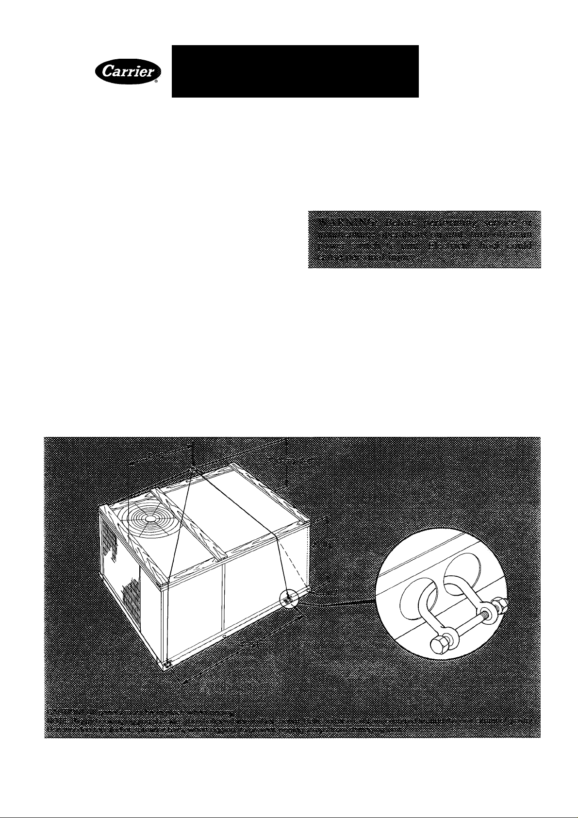
Unit Rigging and Placement — Inspect for trans
portation damage. File any claim with transporta
tion agency. Spreader bars are not required if top
crating is left on unit. Keep unit upright. Do not
drop unit (see Fig. 1). Rollers may be used to move
unit across a roof. Level by using frame as a refer
ence. Leveling tolerance is ± 1 / 16-in. per linear foot
in any direction. This is necessary for condensate
drain to function properly. Table 1 shows unit
weight. See Fig. 1 for rigging details.
Fig. 1 — Rigging Details
© Carrier Corporation 1983 Form 50CD-23SI
Page 2
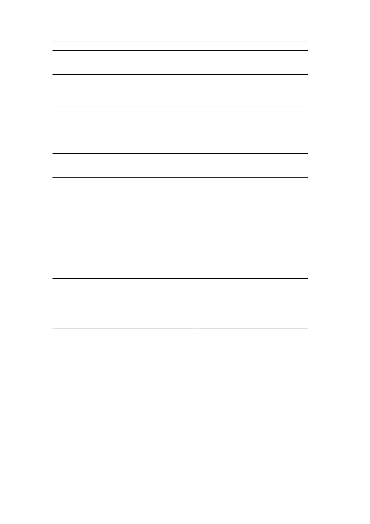
Table 1 — Physical Data
UNIT SIZE
OPERATING WEIGHT (lb)
Unit
With Economizer* 790
Roof Curb* — 14 in. 120
COMPRESSOR
No. ...Type
Oil (oz)
REFRIGERANT (Capillary Control)
Charge (lb)
CONDENSER COIL Copper Tubes, Aluminum Fins
Rows
Fins/in.
Total Face Area (sq ft)
CONDENSER AIR FAN
Nominal Cfm
No. ...Diameter (in.)
Motor Hp (1075 Rpm)
EVAPORATOR COIL
Rows
Fins/in. 13 9
Total Face Area (sq ft)
EVAPORATOR AIR FAN
Quantity...Size (in )
Nominal Cfm
Minimum and Maximum Cfm (Standard Motor) 2250 - 3650
(Optional Motor) 2250 - 3750
Rpm Range
Maximum Allowable Rpm
Motor Pulley Pitch Diameter (in.)
Fan Pulley Pitch Diameter (in )
Belt No. ...Type
Speed Change per Full Turn of
Moveable Pulley Flange (Rpm)
Moveable Pulley Maximum Full Turns
from Closed Position
Factory Setting — Full Turns Open 3
Factory Speed Setting (Rpm) 760
Motor Hp (Service Factor) Standard 1 Hp (1 4)
Optional 1 5 Hp (1 3)
HIGH-PRESSURE SWITCH
Cutout (psig)
Reset (psig)
LOW-PRESSURE SWITCH (Liquid Line)
Cutout (psig)
Reset (psig)
OUTDOOR AIR INLET SCREENS*
Economizer, No . Size (in ) 2 19 X 31 X 1/2 — None on 50CH008
RETURN AIR FILTERS* (Type) Disposable — None on 50CH008
No. ...Size (in.)
»50CD008 only
50CD/CH008
730
1 — BRE2 Copeland
124
R-22
105
2
13 9
15 6
4100
1 22
1/2 Hp
Copper Tubes, Aluminum Fins
3
82
1 12x9
3000
652 - 924
924
2 4-3 4
12 7
1 A51
54
426 ± 7
320 ± 20
27 ± 4
67 ± 7
2 16 X 20 X 1
2 20 X 20 X 1
Accessory Roof Curb (50CD008) — See Fig. 2.
Assemble and install in aeeordance with instruetions
shipped with curb. Install insulation, cant strips,
roofing and flashing as required. Ductwork must
be attached to curb.
Unit gasketing to roof curb is critical for water
integrity. Make sure that gasketing material shipped
with the roof curb has been properly installed as
indicated in Fig. 2.
Roof Mount — Check building codes for weight
distribution requirements. Table 1 shows unit
weight.
Slab Mount (50CH008) — Provide a level con
crete slab the same width as unit that extends to ends
of base rails only. The slab should be 8 in. thick with
4 in. above grade. Install a gravel apron in front of
©
outdoor air inlet to prevent grass and foliage from
obstructing airflow. Allow a minimum of 6 in. under
outdoor coil for condensate drainage. In areas
where prolonged sub-freezing temperatures or
heavy snow occur, increase clearance to 12 in. mini
mum, 18 in. maximum.
Positioning — Position unit to prevent snowdrifts
from blocking condenser coil and outdoor air intake
(50CD008). Provide clearance around and above
unit for airflow, safety and service access.
Do not install unit in an indoor location. Do not
locate unit air inlets near exhaust vents or other
sources of contaminated air.
Although unit is weatherproof, guard against
water from higher level runoff and overhangs.
Page 3
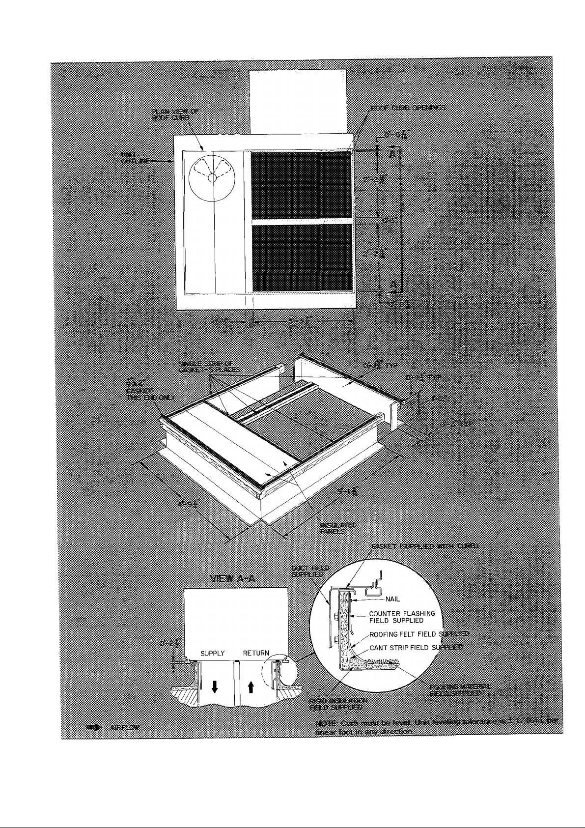
Fig. 2 — 50CD008 Roof Curb Dimensions and Details
Page 4
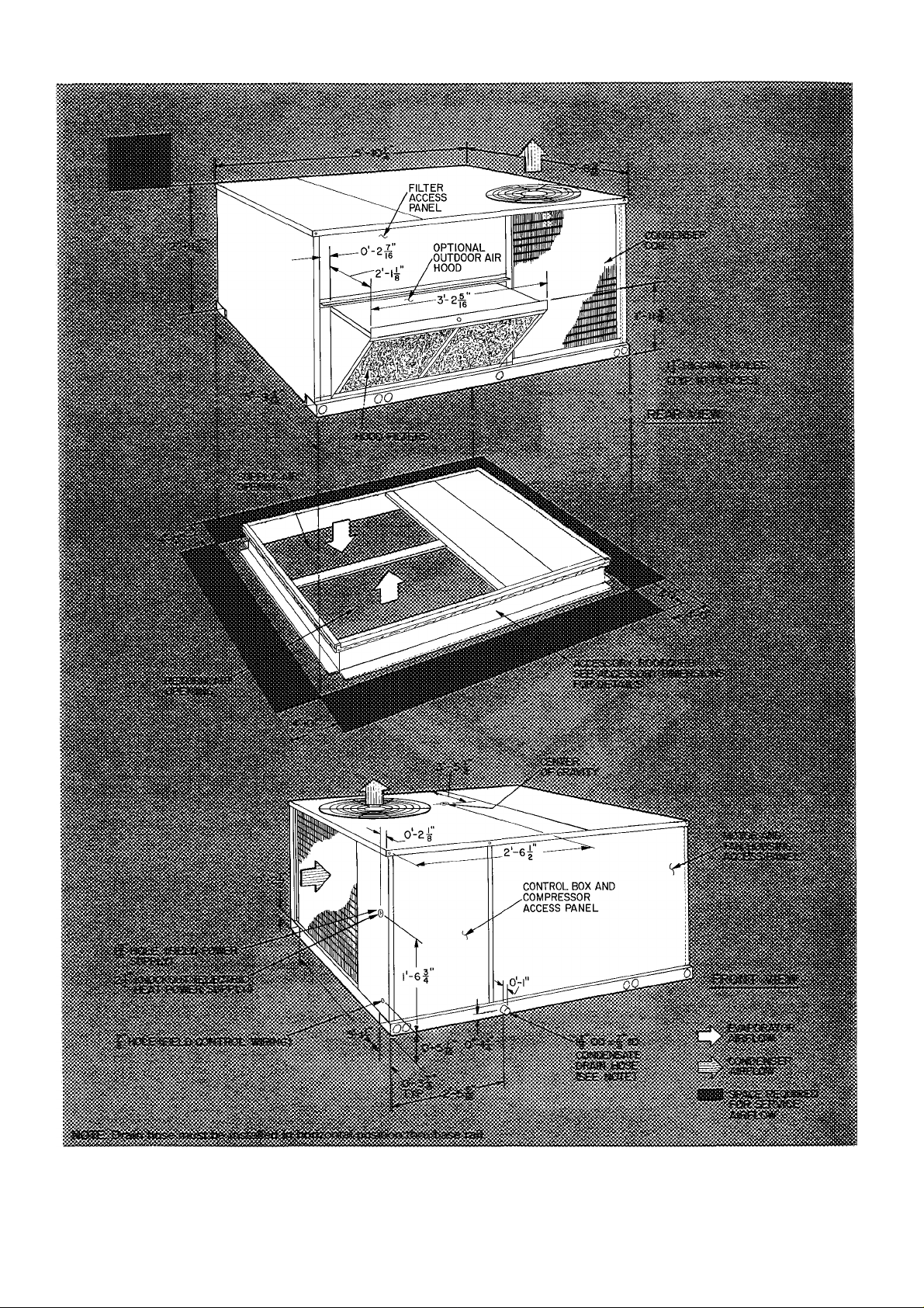
t
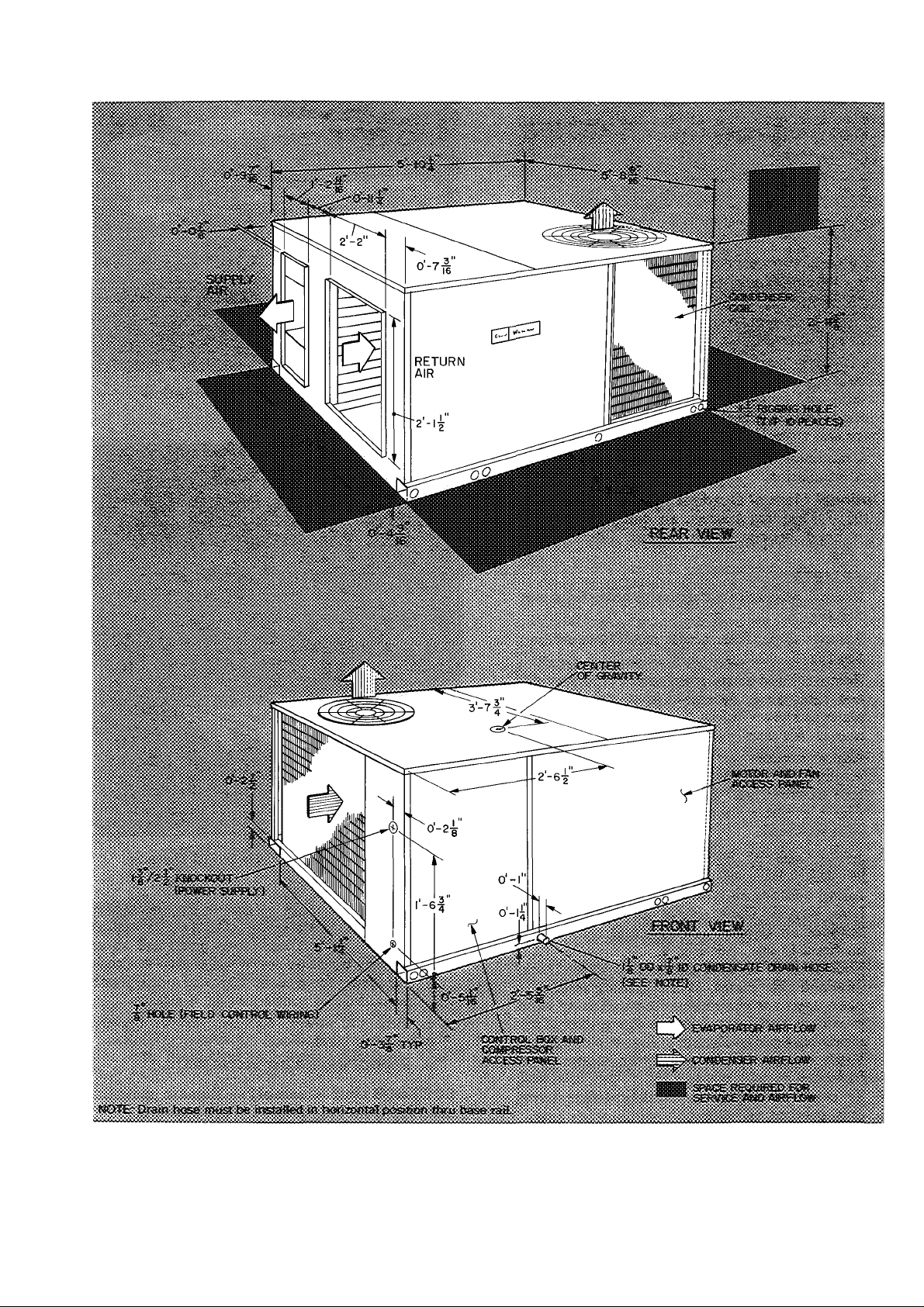
Fig. 3 — 50CD008 Base Unit Dimensions
4
t
Page 5
#
Fig. 4 — 50CH008 Base Unit Dimensions
Page 6

Outdoor Air Intake (50CD008) — The 50CD
can be equipped with an optional outdoor air
damper or an economizer that mixes outdoor air
with return air.
Field-Fabricated Ductwork
50CD — See Fig. 3. Secure all ducts to roof curb and
building structure before unit is placed on curb.
Do not connect ductwork to unit.
Cabinet return air static shall not exceed 0.35 in.
with economzier or 0.40 in. without economizer.
50CH — See Fig. 4. Secure all ductwork to flanges
on unit supply air and return air openings and
building structure.
50CD/CH — Insulate and weatherproof all ex
ternal ductwork, joints and roof/ wall openings with
flashing and mastic in accordance with applicable
codes. Insulate ducts passing thru an unconditioned
space and cover with a vapor barrier.
A minimum clearance is not required for any air
duct installation.
Optional Manual Outdoor Air Damper (50CD
008) — Optional outdoor air damper is shipped
with hood broken down in unit filter section.
See Fig. 5.
ASSEMBLY
1. Remove protective polyethylene cover from unit.
See Fig. 5.
2. Remove upper filter access panel (save screws).
See Fig. 5.
3. Remove hood parts from unit evaporator fan
and filter area. Assemble hood top and side
plates as shown in Fig. 6. Do not attach hood to
unit at this time.
4. Adjust outdoor air damper blade to desired
setting for outside air intake by releasing linkage
rod setscrew and adjusting linkage rod. See
Fig. 7. Secure damper blade in desired position
with setscrew.
5. Remove screws holding manual outdoor air
damper to unit. See Fig. 8.
Install outdoor air hood assembly, using screws
6.
from step 5. These screws secure the manual
outdoor air damper assembly and the outdoor
air hood to unit. See Fig. 9.
Slide outdoor air inlet screens into screen tracks
7.
on hood side plates. While holding screens in
place, fasten screen retainer to hood using screw
provided. Make sure bottom edge of screens rest
inside base rail as shown in Fig. 9.
Replace upper access panel with screws saved
8.
from step 2.
9. To check percentage of ventilation air entering
unit, proceed as follows:
a. If unit power is on, turn it off.
b. Jumper red and black wires in 24-v barrier
in main control box. See Fig. 10.
c. Turn on unit power to energize evaporator
(indoor) fan.
t
Fig. 5 — Access Panel Location
Fig. 6 — Outdoor Air Hood Details
d. Check percentage of ventilation air entering
unit. If percentage varies from that specified,
remove upper filter access panel and adjust
damper blade as described in step 4. Proce
dure may have to be repeated until proper
percentage of ventilation air is attained.
e. Turn off power. Remove jumper between
red and black wires.
f. Replace upper filter access panel.
50CH008 Unit Assembly — Remove packaging
and tape from evaporator fen drive system.
Evaporator Air Fan — Evaporator fan uses a belt-
drive motor which provides high static at nominal
airflow. The standard motor provides approxi
mately 0.95 in. static at nominal cfm and the alter
nate motor provides 1.0 in. static at nominal cfm.
Page 7

#
MANUAL OUTDOOR
air damper assembly
L/NKA6E
ROD SETSCREW
m
a; . •W
Fig. 7 — Damper Blade Adjustment
Fig. 8 — Manual Outdoor Air Damper
HOOD BASE UNIT
Condenser Air Fan and Motor are factory set.
LINKAGE ROD
•>
^,r
AIR SCREENS BASE RAIL
Fig. 9 — Outdoor Air Hood Assembled
to Base Unit (50 Series Shown)
Refer to Service, Condenser Air Fan Adjustment,
as required.
Condensate Drain — See Fig. 3 and 4 for drain
location. A 7/8-in. ID preformed drain hose is
Fig. 10 — Control Box Details
shipped clamped to the evaporator basepan. At
installation, reroute hose so that it passes thru the
hole in the evaporator basepan and the unit base
rail.
When installed properly, the hose protrudes thru
the base rail about 3in. on the 50CD008. On the
50CH008, hose protrudes thru the side of the base
rail about 1 inch.
Replace clamp over the hose where it passes thru
the basepan. This keeps the hose level. Use a trap at
least 4 in. deep and provide protection for trap
against freeze-up.
Field Power Supply — See Fig. 11 and Table 2.
Unit is factory wired for voltage shown on name
plate. On 208-volt installations, reconnect all trans
formers to 208- (200-) volt tap. Refer to unit label
diagrams. Pigtails are provided for field service on
units without electric heat (use factory-supplied
splices or UL-approved copper/aluminum con
nector). Units with electric heat are provided with
terminal block in single point box.
All field wiring must comply with National Elec
trical Code and local requirements.
Run power lines thru condenser coil end panel to
terminal connections as shown on unit wiring
diagram and in Fig. 3 and Fig. 4.
Operating voltage to compressor must be within
voltage range indicated on unit nameplate. On 3phase Units, voltages between phases must be
balanced within 2% and the current must be bal
anced within 10%.
Use the following formula to determine the %
voltage unbalance.
% Voltage Unbalance
_ max voltage deviation from average voltage
average voltage
Page 8

WITHOUT ELECTRIC HEAT
UNIT CONTROL BOX
WITH ELECTRIC HEAT
1
SINGLE POINT BOX
C — Contactor
Comp — Compressor
Gn*d*^ — Equipment Ground
— Fuse
Fu
— Terminal Block
TB
50CD/CH008
NOMINAL
V-PH-HZ
208/230-3-60
460-3-60
— Full Load Amps
FLA
— Horsepower
Hp
— Indoor Fan Motor
IFM
— Locked Rotor Amps
LRA
VOLTAGE
RANGE
Min Max RLA
187
414
. Factory Wiring
. Field Power Wiring
. Field Splice
Fig. 11 — Field Power Wiring Connections
COMPR OFM
LRA FLA
32 5 183 29 1 80
254
91 1 1 5 1 2 9
15 2
508
MOCP — Maximum Overcurrent Protection
OFM — Outdoor Fan Motor
RLA — Rated Load Amps
‘Fuse only
Table 2 — Electrical Data
ELECTRIC HEATERS
IFM
Hp
50CD008
Kw FLA Kw
FLA
9 3 20-23
186 40-46 158
28 1 59-68
9 7 11 7
160 193 160
194 23 4 31 5
29 6 35 7
— —
—
POWER SUPPLY
50CH008 50CD008 50CH008
Min Ckt
j
FLA
93 20-23 55/55 60/60 55/55 60/60
33-38
31 5 68-76 85/95
—
97 11 7
19 3 30
37 9 40
MOCP
55/55 60/60* 55/55 60/60*
60/70 60/70 55/60
80/90
25
25
50
Min Ckt j MOCP
Arr
)ps
95/105 90/100
35*
35 25
35 30
35 55
45
25
60/60
35*
35
35
45
Example; Supply voltage is 460-3-60.
ABC AB = 452 volts
BC = 464 volts
AC = 455 volts
Average Voltage
452 + 464 + 455
3
1371
= 457
Determine maximum deviation from average
voltage: (AB) 457 - 452 = 5 volts
(BC) 464 - 457 = 7 volts
(AC) 457 - 455 = 2 volts
Maximum deviation is 7 volts
Determine % voltage unbalance:
% Voltage Unbalance = 100 x
7
457
= 1.53%
This amount of phase unbalance is satisfactory
as it is below the maximum allowable 2%.
t
Page 9

THERMOSTAT ASSEMBLY
LOW-VOLTAGE THERMOSTAT CONNECTIONS IN UNIT CONTROL BOX
Fig. 12 — Field Control Thermostat Wiring
•#
Unit failure as a result of operation on improper
line voltage or excessive phase imbalance constitutes
abuse and may cause damage to electrical compo
nents. Such operation would invalidate any appli
cable Carrier warranty.
UNITS WITH ELECTRIC HEAT — When elec
tric heat is installed, connect the field power wires
to terminal block located in the single point box.
The single point box is attached to the corner post,
directly below the control box.
DISCONNECTS — A fused disconnect is required
only on units without electric heat. When electric
heat is installed, use a NEC disconnect of adequate
size. Provide fusing for disconnect if required by
local codes. The unit informative nameplate and
Table 2 list electric heat fuse and wire amperage.
Field Control Wiring — Install a Carrier-approved
accessory thermostat assembly according to instal
lation instructions included with accessory. Locate
thermostat assembly on a solid wall in the condi
tioned space to sense average temperature.
THERMOSTAT WIRES — Use 18 gage for 0- to
50-ft long wires, 16 gage for 50- to 75-ft wire
lengths. Route the control wires thru hole provided
in the corner post (see Fig. 3 and 4) and then feed
wires thru a raceway built into the corner post.
Route wires from the raceway into the 24-v barrier
located on the left side of the control box. Make
connections as shown in Fig. 12.
Set heat anticipator settings as indicated below.
Heat Anticipator Settings
1 St stage
2nd Stage with 2 Heaters and 2-Stage
Heat Thermostat*
‘Applies only to 50CD
9
3
Settings may be changed slightly to provide a
greater degree of comfort for a
particular
installation.
Refer to accessory remote control panel instruc
tions as required.
Return Air Filters (50CD008) — Make sure
correct filters are installed in filter tracks. See
Table 1. Do not operate unit without return air
filters.
Outdoor Air Inlet Screens (50CD008) — Out
door air inlet screen(s) must be in place before
operating unit.
Economizer Section (50CD008) — Optional
economizer is shipped with hood broken down in
unit filter section. See Fig. 13.
Fig. 13 — Access Panel Location
ASSEMBLY
1. Remove protective polyethylene cover from
unit. See Fig. 13.
2. Remove upper filter access panel (save screws).
See Fig. 13.
3. Remove hood parts from unit evaporator fan
and filter area. Assemble hood top and side
plates as shown in Fig. 14. Do not attach hood
to unit at this time. Put aside baffle, screen
retainer and retainer screw for later assembly.
4. Determine if vent air is required in building to
be conditioned. If so, check for percentage of
Page 10

vent air needed and record quantity for vent
adjustment in step 11.
5. Remove jumper plug from base unit receptacle
and discard. Insert economizer plug into recep
tacle. See Fig. 15.
Steps 6 thru 8 involve releasing and adjusting
indoor damper blades from factory set position.
Remove violet wire from economizer damper
motor and connect to terminal D on economizer
damper motor. See Fig. 17.
OUTDOOR BLADES (2)
DRIVE
SHAFT
OUTDOOR DRIVE LINKAGE
Fig. 16 — Economizer Details
INDOOR
BLADES (3)
Fig. 14 — Outdoor Air Hood Details
ECONOMIZER
PLUG
CLS — Cooling Lockout Switch
EC — Enthalpy Control
OAT. — Outdoor Air Thermostat
BASE UNIT
RECEPTACLE
OUTDOOR AIR
INLET SCREENS (3)
Fig. 15 — Economizer Installed in Unit
6. Release indoor blades’ drive linkage by loosen
ing linkage connector setscrew at indoor crank-
arm on drive shaft. See Fig. 16.
Remove pink wire from economizer damper
motor terminal D and temporarily tape bare
wire end.
PINK WIRE
VIOLET WIRE
TERMINAL D
Fig. 17 — Economizer Motor Connections
7. Jumper red (base unit 24-v power) and black
(evaporator fan motor) wires in 24-volt control
box compartment. See Fig. 10.
Turn on base unit power to energize evap
orator fan. The economizer’s outdoor blades
should open completely.
8. Adjust the indoor blades’ drive linkage so that
indoor blades are fully closed. Tighten the
linkage connector setscrew. Turn off base unit
power. Reconnect pink and violet wires to
economizer motor, as shown in Fig. 17.
9. If vent air is required, leave red and black wires
jumpered. If vent air is not needed, remove
jumper between red and black wires.
10. Fasten baffle to left side of damper plate with
round head screws provided. See Fig. 18.
t
10
Page 11

BASE RAIL
Fig. 18 — Baffle Installation Details
Fig. 19 — Vent Position Setting Details
11. If vent air is not required, go on to step 12. If
vent air is required, proceed as follows:
a. Turn on base unit power. This energizes the
evaporator fan motor.
b. Slide economizer out of unit so that access
hole to vent position setscrew is visible. See
Fig. 19.
c. Adjust vent opening by loosening vent posi
tion setscrew on left side of economizer
damper motor and setting vent position
lever to adjust damper. See Fig. 19. Move
vent position lever back toward evaporator
coil to close damper or forward to open
damper. When adjustment is eompleted,
retighten setscrew.
d. Turn off base unit power and remove jumper
from red and black wires.
e. Slide economizer assembly back into unit.
12. Remove tape from outdoor air thermostat
(OAT.) and cooling lockout switch (CLS), and
fasten to inside of hood with screws and speed
clips provided. Make sure terminals on OAT.
are up. See Fig. 20.
:i OUTDOOR AIR THERMOSTAT
«(TERMINALS ARE UP)
: COOLING LOCKOUT
SWITCH
1
ACCESSORY
: ENTHALPY,
CONTROL
cooling
LOCKOUT
SWITCH
HOOD
Fig. 20 — Outdoor Air Thermostat/
Enthalpy Control and Cooling Lockout
Switch Installation
11
Page 12

13. Fasten hood top and side plate assembly
(Fig. 9) and eeonomizer to unit with screws
supplied. Before attaching, make sure bottom
of hood assembly is resting on top of unit base
rail.
14. Place knob supplied with accessory economizer
on OAT. See Fig. 20. Set for 3 degrees below
indoor room thermostat setting.
If accessory enthalpy control (EC) (Fig. 20) is
used in lieu of OAT., refer to instructions
shipped with accessory enthalpy control for
installation and adjustment.
15. Connect OAT./EC and CLS per unit label.
See Fig. 21.
Connect 2 economizer wires to each switch
with quick-connects. Unit connecting wires are
shipped taped on outdoor blade. See Fig. 15.
16. Slide outdoor air inlet screens in hood screen
tracks. Secure screens with screen retainer
across hood front. Secure screen retainer with
screw provided. See Fig. 22.
17. Replace upper filter access panel with screws
saved from step 2.
18. Turn base unit power on.
PINK
F
CLS — Cooling Lockout Switch
EC — Enthalpy Control
OAT. — Outdoor Air Thermostat
NOTE; When Enthalpy Control (EC) is installed, outdoor air thermo
stat (OAT ) is removed from economizer
RED
-<T)o^t50-
CLS
-O^Q-
SEE NOTE
_ OAT _
PINK
BLUE
Fig. 21 — Wiring Connections for Outdoor
Air Thermostat/or Enthalpy Control
and Cooling Lockout Switch
AIR INLET SCREEN
RETAINER
OUTDOOR AIR
HOOD
BASE UNIT
BASE RAIL
Fig. 22 — Economizer and Outdoor Air Hood
Assembled to Unit
: *
START-UP
Unit Preparation — Make sure unit has been
installed in accordance with installation instruc
tions and applicable codes.
Compressor Mounting — Compressors are inter
nally spring mounted. Do not loosen or remove
compressor holddown bolts.
Internal Wiring — Check all electrical connections
in unit control boxes. . .tighten as required.
Refrigerant Service Valves — Eaeh unit system
has 2 Schrader type serviee ports, one on the suetion
line and one on the compressor discharge line. Be
sure that eaps on the ports are tight.
Crankcase Heater(s) are energized as long as there
is power to the unit. Energize heater(s) 24 hours
prior to base unit start-up.
Cooling — To start unit, turn on main power
supply. Set system selector switch to COOL and
fan switch at AUTO. Adjust thermostat to a setting
below room temperature. Compressor starts on
closure of contactor.
Check cooling effects at a setting above room
temperature. Cheek unit charge. Refer to Refrig
eration Charge in Service section.
Reset thermostat at a position above room tem
-i
perature. Compressor will shut off.
TO SHUT OFF UNIT — Set system seleetor switch
at OFF position or reset thermostat at a position
above room temperature. Units are equipped with
t
Cyele-LOC™ proteetion device. Unit shuts down on
any safety trip, and indicator light on thermostat
comes on. Cheek reason for safety trip.
Compressor restart is accomplished by manual
reset at the thermostat by turning the seleetor switch
to OFF and then to ON.
Heating — To start unit, turn on main power
supply. Refer to Crankcase Heaters.
Set thermostat at HEAT and a setting above
room temperature, fan at AUTO.
First stage of thermostat energizes the first-stage
eleetric heater; seeond-stage electric heater elements
if installed. Cheek heating effeets at air supply
grille(s).
TO SHUT OFF UNIT — Set system selector switch
at OFF or set heating selector lever below room
temperature.
Ventilation {Continuous Fan) — Set fan and sys
tem selector switches at ON and OFF, respectively.
Evaporator air fan operates continuously to provide
constant air circulation.
Economizer Operation {50CD008) — See
pages 9 thru 12 for start-up and checkout proce
dures. If unit is equipped with modulating out
door air control (economizer), it should operate as
follows;
COOLING MODE — Evaporator and condenser
fans and compressor energize when there is a call
12
Page 13

ф
for cooling and outdoor ambient temperature is
above outdoor air thermostat setting. The econo
mizer damper moves to VENT position.
Evaporator fan starts and economizer damper
opens fully upon a first-stage call for cooling when
outdoor ambient temperature is below the outdoor
air thermostat setting. Compressor remains off.
Compressor is energized and mechanical cooling
integrates with economizer cooling upon a secondstage call for cooling.
Mechanical cooling is locked out when ambient
temperature is below 50 F.
Economizer damper modulates when mixed air
temperature is below mixed air thermostat (non-
adjustable) setting.
An economizer control thermostat (ECT) is
located on the evaporator coil. This thermostat
guards against abnormally low suction tempera
tures while operating mechanical cooling in con
junction with economizer. Low suction tempera
tures can lead to frosting on the evaporator coil.
If frost buildup is detected, thermostat turns off
economizer, thus closing the outdoor air damper.
This raises air temperature entering the evaporator
coil and melts frost. Once frost is melted, the
economizer is re-energized.
During unoccupied periods, if a field-supplied
night switch is used and is opened, the outdoor air
damper closes.
HEATING MODE — Outdoor air damper stays at
VENT position while evaporator air fan runs. If
field-supplied night switch is used, the outdoor air
damper closes when switch is open.
Fig. 23 — Removing Top Panel
ф
SERVICE
Cleaning — Inspect unit interior at the beginning of
each heating and cooling season or as operating
conditions require. Remove unit side panels for
access to unit interior.
EVAPORATOR COIL
1. Turn unit power off.
2. Disconnect evaporator motor and electric
heater(s) from main control box.
3. Remove top panel screws shown in Fig. 23.
4. Remove screws from base of evaporator fan
housing and electric heater plate.
5. Pry up top panel to clear top of evaporator fan
housing. See Fig. 23.
6. Remove evaporator fan housing, heaters and
heater plate from unit.
7. Use commercial coil cleaner (Oakite 164), or
dishwasher detergent in a pressurized spray
cannister. Wash both sides of coil and flush with
clear water. For best results, backflush towards
return air section to remove foreign material.
Flush condensate pan after completion.
8. Replace evaporator fan housing, electric heater(s)
and all wires.
Fig. 24 — Cleaning Condenser Coil
CONDENSER COIL —^ Inspect coil monthly.
Clean condenser coil annually, or as required by
location or outdoor air conditions.
Fins are not continuous thru coil sections. Dirt
and debris may pass thru first section, become
trapped between the 2 rows of fins, and restrict con
denser airflow. Shine flashlight thru coil to deter
mine if dirt or debris has collected between coil
sections.
13
Page 14

Clean coil as follows:
1. Turn off unit power.
2. Remove top panel screws on condenser end of
unit. Remove screws from coil side of coil center
post. Do not remove center post.
3. Remove condenser coil corner post. See Fig. 24.
To hold top panel open, place coil corner post
between top panel and center baffle. See Fig. 25.
4. Remove device holding coil sections together at
return end of condenser coil. Carefully separate
the outer coil section 3 to 4 in. from the inner coil
section. See Fig. 26.
5. Use a water hose or other suitable equipment to
flush down between the 2 coil sections to remove
dirt and debris. Clean the outer surfaces with
a stiff brush in the normal manner.
6. Reposition the outer coil section, remove the coil
corner post from between the top panel and
eenter baffle. Secure the sections together. Install
the corner post, coil center post and replace
all screws.
CONDENSATE DRAIN — Check and clean each
year at start of cooling season. In winter, keep drain
and trap dry or protect against freeze-up.
FILTERS — Clean or replace at start of each heat
ing and cooling season, or more often if operating
conditions require it.
OUTDOOR AIR INLET SCREENS (50CD008) —
Clean screens with steam or hot water and a mild
detergent. Do not use throwaway filters in place of
screens.
Lubrication
COMPRESSORS — Each compressor is charged
with correct amount of oil at the factory.
LAN MOTOR BEARINGS — No lubrication of
condenser or evaporator fan motors is required
for first 5 years of operation.
Annually thereafter, clean and repack bearings
with a suitable bearing grease.
Condenser Air Fan Adjustment (Fig. 27) — Shut
off unit power supply. Remove condenser fan
assembly (grille, motor, motor cover and fan) and
loosen fan hub setscrews. Adjust fan height as
shown in Fig. 27. Tighten setscrews and replace
condenser fan assembly.
Fig. 25 — Propping Up Top Panel
Fig. 26 — Separating Coil Sections
Fig. 27 — Condenser Air Fan Adjustment
Manual Outdoor Air Damper (50CD008) — If
outdoor air damper blade adjustment is required,
see Optional Manual Outdoor Air Damper section
on page 6.
Economizer Adjustment (50CD008) — Refer
to Economizer section under Installation.
Refrigerant Charge — Amount of refrigerant
charge is listed on unit nameplate (also refer to
Table 1). Refer to Carrier Standard Service Tech
niques Manual, Chapter 1, Refrigerants.
Unit panels must be in place when unit is oper
ating during charging procedure.
14
i
Page 15

#
NO CHARGE — Use standard evacuating tech
niques. After evacuating system, weigh in the
specified amount of refrigerant. (Refer to Table 1.)
LOW CHARGE, COOLING — Using Cooling
Charging Chart, Fig. 28, vary refrigerant until the
conditions of the chart are met. Note the charging
chart is different from type normally used. Chart is
based on charging the units to the correct superheat
for the various operating conditions. Accurate pres
sure gage and temperature sensing device are re
quired. Connect the pressure gage to the service port
on the suction line. Mount the temperature
sensing device on the suction line and insulate it so
that outdoor ambient temperature does not affect
the reading. Indoor air cfm must be within the
normal operating range of the unit.
II- r
689
w
¿621-
o
in
0552-
—
§483
in
01414- i 60
bJ
z
o
1—
'"276-
_J
z345-
_ ___ __ _
<n
LiJ
§ 70
in
2 50
90
80
ni ITnnOR TFMP
(F) (C)
115 46
in*s 41
R5 PR
65 18
50 15
45
50
7
TO USE COOLING CHARGING CHART —
Take the outdoor ambient temperature and read the
suction pressure gage. Refer to chart to determine
what suction temperature should he. If suction tem
perature is high, add refrigerant. If suction tempera
ture is low, carefully blow some of the charge. Re
check the suction pressure as charge is adjusted.
Example; 50CD/CH008 (Fig. 28)
Outdoor Temperature ...........................................85 F
Suction Pressure............................................... 70 psig
Suction Temperature should be
............................
52 F
(Suction Temperature may vary ± 5 F.)
30-
207-
20 30 40 50 60 70
SUCTION LINE TEMPERATURE
-7 -i
SUCTION LINE TEMPERATURE
-4
( F)
lb 16 21 27
(C)
80
Fig. 28 — 50CD/CH008 Cooling
Charging Chart
If Chargemaster® charging device is used, tem
perature and pressure readings must be accom
plished using the charging chart.
15
Page 16

t
For replacement items use Carrier Specified Parts
Manufacturer reserves the right to discontinue, or change at any time, specifications or designs without notice and without incurring obligations.
Book
Tab
1 4
1b
6b
Form 50CD-23SI Supersedes 50CD-13SI
Printed in USA 5-83 PC111
Catalog No 565-018
 Loading...