

Page 1

Water-Cooled and Remote Air-Cooled
Indoor Self-Contained Systems and
Water-Cooled Heat Pumps
Installation, Start-Up and
Service Instructions
OMNIZONE™
50BV020-064
CONTENTS
Page
SAFETY CONSIDERATIONS . . . . . . . . . . . . . . . . . . . . .1,2
GENERAL . . . . . . . . . . . . . . . . . . . . . . . . . . . . . . . . . . . . . . . . 2
MAJOR SYSTEM COMPONENTS . . . . . . . . . . . . . . . . . 2
Constant Volume (CV) Units. . . . . . . . . . . . . . . . . . . . . . 2
Variable Air Volume (VAV) Units . . . . . . . . . . . . . . . . . . 2
INSTALLATION . . . . . . . . . . . . . . . . . . . . . . . . . . . . . . . . 3-30
Step 1 — Complete Pre-Installation Checks . . . . . . 3
• EXAMINE THE UNIT
• UNIT STORAGE
• MODULAR UNITS
Step 2 — Rig and Place Unit . . . . . . . . . . . . . . . . . . . . . 3
• REMOVE PACKAGING
• UNIT LOCATION
• UNIT PLACEMENT
• ACOUSTICAL CONSIDERATIONS
• ASSEMBLING MODULAR UNITS
Step 3 — Install Ductwork. . . . . . . . . . . . . . . . . . . . . . . 19
• DUCT STATIC PRESSURE PROBE AND TUBING
( VAV O nl y)
• DUCT HIGH-STATIC (DHS) LIMIT SWITCH (VAV Only)
Step 4 — Make Piping Connections . . . . . . . . . . . . . 21
• CONDENSER WATER PIPING (Water-Cooled Only)
• EVAPORATOR CONDENSATE DRAIN
• HOT WATER HEATING COIL (Optional)
• WATER ECONOMIZER (Optional)
• REMOTE REFRIGERANT PIPING
(Remote Air-Cooled Only)
Step 5 — Complete Electrical Connections. . . . . . 24
• POWER WIRING
• CONTROL WIRING (CV Only)
• REMOTE CONDENSER FAN CONTACTOR WIRING
• CONTROL WIRING (VAV Only)
• SUPPLY AIR TEMPERATURE SENSOR (SAT)
• SMOKE DETECTOR/FIRE ALARM SHUTDOWN (FSD)
• ALARM (ALARM) AND WARNING (WARN) OUTPUTS
• REMOTE OCCUPANCY (ROCC)
• RETURN AIR TEMPERATURE SENSOR (RAS)
START-UP . . . . . . . . . . . . . . . . . . . . . . . . . . . . . . . . . . . . 30-48
General . . . . . . . . . . . . . . . . . . . . . . . . . . . . . . . . . . . . . . . . . 30
• CRANKCASE HEATERS
• CONFIRM THE INPUT POWER PHASE SEQUENCE
• INTERNAL WIRING
• RETURN-AIR FILTERS
• COMPRESSOR MOUNTING
• REFRIGERANT SERVICE PORTS
CV Unit Start-Up . . . . . . . . . . . . . . . . . . . . . . . . . . . . . . . . 31
• EVAPORATOR FAN
•COOLING
• HEATING (Heat Pump Units Only)
VAV Unit Start-Up . . . . . . . . . . . . . . . . . . . . . . . . . . . . . . . 42
• PERFORM AUTOMATIC RUN TEST
•CHECK VFD
• POWER UP LID DISPLAY
• LOG ON TO THE LID DISPLAY
Page
• CHANGE THE DEFAULT PASSWORD
• SET THE CLOCK
• CONFIGURE SCHEDULES
• PROGRAM SET POINTS
• CHECK SYSTEM PARAMETERS
• DISPLAY ALARM HISTORY
• CONFIGURE THE CUSTOM PROGRAMMING
SELECTIONS
• SET CONTROLLER ADDRESS
• LOG OFF FROM THE CONTROLLER
Sequence of Operation (CV Only) . . . . . . . . . . . . . . . 47
• WATER ECONOMIZER COOLING
Sequence of Operation (VAV Only) . . . . . . . . . . . . . . 48
• SUPPLY FAN
• COMPRESSOR COOLING
• WATER ECONOMIZER COOLING
• COOLING RESET
Diagnostic Features (CV Only) . . . . . . . . . . . . . . . . . . 48
VAV Control and VFD Diagnostics. . . . . . . . . . . . . . . 48
SERVICE . . . . . . . . . . . . . . . . . . . . . . . . . . . . . . . . . . . . . . . . 49
Compressor Rotation . . . . . . . . . . . . . . . . . . . . . . . . . . . 49
Fan Motor Replacement. . . . . . . . . . . . . . . . . . . . . . . . . 49
MAINTENANCE . . . . . . . . . . . . . . . . . . . . . . . . . . . . . . 49-51
Cleaning Unit Exterior. . . . . . . . . . . . . . . . . . . . . . . . . . . 49
Coil Cleaning. . . . . . . . . . . . . . . . . . . . . . . . . . . . . . . . . . . . 49
Inspection. . . . . . . . . . . . . . . . . . . . . . . . . . . . . . . . . . . . . . . 49
Air Filters . . . . . . . . . . . . . . . . . . . . . . . . . . . . . . . . . . . . . . . 49
Condensate Drains. . . . . . . . . . . . . . . . . . . . . . . . . . . . . . 49
Water-Cooled Condensers . . . . . . . . . . . . . . . . . . . . . . 49
• GRAVITY FLOW METHOD
• FORCED CIRCULATION METHOD
Fan Motor Lubrication. . . . . . . . . . . . . . . . . . . . . . . . . . . 50
Fan Bearing Lubrication . . . . . . . . . . . . . . . . . . . . . . . . 50
Fan Sheaves . . . . . . . . . . . . . . . . . . . . . . . . . . . . . . . . . . . . 50
•ALIGNMENT
Evaporator Fan Performance Adjustment . . . . . . . 51
• BELT TENSION ADJUSTMENT
Charging the System. . . . . . . . . . . . . . . . . . . . . . . . . . . . 51
• REMOTE AIR-COOLED UNITS
Compressor Oil . . . . . . . . . . . . . . . . . . . . . . . . . . . . . . . . . 51
TROUBLESHOOTING . . . . . . . . . . . . . . . . . . . . . . . . 51-65
Forcing and Clearing an Input or Output
(VAV only) . . . . . . . . . . . . . . . . . . . . . . . . . . . . . . . . . . . . 54
START-UP CHECKLIST . . . . . . . . . . . . . . . . . . .CL-1, CL-2
SAFETY CONSIDERATIONS
Installing, starting up, and servicing air-conditioning
components and equipment can be dangerous. Only trained,
qualified installers and service mechanics should install, startup, and service this equipment.
When working on the equipment, observe precautions in
the literature and on tags, stickers, and labels attached to the
Manufacturer reserves the right to discontinue, or change at any time, specifications or designs without notice and without incurring obligations.
Catalog No. 04-53500001-01 Printed in U.S.A. Form 50BV-3SI Pg 1 10-08 Replaces: 50BV-2SI
Page 2
equipment. Follow all safety codes. Wear safety glasses and
work gloves.
WARNING
The 50BV units have removable access panels for easy
servicing. These panels allow access to controls, compressors,
condensers, VFD(s) (if applicable), evaporator motors, blowers, belts, pulleys, and refrigeration components.
Before performing service or maintenance operations on
unit, turn off main power switch to unit and open all disconnects. More than one disconnect switch may be
required to deenergize this equipment. Electric shock hazard can cause injury or death.
CAUTION
Use care in handling, rigging, and setting bulky equipment.
GENERAL
Omnizone™ 50BV indoor packaged units are very flexible
for a variety of applications. These self-contained units are
available as water-cooled or remote air-cooled air conditioning
units. The 50BV units are available with either constant volume (CV) or variable air volume (VAV) controls. In addition,
the 50BV unit is available as a water-cooled heat pump. Finally, Omnizone 50BV units are available in two cabinet styles.
Nominal 18 through 30-ton units are constructed in a singlepiece, unpainted galvanized cabinet. Nominal 30 through
60-ton units are available as modular units, and can be taken
apart for easier installation. Modular units are built using an unpainted, galvanized steel cabinet with steel framework, and can
be easily disassembled without breaking the refrigerant lines.
See Table 1 for a model number reference by application.
Each unit contains multiple scroll compressors piped in
separate refrigerant circuits. Each water-cooled circuit includes
a coaxial (tube-in-tube) condenser, TXV (thermostatic expansion valve), individual evaporator coils, and all interconnecting
piping. Water-cooled units are shipped fully charged with
refrigerant. Remote air-cooled units are shipped with a nitrogen
holding charge.
Each unit is equipped with one or two forward-curved centrifugal blowers, to ensure quiet air delivery to the conditioned
space. Constant volume units operate at a single, adjustable fan
speed and provide zone temperature control using a standard
commercial thermostat. For VAV applications, the unit is supplied with a variable frequency drive(s) (VFD) that automatically adjusts blower speed to maintain a constant, adjustable
duct static pressure. Compressors are automatically staged to
provide supply air temperature control (VAV applications) or
zone temperature control using a two-stage commercial thermostat (CV applications).
MAJOR SYSTEM COMPONENTS
Constant Volume (CV) Units
MAIN CONTROL BOARD (MCB) — The main control
board for the 50BVC, E, Q, T, U, and V units provides both
controls and diagnostics including:
• Condensate Overflow Protection
prevents unit operation in
the event that the drain pan clogs (optional sensors
required).
• Random Start
provides a programmable start with a range
of 30 to 60 seconds.
• Anti-short Cycle Timer
provides a 5-minute delay to pre-
vent compressor short cycling.
• Low Pressure Bypass Timer
bypasses the low-pressure
switch for 90 seconds to avoid nuisance trips during cold
start-up.
• High Pressure Switch Delay
is a one-second delay that pre-
vents nuisance trips at start-up.
• Brownout/Surge/Power Interruption Protection
is a
20-second moving scale that works in conjunction with the
random start timer to delay unit start when a nuisance lockout would otherwise have occurred. This allows the water
pumps to restart and establish water flow.
• Alarm Output
contacts provide remote fault indication.
• Test/Service Pin is a jumper that reduces all time delay
settings to 6 seconds during troubleshooting or operation
verification.
• Reset
occurs after a 5-minute delay when a fault condition
occurs. When the timer expires, the unit will restart. If the
same condition occurs a second time, the unit will be locked
out.
• Lockout Reset
requires that the unit power be cycled at the
unit controller via either the thermostat or unit disconnect.
NOTE: The refrigerant circuits on dual compressor models
are completely independent. If either stage has a fault condition the remaining stage will continue to operate without
interruption. A freeze (optional sensor required) or condensate
overflow lockout will shut down both refrigerant circuits.
• LEDs
are provided for diagnostic purposes.
Variable Air Volume (VAV) Units — The 50BVJ, K,
W, and X units come equipped with a Carrier 6400 Comfort
Controller and a VFD. Refer to the 50BV,XJ Controls, Operation and Troubleshooting manual for details.
NOTE: The VAV units utilize face split coils and should not
be operated below 50% of nominal airflow to prevent coil
freezing.
Table 1 — Model Number Reference By Application Type
MODEL TYPE* AVAILABLE CAPACITY CONSTRUCTION CONTROLS
50BVC Water-Cooled 18 to 30 nominal tons Single-piece CV
50BVE Remote Air-Cooled 18 to 30 nominal tons Single-piece CV
50BVQ Water-Cooled Heat Pump 18 to 30 nominal tons Single-piece CV
50BVJ Water-Cooled 18 to 30 nominal tons Single-piece VAV
50BVK Remote Air-Cooled 18 to 30 nominal tons Single-piece VAV
50BVT Water-Cooled 30 to 60 nominal tons Modular CV
50BVU Remote Air-Cooled 30 to 60 nominal tons Modular CV
50BVV Water-Cooled Heat Pump 30 to 60 nominal tons Modular CV
50BVW Water-Cooled 30 to 60 nominal tons Modular VAV
50BVX Remote Air-Cooled 30 to 60 nominal tons Modular VAV
LEGEND
CV — Constant Volume
VAV — Variable Air Volume
*All units are cooling only unless specified.
2
Page 3
INSTALLATION
Omnizone™ 50BV units are intended for indoor installation only. Determine building alterations required to run piping,
wiring, and ductwork. Read all installation instructions before
installing the unit.
Step 1 — Complete Pre-Installation Checks
EXAMINE THE UNIT — Examine the unit for shipping
damage. File a claim with the transit company if damage is
found. Check the shipment for completeness. Verify that the
nameplate electrical requirements match the available power
supply.
UNIT STORAGE — The 50BV units are designed and packaged for indoor storage and use only. If the equipment is not
needed for immediate installation upon its arrival at the job site,
it should be left in its shipping carton and stored in a clean, dry
area. Units must only be stored or moved in the normal upright
position, as indicated by the “UP” arrows on each carton, at all
times. DO NOT STACK UNITS.
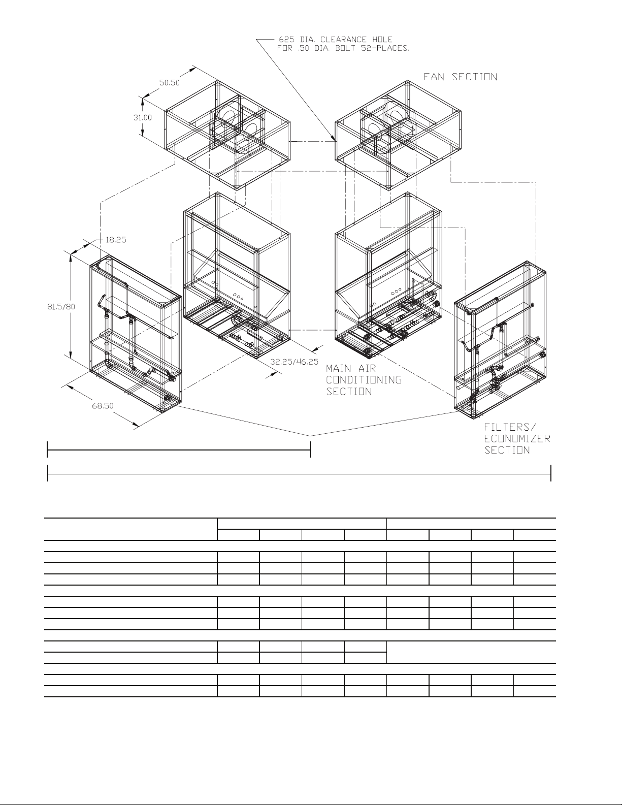
MODULAR UNITS — The 50BVT,U,V,W,X units are shipped
in multiple sections for easy movement and installation. The
separate modules will pass through a standard 36-in. steelframed door or service elevator. Circuit integrity is maintained
because none of the refrigerant piping requires disconnection.
Water piping connections are made with the use of heavy-duty
bronze-bodied unions so no field welding or brazing is required.
See Table 2 for the number of sections per unit.
Table 2 — Modular Unit Shipping Table
NUMBER OF SECTIONS
SECTIONS
Main Air Conditioning
Weight (lb) (each)
Reheat Coil Option
Weight (lb) (each)
Economizer/Filter
Filter Section Weight (lb)
Economizer Weight (lb)
Fan Section
Weight (lb) (each)
Tot al U ni t
Weight (lb)
50BVT, U, V, W, X
034 044 054 064
1
2100218252220022225
1
40
1
310
200
1
650
4
3300854008615086150
2
40
2
310
200
2
650
2
40
2
310
200
2
650
2
40
2
310
200
2
650
For single piece units, use spreader bars and rigging straps if
lifting with a crane to avoid damage to the unit. Otherwise,
move with a fork truck using the shipping pallet.
Refer to Fig. 2-14 for unit dimensions.
Refer to Tables 3A and 3B for physical data.
REMOVE PACKAGING — Remove all protective plastic,
remove and discard unit top cover protector, filter cover,
controller display protector, and water piping connection
packaging.
UNIT LOCATION — Locate the unit in an indoor area
that allows easy removal of the filters, access panels, and
accessories. Make certain enough space is available for service
personnel to perform maintenance or repairs. Provide sufficient
room to make all water, duct, and electrical connections. If the
unit is located in a small mechanical equipment room, make
sure adequate space is available for air to return freely to the
unit. These units are not approved for outdoor installations and
must be installed inside the structure. Do not locate in areas
that are subject to freezing.
UNIT PLACEMENT — Ensure that the floor is structurally
strong enough to support the weight of the equipment with
minimum deflection. A good, level floor is required for proper
unit operation and to ensure proper fit-up and alignment of all
bolt together and union coupled modules on modular units.
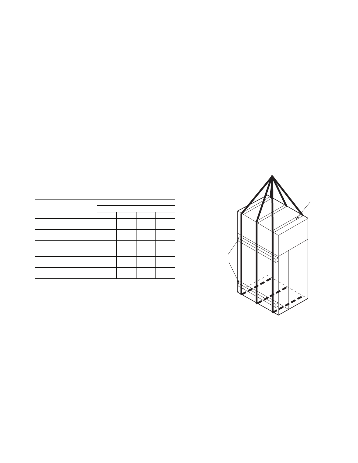
a50-7257ef
USE
SPREADER
BAR TO
PREVENT
DAMAGE
TO UNIT
4 X 4 ABOVE
AND BELOW
RETURN DUCT
CONNECTIONS
NOTE: Units ship with the main air conditioning, economizer/
filter, and, when selected, the reheat coil sections assembled
together. These can be easily disassembled, as required, in the
field. The fan section(s) always ships separately.
Step 2 — Rig and Place Unit — Use proper lifting
and handling practices to avoid damage to the unit. Move
modular units with a fork truck using the baserails provided, or
use spreader bars and lifting straps as shown in Fig. 1.
Fig. 1 — Modular Unit Rigging
3
Page 4
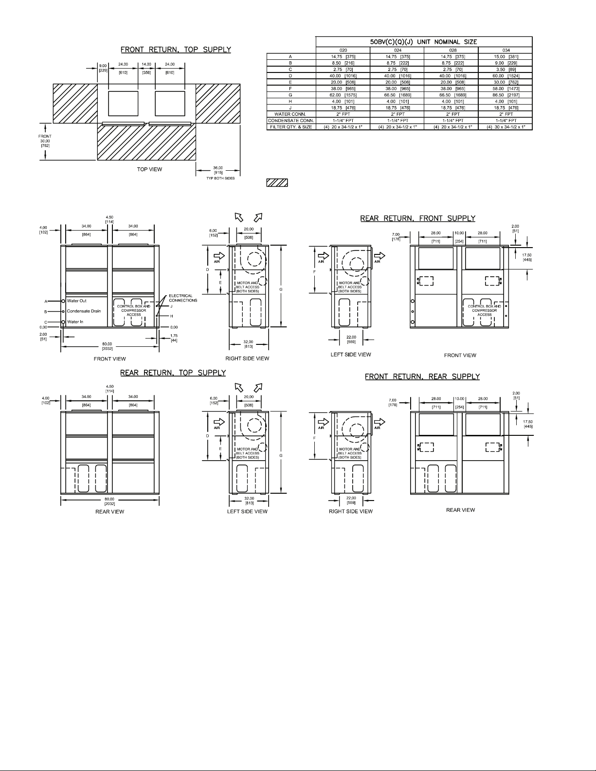
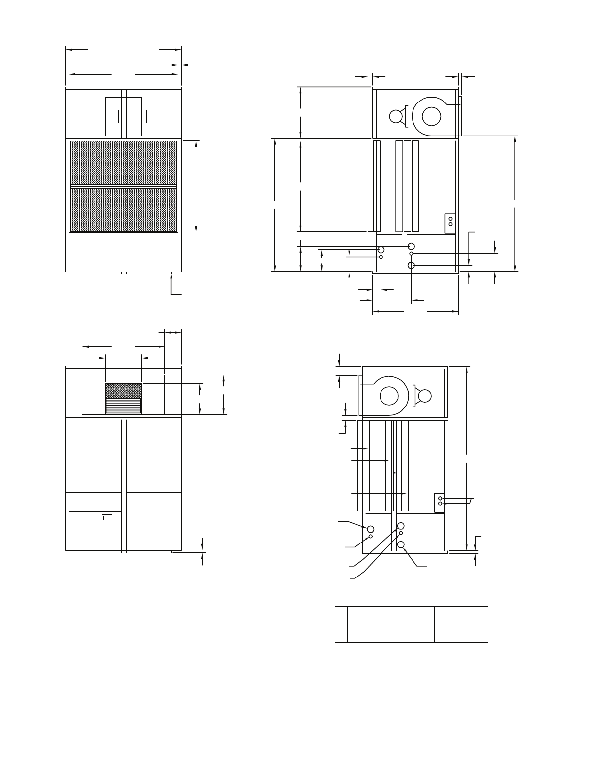
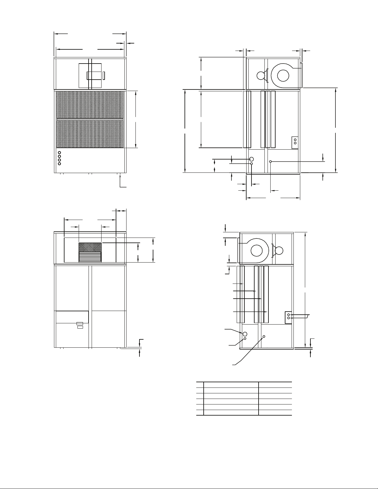
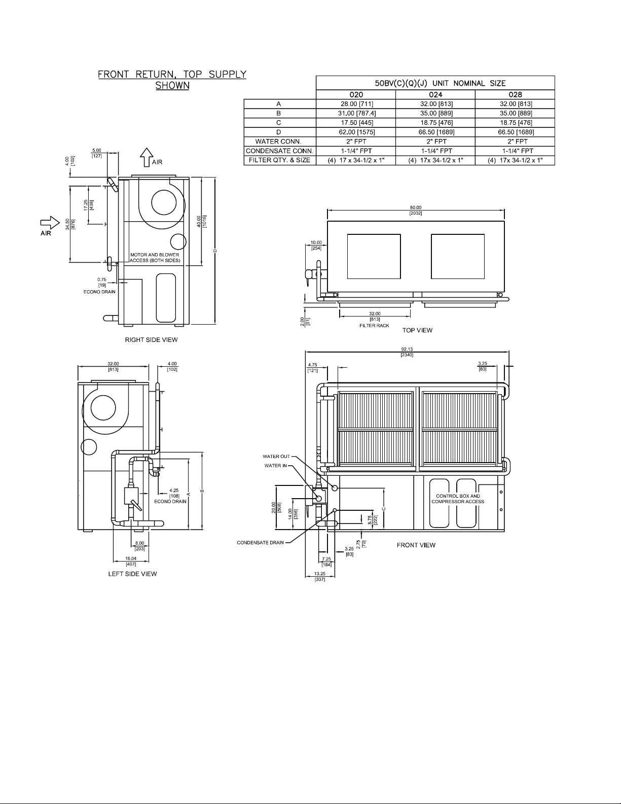
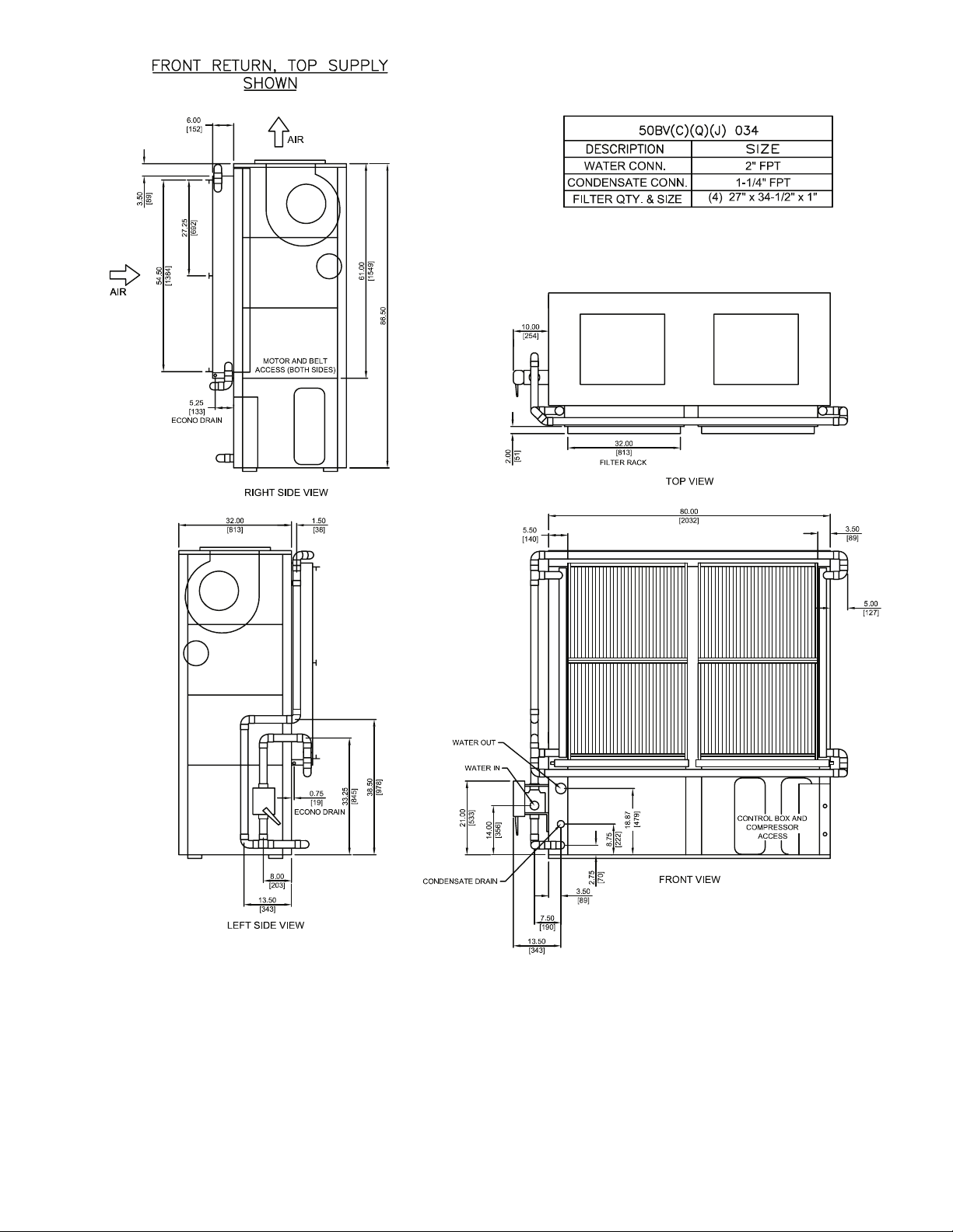
NOTES:
1. Dimensions in inches [mm].
2. VAV models (50BVJ) are rear return, top supply only.
3. Compressor, controls, and condenser access are through front panels.
4. Field power connections are 1-3/4 inches. Control connections are 7/8 inches.
5. Optional blower orientation is selected in model number nomenclature as option 9 in FIOP section
(digits 15 and 16).
Shows recommended minimum service clearances.
OPTIONAL
BLOWER
ORIENTATION
OPTIONAL
BLOWER
ORIENTATION
STANDARD
BLOWER
ORIENTATION
STANDARD
BLOWER
ORIENTATION
Fig. 2 — 50BVC,J,Q020-034 Dimensions
4
a50-8199
Page 5
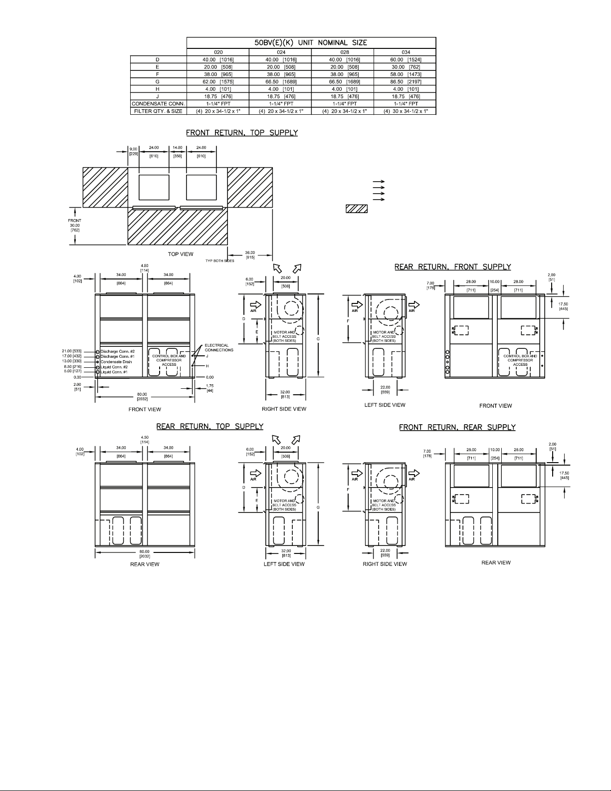
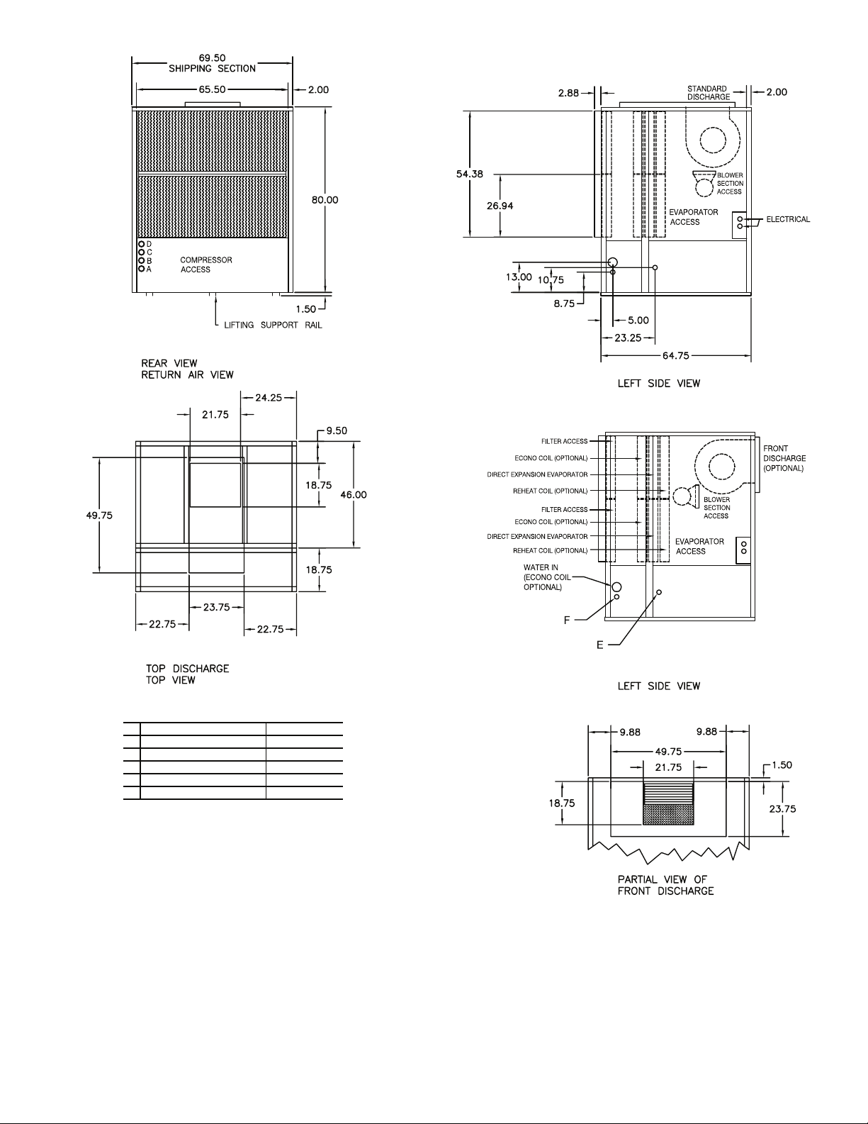
NOTES:
1. Dimensions in inches [mm].
2. VAV models (50BVK) are rear return, top supply only.
3. Compressor, controls, and condenser access are through front panels.
4. Field power connections are 1-3/4 inches. Control connections are 7/8 inches.
5. Discharge (hot gas) connections are 1-1/8 in. OD.
6. Liquid line connections are 7/8 in. OD.
7. Optional blower orientation is selected in model number nomenclature as
option 9 in FIOP section (digits 15 and 16).
RECOMMENDED CONDENSER MATCHES:
50BV020 one (1) 09DK020 (50/50 split each)
50BV024 one (1) 09DK024 (50/50 split each)
50BV028 one (1) 09DK028 (50/50 split each)
50BV034 one (1) 09DK034 (50/50 split each)
Shows recommended minimum service clearances.
OPTIONAL
BLOWER
ORIENTATION
OPTIONAL
BLOWER
ORIENTATION
STANDARD
BLOWER
ORIENTATION
STANDARD
BLOWER
ORIENTATION
Fig. 3 — 50BVE,K020-034 Dimensions
5
a50-8200
Page 6
69.50
SHIPPING SECTION
65.50
BLOWER
SECTION
ACCESS
2.00
54.75
31.00
54.38
2.88
BLOWER
SECTION
ACCESS
EVAPORATOR
ACCESS
2.00
STANDARD
DISCHARGE
COMPRESSOR
ACCESS
REAR VIEW
RETURN AIR VIEW
EVAPORATOR
ACCESS
49.75
21.75
9.88
EVAPORATOR
ACCESS
LIFTING SUPPORT RAIL
23.75
18.75
80.00
15.00
REAR DISCHARGE
(Optional)
FILTER ACCESS
ECONO COIL (Optional)
DIRECT EXPANSION
EVAPORATOR
13.00
3.19
5.50
8.75
5.00
23.25
51.63
LEFT SIDE VIEW
EVAPORATOR
ACCESS
BLOWER
SECTION
ACCESS
81.50
3.75
10.75
111.00
ELECTRICAL BOX
ELECTRICAL BOX
ACCESS
COMPRESSOR
ACCESS
1.50
FRONT VIEW
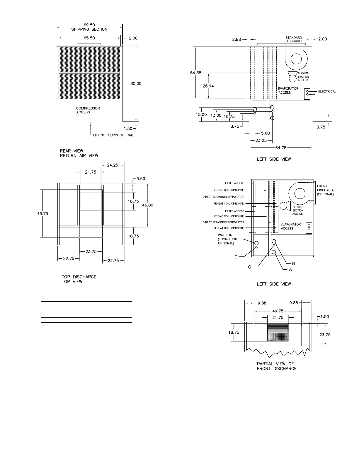
NOTES:
1. Dimensions in inches.
2. All units are rear return airflow configuration.
3. Constant volume units are available with front or rear air supply.
4. VAV units (50BVW) are available with rear supply only.
5. Recommended minimum service clearances are as follows:
a. Front and rear — 30 in. (762 mm)
b. Left or right side — 65 in. (1651 mm) for coil removal
c. Side opposite coil removal — 20 in. (508 mm)
Fig. 4 — 50BVT,V,W034 (High-Boy) Dimensions
a50-8201
REHEAT COIL (Optional)
WATER IN
(ECONO COIL
OPTIONAL)
6
ELECTRICAL
1.50
D
A
B
C
CONNECTIONS
A WATER OUT 2-1/2 in. FPT
B WATER IN 2-1/2 in. FPT
C CONDENSATE DRAIN 1-1/4 in. FPT
D ECONOMIZER DRAIN 1-1/4 in. FPT
REPLACEMENT FILTERS : EIGHT (8) AT 17 x 27 x 4 INCHES.
LEFT SIDE VIEW
Page 7
CONNECTIONS
A WATER OUT 2-1/2 in. FPT
B WATER IN 2-1/2 in. FPT
C CONDENSATE DRAIN 1-1/4 in. FPT
D ECONOMIZER DRAIN 1-1/4 in. FPT
REPLACEMENT FILTERS : EIGHT (8) AT 17 x 27 x 4 INCHES.
NOTES:
1. Dimensions in inches.
2. All units are rear return airflow configuration.
3. Recommended minimum service clearances are as follows:
a. Front and rear — 30 in. (762 mm)
b. Left or right side — 65 in. (1651 mm) for coil removal
c. Side opposite coil removal — 20 in. (508 mm)
Fig. 5 — 50BVT,V,W034 (Low-Boy) Dimensions
a50-8202
a50-8202.eps
7
Page 8
69.50
SHIPPING SECTION
2.00 2.00
69.50
SHIPPING SECTION
4.00
65.50 65.50
BLOWER
SECTION
ACCESS
BLOWER
SECTION
ACCESS
54.75
80.00
31.00
54.38
2.88
BLOWER
SECTION
ACCESS
EVAPORATOR
ACCESS
2.00
STANDARD
DISCHARGE
81.50
COMPRESSOR
ACCESS
REAR VIEW
RETURN AIR VIEW
9.88
19.75
COMPRESSOR
ACCESS
LIFTING SUPPORT RAIL
49.75
21.75
EVAPORATOR
ACCESS
ELECTRICAL BOX
ELECTRICAL BOX
ACCESS
EVAPORATOR
ACCESS
COMPRESSOR
ACCESS
EVAPORATOR
ACCESS
ELECTRICAL BOX
ELECTRICAL BOX
ACCESS
139.00
FRONT VIEW
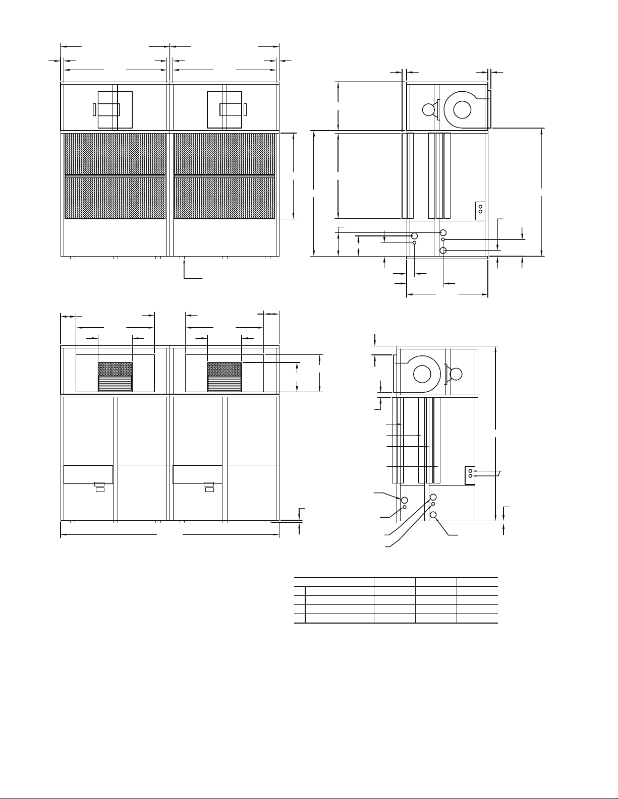
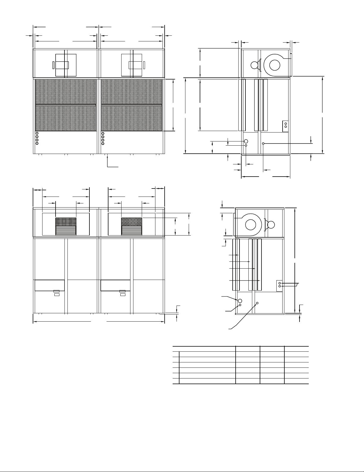
NOTES:
1. Dimensions in inches.
2. All units are rear return airflow configuration.
3. CV units are available with front or rear air supply.
4. VAV units (50BVW) are available with rear supply only.
5. Recommended minimum service clearances are as follows:
a. Front and rear — 30 in. (762 mm)
b. Left and right sides — 65 in. (1651 mm) for coil removal
a50-8203
49.75
21.75
9.88
EVAPORATOR
ACCESS
COMPRESSOR
ACCESS
15.00
13.00
8.75
5.00
23.25
51.63
LEFT SIDE VIEW
18.75
23.75
5.50
REAR DISCHARGE
(OPTIONAL)
BLOWER
SECTION
ACCESS
3.19
FILTER ACCESS
ECONO COIL (OPTIONAL)
DIRECT EXPANSION
EVAPORATOR
REHEAT COIL (OPTIONAL)
WATER IN
(ECONO COIL
1.50
OPTIONAL)
EVAPORATOR
ACCESS
D
B
A
C
LEFT SIDE VIEW
CONNECTIONS
UNIT SIZE 044 054 064
A WATER OUT 2-1/2 in. FPT 3 in. FPT 3 in. FPT
B WATER IN 2-1/2 in. FPT 3 in. FPT 3 in. FPT
C CONDENSATE DRAIN 1-1/4 in. FPT 1-1/4 in. FPT 1-1/4 in. FPT
D ECONOMIZER DRAIN 1-1/4 in. FPT 1-1/4 in. FPT 1-1/4 in. FPT
REPLACEMENT FILTERS : SIXTEEN (16) AT 17 x 27 x 4 INCHES.
3.75
10.75
111.00
ELECTRICAL
1.50
Fig. 6 — 50BVT,V,W044-064 (High-Boy) Dimensions
8
Page 9
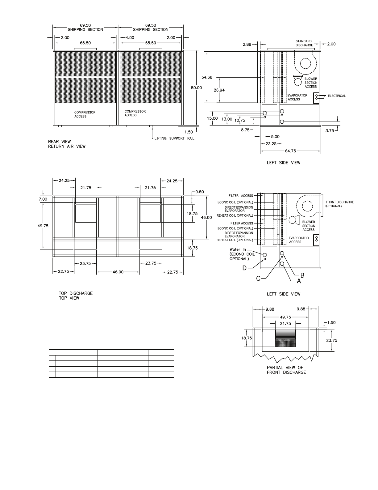
NOTES:
1. Dimensions in inches.
2. All units are rear return airflow configuration.
3. Recommended minimum service clearances are as follows:
a. Front and rear — 30 in. (762 mm)
b. Left and right sides — 65 in. (1651 mm) for coil removal
CONNECTIONS
UNIT SIZE 044 054 064
A WATER OUT 2-1/2 in. FPT 3 in. FPT 3 in. FPT
B WATER IN 2-1/2 in. FPT 3 in. FPT 3 in. FPT
C CONDENSATE DRAIN 1-1/4 in. FPT 1-1/4 in. FPT 1-1/4 in. FPT
D ECONOMIZER DRAIN 1-1/4 in. FPT 1-1/4 in. FPT 1-1/4 in. FPT
REPLACEMENT FILTERS : SIXTEEN (16) AT 17 x 27 x 4 INCHES.
Fig. 7 — 50BVT,V,W044-064 (Low-Boy) Dimensions
a50-8204
9
Page 10
69.50
SHIPPING SECTION
65.50
BLOWER
SECTION
ACCESS
2.00
54.75
31.00
54.38
2.88
BLOWER
SECTION
ACCESS
EVAPORATOR
ACCESS
2.00
STANDARD
DISCHARGE
D
C
COMPRESSOR
B
ACCESS
A
REAR VIEW
RETURN AIR VIEW
EVAPORATOR
ACCESS
ELECTRICAL BOX
49.75
21.75
9.88
EVAPORATOR
ACCESS
LIFTING SUPPORT RAIL
23.75
18.75
80.00
13.00
REAR DISCHARGE
(Optional)
FILTER ACCESS
ECONO COIL (Optional)
DIRECT EXPANSION
EVAPORATOR
REHEAT COIL (Optional)
3.19
5.50
8.75
5.00
23.25
51.63
LEFT SIDE VIEW
EVAPORATOR
ACCESS
BLOWER
SECTION
ACCESS
81.50
10.75
111.00
ELECTRICAL
ELECTRICAL BOX
ACCESS
COMPRESSOR
ACCESS
1.50
FRONT VIEW
NOTES:
1. Dimensions in inches.
2. All units are rear return airflow configuration.
3. Constant volume units are available with front or rear air supply.
4. VAV units (50BVX) are available with rear supply only.
5. Recommended condenser match is ONE (1) 09DK034 (50/50 split).
6. Use proper piping practice for remote refr igerant connections. Refer to
Carrier System Design Manual Part 3.
7. Recommended minimum service clearances are as follows:
a. Front and rear — 30 in. (762 mm)
b. Left or right side — 65 in. (1651 mm) for coil removal
c. Side opposite coil removal — 20 in. (508 mm)
Fig. 8 — 50BVU,X034 (High-Boy) Dimensions
WATER IN
(ECONO COIL
OPTIONAL)
F
E
CONNECTIONS
A LIQUID LINE CIRCUIT 1 7/8 in. OD
B LIQUID LINE CIRCUIT 2 7/8 in. OD
C DISCHARGE LINE CIRCUIT 1 1-1/8 in. OD
D DISCHARGE LINE CIRCUIT 2 1-1/8 in. OD
E CONDENSATE DRAIN 1-1/4 in. FPT
F ECONOMIZER DRAIN 1-1/4 in. FPT
REPLACEMENT FILTERS : EIGHT (8) AT 17 x 27 x 4 INCHES.
10
LEFT SIDE VIEW
1.50
a50-8205
Page 11
CONNECTIONS
A LIQUID LINE CIRCUIT 1 7/8 in. OD
B LIQUID LINE CIRCUIT 2 7/8 in. OD
C DISCHARGE LINE CIRCUIT 1 1-1/8 in. OD
D DISCHARGE LINE CIRCUIT 2 1-1/8 in. OD
E CONDENSATE DRAIN 1-1/4 in. FPT
F ECONOMIZER DRAIN 1-1/4 in. FPT
REPLACEMENT FILTERS : EIGHT (8) AT 17 x 27 x 4 INCHES.
NOTES:
1. Dimensions in inches.
2. All units are rear return airflow configuration.
3. Recommended condenser match is ONE (1) 09DK034 (50/50 split).
4. Use proper piping practice for remote refrigerant connections. Refer to
Carrier System Design Manual Part 3.
5. Recommended minimum service clearances are as follows:
a. Front and rear — 30 in. (762 mm)
b. Left or right side — 65 in. (1651 mm) for coil removal
c. Side opposite coil removal — 20 in. (508 mm)
Fig. 9 — 50BVU,X034 (Low-Boy) Dimensions
a50-8206
a50-8206
11
Page 12
69.50
SHIPPING SECTION
2.00 2.00
69.50
SHIPPING SECTION
4.00
65.50 65.50
BLOWER
SECTION
ACCESS
BLOWER
SECTION
ACCESS
54.75
80.00
31.00
54.38
2.88
BLOWER
SECTION
ACCESS
EVAPORATOR
ACCESS
2.00
STANDARD
DISCHARGE
81.50
D
C
COMPRESSOR
B
A
ACCESS
REAR VIEW
RETURN AIR VIEW
9.88
49.75
21.75
EVAPORATOR
ACCESS
ELECTRICAL BOX
ELECTRICAL BOX
ACCESS
EVAPORATOR
ACCESS
COMPRESSOR
ACCESS
19.75
EVAPORATOR
ACCESS
ELECTRICAL BOX
ELECTRICAL BOX
ACCESS
D
C
COMPRESSOR
B
A
ACCESS
LIFTING SUPPORT RAIL
49.75
21.75
EVAPORATOR
ACCESS
COMPRESSOR
ACCESS
139.00
FRONT VIEW
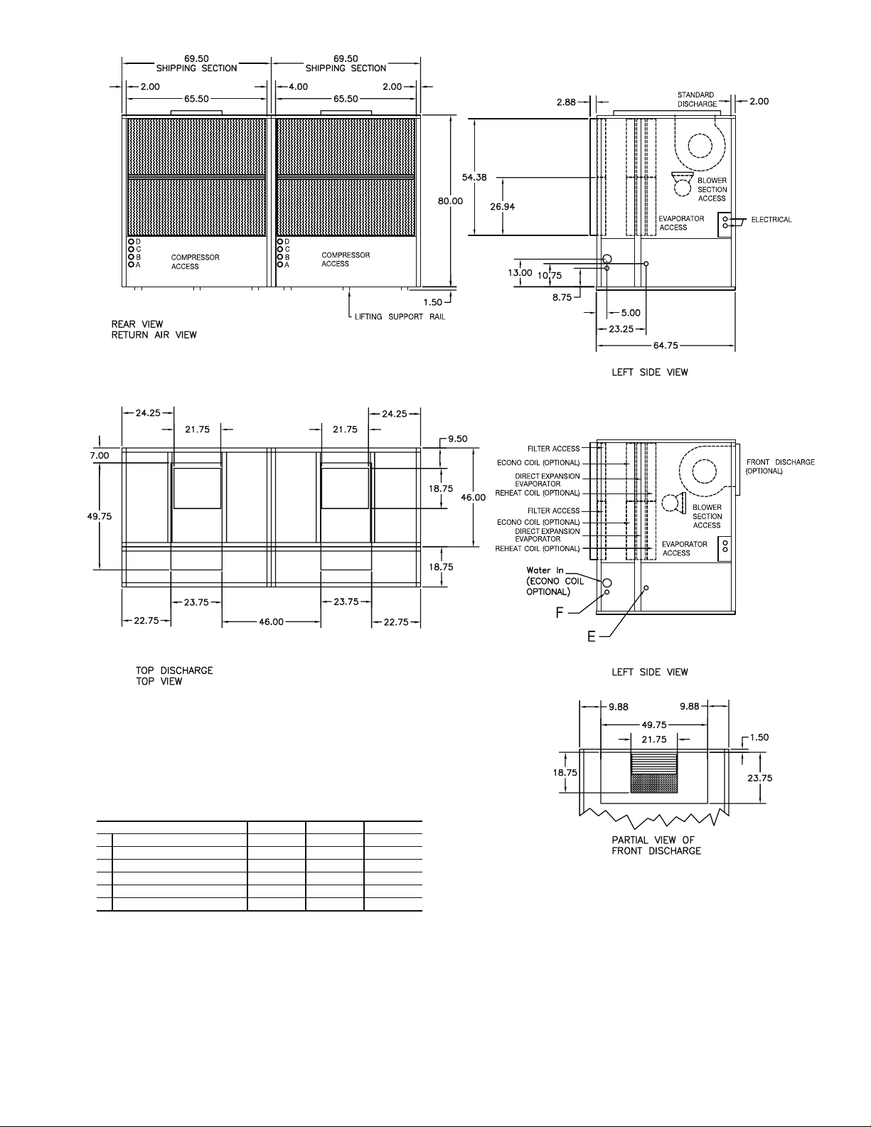
NOTES:
1. Dimensions in inches.
2. All units are rear return airflow configuration.
3. CV units are available with front or rear air supply.
4. VAV units (50BVX) are available with rear supply only.
5. Use proper piping practice for remote refrigerant connections. Refer to
Carrier System Design Manual Part 3.
6. Recommended minimum service clearances are as follows:
a. Front and rear — 30 in. (762 mm)
b. Left and right sides — 65 in. (1651 mm) for coil removal
a50-8207
9.88
13.00
8.75
5.00
23.25
51.63
LEFT SIDE VIEW
18.75
23.75
5.50
REAR DISCHARGE
(OPTIONAL)
BLOWER
SECTION
ACCESS
3.19
FILTER ACCESS
ECONO COIL (OPTIONAL)
DIRECT EXPANSION
EVAPORATOR
REHEAT COIL (OPTIONAL)
WATER IN
(ECONO COIL
1.50
OPTIONAL)
EVAPORATOR
ACCESS
111.00
F
E
CONNECTIONS
UNIT SIZE 044 054 064
A LIQUID LINE CIRCUIT 1, 2 7/8 in. OD 7/8 in. OD 7/8 in. OD
B LIQUID LINE CIRCUIT 3, 4 7/8 in. OD 7/8 in. OD 7/8 in. OD
C DISCHARGE LINE CIRCUIT 1, 2 1-1/8 in. OD 1-1/8 in. OD 1-1/8 in. OD
D DISCHARGE LINE CIRCUIT 3, 4 1-1/8 in. OD 1-1/8 in. OD 1-1/8 in. OD
E CONDENSATE DRAIN 1-1/4 in. FPT 1-1/4 in. FPT 1-1/4 in. FPT
F ECONOMIZER DRAIN 1-1/4 in. FPT 1-1/4 in. FPT 1-1/4 in. FPT
REPLACEMENT FILTERS : SIXTEEN (16) AT 17 x 27 x 4 INCHES.
LEFT SIDE VIEW
10.75
ELECTRICAL
1.50
Fig. 10 — 50BVU,X044-064 (High-Boy) Dimensions
12
Page 13
NOTES:
1. Dimensions in inches.
2. All units are rear return airflow configuration.
3. Use proper piping practice for remote refrigerant connections. Refer to
Carrier System Design Manual Part 3.
4. Recommended minimum service clearances are as follows:
a. Front and rear — 30 in. (762 mm)
b. Left and right sides — 65 in. (1651 mm) for coil removal
CONNECTIONS
A LIQUID LINE CIRCUIT 1, 2 7/8 in. OD 7/8 in. OD 7/8 in. OD
B LIQUID LINE CIRCUIT 3, 4 7/8 in. OD 7/8 in. OD 7/8 in. OD
C DISCHARGE LINE CIRCUIT 1, 2 1-1/8 in. OD 1-1/8 in. OD 1-1/8 in. OD
D DISCHARGE LINE CIRCUIT 3, 4 1-1/8 in. OD 1-1/8 in. OD 1-1/8 in. OD
E CONDENSATE DRAIN 1-1/4 in. FPT 1-1/4 in. FPT 1-1/4 in. FPT
F ECONOMIZER DRAIN 1-1/4 in. FPT 1-1/4 in. FPT 1-1/4 in. FPT
REPLACEMENT FILTERS : SIXTEEN (16) AT 17 x 27 x 4 INCHES.
UNIT SIZE 044 054 064
Fig. 11 — 50BVU,X044-064 (Low-Boy) Dimensions
a50-8208
13
Page 14
NOTES:
1. Dimensions in inches [mm].
2. Refer to base unit certified drawing for additional unit dimensions, service
clearance, and alternate airflow configurations.
a50-7306ef
Fig. 12 — 50BVC,J,Q020-028 with Optional Waterside Economizer Dimensions
14
Page 15
NOTES:
1. Dimensions in inches [mm].
2. Refer to base unit certified drawing for additional unit dimensions, service
clearances, and alternate airflow configurations.
a50-7307ef
Fig. 13 — 50BVC,J,Q034 with Optional Waterside Economizer Dimensions
15
Page 16
a50-8235
*
*
Size 034 Units
Size 044-064 Units
Shipping Weights (lb)
50BVT,U,V,W,X UNIT
MAIN AIR CONDITIONING SECTION (EACH)
NUMBER OF SECTIONS 12221222
SECTION WEIGHT 1450 1175 1550 1575 2100 1825 2200 2225
REHEAT COIL OPTION 40 40 40 40 40 40 40 40
FILTER/ECONOMIZER SECTION (EACH)
NUMBER OF SECTIONS 12221222
FILTER SECTION 310 310 310 310 310 310 310 310
ECONOMIZER OPTION 200 200 200 200 200 200 200 200
FAN SECTION (EACH)
NUMBER OF SECTIONS 1222
FAN SECTION 650 650 650 650
TOTAL UN IT
NUMBER OF SECTIONS 36662444
UNIT WITH OPTIONS 2650 4750 5500 5550 2650 4750 5500 5550
*High-boy/low-boy.
034 044 054 064 034 044 054 064
Fig. 14 — Modular Shipping Weights — 50BVT,U,V,W,X
HIGH-BOY UNIT LOW-BOY UNIT
AIR CONDITIONING SECTION
INCLUDED IN
16
Page 17

Table 3A — Physical Data — 50BVC,E,J,K,Q
UNIT 50BVC,E,J,K,Q 020 024 028 034
NOMINAL CAPACITY (Tons) 18 20 25 30
OPERATING WEIGHT (lb)
50BVC,Q…50BVJ 1192…1227 1378…1413 1428…1473 1680…1725
50BVE…50BVK 1110…1145 1290…1325 1320…1365 1520…1565
COMPRESSOR Copeland Scroll
Quantity 2222
Number of Refrigerant Circuits 2222
Oil (ounces) Ckt 1…Ckt 2 85…85 110…110 110…110 140…140
REFRIGERANT TYPE R-22 or R-410A
Expansion Device TXVTXVTXVTXV
Operating Charge (lb) Ckt 1…Ckt 2 8.1…8.1 9.1…9.1 9.1…9.1 18.0…18.0
CONDENSER (50BVC,Q,J only) Tube-in-Tube Coaxial
Quantity of Manifolded Circuits 2222
Nominal Flow Rate (GPM) 54 60 75 90
Water Flow Range (GPM) 36-72 40-80 50-100 60-120
Max. Water Working Pressure (PSIG) 400 400 400 400
Max. Refrig. Working Pressure (PSIG) 450 (600*) 450 (600*) 450 (600*) 450 (600*)
Min. Entering Water Temp. (°F) 50 50 50 50
Max. Entering Water Temp. (°F) 110 110 110 110
Waterside Volume (gal) 3.6 4.0 5.0 6.0
EVAPORATOR COIL
Rows…Fins/in. 3…14 3…14 3…14 3…14
Total Face Area (sq ft) 18.1 18.1 18.1 22.0
EVAPORATOR FAN
Quantity…Size 2…15x15 2…15x15 2…15x15 2…15x15
Type Drive Belt Belt Belt Belt
Nominal CFM 7200 8000 10,000 12,000
Std Motor Qty…HP…Frame Size 2…1.5…56 2…2…56H 2…3…56HZ 2…5…56HZ
Alt 1 Motor Qty…HP…Frame Size 2…2…56H 2…3…56HZ 2…5…56HZ —
Alt 2 Motor Qty…HP…Frame Size 2…3…56HZ 2…5…56HZ — —
Alt 3 Motor Qty…HP…Frame Size 2…5…56HZ — — —
Motor Nominal RPM (1.5, 2, 3, HP) 1725 1725 1725 —
Motor Nominal RPM (5 HP) 3450 3450 3450 3450
Fan Drive RPM Range
Std Fan Drive (1.5, 2, 3 HP) 753-952 753-952 753-952 —
Std Fan Drive (5 HP) 967-1290 967-1290 967-1290 967-1290
Med Static Fan Drive (1.5, 2, 3 HP) 872-1071 872-1071 872-1071 —
Motor Bearing Type Ball Ball Ball Ball
Maximum Allowable RPM 1300 1300 1300 1300
Motor Pulley Pitch Diameter
Std Fan Drive (1.5, 2, 3 HP) 3.7-4.7 3.7-4.7 3.7-4.7 —
Std Fan Drive (5 HP) 2.9-3.9 2.9-3.9 2.9-3.9 2.9-3.9
Med Static Fan Drive (1.5, 2, 3 HP) 4.3-5.3 4.3-5.3 4.3-5.3 —
Motor Shaft Diameter (in.) (1.5, 2 HP)
Motor Shaft Diameter (in.) (3, 5 HP)
Belt, Qty…Type…Length (in.)
Std Fan Drive (1.5, 2 HP) 1…B…39 1…B…39 — —
Std Fan Drive (3 HP) 2…B…39 2…B…39 2…B…39 —
Std Fan Drive (5 HP) 2...BX…42 2...BX…42 2...BX…42 2...BX…42
Med Static Fan Drive (1.5, 2 HP) 1…B…40 1…B…40 — —
Med Static Fan Drive (3 HP) 2…B…40 2…B…40 2…B…40 —
Pulley Center Line Distance (in.) 10.1…10.9 10.1…10.9 10.1…10.9 10.1…10.9
Speed Change Per Full Turn of
Moveable Pulley Flange (RPM)
Std Fan Drive (1.5, 2, 3 HP) 33 33 33 —
Std Fan Drive (5 HP) 54 54 54 54
Med Static Fan Drive (1.5, 2, 3 HP) 33 33 33 —
Fan Shaft Diameter (in.) 1111
5
/
8
7
/
8
HIGH PRESSURE SWITCHES (PSIG)
Cutout 380 (420*) ± 10 380 (420*) ± 10 380 (420*) ± 10 380 (420*) ± 10
Reset (Auto) 300 (420*) ± 15 300 (420*) ± 15 300 (420*) ± 15 300 (420*) ± 15
LOW PRESSURE SWITCHES (PSIG)
Cutout 20 (40*) ± 3 20 (40*) ± 3 20 (40*) ± 3 20 (40*) ± 3
Reset (Auto) 40 (60*) ± 5 40 (60*) ± 5 40 (60*) ± 5 40 (60*) ± 5
REMOTE REFRIGERANT CONNECTIONS
(50BVE,K Only)
Discharge (Hot Gas) Connection (in.) Qty…Size 2…1
Liquid Connection (in.) Qty…Size 2…7/
1
/
8
8
RETURN AIR FILTERS
Quantity…Size (in.) 4…20x34.5x1 4…20x34.5x1 4…20x34.5x1 4…30x34.5x1
LEGEND *R-410A models.
TXV — Thermostatic Expansion Valve
5
/
8
7
/
8
2…11/
2…7/
——
7
/
8
8
8
2…11/
2…7/
8
8
7
/
8
2…11/
2…7/
8
8
17
Page 18
Table 3B — Physical Data — 50BVT,U,V,W,X
UNIT 50BVT,U,V,W,X 034 044 054 064
NOMINAL CAPACITY (Tons) 30 40 50 60
OPERATING WEIGHT (lb)
50BVT,V…50BVW 2580…2645 4334…4404 5198…5298 5230…5330
50BVU…50BVX 2420…2485 4094…4164 4938…5038 4970…5070
COMPRESSOR Copeland Scroll
Quantity 2444
Number of Refrigerant Circuits 2444
Oil (oz.)
Circuit 1…Circuit 2 140…140 110…110 140…140 140…140
Circuit 3…Circuit 4 — 110…110 140…140 140…140
REFRIGERANT TYPE R-22
Expansion Device TXV TXV TXV TXV
Operating Charge (lb)
Circuit 1…Circuit 2 18.0…18.0 10.0…10.0 18.0…18.0 18.0…18.0
Circuit 3…Circuit 4 — 10.0…10.0 18.0…18.0 18.0…18.0
CONDENSER (50BVT,V,W only) Tube-in-Tube Coaxial
Quantity of Manifolded Circuits 2444
Nominal Flow Rate (GPM) 90 120 150 180
Water Flow Range (GPM) 60-120 80-160 100-200 120-240
Max. Water Working Pressure (PSIG) 400 400 400 400
Max. Refrig. Working Pressure (PSIG) 450 450 450 450
Min. Entering Water Temp. (°F) 50 50 50 50
Max. Entering Water Temp. (°F) 110 110 110 110
Waterside Volume (gal) 6.0 9.0 11.3 13.5
EVAPORATOR COIL
Rows…Fins/in. 4…12 3…12 4…12 4…12
Total Face Area (sq ft) 23.2 46.4 46.4 46.4
EVAPORATOR FAN
Quantity…Size 1…18x18 2…18x18 2…18x18 2…18x18
Type Drive Belt Belt Belt Belt
Nominal CFM 12,000 16,000 20,000 24,000
Motor Option 1 Qty…HP…Frame Size 1…7.5…213T 2…7.5…213T 2…7.5…213T 2…7.5…213T
Motor Option 2 Qty…HP…Frame Size 1…10…215T 2…10…215T 2…10…215T 2…10…215T
Motor Option 3 Qty…HP…Frame Size 1…15…254T 2…15…254T 2…15…254T 2…15…254T
Motor Option 4 Qty…HP…Frame Size 1…20…256T — 2…20…256T 2…20…256T
Motor Nominal RPM 1750 1750 1750 1750
Fan Drive RPM Range
Standard (7.5 HP) 780-960 780-960 780-960 780-960
Standard (10, 15, 20 HP), Med Static (7.5 HP) 805-991 805-991 805-991 805-991
Med Static (10, 15, 20 HP), High Static (7.5 HP) 960-1146 960-1146 960-1146 960-1146
High Static (10, 15, 20 HP) 1119-1335 1119-1335 1119-1335 1119-1335
Motor Bearing Type Ball Ball Ball Ball
Maximum Allowable RPM 1450 1450 1450 1450
Motor Pulley Pitch Diameter
Std Fan Drive (7.5 HP) 5.2-6.4 5.2-6.4 5.2-6.4 5.2-6.4
Std Fan Drive (10, 15, 20 HP), Med Static (7.5 HP) 4.8-6.0 4.8-6.0 4.8-6.0 4.8-6.0
Med Static Fan Drive (10, 15, 20 HP), High Static (7.5 HP) 5.8-7.0 5.8-7.0 5.8-7.0 5.8-7.0
High Static Fan Drive (10, 15, 20 HP) 5.8-7.0 5.8-7.0 5.8-7.0 5.8-7.0
Motor Shaft Diameter (in.) (7.5, 10 HP) 1
Motor Shaft Diameter (in.) (15, 20 HP) 15/
Belt, Qty…Type…Length (in.)
Std Fan Drive (7.5 HP) 2…B…48 2...B...48 2…B…48 2…B…48
Std Fan Drive (10, 15, 20 HP), Med Static (7.5 HP) 2…B…46 2…B…46 2…B…46 2…B…46
Med Static Fan Drive (10, 15, 20 HP), High Static 7.5 HP) 2…B…48 2…B…48 2…B…48 2…B…48
High Static Fan Drive (10, 15, 20 HP) 2…B…45 2…B…45 2…B…45 2…B…45
Pulley Center Line Distance (in.) 10.2-11.4 10.2-11.4 10.2-11.4 10.2-11.4
Speed Change Per Full Turn of Moveable Pulley Flange (RPM)
Std Fan Drive (7.5 HP) 36 36 36 36
Std Fan Drive (10, 15, 20 HP), Med Static (7.5 HP) 31 31 31 31
Med Static Fan Drive (10, 15, 20 HP), High Static (7.5 HP) 31 31 31 31
High Static Fan Drive (10, 15, 20 HP) 36 36 36 36
Fan Shaft Diameter (in.) 1
HIGH PRESSURE SWITCHES (PSIG)
Cutout 380 ± 10 380 ± 10 380 ± 10 380 ± 10
Reset (Auto) 300 ± 15 300 ± 15 300 ± 15 300 ± 15
LOW PRESSURE SWITCHES (PSIG)
Cutout 20 ± 3 20 ± 3 20 ± 3 20 ± 3
Reset (Auto) 40 ± 5 40 ± 5 40 ± 5 40 ± 5
REMOTE REFRIGERANT CONNECTIONS (50BVU,X Only)
Discharge (Hot Gas) Connection (in.) Qty…Size 2…1
Liquid Connection (in.) Qty…Size 2…7/
RETURN AIR FILTERS
Quantity…Size (in.) 8…17x27x4 16…17x27x4 16…17x27x4 16…17x27x4
3
/
8
8
7
/
16
1
/
8
8
13/
15/
17/
16
4…11/
4…7/
8
8
8
8
13/
15/
17/
16
4…11/
4…7/
8
8
8
8
13/
15/
17/
4…11/
4…7/
8
8
16
8
8
18
Page 19
ACOUSTICAL CONSIDERATIONS — Proper acoustical
considerations are a critical part of every system’s design and
operation. Each system design and installation should be
reviewed for its own unique requirements. For job specific
requirements, contact an acoustical consultant for guidance and
recommendations.
In general, to reduce noise, consider the following:
• Locate mechanical room and ducts away from noise
sensitive locations. Whenever possible, work with the
architect to locate the equipment rooms around the
perimeters of restrooms, hallways, fire escapes, stair
wells, etc., to reduce noise transmission. This allows not
only for isolation from radiated sound but also enables
the contractor to route duct systems around sensitive
locations.
• Construct the equipment room of concrete block or use a
double offset stud wall with interwoven insulation. Seal
all penetrations.
• Design the system for low total static pressure.
• Use suitable vibration isolation pads or isolation springs
according to the design engineer's specifications.
• A flexible canvas duct connector is recommended on
both the supply and return air sides of units to be
connected to system ductwork.
• Use a minimum of 15 ft of return ductwork between the
last air terminal or diffuser and the unit.
• Insulate supply and return ducts with 2-in., 3-lb density
insulation.
• Round duct is recommended. If rectangular ductwork is
used, keep aspect ratios as small as possible (i.e., as close
to square as possible).
• Avoid any direct line of sight from return air grilles
into the unit's return. If return air is to be ducted to an
equipment room, an elbow should be installed within the
equipment room.
• Running a return air drop to near the floor of the room
will aid in sound attenuation.
• Do not exceed the recommended supply duct velocity of
2,000 fpm.
• Do not exceed the recommended return duct velocity of
1,000 fpm.
• Use turning vanes on 90-degree elbows.
• Place isolation springs under each corner and under each
compressor if utilized.
ASSEMBLING MODULAR UNITS — 50BVT,U,V,W,X
30 to 60 ton units ship in the number of pieces shown in Table
2. Reassemble the unit. Use the loose hardware provided in the
main air-conditioning section and the instructions below.
1. The filter/economizer section ships bolted to the main airconditioning section and can be removed in the field.
When reattaching the filter/economizer section to the
main air-conditioning section, place the filter side of the
filter/economizer section facing out and away from the
main air conditioning section.
2. If the unit has 2 filter/economizer and 2 main airconditioning sections (40 through 60 ton units), bolt the
remaining filter/economizer section and main airconditioning section together, as in Step 1.
3. For units with 2 filter/economizer and 2 main airconditioning sections, use the provided unions to assemble the water connections between the 2 additional
sections joined in Step 2.
4. For units with multiple air conditioning sections, connect
the condensate drain hoses from the “B” side of the unit
to the drain manifold on the “A” side of the unit.
5. For unit sizes 044-064, connect power wiring from the
main terminal block in the “A” side of the unit to the
power terminal block in the “B” side of the unit.
6. For VAV units only, connect the plenum tubing, coiled
behind the VAV control panel, to the bulkhead fittings
located in the discharge of the supply fan. This connects
the high pressure supply to the high side of the duct high
static pressure switch.
CAUTION
Remove all shipping blocks, if any, under blower housing
or damage to the fan may occur.
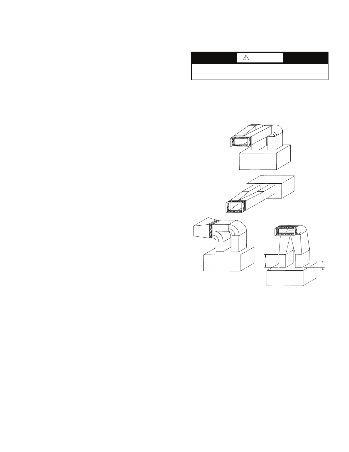
Step 3 — Install Ductwork — The VAV units must
use a “pair of pants” configuration as shown in Fig. 15. Refer
to the Carrier System Design Manual or ASHRAE (American
Society of Heating, Refrigerating and Air Conditioning Engineers) standards for the recommended duct connection to unit
with 2 fans.
A
NOTE: A = 11/2 to 21/2B
Fig. 15 — Typical Fan Discharge Connections for
Multiple Fan Units
A supply air outlet collar and return air duct flange are provided on all units to facilitate duct connections. Refer to dimensional drawings (Fig. 2-14) for connection sizes and locations.
A flexible canvas duct connector is recommended on both
supply and return air sides of the units to be connected to the
system ductwork.
All metal ductwork should be adequately insulated to avoid
heat loss or gain and to prevent condensation from forming on
the duct walls. Uninsulated ductwork is not recommended, as
the unit's performance will be adversely affected.
Do not connect discharge ducts directly to the blower
outlet(s). The factory filter should be left in place on a free
return system.
If the unit will be installed in a new installation, the duct
system should be designed in accordance with the System Design Manual, Part 2 and with ASHRAE (American Society of
Heating, Refrigeration and Air Conditioning Engineers) procedures for duct sizing. If the unit will be connected to an existing
duct system, check that the existing duct system has the capacity to handle the required airflow for the unit application at an
a50-8357.eps
B
19
Page 20
acceptable system static pressure. If the existing duct system is
too small, larger ductwork must be installed.
The duct system and diffusers should be sized to handle the
design airflow volumes quietly. To maximize sound attenuation
of the unit's blower(s), the supply and return air plenums should
be insulated for a length of at least 15 ft from the unit. Direct line
of sight from return air grilles into the unit's return should be
avoided. If return air is to be ducted to an equipment room, an
elbow should be installed within the equipment room. Running a
return air drop to near the floor of the room will aid in sound
attenuation. Avoid transmitting vibrations generated by the
movement of air in the ducting to the walls of the building. This
is especially important where ductwork penetrates walls. The
maximum recommended return air velocity is 1,000 fpm. Lower
return air velocities will result in lower sound power levels. The
use of round supply duct plenums should be considered, as it
will significantly reduce low frequency sound at the equipment
room. If rectangular supply plenums are used, the aspect ratio of
the duct should be kept as small as possible (i.e., as close to
square as possible). The large, flat surface areas associated with
large aspect ratio duct systems will transmit sound to the space,
and the potential for duct-generated noise is increased. The maximum recommended supply air duct velocity is 2,000 fpm.
Units with two fans should have a properly designed “pair
of pants” duct connection. An adequate straight length of
ducting from the unit should be allowed before elbows are
installed. If connecting an elbow directly to the fan outlet, a
minimum straight length of 2 fan diameters from the fan outlet
is recommended. Elbows should turn in the direction of fan rotation, if possible. Abrupt turns will generate air turbulence and
excessive noise. Turning vanes should be used in all short radius bends. Ensure that ducting does not obstruct access to the
unit for routine servicing.
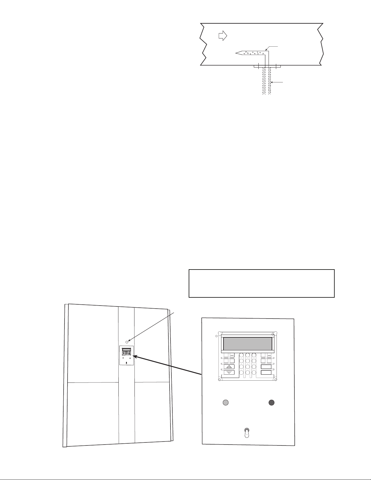
DUCT STATIC PRESSURE PROBE AND TUBING (VAV
Only) — On VAV systems, the duct static pressure sensor and
tubing are field-mounted. The sensor tubing sensing point
should be located near the end of the main supply trunk duct in
a position free from turbulence effects and at least 10 duct diameters downstream and 4 duct diameters upstream from any
major transitions or branch take-offs. Incorrectly placing the
sensing point could result in improper operation of the entire
VAV s y st e m .
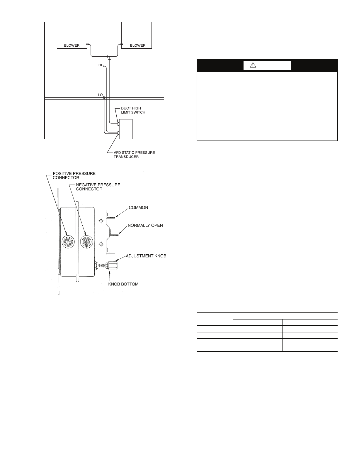
Install the factory-supplied duct static pressure probe with
the tip facing into the airflow. See Fig. 16.
AIRFLOW
PROBE
a50-7138ef
TUBING
Fig. 16 — Duct Static Pressure Probe
(P/N 39EK20462)
1
Use
/4-in. OD approved polyethylene tubing for up to
50 ft (3/8-in. OD for 50 to 100 ft) to connect the probe to the
bulkhead fitting mounted above the unit display panel
(Fig. 17). Carefully route the tubing from the probe to this
bulkhead fitting.
The static pressure control should be adjusted so that, at full
airflow, all of the remote VAV terminal boxes receive the
minimum static pressure required plus any downstream resistance. Control the system to the lowest static pressure set point
that will satisfy airflow requirements. Lower static pressure set
points reduce total required brake horsepower and reduce
generated sound levels.
DUCT HIGH-STATIC (DHS) LIMIT SWITCH (VAV
Only) — The duct high static limit switch is a mechanical
safety that prevents duct overpressurization. The switch is located on the side of the VAV low voltage control panel
(Fig. 18) and is factory set at 3 in. wg. To make an adjustment
using an accurate differential pressure gage, connect low side
and high side to gage and pressure source. Place a voltmeter
across common and normally open contacts. Rotate the adjustment knob (Fig. 19) clockwise to increase pressure setting and
counterclockwise to decrease pressure setting. When the bottom of the adjustment knob is approximately
1
/8-in. from the
switch body, the switch will trip at approximately 3 in. wg.
IMPORTANT: Use tubing that complies with local codes.
Improper location or installation of the supply duct pressure tubing will result in unsatisfactory unit operation and
poor performance.
a50-7267ef
DUCT STATIC
PRESSURE
PROBE
BULKHEAD
FITTING
EXPN
TEST
STAT
3
2
1
SRVC
ALRM
EDIT
HISTALGO
SET
5
SCHD
6
4
CLEAR
8
9
7
ENTER
.
–
0
WARNING
ALARM
LOCAL
OFF
REMOTE
EXPN
STAT
SET
2
1
EDIT
5
SCHD
4
8
7
–
0
WARNING
LOCAL
REMOTE
Fig. 17 — Display Panel Location on Unit Front Panel
20
3
6
9
.
OFF
TEST
SRVC
ALRM
HIST ALGO
CLEAR
ENTER
ALARM
Page 21
a50-8253
Fig. 18 — DHS Pressure Limit Location
a50-7268tf
Fig. 19 — DHS Limit Switch (P/N 190060)
Step 4 — Make Piping Connections
CONDENSER WATER PIPING (Water-Cooled Only) —
Always follow national and local codes when installing water
piping to ensure a safe and proper installation. Connections to
the unit should incorporate vibration eliminators to reduce
noise and vibration to the building, and shutoff valves to facilitate servicing.
Prior to connecting the unit(s) to the condenser water
system, the system should be flushed to remove foreign
material that could cause condenser fouling. Install a screen
strainer with a minimum of 20 mesh ahead of the condenser
inlet to prevent condenser fouling and internal condenser tube
damage from foreign material.
Supply and return water piping must be at least as large as
the unit connections, and larger for long runs. Refer to the
System Design Manual, Part 3, and standard piping practice,
when sizing, planning, and routing water piping. See dimension drawings (Fig. 2-14) for water connection sizes and
locations.
Units are furnished standard with a copper heat exchanger.
A cupronickel heat exchanger is also available as a
factory-installed option. Copper is adequate for closed loop
systems where good quality water is available. In conditions
where scale formation or water treatment is questionable, the
optional cupronickel heat exchanger should be used. Where the
water is especially corrosive or could lead to excessive fouling,
intermediate plate frame heat exchangers are recommended.
CAUTION
Galvanized pipe or fittings are not recommended with
50BV units due to the possibility of galvanic corrosion
caused by dissimilar metals. When selecting piping
materials, use only approved piping materials that meet
applicable codes and that will handle the temperatures and
pressures that may be experienced in the application.
Piping systems will sweat if low temperature fluid is used
in the system. For these applications, supply and return
water piping should be insulated to protect from condensation damage. The minimum recommended entering water
temperature to the unit is 50 F.
The unit is capable of operating with entering water temperatures as low as 50 F, without the need for head pressure
control. If the entering water temperature is expected to be
lower, or more stable unit operation is desired, a field-supplied
water-regulating valve may be used.
This unit has multiple independent refrigerant circuits with
separate condensers. The individual condensers are manifolded
together on the waterside to provide easy, single-point water
connections. In order to achieve proper head pressure control
when a water-regulating valve is used, a temperature-actuated
valve is recommended. This allows any of the independent
refrigerant circuits to operate while still modulating condenser
water flow in response to loop water temperature.
A glycol solution should be used if ambient temperatures
are expected to fall below freezing or if the loop water temperature is below 50 F while operating in the reverse cycle heating
mode (heat pump units only). Refer to Table 4, which
lists freezing points of glycol at different concentrations. A
minimum concentration of 20% is recommended. Water
pressure drop will increase and unit performance will decrease
with increasing glycol concentrations.
Units with factory-installed waterside economizers have
cooling water passing through the economizer and condenser
in series while operating in the economizer mode. During
normal operation, water bypasses the economizer coil.
Table 4 — Glycol Freezing Points
% GLYCOL
20 18 19
30 79
40 –7 –5
50 –28 –27
Ethylene Glycol Proplylene Glycol
All manual flow valves used in the system should be of the
ball valve design. Globe or gate valves must not be used due to
high pressure drops and poor throttling characteristics.
Do not exceed recommended condenser fluid flow rates
shown in Tables 5A and 5B. Serious damage or erosion of the
heat exchanger tubes could occur. Piping systems should not
exceed 10 fps fluid velocities to ensure quietness and tube wall
integrity. Refer to Tables 5A and 5B for condenser water pressure drop versus flow rate. Flow rates outside of the published
range should not be used.
Ball valves should be installed in the supply and return lines
for unit isolation and water flow balancing.
FREEZE POINT (° F)
21
Page 22

Table 5A — Condenser Pressure Drop
50BVC,J,Q Units
FLOW RATE
(gpm)
35 9.1———
40 11.2 6.0 — —
45 13.5 7.5 — —
50 15.9 9.1 9.1 —
55 18.4 10.9 10.9 —
60 21.1 12.8 12.8 10.8
65 23.9 14.8 14.9 12.7
70 27.4 17.0 17.2 14.7
75 — 19.3 19.6 16.9
80 — 21.7 22.2 19.2
85 — — 24.9 21.7
90 — — 27.8 24.3
95 — — 30.8 27.1
100 — — 34.0 30.0
105 ———33.1
110 ———36.3
115 ———39.7
120 ———43.2
GPM — Flow Rate
PD — Pressure Drop (ft wg)
SIZE 020 SIZE 024 SIZE 028 SIZE 034
Pressure Drop (ft wg)
LEGEND
Table 5B — Condenser Pressure Drop
50BVT,V,W Units
FLOW RATE
(gpm)
60 8.7———
70 11.9———
80 15.5 6.3 — —
90 19.6 8.0 — —
100 24.2 9.9 6.0 —
110 29.3 12.0 7.3 —
120 34.9 14.3 8.7 8.7
130 — 16.7 10.2 10.2
140 — 19.4 11.8 11.8
150 — 22.3 13.6 13.6
160 — 25.3 15.5 15.5
170 — — 17.4 17.4
180 — — 19.6 19.6
190 — — 21.8 21.8
200 — — 24.2 24.2
210 — — — 26.6
220 — — — 29.2
230 — — — 31.9
240 — — — 34.8
GPM — Flow Rate
PD — Pressure Drop (ft wg)
SIZE 034 SIZE 044 SIZE 054 SIZE 064
Pressure Drop (ft wg)
LEGEND
Pressure and temperature ports are recommended in both
the supply and return lines for system flow balancing. These
openings should be 5 to 10 pipe diameters from the unit water
connections. For thorough mixing and temperature stabilization, wells in the water piping should extend at least
1
/2 pipe
diameter into the pipe. Measuring the condenser waterside
pressure drop and referring to Tables 5A and 5B can help to
properly set the water flow rate.
Improper fluid flow due to valving, piping, or improper
pump operation constitutes abuse that may result in voiding of
unit warranty. The manufacturer will not be responsible for
damages or failures resulting from improper piping design or
piping material selection.
EVAPORATOR CONDENSATE DRAIN — The condensate
drain connection is 1
1
/4-in. FPT and is located on the same side
of the unit as the condenser water connections. See dimension
drawings (Fig. 2-14) for exact location.
Drain lines should be pitched away from the unit with a
minimum slope of
1
/8-in. per foot and conform to all local and
national codes.
A trap must be installed in the condensate line to ensure free
condensate flow (units are not internally trapped). A vertical air
vent is sometimes required to avoid air pockets.
Install a condensate-trapping drain line at the units drain
connection. See Fig. 20 for correct drain layout.
a39-2371ef
P
1
1/2
P
Fig. 20 — Condensate Drain Layout
When calculating trap depth, remember that it is not the
total static pressure but the upstream or downstream static
resistance that is trapped against. For instance, when calculating the trap depth for a cooling coil condensate pan, trap
against the coil pressure drop in that coil section and any other
pressure drops upstream of it.
If calculating the trap depth for the cooling coil, use the total
static pressure drop (coil plus any other components upstream
of it) plus 1 in. (P
= negative static pressure + 1 in.), as shown
1
in Fig. 21.
Traps must store enough condensate to prevent losing the
drain seal at start-up. The “Minimum
1
/2 P1” dimension ensures
that enough condensate is stored.
Drain pans should be cleaned periodically to avoid the
build-up of dirt and bacterial growth.
HOT WATER HEATING COIL (Optional) — A factory-installed
one or 2-row hot water heating coil is available as an option. The
coil is supplied with hot water from a boiler through separate piping from the condenser water loop. All controls for heating operation are field-supplied.
Piping should be in accordance with accepted industry
standards and all components rated for the system pressure
expected. Pipe the coils so that they will drain, and provide a
drain and vent.
Always connect the supply to the top of the coil, and the
return to the bottom. Refer to Fig. 2-14 for hot water supply
and return piping locations.
Water coils should not be subjected to entering air temperatures below 38 F to prevent coil freeze-up. If air temperatures
across the coil are going to be below this value, use a glycol or
brine solution. Use a solution with the lowest concentration
that will match the coldest air expected. Excess concentrations
will greatly reduce coil capacity.
The return air duct system should be carefully designed to
get adequate mixing of the return air and outdoor air streams to
prevent cold spots on the coil that could freeze.
A 2 or 3-way, field-supplied modulating control valve, or a
simple 2-position on-off valve may be used to control water
flow. Select the valve based on the control valve manufacturer's
recommendations for size and temperature rating. Select the
control valve CV based on pressure drop and flow rate through
the coil. This information is available from the VPACBuilder
software program or Tables 6A and 6B.
1
22
Page 23

Table 6A — Hot Water Pressure Drop
50BVC,E,J,K,Q Units
FLOW RATE
(gpm)
10 0.7 0.7 0.7 —
15 1.5 1.5 1.5 —
20 2.6 2.6 2.6 —
25 4.0 4.0 4.0 —
30 5.8 5.8 5.8 0.1
35 7.8 7.8 7.8 0.1
40 10.2 10.2 10.2 0.1
45 12.9 12.9 12.9 0.2
50 15.8 15.8 15.8 0.2
55 ———0.3
60 ———0.3
65 ———0.4
GPM — Flow Rate
PD — Pressure Drop (ft wg)
SIZE 020 SIZE 024 SIZE 028 SIZE 034
Pressure Drop (ft wg)
LEGEND
Table 6B — Hot Water Pressure Drop
50BVT,U,V,W,X Units
FLOW RATE
(gpm)
45 2.4 — — —
50 3.0 — — —
55 3.6 — — —
60 4.3 — — —
65 5.0 — — —
70 5.7 — — —
75 6.6 — — —
80 7.4 — — —
85 8.4 — — —
90 9.3 2.5 2.5 2.5
100 — 3.1 3.1 3.1
110 — 3.7 3.7 3.7
120 — 4.4 4.4 4.4
130 — 5.1 5.1 5.1
140 — 5.9 5.9 5.9
150 — 6.7 6.7 6.7
160 — 7.6 7.6 7.6
170 — 8.6 8.6 8.6
180 — 9.6 9.6 9.6
GPM — Flow Rate
PD — Pressure Drop (ft wg)
SIZE 034 SIZE 044 SIZE 054 SIZE 064
Pressure Drop (ft wg)
LEGEND
Pipe sizes should be selected based on the head pressure
available from the pump. Water velocity should not exceed
8 fps. Design the piping system for approximately 3 ft of loss
per 100 equivalent ft of pipe. The piping system should allow
for expansion and minimize vibration between the unit and
piping system.
WATER ECONOMIZER (Optional) — The optional waterside
economizer (pre-cooling coil) is factory-installed and piped internally, in series with the condenser water circuit (Fig. 21). A diverting valve and factory controls are included with the option. Only
one set of field connections needs to be made for condenser water
and economizer water. In addition, when the unit is shipped with
the economizer option, the economizer drain must be connected
to a separate trap. Follow the same steps for the economizer drain
as described for the evaporator condensate drain. An Aquastat is
used to modulate water flow through the economizer. The controller is mounted to the low voltage control box. Electrical connections are factory installed and wired. The remote bulb is shipped
internal to the unit and requires field mounting. Care should be
taken not to dent the bulb or miscalibration may occur. The
Aquastat has a temperature range adjustment (–30 F to 100 F) and
is field set. See Fig. 2-14 for connection locations and sizes. See
Tables 7A and 7B for economizer waterside pressure drop data.
The waterside economizer can also be ordered without
factory-installed piping or controls. This offers additional
flexibility for specific applications. In this case, the coil is
factory mounted, but all supply and return piping and controls
are field supplied.
Table 7A — Economizer Pressure Drop Curve
(ft wg), 50BVC,E,J,K,Q Units
FLOW RATE
(gpm)
35 8.9 — — —
40 11.5 11.0 — —
45 14.4 13.8 — —
50 17.6 16.9 16.9 —
55 21.1 20.4 20.4 —
60 24.9 24.1 24.1 3.5
65 29.0 28.1 28.2 4.1
70 34.4 32.5 32.5 4.7
75 — 37.1 37.2 5.4
80 — 42.1 42.1 6.1
85 — — 47.4 6.9
90 — — 52.9 7.7
95 — — 58.7 8.5
100 — — 64.9 9.4
105 — — — 10.3
110 — — — 11.3
115 — — — 12.3
120 — — — 13.4
GPM — Flow Rate
PD — Pressure Drop (ft wg)
SIZE 020 SIZE 024 SIZE 028 SIZE 034
Pressure Drop (ft wg)
LEGEND
AQUASTAT
N.O.
FLUID IN
3-WAY MOTORIZED
BALL VALVE
“BULB STRAPPED
TO FLUID” IN LINE
(FIELD INSTALLED)
WATERSIDE
N.C.
ECONOMIZER
COIL
motor
MBV
N.O.
Fig. 21 — Optional Water Economizer
23
a50-7269ef
FLUID TO REFRIGERANT
HEAT EXCHANGER
POSITIVE SHUT-OFF SOLENOID
VALVE FOR VARIABLE SPEED
PUMPING SYSTEM
(FIELD INSTALLED)
Page 24

Table 7B — Economizer Pressure Drop Curve
(ft wg), 50BVT,U,V,W,X Units
FLOW RATE
(gpm)
60 13.1 — — —
70 17.9 — — —
80 23.5 5.8 — —
90 29.8 7.3 — —
100 36.9 9.1 9.0 —
110 44.8 11.0 11.0 —
120 53.4 13.1 13.1 13.1
130 — 15.4 15.4 15.4
140 — 17.9 17.9 17.9
150 — 20.6 20.6 20.6
160 — 23.5 23.5 23.5
170 — — 26.6 26.5
180 — — 29.8 29.8
190 — — 33.3 33.2
200 — — 36.9 36.8
210 ———40.7
220 ———44.7
230 ———48.9
240 ———53.3
GPM — Flow Rate
PD — Pressure Drop (ft wg)
SIZE 034 SIZE 044 SIZE 054 SIZE 064
Pressure Drop (ft wg)
LEGEND
REMOTE REFRIGERANT PIPING (Remote Air-Cooled
Only) — Carrier 50BVE,K,U,X units are supplied without
condensers. To complete the installation, these units must be
field connected to a suitable remote condenser. The 50BV units
from 18 to 30 tons contain 2 equally sized independent refrigerant circuits. Units from 40 to 60 tons have 4 separate equal capacity refrigerant circuits. It is important that the condenser circuiting be properly matched to the 50BV unit circuiting. Otherwise, unsatisfactory operation will result. Carrier will not be
responsible for improperly matched remote condenser selections. Recommended condenser matches are shown in Table 8.
Table 8 — Recommended Condenser Matches
for 50BVE,K,U,X Units
TRAP (MUST BE
ABOVE TOP OF
CONDENSER COIL)
SLOPE
TOWARD
CONDENSER
HOT GAS
LINE
50BV
UNIT
LIQUID
LINE
REMOTE
CONDENSER
a50-7270ef
Fig. 22 — System with Condenser
Above Evaporator
a50-7271ef
50BV
UNIT
HOT GAS
LINE
50BV
NO. OF
CKTS
020 2 09DK020 (1) 50/50%
024 2 09DK024 (1) 50/50%
028 2 09DK028 (1) 50/50%
034 2 09DK034 (1) 50/50%
044 4 09DK024 (2) 50/50% (each)
054 4 09DK028 (2) 50/50% (each)
064 4 09DK034 (2) 50/50% (each)
CONDENSER(S)
CONDENSER
CIRCUITING
Install the air-cooled condenser or condensers according to
the installation instructions provided with the condenser(s).
Connection locations and sizes for the hot gas and liquid lines
on the 50BV units are shown in Fig. 2-14, 22 and 23. For
50BV units up to 30 tons, there will be 2 hot gas lines and 2 liquid lines to install between the unit and the condenser. Above
30 tons, 4 hot gas lines and 4 liquid lines will be installed between the unit and the 2 condensers. Refer to the System Design Manual, Part 3 for standard refrigerant piping techniques.
Also see the air-cooled condenser installation instructions for
additional guidance.
Remote air-cooled 50BV units (only) are shipped with a dry
nitrogen holding charge. After refrigerant connections are
made, release nitrogen, evacuate, leak test, and charge the
system as described in Charging the System in the Maintenance section of this manual.
LIQUID
LINE
SLOPE TOWARD
CONDENSER
REMOTE
CONDENSER
Fig. 23 — System with Evaporator
Above Condenser
Step 5 — Complete Electrical Connections —
Verify that electrical requirements listed on the unit nameplate
match available power supply. The unit voltage must be within
the range shown in Tables 9A and 9B and phases must be
balanced within 2%. Contact the local power company for line
voltage corrections. Never operate a motor where a phase imbalance in supply voltage is greater than 2%.
24
Page 25

For an unbalanced 3-phase supply voltage, use the follow-
ing formula to determine the percent of voltage imbalance:
Percent Voltage Imbalance
= 100 x
max voltage deviation from average voltage
average voltage
Example: Supply voltage is 460-3-60.
AB = 452 V
BC = 464 V
AC = 455 V
Average Voltage =
452 + 464 + 455
3
1371
=
3
= 457
Determine maximum deviation from average voltage:
(AB) 457 – 452 = 5 V
(BC) 464 – 457 = 7 V
(AC) 457 – 455 = 2 V
Maximum deviation is 7 V.
Determine percent of voltage imbalance:
% Voltage Imbalance = 100 x
= 1.53%
7
457
Table 9A — Electrical Data — 50BVC,E,J,K,Q
This amount of phase imbalance is satisfactory as it is be-
low the maximum allowable 2%.
IMPORTANT: If supply voltage phase imbalance is
more than 2%, contact the local electric utility company immediately.
POWER WIRING — Properly sized fuses or HACR (Heating, Air Conditioning and Refrigeration) circuit breakers must
be installed for branch circuit protection, according to the
national and applicable local codes. See unit nameplate and
Tables 9A and 9B for maximum overcurrent protection size.
These units are provided with single point, main power
supply terminal blocks. Refer to Fig. 2-14 for conduit connection locations. Connect the power leads as indicated on the unit
wiring diagrams (found in the Troubleshooting section) and be
certain to connect the ground lead to the ground lug in the unit
high voltage electrical box. Refer to Tables 9A and 9B for unit
electrical data.
UNIT SIZE
50BVC,E,J,K,Q
020
024
028
034
LEGEND
FLA — Full Load Amps
HP — Horsepower
LRA — Locked Rotor Amps
MCA — Minimum Circuit Amps
MOCP — Maximum Overcurrent Protection
RLA — Rated Load Amps
NOMINAL
VOLTAGE
(3 Ph, 60 Hz)
208/230 187 253 32.9 195 32.9 195 2
460 414 506 16.5 95 16.5 95 2
575 518 633 13.6 80 13.6 80 2
208/230 187 253 33.6 225 33.6 225 2
460 414 506 18.6 114 18.6 114 2
575 518 633 13.6 80 13.6 80 2
208/230 187 253 53.6 245 53.6 245 2
460 414 506 20.7 125 20.7 125 2
575 518 633 16.4 100 16.4 100 2
208/230 187 253 59.1 425 59.1 425 2 5 12.2 157.4 200 142.6
460 414 506 26.4 187 26.4 187 2 5 6.1 71.6 90 65.0
575 518 633 20.5 148 20.5 148 2 5 5.4 56.9 70 51.8
VOLTAGE
RANGE
Min Max RLA LRA RLA LRA Qty
COMPRESSOR
No. 1 No. 2
INDOOR FAN MOTOR
HP
(ea)
1.5 5.0 84.0 110 75.8
1.5 2.5 42.1 50 38.0
1.5 2.0 34.6 45 31.2
FLA
(ea)
2 6.4 86.8 110 78.6
3 9.0 92.0 110 83.8
5 12.2 98.4 110 90.2
2 3.2 43.5 50 39.4
3 4.5 46.1 50 42.0
5 6.1 49.3 50 45.2
2 2.0 34.6 45 31.2
3 3.6 37.8 45 34.4
5 5.4 41.4 45 38.0
2 6.4 88.4 120 80.0
3 9.0 93.6 120 85.2
5 12.2 100.0 120 91.6
2 3.2 48.3 60 43.6
3 4.5 50.85 60 46.2
5 6.1 54.05 60 49.4
2 2.0 34.6 45 31.2
3 3.6 37.8 45 34.4
5 5.4 41.4 45 38.0
3 9.0 138.6 190 125.2
5 12.2 145.0 190 131.6
3 4.5 55.6 70 50.4
5 6.1 58.8 70 53.6
3 3.6 44.1 60 40.0
5 5.4 47.7 60 43.6
POWER
SUPPLY
MCA MOCP FLA
DISCONNECT
SIZE
25
Page 26

Table 9B — Electrical Data — 50BVT,U,V,W,X
UNIT SIZE
50BVT,U,V,W,X
034
044
054
064
LEGEND
FLA — Full Load Amps MCA — Minimum Circuit Amps
HP — Horsepower MOCP — Maximum Overcurrent Protection
LRA — Locked Rotor Amps RLA — Rated Load Amps
NOMINAL
VOLTAGE
(3 Ph, 60 Hz)
208/230 187 253 62.2 376 — — 1
460 414 506 27.6 178 — — 1
575 518 633 20.5 148 — — 1
208/230 187 253 42.0 239 42.0 239 2
460 414 506 19.2 125 19.2 125 2
575 518 633 12.4 80 12.4 80 2
208/230 187 253 47.1 318 47.1 318 2
460 414 506 22.6 158 22.6 158 2
575 518 633 17.3 125 17.3 125 2
208/230 187 253 62.2 376 62.2 376 2
460 414 506 27.6 178 27.6 178 2
575 518 633 20.5 148 20.5 148 2
VOLTAGE
RANGE
Min Max RLA LRA RLA LRA Qty
COMPRESSOR
No. 1 / No. 2 No. 3 / No. 4
INDOOR FAN MOTOR
HP
(ea)
7.5 19.4 159.4 200 143.8
10 25.8 165.8 225 150.2
15 38.6 178.6 225 163.0
20 49.6 189.6 250 174.0
7.5 9.7 71.8 90 64.9
10 12.9 75.0 100 68.1
15 19.3 81.4 100 74.5
20 24.8 86.9 110 80.0
7.5 7.8 53.9 70 48.8
10 10.3 56.4 70 51.3
15 15.4 61.5 80 56.4
20 19.8 65.9 80 60.8
7.5 19.4 217.3 250 206.8
10 25.8 230.1 250 219.6
15 38.6 255.7 250 245.2
7.5 9.7 101.0 110 96.2
10 12.9 107.4 125 102.6
15 19.3 120.2 125 115.4
7.5 7.8 68.3 80 65.2
10 10.3 73.3 80 70.2
15 15.4 83.5 90 80.4
7.5 19.4 239.0 250 227.2
10 25.8 251.8 250 240.0
15 38.6 277.4 300 265.6
20 49.6 299.4 300 287.6
7.5 9.7 115.5 125 109.8
10 12.9 121.9 125 116.2
15 19.3 134.7 150 129.0
20 24.8 145.7 150 140.0
7.5 7.8 89.1 100 84.8
10 10.3 94.1 110 89.8
15 15.4 104.3 110 100.0
20 19.8 113.1 125 108.8
7.5 19.4 303.2 350 287.6
10 25.8 316.0 350 300.4
15 38.6 341.6 400 326.0
20 49.6 363.6 400 348.0
7.5 9.7 136.7 150 129.8
10 12.9 143.1 150 136.2
15 19.3 155.9 150 149.0
20 24.8 166.9 175 160.0
7.5 7.8 102.7 110 97.6
10 10.3 107.7 125 102.6
15 15.4 117.9 125 112.8
20 19.8 126.7 125 121.6
FLA
(ea)
POWER
SUPPLY
MCA MOCP FLA
DISCONNECT
SIZE
26
Page 27

Modular Units
— For units with multiple main airconditioning sections, connect the high voltage compressor
power wiring to the line side of the high voltage terminal block
in the second section’s high voltage electrical box. This wiring
is located in the upper portion of the compressor compartment.
Connect the low voltage wiring, located in the compressor
compartment, between the two air conditioning sections using
the quick connects provided.
For the supply fan motor, connect the 3-phase high voltage
wiring, coiled behind the high voltage panel, to the line side of
the supply fan motor terminal block located in the fan compartment. For VAV units, connect the 3-phase high voltage wiring
to the line side of VFD.
For units with multiple fans, connect the control power
wiring with the quick connects provided at the fan compartment junction.
CONTROL WIRING (CV Only) — A standard commercial
thermostat controls constant volume units. These units turn
compressors on or off in response to zone temperature. The
50BV units provide 2 stages of cooling.
50BVC,E,Q020-034 and 50BVT,U,V034 Only
— These
models have 2 independent refrigerant circuits, each capable of
being staged independently. Thermostat wiring is connected to
the 6-position low voltage terminal block located in the unit
electrical box. The 50BV units have a 24-VAC control
transformer, which provides power to the control circuit and to
the thermostat. The thermostat connections and their functions
are as follows:
C Transformer 24-v ac Common
O Reversing Valve (heat pumps only)
Y1 1st Stage Compressor Contactor
Y2 2nd Stage Compressor Contactor
R Transformer 24-v ac Hot
G Indoor Fan Contactor
Select an appropriate commercial thermostat that has 2 stages of cooling control. If the unit is a heat pump, make sure the
thermostat is capable of heat pump control. Any of the
Debonair® series commercial thermostats will meet the requirements, and are available in a variety of attractive styles, in
programmable and non-programmable versions.
Install the thermostat in the space where the temperature is
being controlled, according to the instructions provided with
the thermostat.
WARNING
Before wiring the thermostat to the unit, make sure that
main power to the unit has been disconnected. Failure to
heed this warning could result in personal injury.
To wire the thermostat:
1. Connect the ‘C’ terminal from the 50BV unit to the ‘C’
terminal on the thermostat.
2. Wire the ‘Y1’ and ‘Y2’ terminals from the 50BV unit
to the ‘Y1’ and ‘Y2’ terminals, respectively, at the
thermostat.
3. Make a connection between the ‘G’ terminal on the unit
and the ‘G’ terminal on the thermostat.
4. Attach a wire from the ‘R’ terminal at the unit to the ‘R’
terminal at the thermostat.
5. 50BVQ and 50BVV ONLY: If the unit is a heat pump,
connect a final wire from terminal ‘O’ on the heat pump
unit to the ‘W1/O/B’ terminal at the thermostat.
Configure the thermostat for heat pump operation using
the installation instructions provided with the thermostat.
Set the reversing valve polarity of the thermostat to ‘O’.
See Fig. 24 for typical thermostat wiring.
THERMOSTAT
Y2
B
O
G
Y1
C
2nd STAGE COMPRESSOR RELAY
R
W1
a50-7272ef
24 VAC COMMON
FAN RELAY
COMPRESSOR RELAY
HEAT PUMP
24 VAC RETURN
TYPICAL
UNIT
C
O
Y1
Y2
G
Fig. 24 — Typical Wiring 18 to 30 Ton Units
(Two-Stage Cooling Units)
50BVT,U,V044-064 Only
— Units larger than 30 tons have 4
independent refrigerant circuits.
These units can be controlled using a standard commercial,
2-stage thermostat. In this case, the first stage of cooling will
turn on compressors 1 and 2, and the second stage will turn on
compressors 3 and 4. It is also possible to have 4 stages of cooling, using a suitable field-supplied control method.
For 2-stage thermostat wiring, refer to Fig. 25. Jumpers
must be installed between the G and O terminals in Modules A
and B. A field-supplied, 24-v pilot relay should be used to energize Y2 on Module B whenever Y1 is energized on Module
A. Similarly, a field-supplied 24-v pilot relay should be installed to energize Y4 on Module B whenever Y3 on Module
A is energized (Y2 stage of thermostat calls for cooling).
Finally, verify that transformer phasing is consistent
between Modules A and B.
REMOTE CONDENSER FAN CONTACTOR WIRING — For units up to 30 tons, one remote condenser is
required. Install a field-supplied 24-v pilot relay (Aux relay)
between Y1 and C. This will energize the FC contactor on the
remote condenser whenever there is a call for cooling.
For 40 to 60 ton units, 2 remote condensers are required. Be
sure to make piping connections so that compressors 1 and 2 are
connected to condenser 1, and compressors 3 and 4 are connected to condenser 2. Use an additional set of NO (normally open)
contacts on PR1 to energize FC1 on condenser 1, and a set of
NO contacts on PR2 to energize FC1 on condenser 2.
CONTROL WIRING (VAV Only) — The VAV units are designed to operate either with a building management system or
stand alone (local control).
Carrier Comfort Network® Control Wiring
— The CC6400
Control Module connects to the Carrier Comfort Network
(CCN) bus in a daisy chain arrangement. Negative pins on
each component must be connected to respective negative pins
and likewise positive pins on each component must be
connected to respective positive pins. The controller signal pins
must be wired to the signal ground pins. Wiring connections
for CCN must be made at the 3-pin plug.
At any baud rate (9600, 19200, 38400 baud), the number of
controllers is limited to 239 devices maximum. Bus length may
not exceed 4000 ft, with no more than 60 total devices on any
1000-ft section. Optically isolated RS-485 repeaters are
required every 1000 ft.
NOTE: Carrier device default is 9600 baud.
The CCN communication bus wiring is field supplied and
field installed. It consists of shielded 3-conductor cable with
drain (ground) wire. The cable selected must be identical to the
CCN communication bus wire used for the entire network. See
Table 10 for cable recommendations.
R
27
Page 28

FIELD-SUPPLIED THERMOSTAT
C O Y1 Y2 R G
PR1
UNIT MODULE ‘A’ UNIT MODULE ‘B’
C O Y1 Y3 R G C O Y2 Y4
PR2
G
R
PR2
PR1
LEGEND
FC — Fan Contactor
PR — Pilot Relay
Fig. 25 — Typical Wiring 40 to 60 Ton Units (Two-Stage Cooling)
Table 10 — Recommended Cables
MANUFACTURER PART NUMBER
Alpha 2413 or 5463
American A22503
Belden 8772
Columbia 02525
NOTE: Conductors and drain wire must be at least 20 AWG
(American Wire Gage), stranded, and tinned copper. Individual
conductors must be insulated with PVC, PVC/nylon, vinyl,
®
Tef lo n
*, or polyethylene. An aluminum/polyester 100% foil
shield and an outer jacket of PVC, PVC/nylon, chrome vinyl,
or Teflon with a minimum operating temperature range of
–20 C to 60 C is required.
The communication bus shields must be tied together at
each system element. If the communication bus is entirely
within one building, the resulting continuous shield must be
connected to ground at only one single point. If the communication bus cable exits from one building and enters another
building, the shields must be connected to the grounds at a
lightning suppressor in each building (one point only).
Wiring Control Devices
— Standard controls require no field
wiring.
Standard controls for VAV applications include: duct static
pressure (DSP), duct high static limit switch (DHS), compressor status (CSMUX), supply fan start/stop (SF), and supply fan
speed (SPEED).
Field-installed devices and the factory-supplied supply air
temperature sensor (required) will be wired to the field terminal block (TB2) provided. Refer to Fig. 26 and the following
descriptions. This terminal is located in the control panel as
shown in Fig. 27 and 28.
a50-7273ef
Remote Condenser Units Only
FC1-4 FC1-5
(#1)
FC1-4 FC1-5
(#2)
PR1
PR2
SUPPLY AIR TEMPERATURE SENSOR (SAT) — The supply air temperature sensor (Fig. 29) is used to measure the
temperature of the air leaving the unit. The sensor should be
located in the supply air duct, about 1 ft from the unit discharge
connection (Fig. 30). On units with 2 fans, locate the sensor approximately 5 duct diameters downstream from “pair of pants”
duct connection, allowing for adequate mixing of supply air.
Mount the sensor as follows:
1. Remove the cover of the sensor junction box.
2. Drill a
7
/16-in. hole at the selected location.
3. Install the sensor through the hole and secure using 2
no. 8 screws (provided). Do not overtighten.
4. Connect the sensor to the control box. Use an 18 or
20 AWG, 2 conductor, twisted pair cable. This cable is
suitable for distances of up to 500 feet.
Connect the field wires to the supply air sensor using wire
nuts or closed end style crimp connectors. Do not cut the
sensor leads. Use the full length of lead supplied on the sensor.
In the control box, remove the jacket from the cable. Route
the sensor wires over to the right hand side of the field terminal
block (TB2). Strip the insulation back about
1
/4-in. from each
conductor. Connect the two wires to terminals 101 and 102
(SAT) on the terminal board. Polarity is not a consideration.
See Table 11 for resistance vs. temperature values.
a50-7164tf
*Teflon is a registered trademark of E.I. du Pont de Nemours and
Company.
Fig. 26 — Field Terminal Block
28
Page 29

TRANS-1
PCB1
a50-7275ef
TB2
TB2CSMUX
Fig. 27 — Modular Unit VAV Control Panel
TRANS-1
a39-1867t
PCB1
Fig. 29 — Supply/Return Air Temperature
Sensor (P/N HH79NZ043)
a50-7276ef
Fig. 28 — Single-Piece Unit VAV Control Panel
39-312d
Fig. 30 — Supply-Air Temperature Sensor
Installation (Unit Discharge Location)
29
Page 30

Table 11 — Thermistor Resistance vs Temperature
Values for Supply-Air Temperature Sensor
(10 Kilo- ohm)
TEMP TEMP RESISTANCE
(C) (F) (Ohms)
–40 –40 335,651
–35 –31 242,195
–30 –22 176,683
–25 –13 130,243
–20 –4 96,974
–15 5 72,895
–10 14 55,298
–5 23 42,315
032 32,651
541 25,395
10 50 19,903
15 59 15,714
20 68 12,494
25 77 10,000
30 86 8,056
35 95 6,530
40 104 5,325
45 113 4,367
50 122 3,601
55 131 2,985
60 140 2,487
65 149 2,082
70 158 1,752
SMOKE DETECTOR/FIRE ALARM SHUTDOWN
(FSD) — To allow a smoke detector to shut the 50BV down,
remove the jumper from FSD to C and wire these terminals to a
set of normally closed contacts on the smoke detector.
ALARM (ALARM) AND WARNING (WARN) OUTPUTS — Two dry contacts output a discrete signal when the
alarm and warning lights on the display are lit. To pick up the
alarm output signal, wire between the ALARM and ALM-CM
terminals. To pick up the warning output signal, wire between
the WARN and ALM-CM terminals.
REMOTE OCCUPANCY (ROCC) — The 50BV unit may
be commanded by another control system or a twist timer to
become occupied and run when a set of dry contacts close. In
order for this to occur, wire the contacts to ROCC and C and
set the Local/Off/Remote switch to REMOTE.
RETURN AIR TEMPERATURE SENSOR (RAS) — The
return/mixed air temperature sensor is a 5 kiloohm temperature
sensor used as the space control point. For every degree that
the RAS is below the set point, the supply air set point will be
reset by the configured value in the custom configured RESET
RATIO. Refer to Table 12 and Fig. 31.
Table 12 — Thermistor Resistance vs Temperature
Values for Return-Air Temperature
Sensor (5 kiloohm)
TEMP TEMP RESISTANCE
(C) (F) (Ohms)
–40 –40 167,835
–35 –31 121,098
–30 –22 88,340
–25 –13 65,121
–20 –4 48,487
–15 5 36,447
–10 14 27,648
–5 23 21,157
0 32 16,325
5 41 12,697
10 50 9,952
15 59 7,857
20 68 6,247
25 77 5,000
30 86 4,028
35 95 3,265
40 104 2,662
45 113 2,183
50 122 1,801
55 131 1,493
60 140 1,244
65 149 1,041
70 158 876
75 167 740
80 176 628
a50-7274ef
8.00
1.00
0.50
2.25
O0.187
65º
NOTE: All dimensions are in inches.
0.25
0.22
1.25
0.81
O0.187
(2 HOLES)
Fig. 31 — Return Air Temperature Sensor
(P/N HH79NZ079)
Wire the sensor to PCB1 connector J3, terminals 15 and 16.
Change custom configuration as instructed in Configure the
Custom Programming Selections section. Changing this configuration to YES changes the EWT input to be used as return
air temperature input.
START-UP
General —
before attempting system start-up.
CRANKCASE HEATERS — The 50BVT,U,V,W,X034-064
units include crankcase heaters. Crankcase heaters are energized as long as there is power to the unit and the compressor
is not operating.
Wait 24 hours before starting the compressors to permit
warming by the crankcase heaters.
AFTER 24 hours, continue with the procedures below.
CONFIRM THE INPUT POWER PHASE SEQUENCE —
The input power phase rotation sequence must be L1-L2-L3 =
ABC (or forward or clockwise) as indicated with a phase
rotation meter. Incorrect input phase rotation will cause the compressors to rotate in reverse, which results in no cooling capacity.
IMPORTANT: On VAV units, fan rotation direction
can NOT be used for the phase sequence check; fan
rotation for VAV units with a variable speed drive is
independent of the unit input wiring sequence.
If the compressor is rotating in the wrong direction, it may:
emit increased noise; shut down due to internal overload
protection; have only a small decrease in suction pressure when
it starts; or have only a small increase in discharge pressure
Complete the Start-Up Checklist on page CL-1
30
Page 31

when it starts. Also, no cooling will be produced at the
evaporator. If any of these conditions occurs, refer to the
Service section to correct the compressor rotation before
continuing.
INTERNAL WIRING — Check all electrical connections in
unit control boxes; tighten as required.
RETURN-AIR FILTERS — Check that correct filters are
installed in filter tracks (see Tables 3A and 3B). Do not operate
unit without return-air filters.
COMPRESSOR MOUNTING — Compressors are internally spring mounted. Do not loosen or remove compressor holddown bolts.
REFRIGERANT SERVICE PORTS — Each refrigerant system
has a total of 2 Schrader-type service gage ports per circuit. One
port is located on the suction line, and one on the compressor
discharge line. Be sure that caps on the ports are tight.
CV Unit Start-Up
EVAPORATOR FAN — Fan belt and variable pitch motor
pulleys are factory installed. See Tables 13-20 for fan performance data. Be sure that fans rotate in the proper direction.
Table 13 — Fan Performance — 50BVC,E,Q020
COOLING — Set the space thermostat to OFF position. Turn
on unit power. Set space thermostat to COOL and the fan to
AUTO. Adjust the thermostat temperature setting below room
temperature. Compressor 1 starts on closure of contactor (compressors 1 and 2 on 4-circuit units with 2-stage thermostat).
Adjust the thermostat to an even lower setting until the thermostat energizes Y2 (the second cooling stage). Compressor 2
starts on closure of contactor (compressors 3 and 4 on 4-circuit
units with 2-stage thermostat).
Adjust the thermostat temperature to a setting just below
room temperature. The second stage of cooling should turn off.
Set the thermostat temperature above room temperature. All
compressors and the unit fan should now be off.
HEATING (Heat Pump Units Only) — Follow the same sequence as for cooling (above), except set the space thermostat
to HEAT, and instead of adjusting the thermostat below room
temperature, adjust it above. Verify that the compressors turn
on and the unit runs in reverse cycle mode.
Set the thermostat below room temperature and confirm
that the compressors and fan turn off.
AIRFLOW
(cfm)
4500
5000
5500
6000
6500
7000 604 774 0.87 666 906 1.02 726 1029 1.16 784 1170 1.32 841 1311 1.48
7500 634 916 1.03 693 1057 1.19 750 1189 1.34 805 1330 1.50 858 1480 1.67
8000 667 1085 1.22 723 1226 1.38 777 1377 1.55 829 1526 1.72 880 1676 1.89
8500 700 1273 1.43 753 1423 1.60 804 1573 1.77 853 1732 1.95 902 1836 2.13
9000 735 1480 1.67 785 1638 1.84 833 1745 2.02 881 1908 2.21 927 2071 2.40
AIRFLOW
(cfm)
4500
5000
5500
6000
6500 881 1283 1.44
7000 897 1451 1.63 951 1601 1.80
7500 911 1629 1.83 963 1727 2.00 1014 1881 2.18
8000 930 1781 2.07 979 1935 2.24 1028 2098 2.43 1076 2260 2.62 1124 2422 2.81
8500 950 1989 2.31 997 2152 2.50 1043 2323 2.69 1089 2485 2.88 1134 2697 3.09
9000 973 2233 2.59 1018 2404 2.79 1062 2576 2.99 1106 2779 3.18 1149 2960 3.39
LEGEND
Bhp — Brake Horsepower Input to Supply Fan
Watts — Input Power to Supply Fan Motor
NOTES:
1. Units are available with the following motor and drive combinations: 1.5, 2, 3, 5 HP standard drive; 1.5, 2, 3 HP medium static
drive.
For 1.5, 2, 3 HP standard drives, the drive range is 753 to
952 rpm. For medium static drives, the drive range is 872 to
1071 rpm. For 5 HP standard drives, the drive range is 967 to
1290 rpm.
Rpm Watts Bhp Rpm Watts Bhp Rpm Watts Bhp Rpm Watts Bhp Rpm Watts Bhp
— — — — — — 623 459 0.52 — — — — — —
— — — — — — 638 545 0.61 — — — — — —
— — — — — — 655 641 0.72 725 755 0.85 — — —
— — — 608 641 0.72 676 755 0.85 742 878 0.99 807 1001 1.13
— — — 636 755 0.85 699 878 0.99 761 1010 1.14 821 1142 1.29
Rpm Watts Bhp Rpm Watts Bhp Rpm Watts Bhp Rpm Watts Bhp Rpm Watts Bhp
— — — — — — — — — — — — — — —
— — — — — — — — — — — — — — —
— — — — — — — — — — — — — — —
— — — — — — — — — — — — — — —
0.2 0.4 0.6 0.8 1.0
1.2 1.4 1.6 1.8 2.0
— — — — — — — — — — — —
AVAILABLE EXTERNAL STATIC PRESSURE (in. wg)
AVAILABLE EXTERNAL STATIC PRESSURE (in. wg)
— — — — — — — — —
2. Italics indicates field-supplied drive required.
3. Do not operate in shaded area.
4. Static pressure losses must be applied to external static pressure before entering the fan performance table.
5. Interpolation is permitted, extrapolation is not.
6. Fan performance is based on filter, unit casing and wet coil
losses.
7. Bhp values are per fan. Watts values are per motor. Unit has
2 supply fans and 2 motors.
— — — — — —
31
Page 32

Table 14 — Fan Performance — 50BVC,E,Q024
AIRFLOW
(cfm)
5,000
5,500
6,000
6,500
7,000 604 774 0.87 666 906 1.02 726 1029 1.16 784 1170 1.32 841 1311 1.48
7,500 634 916 1.03 693 1057 1.19 750 1189 1.34 805 1330 1.50 858 1480 1.67
8,000 667 1085 1.22 723 1226 1.38 777 1377 1.55 829 1526 1.72 880 1676 1.89
8,500 700 1273 1.43 753 1423 1.60 804 1573 1.77 853 1732 1.95 902 1836 2.13
9,000 735 1480 1.67 785 1638 1.84 833 1745 2.02 881 1908 2.21 927 2071 2.40
9,500 769 1713 1.93 816 1827 2.12 863 1989 2.31 908 2152 2.50 952 2323 2.69
10,000 802 1908 2.21 848 2080 2.41 892 2251 2.61 936 2422 2.81 978 2624 3.01
AIRFLOW
(cfm)
5,000
5,500
6,000
6,500 881 1283 1.44
7,000 897 1451 1.63 951 1601 1.80
7,500 911 1629 1.83 963 1727 2.00 1014 1881 2.18
8,000 930 1781 2.07 979 1935 2.24 1028 2098 2.43 1076 2260 2.62 1124 2422 2.81
8,500 950 1989 2.31 997 2152 2.50 1043 2323 2.69 1089 2485 2.88 1134 2697 3.09
9,000 973 2233 2.59 1018 2404 2.79 1062 2576 2.99 1106 2779 3.18 1149 2960 3.39
9,500 996 2494 2.89 1039 2697 3.09 1081 2879 3.30 1123 3060 3.51 1165 3251 3.73
10,000 1020 2806 3.22 1061 2988 3.42 1102 3178 3.64 1142 3360 3.85 1182 3559 4.08
LEGEND
Bhp — Brake Horsepower Input to Supply Fan
Watts — Input Power to Supply Fan Motor
NOTES:
1. Units are available with the following motor and drive combinations: 2, 3, and 5 HP standard drive; 2, 3 HP medium static
drive.
For 2, 3 HP standard drives, the drive range is 753 to 952 rpm.
For medium static drives, the drive range is 872 to 1071 rpm.
For 5 HP standard drives, the drive range is 967 to 1290 rpm.
Rpm Watts Bhp Rpm Watts Bhp Rpm Watts Bhp Rpm Watts Bhp Rpm Watts Bhp
Rpm Watts Bhp Rpm Watts Bhp Rpm Watts Bhp Rpm Watts Bhp Rpm Watts Bhp
0.20.40.60.81.0
— — — — — — 638 545 0.61 — — — — — —
— — — — — — 655 641 0.72 725 755 0.85 — — —
— — — 608 641 0.72 676 755 0.85 742 878 0.99 807 1001 1.13
— — — 636 755 0.85 699 878 0.99 761 1010 1.14 821 1142 1.29
1.2 1.4 1.6 1.8 2.0
— — — — — — — — — — — — — — —
— — — — — — — — — — — — — — —
— — — — — — — — — — — — — — —
— — — — — — — — — — — —
AVAILABLE EXTERNAL STATIC PRESSURE (in. wg)
AVAILABLE EXTERNAL STATIC PRESSURE (in. wg)
— — — — — — — — —
2. Italics indicates field-supplied drive required.
3. Do not operate in shaded area.
4. Static pressure losses must be applied to external static pressure before entering the fan performance table.
5. Interpolation is permitted, extrapolation is not.
6. Fan performance is based on filter, unit casing and wet coil
losses.
7. Bhp values are per fan. Watts values are per motor. Unit has
2 supply fans and 2 motors.
— — — — — —
32
Page 33

Table 15 — Fan Performance — 50BVC,E,Q028
AIRFLOW
(cfm)
6,250
7,000 604 751 0.87 666 880 1.02 726 999 1.16 784 1136 1.32 841 1273 1.48
7,500 634 889 1.03 693 1027 1.19 750 1155 1.34 805 1291 1.50 858 1437 1.67
8,000 667 1054 1.22 723 1191 1.38 777 1337 1.55 829 1482 1.72 880 1627 1.89
8,500 700 1237 1.43 753 1382 1.60 804 1528 1.77 853 1682 1.95 902 1836 2.13
9,000 735 1437 1.67 785 1591 1.84 833 1745 2.02 881 1908 2.21 927 2071 2.40
9,500 769 1664 1.93 816 1827 2.12 863 1989 2.31 908 2152 2.50 952 2323 2.69
10,000 802 1908 2.21 848 2080 2.41 892 2251 2.61 936 2422 2.81 978 2624 3.01
10,500 835 2179 2.53 879 2350 2.73 921 2531 2.93 963 2742 3.14 1004 2924 3.35
11,000 870 2467 2.86 912 2688 3.08 952 2870 3.29 992 3060 3.51 1032 3251 3.73
11,500 904 2824 3.24 944 3015 3.46 983 3206 3.67 1022 3405 3.90 1060 3605 4.13
12,000 937 3169 3.63 976 3369 3.86 1014 3569 4.09 1051 3777 4.33 1088 3985 4.57
12,500 972 3550 4.07 1010 3759 4.31 1046 3967 4.55 1082 4184 4.80
AIRFLOW
(cfm)
6,250 877 1173 1.36
7,000 897 1410 1.63 951 1555 1.80
7,500 911 1582 1.83 963 1727 2.00 1014 1881 2.18
8,000 930 1781 2.07 979 1935 2.24 1028 2098 2.43 1076 2260 2.62 1124 2422 2.81
8,500 950 1989 2.31 997 2152 2.50 1043 2323 2.69 1089 2485 2.88 1134 2697 3.09
9,000 973 2233 2.59 1018 2404 2.79 1062 2576 2.99 1106 2779 3.18 1149 2960 3.39
9,500 996 2494 2.89 1039 2697 3.09 1081 2879 3.30 1123 3060 3.51 1165 3251 3.73
10,000 1020 2806 3.22 1061 2988 3.42 1102 3178 3.64 1142 3360 3.85 1182 3559 4.08
10,500 1044 3106 3.56 1084 3296 3.78 1123 3496 4.01 1161 3686 4.23 1200 3886 4.45
11,000 1070 3451 3.95 1109 3641 4.17 1146 3840 4.40 1184 4049 4.64 1220 4248 4.87
11,500 1097 3804 4.36 1134 4012 4.60 1170 4221 4.84 1206 — —
12,000 1124 4193 4.81
12,500
LEGEND
Bhp — Brake Horsepower Input to Supply Fan
Watts — Input Power to Supply Fan Motor
NOTES:
1. Units are available with 3 or 5 HP standard drive or 3 HP
medium static drive.
For 3 HP standard drives, the drive range is 753 to 952 rpm.
For medium static drives, the drive range is 872 to 1071 rpm. 5
HP standard drives have drive range of 967 to 1290 rpm.
Rpm Watts Bhp Rpm Watts Bhp Rpm Watts Bhp Rpm Watts Bhp Rpm Watts Bhp
— — — 624 678 0.79 689 797 0.92 753 917 1.06 815 1045 1.21
Rpm Watts Bhp Rpm Watts Bhp Rpm Watts Bhp Rpm Watts Bhp Rpm Watts Bhp
— — — — — — — — — — — — — — —
0.2 0.4 0.6 0.8 1.0
1.2 1.4 1.6 1.8 2.0
— — — — — — — — — — — —
— — — — — — — — — — — —
AVAILABLE EXTERNAL STATIC PRESSURE (in. wg)
AVAILABLE EXTERNAL STATIC PRESSURE (in. wg)
— — — — — — — — —
2. Italics indicates field-supplied drive required.
3. Do not operate in shaded area.
4. Static pressure losses must be applied to external static pressure before entering the fan performance table.
5. Interpolation is permitted, extrapolation is not.
6. Fan performance is based on filter, unit casing and wet coil
losses.
7. Bhp values are per fan. Watts values are per motor. Unit has
2 supply fans and 2 motors.
— — — — — —
— — —
— — —
33
Page 34

Table 16 — Fan Performance — 50BVC,E,Q034
AIRFLOW
(cfm)
9,000 639 1187 1.36 693 1334 1.53 745 1490 1.71 795 1646 1.89 843 1802 2.07
9,500 665 1362 1.56 717 1518 1.74 766 1674 1.92 814 1839 2.11 861 2004 2.30
10,000 693 1555 1.78 743 1720 1.97 791 1894 2.17 836 2058 2.36 881 2232 2.56
10,500 721 1775 2.03 769 1949 2.23 815 2122 2.43 859 2296 2.63 902 2478 2.84
11,000 749 2004 2.30 795 2186 2.51 840 2369 2.71 882 2551 2.92 924 2742 3.14
11,500 777 2259 2.59 822 2451 2.81 864 2642 3.03 906 2833 3.25 946 3024 3.47
12,000 805 2533 2.90 848 2733 3.13 889 2933 3.36 929 3133 3.59 968 3333 3.82
12,500 835 2842 3.26 877 3042 3.49 917 3251 3.73 955 3460 3.97 993 3668 4.20
13,000 865 3169 3.63 905 3378 3.87 944 3596 4.12 981 3813 4.37 1018 4021 4.61
13,500 894 3514 4.03 933 3741 4.29 971 3958 4.54 1007 4184 4.80
14,000 924 3895 4.46 961 4121 4.72 998 4356 4.99
AIRFLOW
(cfm)
9,000 890 1958 2.24 936 2122 2.43 982 2296 2.63 1026 2460 2.82 1071 2642 3.03
9,500 906 2168 2.48 950 2341 2.68 994 2515 2.88 1037 2688 3.08 1079 2870 3.29
10,000 925 2405 2.76 967 2578 2.96 1009 2760 3.16 1051 2942 3.37 1092 3124 3.58
10,500 944 2660 3.05 986 2842 3.26 1026 3024 3.47 1066 3215 3.68 1105 3405 3.90
11,000 965 2924 3.35 1004 3115 3.57 1043 3315 3.80 1082 3505 4.02 1120 3705 4.25
11,500 985 3224 3.69 1024 3414 3.91 1062 3614 4.14 1099 3813 4.37 1136 4021 4.61
12,000 1006 3532 4.05 1044 3732 4.28 1080 3940 4.52 1117 4148 4.75 1152 4356 4.99
12,500 1030 3877 4.44 1066 4085 4.68 1102 4302 4.93
13,000 1053 4239 4.86
13,500
14,000
LEGEND
Bhp — Brake Horsepower Input to Supply Fan
Watts — Input Power to Supply Fan Motor
NOTES:
1. Unit is available with 5 HP standard drive only. The drive range
is 967 to 1290 rpm.
2. Italics indicates field-supplied drive required.
Rpm Watts Bhp Rpm Watts Bhp Rpm Watts Bhp Rpm Watts Bhp Rpm Watts Bhp
Rpm Watts Bhp Rpm Watts Bhp Rpm Watts Bhp Rpm Watts Bhp Rpm Watts Bhp
0.20.40.60.81.0
1.2 1.4 1.6 1.8 2.0
— — — — — — — — — — — —
— — — — — — — — — — — — — — —
— — — — — — — — — — — — — — —
AVAILABLE EXTERNAL STATIC PRESSURE (in. wg)
— — — — — —
AVAILABLE EXTERNAL STATIC PRESSURE (in. wg)
— — — — — —
3. Do not operate in shaded area.
4. Static pressure losses must be applied to external static pressure before entering the fan performance table.
5. Interpolation is permitted, extrapolation is not.
6. Fan performance is based on filter, unit casing and wet coil
losses.
7. Bhp values are per fan. Watts values are per motor. Unit has
2 supply fans and 2 motors.
— — —
34
Page 35

Table 17 — Fan Performance — 50BVT,U,V034
AIRFLOW
(cfm)
9,000 564 3,167 3.76 605 3,483 4.13 645 3,798 4.51 683 4,112 4.88 718 4,392 5.21
9,500 590 3,666 4.35 629 3,999 4.74 667 4,331 5.14 704 4,671 5.54 738 4,977 5.90
10,000 617 4,226 5.01 655 4,584 5.44 691 4,933 5.85 726 5,282 6.27 761 5,654 6.71
10,500 643 4,820 5.72 678 5,194 6.16 713 5,583 6.62 747 5,963 7.07 780 6,263 7.51
11,000 669 5,503 6.53 704 5,901 7.00 737 6,298 7.47 770 6,612 7.93 802 7,005 8.40
11,500 696 6,236 7.40 729 6,577 7.89 761 6,987 8.38 792 7,388 8.86 823 7,798 9.36
12,000 722 6,952 8.34 754 7,380 8.85 784 7,798 9.36 815 8,225 9.87 845 8,510 10.38
12,500 750 7,816 9.38 780 8,260 9.91 810 8,561 10.44 839 8,990 10.97 868 9,427 11.50
13,000 777 8,595 10.49 806 9,050 11.04 835 9,504 11.59 863 9,949 12.14 891 10,403 12.69
13,500 804 9,572 11.68 832 10,043 12.25 860 10,514 12.83 887 10,985 13.40 914 11,447 13.96
14,000 832 10,634 12.97 859 11,122 13.57 886 11,610 14.16 912 12,097 14.76 938 12,585 15.35
14,500 859 11,747 14.33 885 12,217 14.90 911 12,756 15.56 936 13,260 16.18 962 13,765 16.79
15,000 886 12,953 15.80 911 13,474 16.44 936 13,996 17.07 961 14,517 17.71 986 15,038 18.34
AIRFLOW
(cfm)
9,000 751 4,663 5.53 785 4,933 5.85 817 5,212 6.18 849 5,512 6.54 881 5,804 6.89
9,500 771 5,264 6.25 802 5,574 6.61 834 5,866 6.96 864 6,166 7.31 895 6,394 7.67
10,000 792 5,963 7.07 822 6,272 7.44 852 6,498 7.80 882 6,804 8.16 911 7,118 8.54
10,500 812 6,603 7.92 841 6,926 8.31 870 7,240 8.69 899 7,563 9.07 927 7,885 9.46
11,000 833 7,388 8.86 861 7,720 9.26 889 8,051 9.66 917 8,253 10.07 944 8,578 10.46
11,500 854 8,199 9.84 882 8,441 10.30 909 8,784 10.72 936 9,127 11.13 962 9,469 11.55
12,000 874 8,921 10.88 903 9,332 11.38 930 9,701 11.83 955 10,060 12.27 981 10,420 12.71
12,500 896 9,855 12.02 924 10,283 12.54 951 10,702 13.06 976 11,079 13.51 1001 11,456 13.97
13,000 919 10,857 13.24 945 11,302 13.79 972 11,747 14.33 997 12,166 14.84 1022 12,551 15.31
13,500 941 11,918 14.54 967 12,380 15.10 993 12,850 15.67 1018 13,303 16.23 1042 13,722 16.74
14,000 964 13,064 15.94 990 13,551 16.53 1015 14,030 17.11 1040 14,517 17.71 1064 14,979 18.27
14,500 987 14,269 17.41 1011 14,765 18.01 1036 15,261 18.62 1060 15,765 19.23 1084 16,260 19.83
15,000 1010 15,560 18.98 1034 16,081 19.62
LEGEND
Bhp — Brake Horsepower Input to Supply Fan
Watts — Input Power to Supply Fan Motor
NOTES:
1. Unit is available with the following motor and drive combinations: 7.5, 10, 15, 20 HP standard drive; 7.5, 10, 15, 20 HP
medium-static drive; 7.5, 10, 15, 20 HP high-static drive.
For 7.5 HP standard drives, the drive range is 780 to 960 rpm.
For 10, 15, 20 HP standard and 7.5 HP medium-static drives,
the drive range is 805 to 991 rpm. For 10, 15, 20 HP
Rpm Watts Bhp Rpm Watts Bhp Rpm Watts Bhp Rpm Watts Bhp Rpm Watts Bhp
Rpm Watts Bhp Rpm Watts Bhp Rpm Watts Bhp Rpm Watts Bhp Rpm Watts Bhp
0.2 0.4 0.6 0.8 1.0
1.2 1.4 1.6 1.8 2.0
AVAILABLE EXTERNAL STATIC PRESSURE (in. wg)
AVAILABLE EXTERNAL STATIC PRESSURE (in. wg)
— — — — — — — — —
medium-static and 7.5 HP high-static drives the drive range is
960 to 1146 rpm. For 10, 15, 20 HP high-static drives the drive
range is 1119 to 1335 rpm.
2. Italics indicates field-supplied drive required.
3. Do not operate in shaded area.
4. Static pressure losses must be applied to external static pressure before entering the fan performance table.
5. Interpolation is permitted, extrapolation is not.
6. Fan performance is based on filter, unit casing and wet coil
losses.
7. This unit has one supply fan and one fan motor.
35
Page 36

Table 17 — Fan Performance — 50BVT,U,V034 (cont)
AIRFLOW
(cfm)
9,000 912 6,095 7.23 943 6,324 7.59 974 6,629 7.95 1005 6,943 8.33 1035 7,266 8.72
9,500 925 6,690 8.03 955 6,996 8.39 984 7,310 8.77 1013 7,624 9.15 1042 7,955 9.54
10,000 940 7,423 8.91 969 7,746 9.29 997 8,060 9.67 1025 8,253 10.07 1053 8,578 10.46
10,500 955 8,199 9.84 982 8,390 10.23 1010 8,715 10.63 1037 9,041 11.03 1063 9,375 11.44
11,000 971 8,913 10.87 998 9,238 11.27 1024 9,572 11.68 1050 9,915 12.09 1076 10,257 12.51
11,500 988 9,812 11.97 1014 10,155 12.39 1040 10,506 12.82 1065 10,848 13.23 1090 11,207 13.67
12,000 1006 10,771 13.14 1031 11,130 13.58 1056 11,490 14.02 1080 11,849 14.45 1104 12,217 14.90
12,500 1025 11,824 14.42 1050 12,191 14.87 1074 12,568 15.33 1097 12,944 15.79 1121 13,320 16.25
13,000 1045 12,936 15.78 1069 13,320 16.25 1092 13,714 16.73 1115 14,098 17.20 1138 14,492 17.68
13,500 1065 14,124 17.23 1088 14,526 17.72 1110 14,927 18.21 1133 15,329 18.70 1155 15,731 19.19
14,000 1086 15,397 18.78 1108 15,816 19.29 1131 16,235 19.80
14,500
15,000
AIRFLOW
(cfm)
9,000 1065 7,606 9.13 1095 7,946 9.53
9,500 1071 8,286 9.94 1100 8,493 10.36 1128 8,835 10.78 1157 9,195 11.22 1185 9,564 11.67
10,000 1081 8,904 10.86 1108 9,247 11.28 1136 9,598 11.71 1163 9,958 12.15 1190 10,326 12.60
10,500 1090 9,718 11.85 1116 10,060 12.27 1143 10,411 12.70 1169 10,771 13.14 1195 11,139 13.59
11,000 1102 10,608 12.94 1127 10,959 13.37 1153 11,319 13.81 1178 11,678 14.25 1203 12,046 14.69
11,500 1115 11,558 14.10 1139 11,918 14.54 1164 12,286 14.99 1188 12,653 15.43 1212 13,038 15.90
12,000 1128 12,585 15.35 1152 12,953 15.80 1176 13,329 16.26 1200 13,705 16.72 1223 14,090 17.19
12,500 1144 13,697 16.71 1167 14,073 17.17 1190 14,457 17.64 1213 14,850 18.12 1236 15,235 18.58
13,000 1160 14,876 18.15 1183 15,269 18.63 1205 15,662 19.11 1227 16,064 19.60
13,500 1177 16,132 19.68
14,000
14,500
15,000
LEGEND
Bhp — Brake Horsepower Input to Supply Fan
Watts — Input Power to Supply Fan Motor
NOTES:
1. Unit is available with the following motor and drive combinations: 7.5, 10, 15, 20 HP standard drive; 7.5, 10, 15, 20 HP
medium-static drive; 7.5, 10, 15, 20 HP high-static drive.
For 7.5 HP standard drives, the drive range is 780 to 960 rpm.
For 10, 15, 20 HP standard and 7.5 HP medium-static drives,
the drive range is 805 to 991 rpm. For 10, 15, 20 HP
Rpm Watts Bhp Rpm Watts Bhp Rpm Watts Bhp Rpm Watts Bhp Rpm Watts Bhp
— — — — — — — — — — — — — — —
— — — — — — — — — — — — — — —
Rpm Watts Bhp Rpm Watts Bhp Rpm Watts Bhp Rpm Watts Bhp Rpm Watts Bhp
— — — — — — — — — — — — — — —
— — — — — — — — — — — — — — —
— — — — — — — — — — — — — — —
2.2 2.4 2.6 2.8 3.0
3.2 3.4 3.6 3.8 4.0
— — — — — — — — — — — —
AVAILABLE EXTERNAL STATIC PRESSURE (in. wg)
— — — — — —
AVAILABLE EXTERNAL STATIC PRESSURE (in. wg)
— — — — — — — — —
medium-static and 7.5 HP high-static drives the drive range is
960 to 1146 rpm. For 10, 15, 20 HP high-static drives the drive
range is 1119 to 1335 rpm.
2. Italics indicates field-supplied drive required.
3. Do not operate in shaded area.
4. Static pressure losses must be applied to external static pressure before entering the fan performance table.
5. Interpolation is permitted, extrapolation is not.
6. Fan performance is based on filter, unit casing and wet coil
losses.
7. This unit has one supply fan and one fan motor.
— — —
36
Page 37

Table 18 — Fan Performance — 50BVT,U,V044
AIRFLOW
(cfm)
12,000 403 1057 1.25 461 1271 1.51 512 1458 1.73 561 1644 1.95 608 1838 2.18
12,500 413 1173 1.39 470 1395 1.66 519 1591 1.89 567 1785 2.12 613 1980 2.35
13,000 423 1280 1.52 478 1520 1.80 527 1723 2.04 573 1927 2.29 618 2130 2.53
13,500 436 1422 1.69 489 1661 1.97 537 1883 2.23 582 2086 2.47 626 2297 2.73
14,000 446 1546 1.83 498 1803 2.14 546 2033 2.41 589 2253 2.67 632 2465 2.92
14,500 459 1706 2.02 509 1962 2.33 557 2209 2.62 599 2438 2.89 640 2658 3.15
15,000 469 1847 2.19 518 2121 2.52 565 2385 2.83 607 2614 3.10 647 2843 3.37
16,000 495 2200 2.61 541 2482 2.94 585 2772 3.29 627 3036 3.60 665 3272 3.88
17,000 518 2570 3.05 562 2878 3.41 604 3176 3.77 645 3474 4.12 681 3736 4.43
17,500 531 2781 3.30 573 3097 3.67 614 3404 4.04 654 3710 4.40 691 3990 4.73
18,000 543 3001 3.56 584 3325 3.94 625 3640 4.32 664 3955 4.69 700 4252 5.04
19,000 568 3474 4.12 607 3815 4.53 646 4147 4.92 684 4488 5.32 720 4820 5.72
19,500 580 3728 4.42 619 4077 4.84 657 4418 5.24 693 4767 5.66 729 5107 6.06
AIRFLOW
(cfm)
12,000 654 2042 2.42 700 2262 2.68
12,500 657 2183 2.59 702 2403 2.85 745 2640 3.13
13,000 661 2341 2.78 704 2561 3.04 746 2790 3.31
13,500 668 2517 2.99 709 2737 3.25 750 2974 3.53 791 3220 3.82
14,000 673 2693 3.19 713 2913 3.46 753 3150 3.74 792 3395 4.03
14,500 680 2886 3.42 719 3115 3.69 758 3351 3.98 796 3605 4.28 834 3859 4.33
15,000 686 3079 3.65 724 3316 3.93 762 3553 4.21 799 3806 4.52 836 4069 4.57
16,000 702 3518 4.17 739 3771 4.47 774 4016 4.76 810 4278 5.08 844 4540 5.11
17,000 717 3990 4.73 752 4252 5.04 786 4514 5.36 820 4785 5.68 853 5055 5.70
17,500 726 4252 5.04 760 4523 5.37 794 4793 5.69 827 5064 6.01 859 5353 6.02
18,000 735 4523 5.37 768 4802 5.70 801 5072 6.02 833 5371 6.37 865 5662 6.37
19,000 753 5107 6.06 785 5415 6.42 816 5707 6.77 848 5998 7.12 878 6298 7.09
19,500 762 5433 6.45 794 5733 6.80 825 6033 7.16 855 6263 7.51 885 6568 7.48
Rpm Watts Bhp Rpm Watts Bhp Rpm Watts Bhp Rpm Watts Bhp Rpm Watts Bhp
Rpm Watts Bhp Rpm Watts Bhp Rpm Watts Bhp Rpm Watts Bhp Rpm Watts Bhp
0.2 0.4 0.6 0.8 1.0
1.2 1.4 1.6 1.8 2.0
AVAILABLE EXTERNAL STATIC PRESSURE (in. wg)
AVAILABLE EXTERNAL STATIC PRESSURE (in. wg)
— — — — — — — — —
— — — — — —
— — — — — —
— — —
— — —
AIRFLOW
(cfm)
12,000
12,500
13,000
13,500
14,000
14,500 871 4130 4.90
15,000 872 4340 5.15
16,000 879 4811 5.71 913 5099 6.05 947 5415 6.42 980 5724 6.79
17,000 886 5353 6.35 919 5645 6.70 951 5945 7.05 983 6254 7.42 1015 6507 7.81
17,500 891 5645 6.70 923 5936 7.04 955 6245 7.41 986 6481 7.78 1017 6795 8.15
18,000 897 5945 7.05 928 6245 7.41 959 6481 7.78 989 6786 8.14 1020 7109 8.53
19,000 908 6525 7.83 938 6830 8.19 968 7135 8.56 997 7449 8.94 1027 7772 9.32
19,500 915 6865 8.24 944 7170 8.60 973 7484 8.98 1002 7807 9.37 1031 8129 9.75
LEGEND
Bhp — Brake Horsepower Input to Supply Fan
Watts — Input Power to Supply Fan Motor
NOTES:
1. Unit is available with the following motor and drive combinations: 7.5, 10, 15 HP standard drive; 7.5, 10, 15 HP
medium-static drive; 7.5, 10, 15 HP high-static drive.
For 7.5 HP standard drives, the drive range is 780 to 960 rpm.
For 10, 15 HP standard and 7.5 HP medium-static drives, the
drive range is 805 to 991 rpm. For 10, 15 HP medium-static and
7.5 HP high-static drives the drive range is 960 to 1146 rpm.
For 10, 15 HP high-static drives the drive range is 1119 to
1335 rpm.
Rpm Watts Bhp Rpm Watts Bhp Rpm Watts Bhp Rpm Watts Bhp Rpm Watts Bhp
— — — — — — — — — — — — — — —
— — — — — — — — — — — — — — —
— — — — — — — — — — — — — — —
— — — — — — — — — — — — — — —
— — — — — — — — — — — — — — —
2.2 2.4 2.6 2.8 3.0
— — — — — — — — — — — —
— — — — — — — — — — — —
AVAILABLE EXTERNAL STATIC PRESSURE (in. wg)
2. Italics indicates field-supplied drive required.
3. Do not operate in shaded area.
4. Static pressure losses must be applied to external static pressure before entering the fan performance table.
5. Interpolation is permitted, extrapolation is not.
6. Fan performance is based on filter, unit casing and wet coil
losses.
7. Bhp values are per fan. Watts values are per motor. Unit has
2 supply fans and 2 motors.
— — —
37
Page 38

Table 19 — Fan Performance — 50BVT,U,V054
AIRFLOW
(cfm)
15,000 489 1953 2.32 537 2227 2.64 582 2473 2.93 623 2711 3.22 663 2939 3.49
16,000 513 2315 2.75 559 2596 3.08 603 2878 3.41 642 3132 3.72 680 3369 4.00
17,000 540 2728 3.24 583 3027 3.59 624 3325 3.94 663 3605 4.28 699 3868 4.59
18,000 564 3167 3.76 605 3483 4.13 645 3798 4.51 683 4112 4.88 718 4392 5.21
18,500 578 3413 4.05 618 3745 4.44 657 4069 4.83 694 4392 5.21 729 4680 5.55
19,000 590 3666 4.35 629 3999 4.74 667 4331 5.14 704 4671 5.54 738 4977 5.90
19,500 604 3938 4.67 642 4278 5.08 679 4628 5.49 715 4968 5.89 749 5299 6.29
20,000 617 4226 5.01 655 4584 5.44 691 4933 5.85 726 5282 6.27 761 5654 6.71
20,500 629 4505 5.34 665 4872 5.78 701 5238 6.21 736 5618 6.67 770 5980 7.09
21,000 643 4820 5.72 678 5194 6.16 713 5583 6.62 747 5963 7.07 780 6263 7.51
22,000 669 5503 6.53 704 5901 7.00 737 6298 7.47 770 6612 7.93 802 7005 8.40
23,000 696 6236 7.40 729 6577 7.89 761 6987 8.38 792 7388 8.86 823 7798 9.36
24,000 722 6952 8.34 754 7380 8.85 784 7798 9.36 815 8225 9.87 845 8510 10.38
AIRFLOW
(cfm)
15,000 701 3167 3.76 739 3413 4.05 777 3658 4.34 814 3,911 4.64 850 4,174 4.95
16,000 717 3623 4.30 753 3868 4.59 789 4121 4.89 824 4,383 5.20 858 4,654 5.52
17,000 734 4121 4.89 769 4383 5.20 803 4645 5.51 837 4,915 5.83 870 5,194 6.16
18,000 751 4663 5.53 785 4933 5.85 817 5212 6.18 849 5,512 6.54 881 5,804 6.89
18,500 762 4968 5.89 794 5247 6.22 826 5548 6.58 857 5,839 6.93 889 6,130 7.27
19,000 771 5264 6.25 802 5574 6.61 834 5866 6.96 864 6,166 7.31 895 6,394 7.67
19,500 781 5618 6.67 812 5919 7.02 843 6219 7.38 873 6,446 7.73 903 6,743 8.09
20,000 792 5963 7.07 822 6272 7.44 852 6498 7.80 882 6,804 8.16 911 7,118 8.54
20,500 801 6307 7.48 831 6542 7.85 860 6856 8.23 890 7,170 8.60 918 7,484 8.98
21,000 812 6603 7.92 841 6926 8.31 870 7240 8.69 899 7,563 9.07 927 7,885 9.46
22,000 833 7388 8.86 861 7720 9.26 889 8051 9.66 917 8,253 10.07 944 8,578 10.46
23,000 854 8199 9.84 882 8441 10.30 909 8784 10.72 936 9,127 11.13 962 9,469 11.55
24,000 874 8921 10.88 903 9332 11.38 930 9701 11.83 955 10,060 12.27 981 10,420 12.71
LEGEND
Bhp — Brake Horsepower Input to Supply Fan
Watts — Input Power to Supply Fan Motor
NOTES:
1. Unit is available with the following motor and drive combinations: 7.5, 10, 15, 20 HP standard drive; 7.5, 10, 15, 20 HP
medium-static drive; 7.5, 10, 15, 20 HP high-static drive.
For 7.5 HP standard drives, the drive range is 780 to 960 rpm.
For 10, 15, 20 HP standard and 7.5 HP medium-static drives,
the drive range is 805 to 991 rpm. For 10, 15, 20 HP mediumstatic and 7.5 HP high-static drives the drive range is 960 to
1146 rpm. For 10, 15, 20 HP high-static drives the drive range
is 1119 to 1335 rpm.
Rpm Watts Bhp Rpm Watts Bhp Rpm Watts Bhp Rpm Watts Bhp Rpm Watts Bhp
Rpm Watts Bhp Rpm Watts Bhp Rpm Watts Bhp Rpm Watts Bhp Rpm Watts Bhp
0.2 0.4 0.6 0.8 1.0
1.2 1.4 1.6 1.8 2.0
AVAILABLE EXTERNAL STATIC PRESSURE (in. wg)
AVAILABLE EXTERNAL STATIC PRESSURE (in. wg)
2. Italics indicates field-supplied drive required.
3. Do not operate in shaded area.
4. Static pressure losses must be applied to external static pressure before entering the fan performance table.
5. Interpolation is permitted, extrapolation is not.
6. Fan performance is based on filter, unit casing and wet coil
losses.
7. Bhp values are per fan. Watts values are per motor. Unit has
2 supply fans and 2 motors.
38
Page 39

Table 19 — Fan Performance — 50BVT,U,V054 (cont)
AIRFLOW
(cfm)
15,000 886 4,444 5.27 922 4,741 5.62 958 5,046 5.99 993 5,380 6.38
16,000 893 4,924 5.84 927 5,212 6.18 961 5,539 6.57 994 5,857 6.95
17,000 903 5,495 6.52 935 5,795 6.87 967 6,095 7.23 999 6,341 7.61 1031 6,664 8.00
18,000 912 6,095 7.23 943 6,324 7.59 974 6,629 7.95 1005 6,943 8.33 1035 7,266 8.72
18,500 919 6,359 7.63 950 6,664 8.00 980 6,970 8.36 1010 7,284 8.74 1039 7,606 9.13
19,000 925 6,690 8.03 955 6,996 8.39 984 7,310 8.77 1013 7,624 9.15 1042 7,955 9.54
19,500 932 7,048 8.46 962 7,362 8.83 991 7,676 9.21 1019 7,999 9.60 1047 8,330 9.99
20,000 940 7,423 8.91 969 7,746 9.29 997 8,060 9.67 1025 8,253 10.07 1053 8,578 10.46
20,500 946 7,798 9.36 975 8,121 9.74 1003 8,304 10.13 1030 8,630 10.53 1057 8,955 10.92
21,000 955 8,199 9.84 982 8,390 10.23 1010 8,715 10.63 1037 9,041 11.03 1063 9,375 11.44
22,000 971 8,913 10.87 998 9,238 11.27 1024 9,572 11.68 1050 9,915 12.09 1076 10,257 12.51
23,000 988 9,812 11.97 1014 10,155 12.39 1040 10,506 12.82 1065 10,848 13.23 1090 11,207 13.67
24,000 1006 10,771 13.14 1031 11,130 13.58 1056 11,490 14.02 1080 11,849 14.45 1104 12,217 14.90
AIRFLOW
(cfm)
15,000
16,000
17,000 1062 7,005 8.40 1093 7,353 8.82
18,000 1065 7,606 9.13 1095 7,946 9.53
18,500 1069 7,946 9.53 1098 8,286 9.94 1127 8,501 10.37 1156 8,861 10.81
19,000 1071 8,286 9.94 1100 8,493 10.36 1128 8,835 10.78 1157 9,195 11.22 1185 9,564 11.67
19,500 1076 8,518 10.39 1104 8,861 10.81 1132 9,212 11.24 1159 9,572 11.68 1187 9,932 12.12
20,000 1081 8,904 10.86 1108 9,247 11.28 1136 9,598 11.71 1163 9,958 12.15 1190 10,326 12.60
20,500 1084 9,298 11.34 1112 9,641 11.76 1138 9,992 12.19 1165 10,343 12.62 1191 10,711 13.07
21,000 1090 9,718 11.85 1116 10,060 12.27 1143 10,411 12.70 1169 10,771 13.14 1195 11,139 13.59
22,000 1102 10,608 12.94 1127 10,959 13.37 1153 11,319 13.81 1178 11,678 14.25 1203 12,046 14.69
23,000 1115 11,558 14.10 1139 11,918 14.54 1164 12,286 14.99 1188 12,653 15.43 1212 13,038 15.90
24,000 1128 12,585 15.35 1152 12,953 15.80 1176 13,329 16.26 1200 13,705 16.72 1223 14,090 17.19
LEGEND
Bhp — Brake Horsepower Input to Supply Fan
Watts — Input Power to Supply Fan Motor
NOTES:
1. Unit is available with the following motor and drive combinations: 7.5, 10, 15, 20 HP standard drive; 7.5, 10, 15, 20 HP
medium-static drive; 7.5, 10, 15, 20 HP high-static drive.
For 7.5 HP standard drives, the drive range is 780 to 960 rpm.
For 10, 15, 20 HP standard and 7.5 HP medium-static drives,
the drive range is 805 to 991 rpm. For 10, 15, 20 HP mediumstatic and 7.5 HP high-static drives the drive range is 960 to
1146 rpm. For 10, 15, 20 HP high-static drives the drive range
is 1119 to 1335 rpm.
Rpm Watts Bhp Rpm Watts Bhp Rpm Watts Bhp Rpm Watts Bhp Rpm Watts Bhp
Rpm Watts Bhp Rpm Watts Bhp Rpm Watts Bhp Rpm Watts Bhp Rpm Watts Bhp
— — — — — — — — — — — — — — —
— — — — — — — — — — — — — — —
2.2 2.4 2.6 2.8 3.0
3.2 3.4 3.6 3.8 4.0
AVAILABLE EXTERNAL STATIC PRESSURE (in. wg)
AVAILABLE EXTERNAL STATIC PRESSURE (in. wg)
— — — — — — — — —
— — — — — — — — —
2. Italics indicates field-supplied drive required.
3. Do not operate in shaded area.
4. Static pressure losses must be applied to external static pressure before entering the fan performance table.
5. Interpolation is permitted, extrapolation is not.
6. Fan performance is based on filter, unit casing and wet coil
losses.
7. Bhp values are per fan. Watts values are per motor. Unit has
2 supply fans and 2 motors.
— — —
— — —
— — —
39
Page 40

Table 20 — Fan Performance — 50BVT,U,V064
AIRFLOW
(cfm)
18,000 564 3,167 3.76 605 3,483 4.13 645 3,798 4.51 683 4,112 4.88 718 4,392 5.21
19,000 590 3,666 4.35 629 3,999 4.74 667 4,331 5.14 704 4,671 5.54 738 4,977 5.90
20,000 617 4,226 5.01 655 4,584 5.44 691 4,933 5.85 726 5,282 6.27 761 5,654 6.71
21,000 643 4,820 5.72 678 5,194 6.16 713 5,583 6.62 747 5,963 7.07 780 6,263 7.51
22,000 669 5,503 6.53 704 5,901 7.00 737 6,298 7.47 770 6,612 7.93 802 7,005 8.40
23,000 696 6,236 7.40 729 6,577 7.89 761 6,987 8.38 792 7,388 8.86 823 7,798 9.36
24,000 722 6,952 8.34 754 7,380 8.85 784 7,798 9.36 815 8,225 9.87 845 8,510 10.38
25,000 750 7,816 9.38 780 8,260 9.91 810 8,561 10.44 839 8,990 10.97 868 9,427 11.50
26,000 777 8,595 10.49 806 9,050 11.04 835 9,504 11.59 863 9,949 12.14 891 10,403 12.69
27,000 804 9,572 11.68 832 10,043 12.25 860 10,514 12.83 887 10,985 13.40 914 11,447 13.96
28,000 832 10,634 12.97 859 11,122 13.57 886 11,610 14.16 912 12,097 14.76 938 12,585 15.35
29,000 859 11,747 14.33 885 12,251 14.94 911 12,756 15.56 936 13,260 16.18 962 13,765 16.79
AIRFLOW
(cfm)
18,000 751 4,663 5.53 785 4,933 5.85 817 5,212 6.18 849 5,512 6.54 881 5,804 6.89
19,000 771 5,264 6.25 802 5,574 6.61 834 5,866 6.96 864 6,166 7.31 895 6,394 7.67
20,000 792 5,963 7.07 822 6,272 7.44 852 6,498 7.80 882 6,804 8.16 911 7,118 8.54
21,000 812 6,603 7.92 841 6,926 8.31 870 7,240 8.69 899 7,563 9.07 927 7,885 9.46
22,000 833 7,388 8.86 861 7,720 9.26 889 8,051 9.66 917 8,253 10.07 944 8,578 10.46
23,000 854 8,199 9.84 882 8,441 10.30 909 8,784 10.72 936 9,127 11.13 962 9,469 11.55
24,000 874 8,921 10.88 903 9,332 11.38 930 9,701 11.83 955 10,060 12.27 981 10,420 12.71
25,000 896 9,855 12.02 924 10,283 12.54 951 10,702 13.06 976 11,079 13.51 1001 11,456 13.97
26,000 919 10,857 13.24 945 11,302 13.79 972 11,747 14.33 997 12,166 14.84 1022 12,551 15.31
27,000 941 11,918 14.54 967 12,380 15.10 993 12,850 15.67 1018 13,303 16.23 1042 13,722 16.74
28,000 964 13,064 15.94 990 13,551 16.53 1015 14,030 17.11 1040 14,517 17.71 1064 14,979 18.27
29,000 987 14,269 17.41 1011 14,765 18.01 1036 15,261 18.62 1060 15,765 19.23 1084 16,260 19.83
LEGEND
Bhp — Brake Horsepower Input to Supply Fan
Watts — Input Power to Supply Fan Motor
NOTES:
1. Unit is available with the following motor and drive combinations: 7.5, 10, 15, 20 HP standard drive; 7.5, 10, 15, 20 HP
medium-static drive; 7.5, 10, 15, 20 HP high-static drive.
For 7.5 HP standard drives, the drive range is 780 to 960 rpm.
For 10, 15, 20 HP standard and 7.5 HP medium-static drives,
the drive range is 805 to 991 rpm. For 10, 15, 20 HP mediumstatic and 7.5 HP high-static drives the drive range is 960 to
1146 rpm. For 10, 15, 20 HP high-static drives the drive range
is 1119 to 1335 rpm.
Rpm Watts Bhp Rpm Watts Bhp Rpm Watts Bhp Rpm Watts Bhp Rpm Watts Bhp
Rpm Watts Bhp Rpm Watts Bhp Rpm Watts Bhp Rpm Watts Bhp Rpm Watts Bhp
0.2 0.4 0.6 0.8 1.0
1.2 1.4 1.6 1.8 2.0
AVAILABLE EXTERNAL STATIC PRESSURE (in. wg)
AVAILABLE EXTERNAL STATIC PRESSURE (in. wg)
2. Italics indicates field-supplied drive required.
3. Do not operate in shaded area.
4. Static pressure losses must be applied to external static pressure before entering the fan performance table.
5. Interpolation is permitted, extrapolation is not.
6. Fan performance is based on filter, unit casing and wet coil
losses.
7. Bhp values are per fan. Watts values are per motor. Unit has
2 supply fans and 2 motors.
40
Page 41

Table 20 — Fan Performance — 50BVT,U,V064 (cont)
AIRFLOW
(cfm)
18,000 912 6,095 7.23 943 6,324 7.59 974 6,629 7.95 1005 6,943 8.33 1035 7,266 8.72
19,000 925 6,690 8.03 955 6,996 8.39 984 7,310 8.77 1013 7,624 9.15 1042 7,955 9.54
20,000 940 7,423 8.91 969 7,746 9.29 997 8,060 9.67 1025 8,253 10.07 1053 8,578 10.46
21,000 955 8,199 9.84 982 8,390 10.23 1010 8,715 10.63 1037 9,041 11.03 1063 9,375 11.44
22,000 971 8,913 10.87 998 9,238 11.27 1024 9,572 11.68 1050 9,915 12.09 1076 10,257 12.51
23,000 988 9,812 11.97 1014 10,155 12.39 1040 10,506 12.82 1065 10,848 13.23 1090 11,207 13.67
24,000 1006 10,771 13.14 1031 11,130 13.58 1056 11,490 14.02 1080 11,849 14.45 1104 12,217 14.90
25,000 1025 11,824 14.42 1050 12,191 14.87 1074 12,568 15.33 1097 12,944 15.79 1121 13,320 16.25
26,000 1045 12,936 15.78 1069 13,320 16.25 1092 13,714 16.73 1115 14,098 17.20 1138 14,492 17.68
27,000 1065 14,124 17.23 1088 14,526 17.72 1110 14,927 18.21 1133 15,329 18.70 1155 15,731 19.19
28,000 1086 15,397 18.78 1108 15,816 19.29 1131 16,235 19.80
29,000
AIRFLOW
(cfm)
18,000 1065 7,606 9.13 1095 7,946 9.53
19,000 1071 8,286 9.94 1100 8,493 10.36 1128 8,835 10.78 1157 9,195 11.22 1185 9,564 11.67
20,000 1081 8,904 10.86 1108 9,247 11.28 1136 9,598 11.71 1163 9,958 12.15 1190 10,326 12.60
21,000 1090 9,718 11.85 1116 10,060 12.27 1143 10,411 12.70 1169 10,771 13.14 1195 11,139 13.59
22,000 1102 10,608 12.94 1127 10,959 13.37 1153 11,319 13.81 1178 11,678 14.25 1203 12,046 14.69
23,000 1115 11,558 14.10 1139 11,918 14.54 1164 12,286 14.99 1188 12,653 15.43 1212 13,038 15.90
24,000 1128 12,585 15.35 1152 12,953 15.80 1176 13,329 16.26 1200 13,705 16.72 1223 14,090 17.19
25,000 1144 13,697 16.71 1167 14,073 17.17 1190 14,457 17.64 1213 14,850 18.12 1236 15,235 18.58
26,000 1160 14,876 18.15 1183 15,269 18.63 1205 15,662 19.11 1227 16,064 19.60
27,000 1177 16,132 19.68
28,000
29,000
LEGEND
Bhp — Brake Horsepower Input to Supply Fan
Watts — Input Power to Supply Fan Motor
NOTES:
1. Unit is available with the following motor and drive combinations: 7.5, 10, 15, 20 HP standard drive; 7.5, 10, 15, 20 HP
medium-static drive; 7.5, 10, 15, 20 HP high-static drive.
For 7.5 HP standard drives, the drive range is 780 to 960 rpm.
For 10, 15, 20 HP standard and 7.5 HP medium-static drives,
the drive range is 805 to 991 rpm. For 10, 15, 20 HP mediumstatic and 7.5 HP high-static drives the drive range is 960 to
1146 rpm. For 10, 15, 20 HP high-static drives the drive range
is 1119 to 1335 rpm.
Rpm Watts Bhp Rpm Watts Bhp Rpm Watts Bhp Rpm Watts Bhp Rpm Watts Bhp
— — — — — — — — — — — — — — —
Rpm Watts Bhp Rpm Watts Bhp Rpm Watts Bhp Rpm Watts Bhp Rpm Watts Bhp
— — — — — — — — — — — — — — —
— — — — — — — — — — — — — — —
2.2 2.4 2.6 2.8 3.0
3.2 3.4 3.6 3.8 4.0
— — — — — — — — — — — —
AVAILABLE EXTERNAL STATIC PRESSURE (in. wg)
— — — — — —
AVAILABLE EXTERNAL STATIC PRESSURE (in. wg)
— — — — — — — — —
2. Italics indicates field-supplied drive required.
3. Do not operate in shaded area.
4. Static pressure losses must be applied to external static pressure before entering the fan performance table.
5. Interpolation is permitted, extrapolation is not.
6. Fan performance is based on filter, unit casing and wet coil
losses.
7. Bhp values are per fan. Watts values are per motor. Unit has
2 supply fans and 2 motors.
— — —
41
Page 42

VAV Unit Start-Up
PERFORM AUTOMATIC RUN TEST — The 50BVJ,K,
W,X unit controls are programmed with an automatic run test
that checks connection and operation of major components. To
perform the run test:
Verify that the control display (LID [Local Interface Display] device/system monitor) interface cable is connected to internal jack on main controller; that the fire alarm/shutdown
switch input (FSD) has a factory jumper or field input; and that
the Local/Off/Remote switch is set to the REMOTE position
(Fig. 17).
NOTE: When the Local/Off/Remote switch is in the
REMOTE position, the controller time schedule is pre-set
(from the factory) as unoccupied. This means that the unit will
not turn on until the run test is enabled. However, if the controller schedule has already been modified in the field, and the
current time of day is occupied, then the supply fan will start.
The run test will shut the fan down when it begins. The run test
will complete and then the supply fan will automatically
restart.
NOTE: If the Local/Off/Remote switch is in the OFF position,
it is normal for the red alarm light on the display panel to be lit,
indicating that the unit is disabled.
NOTE: If the light stays on when the switch is moved to
REMOTE, or if any other problems occur during the run test,
refer to the Troubleshooting section of this manual.
To perform the run test:
1. Turn unit power on.
The LID display will show the controller identification,
time, and date (Fig. 32):
OMNIZONE VPAC
hh:mm mm-dd-yy
2. Press 3 and then . The LID display will show:
Controller Password
3. Press . The LID display will show:
4. Key in the password and press .
5. The LID display will show:
6. Press 37 . The display will show:
7. Press . The display will show:
8. Press (NOTE: Display will flash and is
ENTER
Log in to Controller
Enter Password
NOTE: The LID display has two modes: Edit mode and
Status/Maintenance mode. If the LID display is in Edit
mode, then the display will only show the word “password.” Press the key to toggle to the Status
mode.
Press the to display:
Log in to Controller
Enter Password
NOTE: The default password is 1111.
Log in to Controller
Logged In
ALGO
Custom Program
ENTER
2.0 Global Dictionary
OMNIZONE
EXPN/EDIT
now in edit mode.) The display will show:
2.0 Global Dictionary
OMNIZONE
SET
EXPN/EDIT
EXPN/EDIT
ENTER
9. Press . The display will show:
10. If the number of compressor stages displayed is incorrect,
11. Press . The LID display will show:
12. Press again. The LID display will show:
13. Press . The LID display will show:
14. Press 6 times. The LID display will show:
15. Press 1 then , The LID display will show:
NOTE: At this point, the yellow warning light on the display
panel will be lit and will stay on throughout the run test. After
each successful step, the red alarm light will blink once.
16. The control module will now check if there is input from
17. Next, the control forces the supply fan (SF) and all of the
18. The control forces SF on and SPEED to 20 percent and
19. The control forces SF on and SPEED to 35 percent and
20. The control forces SF off then waits 15 seconds.
NOTE: The steps below will be completed for the number of
compressors configured.
21. The control forces CMP1 (compressor 1) on then waits
22. The control forces CMP1 off.
ENTER
Compressor Stages
2.00 (sizes 020-034)
4.00 (sizes 044-064)
then enter the correct number. Input 2.00 for sizes 020034 or 4.00 for sizes 044-064, then Press . The
display will show:
Compressor Stages
2.00 (sizes 020-034)
4.00 (sizes 044-064)
STAT
Hardware Points
STAT
Software Points
ENTER
Compressor 1 Status
Factory/Field Test
Stop
ENTER
Factory/Field Test
Start
DHS, FSD, SAT, DSP, and CSMUX.
If the control does not receive open/closed/in range/in
range/in range, the red alarm LED will go on and the test
will stop.
If the inputs are okay, the red alarm LED blinks once and
the test continues.
compressors (COMP) off, and waits 15 seconds.
then waits 30 seconds.
If the VFD display shows: 12.0 Hz, the remote and auto
LEDs blink, and the fan goes on, then the red LED on the
control module blinks once and the test continues.
then waits 30 seconds.
If the VFD display shows: 21.0 Hz, the remote and auto
LEDs blink, and the fan goes on, then the red LED on the
control module blinks once and the test continues.
If the VFD display shows: Off, the remote and auto LEDs
are off, and the fan goes off, then the red LED on the control module blinks once and the test continues.
5 seconds.
If CSMUX is not in range, the red LED will go on and the
test will stop.
If CSMUX is in range, the red LED blinks once and the
test continues.
ENTER
42
Page 43

OMNIZONE VPAC
12:00 02-06-04
a50-7425ef
EXPN
FUNCTION
KEYS
OPERATIVE
KEYS
STAT
SET
EDIT
SCHD
1
4
7
–
NUMERIC KEYS
Fig. 32 — LID
23. The control forces CMP2 (compressor 2) on then waits
5 seconds.
If CSMUX is not in range, the red LED will go on and the
test will stop.
If CSMUX is in range, the red LED blinks once and the
test continues.
24. The control forces CMP2 off.
25. The control forces CMP3 (compressor 3) on, if configured, then waits 5 seconds.
If CSMUX is not in range, the red LED will go on and the
test will stop.
If CSMUX is in range, the red LED blinks once and the
test continues.
26. The control forces CMP3 off.
27. The control forces CMP4 (compressor 4) on, if configured, then waits 5 seconds.
The LID display shows:
Factory/Field Test
Stop
Both the yellow and red LEDs will go off.
28. The control forces CMP4 off.
29. The run test is complete.
CHECK VFD — The VFD is factory wired and programmed
for proper operation with the unit controls; no installation or
service adjustments are normally required. At unit start-up, the
VFD’s LED will display “0.0 Hz.” Refer to Fig. 33.
POWER UP LID DISPLAY — After completing the automatic run test, perform the following procedures to change the
controller password, set the controller clock, configure schedules, set parameters, view settings, and view alarm history.
1. Set the Remote/Local/Off switch on the front of the unit
to the OFF position. This prevents operation of the fan
and compressors while still providing power to the unit
controls.
3
2
5
6
8
9
.
0
TEST
SRVC
ALRM
HIST ALGO
CLEAR
ENTER
FUNCTION
KEYS
OPERATIVE
KEYS
NOTE: When the switch is in the OFF position, the red
alarm LED will be lit; this is normal.
2. If the unit access panel (for power and controls) is still on
the unit, remove it in order to view the control modules
during start-up.
3. Switch the main unit power disconnect to ON.
When power is applied to the Omnizone™ system control
panel, the red LED on the top front of the processor module
will flash at a rapid pace (about twice a second) for the first
30 to 60 seconds. This rapid flash will then be replaced by a
slower pace of about once per second.
The green LED below the red LED will start flashing. The
green LED indicates input/output communications for accessory input output modules and the LID display.
The yellow LED will flash when the controller is broadcasting CCN messages to a laptop or other computer.
The third LED from the bottom of the controller (PCB1)
will light.
The LID display will show the controller identification,
time and date as shown below.
OMNIZONE VPAC
hh:mm mm-dd-yy
LOG ON TO THE LID DISPLAY — To log on to the LID
display, perform the following procedure:
1. Press 3 and then . The LID display will show:
SET
Controller Password
2. Press . The LID display will show:
ENTER
Log in to Controller
Enter Password
NOTE: The LID display has two modes: Edit mode and
Status/Maintenance mode. Edit mode allows the user
to change settings on the configurations screens. Status/
Maintenance mode only allows the user to look at the
settings.
43
Page 44

a50-7166ef
VEC lamp
Lights when sensorless
vector operation control
is running.
ECN lamp
Lights when
mode is in
Indicates that high voltage is
still present within the inverter.
Do not open the terminal
board cover while this is lit.
Pressing up or down
key when this lamp
is lit all ows the
setting of operation
frequency.
energy-saving
operation.
Charge Lamp
Up/down key lamp
Lights when the
RUN key is
enabled.
RUN key lamp
RUN l amp
Lights when the inverter is
operating. Blinks when the
automatic acceleration/deceleration
is operating
CHARGE
MON ENT
RUN STOP
RUN key
Pressing this key
while the RUN key
lamp is lighted
starts operations.
Fig. 33 — 50BV VFD Display
MON lamp
Lights when the
inverter is in
monitor mode.
STOP key
Every pressing of this key
while the RUN key lamp is
lit will cause a slowdown
stop.
PRG lamp
Lights when the inverter is
in parameter setting mode.
Monitor key
Displays operation
frequency, parameters,
and error causes.
Built-in
potentiometer lamp
Built-in potentiometer
Operation frequency can
be changed when the
built-in potentiometer lamp
is lit.
Enter key
Down key
Up key
If the LID display is in Edit mode, then the display will
only show the word “password.” Press the
EXPN/EDIT
key to toggle to the Status mode. Make sure the LID display shows:
Log in to Controller
Enter Password
3. Key in the password and press .
ENTER
NOTE: The default password is 1111.
4. The LID display will show:
Log in to Controller
Logged In
NOTE: The user will be automatically logged off after
15 minutes of non-use.
CHANGE THE DEFAULT PASSWORD — To change the
default password, perform the following procedure:
NOTE: The password must have already been entered to perform this procedure.
1. Press 3 and then . The LID display will show:
SET
Controller Password
2. Press . The LID display will show:
ENTER
Log in to Controller
Logged in
3. Press . The LID display will show:
EXPN/EDIT
Password
1111 (default password, or previous password entered)
4. Enter the new password (up to 6 digits) and press
ENTER
. The LID display will show:
Password
(password just entered)
NOTE: Remember this password; write it down.
5. Press twice to leave the password screen and re-
CLEAR
turn to the default display screen.
SET THE CLOCK — The user must be logged in to set the
clock. To set the clock, perform the following procedure:
1. Press 1 and then . The LID display will show:
SET
Set Clock
2. Press . The LID display will show:
ENTER
No Maintenance
NOTE: There is no maintenance information regarding
setting the clock.
3. Press . The LID display will show:
EXPN/EDIT
Time
00:00
4. Enter the time. The time is entered in military time (for
example 14.59 for 2.59 pm). Press then press
ENTER
the button. The LID display will show:
Day of Week
1
5. Enter the day of week. The numbers 1 through 7 correspond to the days of the week (1 = MON, 2 = TUE,
3 = WED, 4 = THUR, 5 = FRI, 6 = SAT, 7 = SUN). Press
ENTER
then press . The LID display will show:
Month
1
6. Enter the number of the corresponding month (1 through
12). Press then press . The LID display
ENTER
will show:
Day
1
44
Page 45

7. Enter the day of the month. Press then press
. The LID display will show:
Ye a r
95
8. Enter the last two digits of the current year. Press
ENTER
Update Clock
No
9. Press 1 and then to update the clock. The LID
display will flash. Press twice to view the default display and the clock should update to the input time
and date.
CONFIGURE SCHEDULES — Schedules are one method
of starting and stopping the unit at specified intervals. To configure the schedules, perform the following procedure:
1. Press 1 and then . The LID display will show:
Occupancy Algorithm
2. Press . The LID display will show:
Time Schedule
Enter to Select
3. Press . If the LID display shows “MODE 0,”
then the user is in Maintenance mode and the LID display
is showing the maintenance information for the occupancy schedule. Press to enter the configuration mode. The LID display will show:
Manual Override Hours
0 hours
This is the first configuration for each occupancy
algorithm and is used to put the schedule in or out of
occupancy override for the number of hours entered.
4. Press . The LID display will show:
Period 1: Day of week
00000000
The eight digits represent the certain days of the week or
holidays this period should apply to: M, Tu, W, Th, F, Sa,
Su, and Hol, respectively. Enter a series of 0s or 1s with a
1 corresponding to the days that this period should apply
to and a 0 for the days that this schedule should not apply
to. As an example, entering 11111000 would make the
schedule apply to days Monday through Friday and not
apply to Saturday, Sunday, or Holidays.
5. Press the button. The LID display will show:
Period 1 occupied from
00:00
6. Input the occupancy start time for this period.
NOTE: 12.00 represents 12:00 pm.
7. Press the to input the occupied to time for period 1.
8. Input the days and times for periods 2 through 8 as
required.
9. Press to leave the occupancy programming.
PROGRAM SET POINTS — To program the set points, perform the following procedure:
1. Press 2 and then . The LID display will show:
Setpoint Schedule
2. Press . The LID display will show:
Supply Fan Status
SETPT01
then press . The LID display will show:
ENTER
CLEAR
SCHD
ENTER
ENTER
EXPN/EDIT
CLEAR
SCHD
ENTER
ENTER
3. Press .
4. If “No Maintenance” is displayed, press to
5. Press . The LID display will show:
6. To view set points 02-09, use the following sequence:
7. Pressing the button will take the user out of the
ENTER
EXPN/EDIT
view the set point information. The LID display will
show:
Occupied Lo Setpoint
0.30 in. H2O
This is the pressure set point below which the fan is con-
sidered to be off.
Occupied Hi Setpoint
0.40 in. H2O
This is the pressure set point above which the fan is con-
sidered to be on.
The down or up arrow will also display the unoccupied
low and high temperature set points. These values should
be kept the same as the occupied values.
Press 2 and then . The LID display will show:
Setpoint Schedule
Press . The LID display will show:
ENTER
Supply Fan Status
SETPT01
Press to scroll down to the desired set point. Press
ENTER
To view another point, press once to move up
one menu level. Then press to scroll down to
the desired set point and press to select.
set point configuration mode.
Set point functions are as follows:
Setpoint 02 (VAVRESETbaseline) internally coordinates
the supply air set point reset in several of the algorithms
and cannot be modified.
Setpoint 03 (Heat/Cool Mode & Reset) is used for comparison by the unit to return air, space temperature, or
average space temperature through linkage to determine
when to start reset of the supply air when occupied, when
to turn on heat and disable cooling when occupied,
and when to bring the unit on for unoccupied heating or
cooling.
Setpoint 05 (Supply Static Pressure) is used to set the supply air static pressure the unit should maintain. Only the
Occupied Low set point may be modified. The other
values will change to the Occupied Low value shortly
after it is modified so that all the values remain the same.
The set point in the static pressure control algorithm will
also follow and cannot be modified in the algorithm configuration screens.
Setpoint 06 (Supply Air Temperature) is the supply air
temperature set point. Only the Occupied Low set
point may be modified. The other values will change
to the Occupied Low value shortly after it is modified
so that all the values remain the same. The set point in
DX VAV staging and some of the other algorithms will
also follow and cannot be modified in the algorithm
configuration screens.
Table 21 lists the available controller set points and
their default values. Refer to 50BV,XJ Controls, Operation and Troubleshooting manual for additional set point
descriptions.
SCHD
to select.
CLEAR
ENTER
CLEAR
45
Page 46

Table 21 — Controller Set Points
Table 22 — Controller Hardware Points
DESCRIPTION
DISPLAY SCREENS
OMNIZONE:SETPT01:
Supply fan Status
Occupied Lo Setpoint 0.3 in. H2O OccLow
Occupied Hi Setpoint 0.4 in. H2O OccHgh
Unoccupied Lo Setpoint 0.3 in. H2O UnOccLow
Unoccupied Hi Setpoint 0.4 in. H2O UnOccHgh
OMNIZONE:SETPT02:
VAVRESETbaseline
Occupied Lo Setpoint 0 dF OccLow
Occupied Hi Setpoint 0 dF OccHgh
Unoccupied Lo Setpoint 0 dF UnOccLow
Unoccupied Hi Setpoint 0 dF UnOccHgh
OMNIZONE:SETPT03:
Heat/Cool Mode & Reset
Occupied Lo Setpoint 70 dF OccLow
Occupied Hi Setpoint 74 dF OccHgh
Unoccupied Lo Setpoint 55 dF UnOccLow
Unoccupied Hi Setpoint 85 dF UnOccHgh
OMNIZONE:SETPT04:
Head Pressure Control
Occupied Lo Setpoint 225 PSIG OccLow
Occupied Hi Setpoint 225 PSIG OccHgh
Unoccupied Lo Setpoint 225 PSIG UnOccLow
Unoccupied Hi Setpoint 225 PSIG UnOccHgh
OMNIZONE:SETPT05:
Supply Static Pressure
Occupied Lo Setpoint 1.5 in. H2O OccLow
Occupied Hi Setpoint 1.5 in. H2O OccHgh
Unoccupied Lo Setpoint 1.5 in. H2O UnOccLow
Unoccupied Hi Setpoint 1.5 in. H2O UnOccHgh
OMNIZONE:SETPT06:
Supply Air Temperature
Occupied Lo Setpoint 55 dF OccLow
Occupied Hi Setpoint 55 dF OccHgh
Unoccupied Lo Setpoint 55 dF UnOccLow
Unoccupied Hi Setpoint 55 dF UnOccHgh
OMNIZONE:SETPT07:
Building Static Pressure
Occupied Lo Setpoint 0.02 in. H2O OccLow
Occupied Hi Setpoint 0.02 in. H2O OccHgh
Unoccupied Lo Setpoint 0.02 in. H2O UnOccLow
Unoccupied Hi Setpoint 0.02 in. H2O UnOccHgh
OMNIZONE:SETPT08:
BSP raw control
Occupied Lo Setpoint 12.32 ma OccLow
Occupied Hi Setpoint 12.32 ma OccHgh
Unoccupied Lo Setpoint 12.32 ma UnOccLow
Unoccupied Hi Setpoint 12.32 ma UnOccHgh
OMNIZONE:SETPT09:
Humidity Control
Occupied Lo Setpoint 0 %RH OccLow
Occupied Hi Setpoint 99 %RH OccHgh
Unoccupied Lo Setpoint 0 %RH UnOccLow
Unoccupied Hi Setpoint 99 %RH UnOccHgh
VALUE UNITS STATUS FORCE NAME
CHECK SYSTEM PARAMETERS — To check system
parameters, press the button. The LID display will
show: “Hardware Points”. Press to view the hard-
STAT
ENTER
ware points. The user can navigate up and down through the
points with the and keys.
Press 2 and to display the software points. The user
STAT
can navigate up and down through the points with the and
keys.
Refer to Tables 22 and 23 for hardware and software points.
DESCRIPTION
DISPLAY SCREENS
OMNIZONE:HWP01-32:
Hardware points Table 1
Supply Air Temperature 67 dF SAT
Duct Static Pressure 0.2 in. H2O DSP
Comp. Status MUX 1.86 Volts CSMUX
Fire Alarm/ShutDown Enable FSD
Cond. Water Flow Switch Ye s C D W F
Remote Occupancy Disable ROCC
Duct High Press. Switch Normal DHS
Entering Water Temp. 69.9 dF EWT
Compressor 1 Relay Stop CMP1
Compressor 2 Relay Stop CMP2
Compressor 3 Relay Stop CMP3
Compressor 4 Relay Stop CMP4
Supply Fan/VFD Stop SF
VFD Speed Signal 0 % SPEED
Non Critical Fault Off WARN
Mixed/Return Air Temp 77.2 dF MA_RA
Phase Loss Protection Normal PHASE
Water Econ. FreezeStat Normal FREEZ
Head Pressure(Comp1) 118.76 PSIG PRES
VAV Terminals Control No TRMCT
2-position/Econo Valve 0% ECONO
Reverse/Head Press Ctrl 100 % Control MVLV
VAV Terminals Open MAX Close TRMOP
OMNIZONE:HWP33-64:
Hardware points table 2
Building Static Milliamp 12.51 ma BSP
Condenser Leaving Water 70.3 dF LWT
Indoor Relative Humidity 49.7 % IRH
Cooling Tower Request Off TOWER
Critical Fault Off ALARM
Dirty Filter Status Clean FLTS
Ext. Supply Air Reset 0 dF RESET
Space_Reset Sensor 79.2 dF SPT
VFD Bypass Enable Disable BYPAS
Ventilation Request Close VENTR
Hot Water Valve 0% HWV
Heat Interlock Relay Off HIR
Bypass Start_Stop Stop BPS_S
Cooling Tower Sump
Indoor Air Quality 587.21 IAQ
Outdoor Air Temp. 76.1 dF OAT
Heat Stage 1 Off HEAT1
Heat Stage 2 Off HEAT2
Heat Stage 3 Off HEAT3
Heat Stage 4 Off HEAT4
Pump Request Off PUMP
Ext. Dehumidification Stop DEHUM
Exhaust Fan 0% EXH
VALUE UNITS STATUS FORCE NAME
Tem p.
57.5 dF TWR
Table 23 — Software Points
DESCRIPTION
DISPLAY SCREENS
OMNIZONE:SWP65-96:
Software Points
Compressor 1 Status Off CLO1
Compressor 2 Status Off CLO2
Compressor 3 Status Off CLO3
Compressor 4 Status Off CLO4
Bypass Acc Panel Secure No BP_SAFE
DX VAVRESET control 0 dF VAVRESET
Factory/Field Test Stop FLDTST
Building Static Pressure 0.03 in. H2O BSP_IN
OK Fan + Sup. Fan Stat FA LSE S F_S FS
Fan + Cond. Water Flow FALSE FAN_CDWF
Head Pressure Control Disable Control HEAD
Compressor Cooling Disable COMPRES
Compressor 1 Alarm Normal C1_ALM
Compressor 2 Alarm Normal C2_ALM
Compressor 3 Alarm Normal C3_ALM
Compressor 4 Alarm Normal C4_ALM
Cond. Flow Alarm Status Disable Control CDWF_ST
Time Clock Off TIMCLOCK
Supply Fan Status Off Control SFS
Ok to run Fan No OKFAN
Equipment Mode Cool Control MODE
Activate Evacuation
Space Control Point 74 dF CTRLPT
Mod. Econ Enabled No Control ECON_OK
Economizer Control
Duct Static Failure Normal DSP_ALM
VALUE UNITS STATUS FORCE NAME
Cooling Disable COOLOK
Disable EVAC
Mode
Temp.
77.22 dF ECONPT
46
Page 47

DISPLAY ALARM HISTORY — If the controller is indicating there are alarms, the user can view the alarm history by
pressing the button. The LID display will show “Alarm
History.” Press . The LID display will show the date
HIST
ENTER
and type of alarm.
As an example, if the LID display shows:
ALARM — 10:55 02-11-04
SFS
That display indicates that on 02-11-04 at 10:55 a.m. the
supply fan was either on when it had not been commanded on
or was off when it was commanded on.
The user can view other stored alarms by pressing the up and
down arrows. The twenty-four most recent alarms are stored.
CONFIGURE CUSTOM PROGRAMMING SELECTIONS — To configure the custom programming selections,
perform the following procedure:
1. Press 37 . The LID display will show:
ALGO
Custom Program
2. Press . The LID display will show:
ENTER
2.0 Global Dictionary
OMNIZONE
3. Press . The display indicates “No Data.” Press
CLEAR
ENTER
then press . Press again.
EXPN/EDIT ENTER
The LID display should now show:
Compressor Stages
2.00 (sizes 020-034)
4.00 (sizes 044-064)
4. Press 7 times. The display will show:
0 = RAT, 1 = MAT 2 = NONE
0.00
5. Press 2 then . The display will show:
ENTER
0 = RAT, 1 = MAT 2 = NONE
2.00
6. If RAS is installed at EWT input, press
3 times.
The display will show:
EWT Reset 0 = NO, 1 = YES
0.00
7. Press 1 then . The display will now show:
ENTER
EWT Reset 0 - NO, 1 = YES
1.00
8. Use the down and up arrows to select the other configura-
tion parameters as required. See Table 24 for a list of configuration parameters.
Table 24 — Configuration Parameters
DESCRIPTION VALUE UNITS NAME
Compressor Stages 2.00 NUM_CMP
Reset Ratio 3.00 dF RSET_RTO
CDWF 0=NO,1=YES 0.00 CDFW_SWT
*ECON 0=NO,1=YES 0.00 EWT_SNS
EWT Reset 0=NO,1=YES 0.00 EWT_RST
*MOD.VLV 0=NO,1=YES 0.00 MOD_ECON
*0=CONST.,1=VARIABLE 0.00 FLOW_TYP
0=RAT,1=MAT 2=NONE 2.00 MARA_SNS
PHASE 0=NO,1=YES 0.00 PHAS_SWT
*FREEZ 0=NO,1=YES 0.00 FREZ_SWT
*ENABLE ECON. 68.00 dF ECON_SET
SPT 0=NO,1=YES 0.00 SPT_SNS
PRES 0=NO,1=YES 0.00 PRES_SNS
TWR 0=NO,1=YES 0.00 TWR_SNS
LWT 0=NO,1=YES 0.00 LWT_SNS
IAQ 0=NO,1=YES 0.00 IAQ_SNS
IRH 0=NO,1=YES 0.00 IRH_SNS
BSP 0=NO,1=YES 0.00 BSP_SNS
BSP Range 1.00 in. H2O BSP_RNG
BSP LOW VALUE –0.50 in. H2O BSP_LOW
*Not used.
SET CONTROLLER ADDRESS — To set the address of the
Omnizone™ system control panel controller, perform the following procedure:
1. Press 7 and then . Press and then
EXPN/EDIT
2. Type in the CCN element number and press .
SRVC ENTER
.
ENTER
3. Press the button. Type in the CCN bus number and
press .
ENTER
LOG OFF FROM CONTROLLER — To log off from the
OMNIZONE system control panel controller Press 3 and then
. The controller password will be displayed.
SET
1. Press . The display should show:
ENTER
Log in to Controller
Logged in
If this is not displayed, Press until it is dis-
EXPN/EDIT
played.
2. Press the button. The LID display will show:
Log out of Controller
Press 1. Press to log off.
ENTER
Sequence of Operation (CV Only) — The follow-
ing sequence applies to constant volume units only.
Cooling is initiated when the set point in the remote thermostat is not met (space temperature is higher than set point). The
unit sequence of operation is as follows:
The 50BV units can be remotely authorized to be controlled
by the thermostat through the optional energy management
system relay (EMS). The coil is powered by the energy management (building automation) system whose contacts are in
series with the ‘R’ 24-v ac terminal with potential across ‘C’
(transformer common). With this terminal open, power will be
interrupted to the thermostat. Closure of this contact will allow
the 50BV unit to operate from the thermostat.
Contact closure at the ‘G’ terminal will provide power to
the supply fan contactor, energizing the supply fan. The supply
fan will be off during unoccupied schedule, depending upon
the features of the thermostat used. The ‘O’ terminal energizes
the reversing valve (heat pump units only). Typically ‘Y1’ will
also be energized at this time for cooling operation. During the
second stage of cooling, ‘Y2’ will be initialized after a minimum run time and after there is a differential from set point
plus a deadband or a proportional plus integral calculation,
which is based upon demand and the length of time spacetemperature is greater than set point. Additional assurance is
provided by a delay on make timer in the second stage compressor contactor circuit to avoid dual compressor in-rush starting current.
For 4 compressor units, a call for the first stage of cooling
will turn on compressors 1 and 2. The second stage of cooling
will turn on compressors 3 and 4.
Heating mode (heat pump models only) follows the same
sequence as above except that the reversing valve is not
energized.
WATER ECONOMIZER COOLING — The unit diverts
condenser inlet waterflow through an optional economizer coil
to precool evaporator entering airflow. If the entering water
temperature is colder than the setting on the aquastat, and the
return-air temperature is warmer than the setting on the returnair thermostat, the 3-way diverting valve will direct water to
the economizer coil.
Economizer water flow is in series with the condensers
allowing compressor operation while the economizer is
operating.
47
Page 48

Sequence of Operation (VAV Only) — The fol-
lowing control sequence of operation for the VAV units describes the various sequences that occur depending upon the
way an operation is triggered and which software control
points are involved.
SUPPLY FAN — The supply fan can be activated in any of
the following ways:
• Unoccupied space or return air temperature demand
• Unoccupied linkage demand
• Local time schedule (TIMCLOCK software point)
• Remote occupancy (ROCC software point)
• Remote-off-local switch in the local mode
• Enabled by schedule
Once one of the above conditions exists, either TIME-
CLOCK or ROCC indicates ON or enable. The software point
OKFAN will turn on followed by the points TRMCT for air
terminal control and PUMP and TOWER to request condenser
water flow and temperature control. Approximately 20 to
30 seconds later, the supply fan (SF) point will turn ON and the
VFD output SPEED will increase. The SPEED point will
output a signal, determined by a PID (proportional integral derivative loop) calculation, based on the duct static pressure
(DSP) input and the supply static pressure setpoint in
SETPT05.
Once the supply fan is running and the static pressure in-
creases above the supply fan status setpoint in SETPT01, the
supply fan status point (SFS) will indicate ON and the software
point SF_SFS will indicate TRUE.
Enabled By Unoccupied Demand
control point” will display the current value of the sensor used
to determine unoccupied demand. The EWT sensor provides
this function for the 50BV unit. The display is based on the
sensors installed and the configuration of these sensors in the
custom configuration, or the status of linkage.
If there is no RAS connected to the EWT input, the space
control point will display a default value of 75 F. This value is
above the default occupied cooling set point and below the
unoccupied cooling set point. If this condition exists, supply air
reset from a sensor and unoccupied unit operation will not
occur.
If the unit is configured to use an RAS sensor for the Space
Control Point or if linkage is active and the space has unoccupied demand, the software point OKFAN will turn on followed
by the software points TRMCT for air terminal control and
PUMP and TOWER to request condenser water flow and temperature control. Approximately 20 to 30 seconds later the SF
point will turn ON and then the VFD output SPEED will increase. If unoccupied demand is the reason the fan is on, a control force will appear next to the OKFAN point. Otherwise,
there should not be a force on that point.
If the fan is running due to unoccupied heating or cooling
demand, either the space temperature (if installed), return-air
temperature, or average linkage temperature must rise or drop
to within half way between the occupied and unoccupied set
points in order for the fan to turn back off.
Enabled by Switching to Local Mode
placed in the Local mode the ROCC point will indicate enable.
If ROCC is ENABLED a software routine will override the occupancy schedule so that TIMECLOCK will also turn on.
When ROCC is turned off the TIMECLOCK point will turn
off within 60 seconds.
Supply Fan Shutdown
fied and TIMECLOCK and ROCC are off and disabled,
— If the unoccupied demand is satis-
— A software point “space
— When the switch is
OKFAN will turn off, SF_SFS will turn off, Tower and PUMP
will turn off, and then 5 minutes later the SF point will turn off
and the VFD speed will go to 0%.
During the 5-minute delay, the cooling and heating routines
become disabled. This delay allows a compressor that may
have just started to run for its 5-minute minimum on time with
the supply fan on. For example, if the staging routine had just
started Compressor 3 at the time the OKFAN point changed to
OFF, the cooling routine would become disabled and compressors 1 and 2 would shut off right away. Compressor three
would continue to run for its minimum on time of 5 minutes.
The fan continues running until all compressors meet the minimum on time and run with a load, preventing them from shutting down due to a safety.
COMPRESSOR COOLING — If the fan is on and there is no
demand for heat, the Equipment mode (MODE) will be
COOL, and Cooling (COOLOK) will switch to ENABLE.
COMRES triggers the compressor staging routine that controls the number of compressors energized. Units are equipped
with 2 or 4 compressors piped in separate refrigerant circuits,
and staged On/Off in a fixed sequential manner (compressor
no. 1 through compressor no. 4). The compressor control routine uses a PID calculation to determine the percentage of cooling required, from 1 to 100%. Demand for the PID calculation
is determined from the supply air temperature and the supply
air setpoint (SETPT06).
Compressor cooling (COMPRES) will be turned off for any
of the following reasons:
• There is no condenser water flow (CDWF is Off).
• MODE changes to heat.
• OKFAN turns off during normal shut down.
During normal compressor operation the minimum on time
is 5 minutes and the minimum off time is 5 minutes.
WATER ECONOMIZER COOLING — The unit diverts
condenser inlet waterflow through an optional economizer coil
to precool evaporator entering airflow. If the entering water
temperature is colder than the setting on the aquastat, and the
return-air temperature is warmer than the setting on the returnair thermostat, the three-way diverting valve will direct water
to the economizer coil.
Economizer water flow is in series with the condensers,
allowing compressor operation while the economizer is
operating.
NOTE: The return-air thermostat (RAT) is separate from the
RAS sensor.
COOLING RESET — The 5 kiloohm temperature sensor will
be used as the space control point. If this variable goes below
the occupied high set point in the HEAT/COOL MODE AND
RESET set point (SETPT03), then for each degree that the
space control point is below the set point value, the supply air
set point will be reset by the value configured in the custom
configuration RESET RATIO.
Diagnostic Features (CV Only) — The main con-
trol board (MCB) in the constant volume units has 2 LEDs that
provide diagnostic information. Refer to the Troubleshooting
section for a detailed description of the LED codes.
VAV Control and VFD Diagnostics — Refer to the
50BV,XJ Controls Operation and Troubleshooting manual for
detailed information about diagnosing and correcting control
and VFD messages.
48
Page 49

SERVICE
CAUTION
Improper phase sequence will cause scroll compressor
failure due to reverse rotation.
Signs of miswire are:
• Excessive noise
• Reverse rotation of 3 phase indoor fan
• Rapid temperature rise on suction tube
• No pressure differential
Correct immediately. Shut off power at disconnect
and switch any 2 power leads at unit terminal block or
pigtails.
Compressor Rotation —
the compressor is rotating in the proper direction:
1. Connect service gages to suction and discharge pressure
fittings.
2. Energize the compressor.
The suction pressure should drop and the discharge pres-
sure should rise, as is normal on any start-up. If the suction pressure does not drop and the discharge pressure
does not rise to normal levels:
3. Turn off power to the unit and tag disconnect.
4. Reverse any 2 of the unit power leads.
Reapply power to the unit. The suction and discharge
pressure levels should now move to their normal start-up
levels.
Also, check that the fan is rotating in the proper direction.
NOTE: When the compressor is rotating in the wrong direction, the unit makes an elevated level of noise and does not
provide cooling.
To determine whether or not
Fan Motor Replacement — If required, replace the
fan motor with an equal or better type and efficiency motor
with equal horsepower. The motor must be rated for a VFD or
inverter application. Do not change the horsepower unless
there is a system design requirement change and VFD size
analysis.
CHECK/CHANGE VFD OUTPUT CURRENT LIMIT —
The VFD provides additional fan motor protection by limiting
the output current to a programmed value. This value has been
factory set according to the factory-installed motor and VFD
sizing options.
If the VFD and/or motor is replaced, the VFD setup mode
parameter "tHr1" should be reprogrammed to the following
calculated values for optimum motor protection and operating
range:
For VFD size about equal to motor:
tHr1 = 100*motor nameplate Amps / VFD rated output Amps
MAINTENANCE
cooling coils, microbial growth (mold) can result, causing foul
odors and health related indoor air quality problems.
Coils can become dirty over a period of time, especially
if air filter maintenance is neglected. Coils should be inspected regularly and cleaned when necessary. Clean coils
with a vacuum cleaner, fresh water, compressed air, or a
bristle brush (not wire). Do not use high-pressure water or
air. Damage to fins may result. Backflush coil to remove debris. Commercial coil cleaners may also be used to help remove grease and dirt. Steam cleaning is NOT recommended. After cleaning, use a fin comb of the correct fin spacing
when straightening mashed or bent coil fins.
Units installed in corrosive environments should be
cleaned as part of a planned maintenance schedule. In this
type of application, all accumulations of dirt should be
cleaned off the coil.
Inspection — Check coil baffles for tight fit to prevent air
from bypassing the coil. Check panels for air leakage, particularly those sealing the fan and coil compartments. Check for
loose electrical connections, compressor oil levels, proper refrigerant charge, and refrigerant piping leaks. Before start-up,
be sure all optional service valves are open.
Air Filters — The 50BV single-piece units come with 1-in.
filters. The standard 1-in. filters provide lower pressure drop
and longer filter service intervals. The 50BV modular units
come with 4-in. filters.
Inspect air filters every 30 days and replace filters as
necessary.
Replacement filters should have a minimum efficiency rating of MERV 6 per ASHRAE rating procedures and be rated
for up to 625 fpm velocity. Job requirements or local codes
may specify higher minimum ratings.
Condensate Drains — Clean the drain line and unit
drain pan at the start of each cooling season. Check flow by
pouring water into the drain.
Water-Cooled Condensers — Water-cooled condens-
ers may require cleaning of the scale (water deposits) due to
improperly maintained closed-loop water systems. Sludge
build-up may need to be cleaned in an open tower system due
to inducted contaminants.
Local water conditions may cause excessive fouling or pitting of tubes. Condenser tubes should be cleaned at least once a
year, or more often if the water is contaminated.
Proper water treatment can minimize tube fouling and
pitting. If such conditions are anticipated, water treatment
analysis is recommended. Refer to the System Design Manual,
Part 5, for general water conditioning information.
CAUTION
Follow all safety codes. Wear safety glasses and rubber
gloves when using inhibited hydrochloric acid solution.
Observe and follow acid manufacturer’s instructions.
Cleaning Unit Exterior —
be wiped down using a damp soft cloth or sponge with a mixture of warm water and a mild detergent.
Unit exterior panels should
Coil Cleaning — Hot water, steam, and direct expansion
coils must be cleaned at least once a year to maintain peak performance. Dirty coils can contribute to decreased heating or
cooling capacity and efficiency, increased operating costs, and
compressor problems on direct expansion systems. Dirt,
grease, and other oils can also reduce the wettability of the coil
surfaces, which can result in moisture blow-off from cooling
coils and resulting water leakage problems. If the grime on the
surface of the coils becomes wet, which commonly occurs with
Isolate the supply and return water connections when removing piping to the condenser.
Clean condensers with an inhibited hydrochloric acid solution. The acid can stain hands and clothing, attack concrete,
and, without inhibitor, can attack steel. Cover surroundings to
guard against splashing. Vapors from vent pipe are not harmful,
but take care to prevent liquid from being carried over by the
gases.
Warm solution acts faster, but cold solution is just as effective if applied for a longer period.
49
Page 50

GRAVITY FLOW METHOD (Fig. 34) — Do not add solution faster than the vent can exhaust the generated gases.
When condenser is full, allow the solution to remain overnight then drain the condenser and flush with clean water. Follow acid manufacturer’s instructions.
FORCED CIRCULATION METHOD (Fig. 35) — Fully open
the vent pipe when filling the condenser. The vent may be
closed when the condenser is full and the pump is operating.
Regulate the flow to the condenser with a supply line valve.
If the pump is the non-overloading type, the valve may be fully
closed while the pump is running.
For average scale deposit, allow the solution to remain in
the condenser overnight. For heavy scale deposit, allow a full
24 hours. Drain the condenser and flush with clean water.
Follow acid manufacturer’s instructions.
a50-186tf
Fig. 34 — Gravity Flow Method
a50-187tf
Fig. 35 — Forced Circulation Method
Fan Motor Lubrication — The fan motor was properly
lubricated at the time of manufacture. Lubricate the fan
motor(s) with SAE-20 non-detergent electric oil.
IMPORTANT: PILLOW BLOCK STYLE FAN BEARINGS: Bearings have been prelubricated with high quality
grease. Bearings must be relubricated once every 6 months
or every 2500 hours of operation whichever comes first.
Fan Bearing Lubrication — Inspect the fan bearings
for proper lubrication every 6 month or 2500 hours of operation, whichever comes first. Standard units have grease fittings
on the fan shaft bearings, located on each side of the blower
wheel. Lubricate bearings with a lithium-based grease (NLGI
Grade 2).
Fan Sheaves — Factory-supplied drives are pre-aligned
and tensioned, however, it is recommended that the belt tension
and alignment be checked before starting the unit. Always
check the drive alignment after adjusting belt tension.
To install sheaves on the fan or motor shaft:
1. Isolate power to the unit.
2. Remove side unit access panel(s).
3. Remove any rust-preventive coating on the fan shaft.
4. Make sure the shaft is clean and free of burrs. Add grease
or lubricant to bore of sheave before installing.
5. Mount sheave on the shaft; to prevent bearing damage, do
not use excessive force.
Each factory-assembled fan, shaft, and drive sheave assembly is precision aligned and balanced. If excessive unit
vibration occurs after field replacement of sheaves, the unit
should be rebalanced. To change the drive ratio, follow the
steps in the Evaporator Fan Performance Adjustment section
(page 51).
After 1 to 3 minutes of operation, check the belt tension.
Also check tension frequently during the first 24 hours of operation and adjust if necessary. Periodically check belt tension
throughout the run-in period, which is normally the initial
72 hours of operation.
ALIGNMENT — Make sure that fan shafts and motor shafts
are parallel and level. The most common causes of misalignment are nonparallel shafts and improperly located sheaves.
Where shafts are not parallel, belts on one side are drawn tighter and pull more than their share of the load. As a result, these
belts wear out faster, requiring the entire set to be replaced before it has given maximum service. If misalignment is in the
sheave, belts enter and leave the grooves at an angle, causing
excessive belt and sheave wear.
Shaft Alignment
distance between the shafts at 3 or more locations. If the distances are equal, then the shafts are parallel.
Sheave Alignment
1. To check the location of the fixed sheaves on the shafts,
use a straightedge or a piece of string. If the sheaves are
properly aligned, the string will touch them at the points
indicated by the arrows in Fig. 36. Rotate each sheave a
half revolution to determine whether the sheave is wobbly or the drive shaft is bent. Correct any misalignment.
2. With sheaves aligned, tighten cap screws evenly and
progressively.
NOTE: There should be a
the mating part hub and the bushing flange. If the gap is
closed, the bushing is probably the wrong size.
3. With taper-lock bushed hubs, be sure the bushing bolts
are tightened evenly to prevent side-to-side pulley wobble. Check by rotating sheaves and rechecking sheave
alignment. When substituting field-supplied sheaves for
factory-supplied sheaves, only the motor sheave should
be changed.
— Check shaft alignment by measuring the
1
/8-in. to 1/4-in. gap between
50
Page 51

a50-7135tf
Charging the System
REMOTE AIR-COOLED UNITS — The 50BVE,K,U,X units
are shipped with a holding charge of dry nitrogen. Remote
condensers, interconnecting piping, and refrigerant to charge the
system are all field supplied.
To evacuate the system, refer to GTAC II, Module 4, Dehy-
dration for Proper Evacuation and Dehydration Techniques.
To charge the 50BVE,K,U,X systems:
1. Add an initial minimum refrigerant charge after evacuation to allow the unit to start. Refer to Tables 25A and
25B. Additional refrigerant will be added based on the
length of interconnecting piping and vertical separation between the indoor unit and the condenser(s).
Table 25A — Minimum Operating Charge (lb),
50BVE,K Units Matched with 09DK Condensers
UNIT SIZE 020 024 028 034
Circuit 1...2 8.1...8.1 9.1...9.1 9.1...9.1 18...18
Fig. 36 — Sheave Alignment
Evaporator Fan Performance Adjustment —
To change fan speeds from factory settings:
1. Shut off unit power supply.
2. Loosen nuts on the 4 carriage bolts in the mounting
base. Using adjusting bolts and plate, slide the motor
and remove the belt.
3. Loosen movable-pulley flange setscrew.
4. Screw the movable flange toward the fixed flange to
increase speed, and away from the fixed flange to
decrease speed. Increasing the fan speed increases the
load on the motor. Do not exceed the maximum speed
specified in Tables 3A and 3B.
5. Set the movable flange at nearest keyway of the pulley
hub and tighten the setscrew. (See Tables 3A and 3B
for speed change for each full turn of pulley flange.)
6. Replace and tighten the belts (see Belt Tension Adjustment section).
7. Restore power to the unit.
To align fan and motor pulleys:
1. Loosen fan pulley setscrews.
2. Slide fan pulley along fan shaft.
3. Make angular alignment by loosening motor from
mounting plate.
4. Restore power to unit.
BELT TENSION ADJUSTMENT — Using a gage, apply
4 lb of force to the center of the belt and adjust the tension until
a deflection of
distance. See Fig. 37.
Ideal belt tension is the lowest value under which belt slip
will not occur at peak load conditions.
1
/64-in. is achieved for every inch of shaft center
BELT SPAN
LB FORCE
Table 25B — Minimum Operating Charge (lb),
50BVU,X Units Matched with 09DK Condensers
UNIT SIZE 034 044 054 064
Circuit 1...2 18...18 10...10 18...18 18...18
Circuit 3...4 - 10...10 18...18 18...18
2. To finish charging the system, make sure the unit
is running at full-load operating conditions. Charge to
a clear sight glass. Refer to GTAC II, Module 5,
Charging, Recovery, Recycling and Reclamation and
the Refrigerant Service Techniques manual for proper
charging techniques.
3. Add 10 lb of R-22 or R-410A over a clear sight glass
to flood subcooler section of the condenser coils.
4. Alternately, and as a double-check, when properly
charged at full-load operating conditions, there should
be 15 F subcooling entering the TXV (the difference
between saturated condenser temperature and actual
liquid temperature entering the TXV).
Compressor Oil — All units are factory charged with
oil. It is not necessary to add oil unless compressor(s) is removed from the unit. If necessary, oil can be removed/charged
via Schrader fitting. Operate the system at high evaporator temperature prior to oil recharge to assist oil return to the compressor(s) from other system components. If necessary, recharge
the system as shown in Table 26.
Table 26 — Oil Recharge
50BV
SIZE COMPRESSOR
UNIT
020 ZR94KC 81
024 ZR108KC 106
C,E,
Q,J,K
028 ZR144KC 106
034 ZR19M3 137
034 ZR19M3 137
044 ZR125KC 106
T,U ,
V, W, X
054 ZR16M3 137
064 ZR19M3 137
OIL
RECHARGE
(oz)
OIL
TYPE
3GS 150
viscosity
yellow
mineral
oil
PA RT
NUMBER
P903-0101
DEFLECTION
Fig. 37 — Fan Belt Tension
TROUBLESHOOTING
Refer to Tables 27-29 to determine the possible cause of the
problem and the associated procedure necessary to correct it.
See Fig. 38-47 for unit and control wiring.
a50-7136ef
51
Page 52

Table 27 — Run Test Troubleshooting (VAV Units Only)
PROBLEM POSSIBLE CAUSE
Control modules do not have lights when unit power is on. Transformer open. Circuit breaker open. Power wiring open. Module failure.
Control display does not light up when unit power is on. Connection location. Interface cable open. Display failure.
Run test will not start. Pre-existing ALARM (red)? Not “Logged in” with password.
WARN (yellow) LED does not light during run test. Wiring open. Lamp failure. Control module failure.
ALARM (red) LED does not light during run test. Wiring open. Lamp open. Control module failure.
Run test stops, ALARM (red) LED light is lit after it blinks once. Bypass switch to LINE. Mode switch to OFF. Duct high
Fan does not start/ALARM (red) LED blinks 2 times. Fan relay failure.
Run test stop, ALARM (red) LED is lit after blinking 3 times. Wiring open. VFD connection error. VFD setup error. Fan relay failure.
Run test stop, ALARM (red) LED is lit after it blinks 4 times.
Fan does not increase speed.
Fan does not stop after ALARM (red) LED blinks 5 times. Fan relay failure.
Fan rotation is backwards. VFD to motor wiring sequence error. VFD setup error.
Run test stop, ALARM (red) LED is lit after blinking 6 times.
Compressor 1 does not start.
Run test stop, ALARM (red) LED is lit after blinking 7 times.
Compressor 2 does not start.
Run test stop, ALARM (red) LED is lit after blinking 8 times.
Compressor 3 does not start.
Run test stop, ALARM (red) LED is lit after blinking 9 times.
Compressor 4 does not start.
Compressor rotation is backwards. Field power wiring sequence error. Compressor power wiring sequence error.
“C” message in I/O status display. No input signal or communication failure.
“Service” message in I/O status display. Value is forced from 6400 keypad entry.
“Supervisor” message in I/O status display. Value is forced from network communication (i.e., PC).
ALARM (red) LED always on, will not enter run test. SAT, DSP, CSMUX, DHS, or PHASE input values. Mode switch OFF.
NOTE: For more information on VAV controls, refer to the 50BV,XJ Controls Operation and Troubleshooting Manual.
Switch not in local.
pressure switch open. Fire shutdown input or jumper open.
Supply air temp out of range. Duct static pressure sensor out of range.
Compressor resistor board wiring error or failure.
Current isolator failure. Control module failure.
VFD connection error. VFD setup error.
Current isolator load adjustment too low.
Wiring open. Compressor resistor board wiring error or failure.
High pressure switch, low pressure switch, coil frost switch,
or compressor protection module open. Compressor relay failure.
Contactor failure. Control module failure. No refrigerant charge.
Wiring open. Compressor resistor board wiring error or failure.
High pressure switch, low pressure switch, coil frost switch,
or compressor protection module open. Compressor relay failure.
Contactor failure. Control module failure. No refrigerant charge.
Wiring open. Compressor resistor board wiring error or failure.
High pressure switch, low pressure switch, coil frost switch,
or compressor protection module open. Compressor relay failure.
Contactor failure. Control module failure. No refrigerant charge.
Wiring open. Compressor resistor board wiring error or failure.
High pressure switch, low pressure switch, coil frost switch,
or compressor protection module open. Compressor relay failure.
Contactor failure. Control module failure. No refrigerant charge.
52
Page 53

Table 28 — Unit Troubleshooting
PROBLEM POSSIBLE CAUSE CORRECTION PROCEDURE
Unit Will Not Start. Loss of unit power Check power source.
Unit voltage not correct Check and correct.
Open fuse Check for short circuit in unit.
Open protection device Check relays (phase monitor option), contacts, pressure switches.
Unit or motor contactor out of order Test and replace if necessary.
Fan Does Not Operate. Contactor or relay overload or out of order Test and replace if necessary.
VFD not running Perform VFD diagnostic test.
Motor defective Test and replace if necessary.
Broken belt Replace belt.
Loose electrical contact Tighten contact.
Compressor is Noisy, But
Will Not Start.
Compressor Starts,
But Does Not Continue
to Run.
Unit is Noisy. Compressor noise Check TXV and replace if necessary.
Unit Runs Continuously,
But Has Low Capacity.
High Discharge Pressure. Low waterflow in condenser Purge air.
LEGEND
TXV — Thermostatic Expansion Valve
VFD — Variable Frequency Drive
Under voltage Check and correct.
Defect in compressor motor Replace compressor.
Missing phase Check and correct.
Compressor seized Check and replace if necessary.
Compressor or contact defect Test and replace if necessary.
Unit is under charged Check and correct any leaks. Add refrigerant.
Unit is too big Check load calculation.
Compressor is overloaded Check protection device and replace.
Tube vibration or condenser water problem Check and correct.
Unit panel or part vibrating Check and tighten appropriate part.
Unit is too small Check load calculation.
Low refrigerant or noncondensing gas present Check for leaks and add refrigerant or gas as necessary.
Compressor defect Check pressure and amps. Replace if necessary.
Insufficient flow of refrigerant in evaporator Check filter drier and replace if necessary.
Oil in evaporator Drain evaporator.
Low airflow Check filters, and clean or replace as necessary.
Dirty condenser tubes. Clean condenser.
High temperature in condenser water Check water tower fans and pumps.
Overcharged Check and reclaim excess charge.
Noncondensing gas present Verify and correct.
Check fuses, circuit breakers, disconnect switch.
Check electrical contacts.
Check for missing phase.
Check TXV.
Check temperature in suction discharge line.
Compressor rotation incorrect; check and correct.
Check internal noise.
Check TXV and adjust or replace if necessary.
Check position of TXV bulb and equalizer.
Check coils, and clean as necessary.
Check for restrictions in ductwork.
Check fan rotation and adjust.
Check fan motor.
Check belts for wear.
Adjust subcooling.
53
Page 54

Table 29 — CV Units LED Diagnostic Codes
NO. OF BLINKS DESCRIPTION
1 1st Stage High-Pressure Lockout
2 1st Stage Low-Pressure Lockout
3 2nd Stage High-Pressure Lockout
4 2nd Stage Low-Pressure Lockout
5 Freeze Protection Lockout*
6 Condensate Overflow Lockout*
*Freeze protection and condensate overflow lockout require optional
sensors.
NOTE: The main control board has a red LED (light-emitting diode)
for fault indication and will blink a code as described above. Count
the number of blinks to determine the lockout condition.
Table 30 — Forcing an Input or Output
STEP NO. INSTRUCTION/ACTION RESULT
1. Press 3, SET, ENTER. “Controller Password”
2. Press ENTER. “Log in to Controller” “Enter Password”
3. Press 1111, ENTER. “Log in to Controller” “Logged in”
4. Press STAT. “Hardware Points”
5. Press ENTER. “Supply Air Temperature”
6. Press down arrow to obtain desired item. (NOTE: Order is PCB1 I/O, PCB2 I/O, PCB3 I/O.)
7. Key in force value (1=on/start, 0 = off/stop), ENTER. Force value/status “Service”
Forcing and Clearing an Input or Output (VAV
Only) —
may be necessary or desirable to clear an input or output.
Tables 30 and 31 describe the procedure for forcing and clearing inputs and outputs.
During unit operation and/or troubleshooting, it
Table 31 — Clearing a Forced Input or Output
STEP NO. INSTRUCTION/ACTION RESULT
1. Press 3, SET, ENTER. “Controller Password”
2. Press ENTER. “Log in to Controller” “Enter Password”
3. Press 1111, ENTER. “Log in to Controller” “Logged in”
4. Press STAT. “Hardware Points”
5. Press ENTER. “Supply Air Temperature”
6. Press down arrow to obtain desired item. (NOTE: Order is PCB1 I/O, PCB2 I/O, PCB3 I/O.)
7. Press CLEAR, ENTER. Auto value/status (NOTE: “Service” must be gone.)
54
Page 55

a50-8250
LEGEND
Standard Components Legend:
#1 — First Stage
55
LEAD COLOR
120 White
208 Red
240 Orange
277 Brown
380 Pur ple or Yellow
460 Black/Red
TRANSFORMER PRIMARY
#2 — Second Stage
BM — Blower Motor (1 or 2 per Unit)
BR — Blower Relay
CBR — 24-vac Circuit Breaker
CC — Compressor Contactor
CPM — Compressor Protection Module (15 Ton and Larger Compressors)
HPS — High Pressure Switch
LPS — Low Pressure Switch
RV — Reversing Valve
Optional Components Legend:
AUX — Auxiliary Relay (for Pumps, Valves, etc.)
BMR — Blower Motor Relay
CMFR — Compressor Malfunction Relay
CMR — Compressor Monitor Relay
CS — Condensate Sensor (One per Drain Pan)
EMS — Energy Management System Relay
575 Gray
Fig. 38 — 50BVC,E,Q020-034 Constant Volume Wiring Schematic
Factory Wire
Field Wire
with RED lead. Cap all unused leads.
void unit warranty.
sure bypass, and 5-second second stage delay.
1. See unit nameplate for electrical rating.
2. All field wiring must be in accordance with NEC-NFPA #70.
3. 208/230-v units are factory wired for 208-v operation. For 230-v operation, remove ORG lead and replace
4. Check phase rotation on all scroll compressor units. Reverse rotation will damage the compressor and
5. For alternative EMS coil voltages, consult factory.
6. UPM board includes built in 30 to 60-second random start, 5-minute delay on break, 90-second low pres-
7. Setting the UPM board test mode jumper to yes reduces all time delays to 5 seconds.
FS — Freeze Sensor
HGL — Hot Gas Limit (Bypass Only)
PM — Phase Monitor
NOTES:
8. “Freeze” pins on UPM board must be jumped if freeze sensor is not installed.
Page 56

A50-8251
56
LEGEND
Standard Components Legend: Optional Components Legend:
Fig. 39 — 50BVT,U,V034 Constant Volume Wiring Schematic
Factory Wire
Field Wire
with RED lead. Cap all unused leads.
unit warranty.
sure bypass, and 5-second second stage delay.
1. See unit nameplate for electrical rating.
2. All field wiring must be in accordance with NEC-NFPA #70.
3. 208/230-v units are factory wired for 230-v operation. For 208-v operation, remove ORG lead and replace
4. Check phase rotation on all scroll compressor units. Reverse rotation will damage the compressor and void
5. For alternative EMS coil voltages, consult factory.
6. UPM board includes built in 30 to 60-second random start, 5-minute delay on break, 90-second low pres-
CBR — 24-vac Circuit Breaker Freeze/Condensate Sensor Module (includes FSR)
CC — Compressor Contactor Condensate Sensor
CCH — Crankcase Heater (When Supplied) Freeze Sensor
CPM — Compressor Protection Module
HPS — High Pressure Switch
LPS — Low Pressure Switch
MS — Motor Starter
RVR — Reversing Valve Relay (Heat Pumps Only)
BR — Blower Relay FSR — Freeze/Condensate Sensor Relay
BM — Blower Motor EMS — Energy Management System Relay
#2 — Second Stage CMR — Compressor Monitor Relay
#1 — First Stage CMFR — Compressor Malfunction Relay
RVS — Reversing Valve Solenoid (Heat Pumps Only)
NOTES:
7. Setting the test mode jumper to yes reduces all time delays to 5 seconds.
Page 57

LEGEND
Standard Components Legend:
a50-7279ef
Factory Wire
Field Wire
lead and replace it with RED lead. Cap all unused leads.
compressor and void unit warranty.
1. See unit nameplate for electrical rating.
2. All field wiring must be in accordance with NEC-NFPA #70.
3. 208/230-v units are factory wired for 230-v operation. For 208-v operation, remove ORG
4. Check phase rotation on all scroll compressor units. Reverse rotation will damage the
BM — Blower Motor
BR — Blower Relay
CBR — 24-v Circuit Breaker
CC — Compressor Contactor
CCH — Crankcase Heater (When Supplied)
CPM — Compressor Protection Module (Except MA480)
HPS — High Pressure Switch (380 psig)
LPS — Low Pressure Switch (20 psig)
MS — Motor Star ter
RVR — Reversing Valve Relay (Heat Pumps Only)
RVS — Reversing Valve Solenoid (Heat Pumps Only)
Optional Components Legend:
BMR — Blower Motor Relay
CMFR — Compressor Malfunction Relay
CMR — Compressor Monitor Relay
EMS — Energy Management System Relay
NOTES:
5. For alternative EMS coil voltages, consult factory.
57
Fig. 40 — 50BVT,U,V044-064 Constant Volume Wiring Schematic
Page 58

a50-8236
58
Fig. 41 — 50BVJ,K020-034 Variable Air Volume Low Voltage Schematic
NOTE: Jumper installed for condenser water flow switch when not supplied.
Page 59

UNIT WIRING
FIELD WIRING
WIRE LEGEND
PCB1 (J1-3)
COMMON TBLK
PCB2 (J1-3)
COMMON TBLK
CMP 1&2
CMP 1&2
a50-7284ef
COMPR 1
CLO1
CURRENT LOOP
CC1
TRANS-2
CBR
CBR
TRANS-1
L1
L3
COMPR2
CLO2
CURRENT LOOP
T2
T2T3T1
L3
L2
L1
T1
CC2
L1L2L3 T3
BM
BR
CBR
T1
L1
TRANS-3
T3
T2
L3
L2
TRANFORMER PRIMARY LEAD CLR:
BM
T1
BR
L1
- RED
208
T2
L2
- ORG
240
- PUR OR YEL
380
- BLK/RED460
- GRY
575
T3
L3
T2
T3
T1
6
PHASE
BYPASS )
L3
L1
L2
3
L3L1L2
5
4
GND
2
1
VFD
W
V
U
E
T
R S
Fig. 42 — 50BVJ,K020-034 Variable Air Volume High Voltage Schematic
L1 L2 L3 GND
59
Page 60

a50-8237
60
Fig. 43 — 50BVW,X034-064 Variable Air Volume Low Voltage Schematic
NOTE: Jumper installed for condenser water flow switch when not supplied.
Page 61

UNIT WIRING
FIELD WIRING
WIRE LEGEND
PCB1 (J1-3)
COMMON TBLK
PCB2 (J1-3)
COMMON TBLK
CMP 1&2 or CMP 1&3
CMP 1&2 or CMP 1&3
CMP 2&4
a50-7282ef
CMP 2&4
COMPR 1
CLO1
CURRENT LOOP
CC1
TRANS-2
CBR
CBR
TRANS-1
L1
L3
COMPR 3
CLO3
CURRENT LOOP
T2
T2T3T1
L3
L2
L1
T1
CC3
L1L2L3 T3
BM
BR
CBR
L1 T1
TRANS-3
T2
L3 T3
L2
TRANFORMER PRIMARY LEAD CLR:
BM
T1
BR
L1
- RED
208
T2
L2
- PUR OR YEL
- ORG
380
240
TRANS-4
- BLK/RED460
- GRY
575
L3 T3
CBR
COMPR2
CLO2
CURRENT LOOP
CC2
COMPR 4
CLO4
CURRENT LOOP
T2
T1
L1 T1
L2 T2
L3 T3
CC4
L1L2L3 T3
T2
T3
T1
PHASE
BYPASS )
L3
L2
L1
L1
L3
L2
VFD
6
W
5
U V
E
GND 4
3
T
2
S
1
R
Fig. 44 — 50BVW,X034-064 Variable Air Volume High Voltage Schematic
L1 L2 L3 GND
61
Page 62

WIRE LEGEND
10
TRANS-1 CTRANS-1 R
10
B
A
PHASER
236
UNIT WIRING
FIELD WIRING
DIS-8
BLU
DIS-7
3
3
5
5
MSR1
233 234
CDWF
A B
237
BPS_S
-
+
AB
MSR2
COMMON TB
Close
24VAC
3 12
ECONO MBV
1
MBVR
TRANS-3 R
TRANS-3 C
RATAQUA
MBVR
AB
10
Open
24VAC
COMMON
ECONO Modulating
4
7
TRANS-1 C
TRANS-1 R
0-20 MA
4 12
SPT
TB2
RESET
FIELD CONN
207
210
HIR
SAT
C
ROCC
21910216
101
220
102
FSD
215
ALARM
ALM-CM
214
213
35
5 3
WARN
225
VENTR
224
223
3
5
TRMCT
221
222
3
5
C
HWV
TRMOP
227
226
3
10
3
228
5
5
To PCB1
TRMOP
VENTR
11
HIR
TRMCT
216
219
BA
ROCC
AB
MODE
DIS-5
FSD
A
SW
LOCAL
RED
218
B
BLU
OFF
MSR2
DIS-C
DIS-111
DIS-6
B
A
11 217
To 111
YEL
REMOTE
MSR1
WARN
ALARM
11
TRANS-2 (24VAC)
1
20
YEL
CBR
BLU
20
TB1-3
NOC
PHASE
TB1-1
21
21
2163
J1
PCB2
TB1-2
Factory Jumper
CDWFS
235
15
*
B
-
+
A
235
233
141312
0
1
TRMOP
B
-
A
232
232
11
INT
+
HIR
11
10
EXT
TRMCT
B
-
+
A
A B
-
+
VENTR
BRN
MA_RA
5
3
BYPAS
BYPASS OPTION
FREEZ
ECONO OPTION
PHASER
35
FLTS
Fig. 45 — 50BVJ,K,W,X Field-Installed Low Voltage Schematic (PCB 2 Module)
212
211
228
7
9
8
230
231
546
229
213
17
18
14
15
16
J4
AO
DO
20MA
OTHER
10VDC
OTHER
DO
AO
210
131211
209
208
207
206
205
867
9
10
202
201
203
204
JUMPER INSTALLED FOR THIS DEVICE WHEN NOT SUPPLIED
*
5
1
243
J3
231
J7
TO PCB1 (J7)
1 2 3 4 5 6 7 8
SW1
SW2
1 2 3 4 5 6 7 8
1 2 3 4 5 6 7 8
SW3
1 2 3 4 5 6 7 8
SW4
1 2 3 4
SW5
1 2 3 4
SW6
62
a50-7283ef
Page 63

UNIT WIRING
WIRE LEGEND
S9
FIELD WIRING
F103 = 0
FNOD = 0
CNOD = 0
II
CC
F114 = 1
VFD2
a50-7285ef
COMMON (C)
F
S1
CC
COMMON TB
TRANS-1 (24VAC)
1010
YELBLU
CBR
VFD
BLU
DISPLAY
10
BLU
BLU
VFD1
FM
RC
RY
10
F201 = 20
S9
F103 = 0
CNOD = 0
CC
VFD-CC
FNSL = 2
141
F114 = 1
CC
FNOD = 0
-
VIA
VFD-VIA
138
VIA
P24
+
P24
VFD-P24
140
139
SPEED
IN OUT
YEL
-
B
WARN
+
A
DIS-3 DIS-4
DIS-2
RED
B
ALARM
+-
A
DIS-1
S1
CC
VFD-S1
142
5 3
SF
10
SF
+ -
AB
R
OPTIONAL
BYPAS
AB
130
CLO2-3
3 +
2 -
VIO ORG
CLO2-2
BA
CLO1-3
CLO1-2
CMP2
CLO2-1
BLU
1
LOGIC
CLO2
128
VIO ORG
2 3 + -
CMP1
BLU
LOGIC 1
CLO1
CLO1-1
V
TRANS-3 (24VAC)
CBR
YEL
121
CC2
T1 T2
M2M1
BLK
BLK
ORG ORG
122
53
OLR1 CC1
HPS1LPS1
CMP1
M2
OLR2
T1 T2
LPS2 HPS2
ORG ORG BL K BLK
123
3 M1
CMP2
5
9 10
BYPAS
OPTIONAL
126
3
5
BPS-S
24VAC (R)
CMP1
CMP2
CMP3
CMP4
46
64
6 4
64
120
119
118
117
4
C
132
S
DSP
+
-
CSMUX
EWT
DSP+
114
11
144
143
137
136
135
127
129
116
113
115 11 5
DHS1
112
To OFF
DHS2
111
DHS
53
110
ROCC
5
3
109
108
CDWF
53
107
106
FSD
105
Fig. 46 — 50BVJ,K Field-Installed Low Voltage Schematic (PCB 1 Module)
DSP-
To TB2
103
102
104
101
1
2163
J1
TO SYSTEM
PCB1
141312
15
11
10
8
J4
0
1
INT
EXT
20MA
OTHER
J6
DISPLAY
1 2 3 4 5 6 7 8
SW1
SW2
1 2 3 4 5 6 7 8
1 2 3 4 5 6 7 8
SW3
1 2 3 4 5 6 7 8
SW4
10VDC
OTHER
213
AO
DO
1 2 3 4
SW5
17
18
16
DO
1 2 3 4
SW6
AO
15
131211
14
J3
10
867
9
5
J7
1
243
231
TO PCB2 (J7)
546
7
9
63
Page 64

-
UNIT WIRING
WIRE LEGEND
S9
FIELD WIRING
F103 = 0
FNOD = 0
CNOD = 0
II
CC
F114 = 1
VFD2
a50-7286ef
COMMON (C)
F
S1
CC
COMMON TB
TRANS-1 (24VAC)
1010
YELBLU
CBR
BLU
VFD
DISPLAY
10
BLU
BLU
BLU
BLU
BLU
VFD1
130
VIO ORG
CMP1
BA
128
CLO1-3
CLO1-1
BLU
TRANS-3 (24VAC)
M2M1
T1 T2
CBR
LOGIC 1
2 3 + -
VIO ORG
CLO1
CLO1-2
CMP2
CLO2-1
BLU
1
3 +
LOGIC
2 -
CLO2
V
ORG ORG BLK BLK
YEL
122
53
121
CMP3
CMP4
46
64
120
119
4
C
OLR1 CC1
HPS1LPS1
CMP1
CMP2
6 4
64
118
117
T2
T1
CMP1
132
M2M1
ORG ORG BLK BLK
124
53
S
OLR3 CC3
CBR
LPS3 HPS3
CMP3
TRANS-4 (24VAC)
YEL
121
T1 T2
24VAC (R)
CC2
M2
OLR2
HPS2
LPS2
ORG ORG BLK BLK
123
3 M1
CMP2
5
DSP
CC4
M2
OLR4
T1 T2
M1
HPS4LPS4
9 10
BYPAS
126
53
BPS-S
OPTIONAL
ORG ORG BLK BLK
125
3
CMP4
5
+
-
CSMUX
EWT
DHS
CDWF
53
107
106
FSD
105
DSP-
To TB2
103
102
104
101
Fig. 47 — 50BVW,X Field-Installed Low Voltage Schematic (PCB 1 Module)
ROCC
To OFF
DHS2
53
5
DSP+
127
116
115 115
DHS1
114
113
111
112
3
109
110
108
FM
RC
10
F201 = 20
S9
F103 = 0
CNOD = 0
VFD-CC
FNSL = 2
141
F114 = 1
FNOD = 0
CC
VIA
P24
VFD-VIA
VFD-P24
VFD-S1
140
139
138
5 3
CC
VIA
P24
SPEED
-
+
IN OUT
RY
R
S1
CC
OPTIONAL
142
BYPAS
SF
CMP4
+ -2
AB
134
YEL
-
B
WARN
+
A
DIS-3 DIS-4
DIS-2
RED
B
ALARM
+-
A
DIS-1
11
144
143
137
136
10
SF
+ -
AB
135
CLO4-3
3
VIO ORG
CLO4-2
133
BLU
1
LOGIC
CLO4
CLO3-3
CLO4-1
AB
132
BLU
3 +
2 -
VIO ORG
CLO3-2
131
AB
CLO2-3
CLO2-2
CMP3
CLO3-1
1
LOGIC
CLO3
129
1
2163
J1
TO SYSTEM
PCB1
15
141312
0
1
8
10
11
J4
INT
EXT
20MA
OTHER
J6
DISPLAY
1 2 3 4 5 6 7 8
SW1
SW2
1 2 3 4 5 6 7 8
1 2 3 4 5 6 7 8
SW4
SW3
213
10VDC
OTHER
1 2 3 4 5 6 7 8
SW5
17
18
AODOAO
DO
1 2 3 4
1 2 3 4
SW6
867
9
131211
14
15
16
10
5
1
243
J3
231
J7
TO PCB2 (J7)
546
7
9
64
Page 65

LEGEND AND NOTES FOR FIG. 41-47
ALARM — Unit Alarm Relay (Critical Fault)
ALM-CM— Alarm/Warning Relay Common
AO — Analog Output
AQUA — Aquastat
BM — Blower Motor
BPS_S — Fan Start/Stop Relay (VFD Bypass Mode)
BR — Blower Relay
BYPAS — VFD Bypass Control
CBR — Circuit Breaker
CC — Compressor Contactor
CCN — Carrier Comfort Network
CDWF — Condenser Waterflow Relay
CDWFS — Condenser Waterflow Switch
CLO — Compressor Lockout Control
CMP — Compressor Control Relay
COMPR — Compressor
CSMUX — Signal Multiplexer-Comp Status
DHS — Duct High Static Limit Switch
DO — Digital Output
DSP — Duct Static Pressure Transducer
ECONO — Economizer Valve/Damper Control
EWT — Entering Water Temperature Sensor
FLTS — Filter Status Switch
FREEZ — Freeze Thermostat (Water Economizer)
FSD — Fire Alarm/Shutdown
GND — Ground
HIR — Heat Interlock Relay
HPS — High Refrigerant Pressure Switch
®
LEGEND
LPS — Low Refrigerant Pressure Switch
MA_RA — Mixed/Return Air Temperature Sensor
MBVR — Motorized Ball Valve Relay
MSR — Local/Remote Control Relays
OLR — Compressor Motor Protector
PCB1 — Unit Control Board
PCB2,3 — I/O Expansion Board
PHASE — Phase/Rotation Monitor
PHASER — Phase Monitor Relay
RAT — Return Air Thermostat
RESET — External Reset
ROCC — Remote Occupancy
SAT — Supply Air Temp. Sensor
SPT — Space/Zone Temperature Sensor
SF — Supply Fan Start/Stop Relay
SPEED — 0-10 VDC Signal Isolator for VFD
SW — Switch
T—Transformer
TB2 — Terminal Block for Field Connections
TRANS — Transformer
TRMCT — VAV Terminals Control
TRMOP — VAV Terminals Open
VENTR — Ventilation Output
VFD — Variable Frequency Drive
WARN — Unit Warning Relay (Non-Critical Fault)
Factory Wiring
Field Wiring
NOTES:
1. Partial wiring shown on both power and control diagrams.
2. Class 2 transformer TRANS-1 is wired into separate circuit. Do not interconnect other
transformers or circuits; circuit separation or compressor transformers from low voltage
control panel transformers shall be maintained.
3. Shielded wire shall have drain wire connected to VFD ground screw. The floating end
of the drain wire shall be insulated.
4. Shielded wire shall have drain wire connected to the control panel, adjacent to the
PCB. The floating end of the drain wire shall be insulated.
65
Page 66

Copyright 2008 Carrier Corporation
Manufacturer reserves the right to discontinue, or change at any time, specifications or designs without notice and without incurring obligations.
Catalog No. 04-53500001-01 Printed in U.S.A. Form 50BV-3SI Pg 66 10-08 Replaces: 50BV-2SI
Page 67

START-UP CHECKLIST
(Fill out this form on Start-Up and file in job folder)
I. PRELIMINARY INFORMATION:
50BV UNIT: MODEL NO. ____________________ SERIAL NO. ____________________
START-UP DATE: ______________________________________
II. PRE-START-UP:
VERIFY ALL SHIPPING MATERIALS HAVE BEEN REMOVED FROM THE UNIT
IS THERE ANY SHIPPING DAMAGE? ________________ IF SO, WHERE ________________
_________________________________________________________
WILL THIS DAMAGE PREVENT UNIT START-UP? (Y/N) _______
CHECK POWER SUPPLY. DOES IT AGREE WITH UNIT? (Y/N) _______
HAS THE GROUND WIRE BEEN CONNECTED? (Y/N) _______
HAS THE CIRCUIT PROTECTION BEEN SIZED AND INSTALLED PROPERLY? (Y/N) _______
ARE THE POWER WIRES TO THE UNIT SIZED AND INSTALLED PROPERLY? (Y/N) _______
HAS THE CORRECT INPUT POWER PHASE SEQUENCE BEEN CONFIRMED WITH A METER? (Y/N) _______
HAS THE FAN AND MOTOR PULLEY BEEN CHECKED FOR PROPER ALIGNMENT
AND DOES THE FAN BELT HAVE PROPER TENSION? (Y/N) _______
HAS WATER BEEN PLACED IN DRAIN PAN TO CONFIRM PROPER DRAINAGE? (Y/N) _______
ARE PROPER AIR FILTERS IN PLACE AND CLEAN? (Y/N) _______
VERIFY THAT THE UNIT IS INSTALLED WITHIN LEVELING TOLERANCES (Y/N) _______
CONTROLS
HAS THE DUCT STATIC PRESSURE PROBE BEEN INSTALLED? (Y/N) _______
HAVE CONTROL CONNECTIONS BEEN MADE AND CHECKED? (Y/N) _______
ARE ALL WIRING TERMINALS (including main power supply) TIGHT? (Y/N) _______
HAS AUTOMATIC RUN TEST BEEN COMPLETED? (Y/N) _______
HAS THE VFD CHECKOUT BEEN COMPLETED? (Y/N) _______
PIPING
HAVE LEAK CHECKS BEEN MADE AT COMPRESSOR, CONDENSER, EVAPORATOR, TXVs (Thermostatic Expansion
Valves), SOLENOID VALVES, FILTER DRIERS, AND FUSIBLE PLUGS WITH A LEAK DETECTOR? (Y/N) _______
HAVE WATER AND STEAM VALVES BEEN OPENED (to fill piping and heat exchangers)?(Y/N) _______
HAS AIR PURGE BEEN PERFORMED? (Y/N) _______
ELECTRICAL
CHECK VOLTAGE IMBALANCE
LINE-TO-LINE VOLTS: AB
VACVBCV
(AB + AC + BC)/3 = AVERAGE VOLTAGE =
MAXIMUM DEVIATION FROM AVERAGE VOLTAGE =
VOLTAGE IMBALANCE = 100 X (MAX DEVIATION)/(AVERAGE VOLTAGE) =
AGE IMBALANCE, DO NOT ATTEMPT TO START SYSTEM; CALL LOCAL POWER COMPANY FOR ASSISTANCE.)
V
V
% (IF OVER 2% VOLT-
CL-1
Page 68

III. START-UP:
CHECK FAN SPEED AND RECORD.
AFTER AT LEAST 15 MINUTES RUNNING TIME, RECORD THE FOLLOWING MEASUREMENTS:
CIRCUIT 1 CIRCUIT 2 CIRCUIT 3 CIRCUIT 4
SUCTION PRESSURE
SATURATED SUCTION TEMP
SUCTION LINE TEMP
SUPERHEAT DEGREES
DISCHARGE PRESSURE
SATURATED CONDENSING
LIQUID LINE TEMP
SUBCOOLING DEGREES
LIQUID SIGHT GLASS (CLEAR/BUBBLES)
ENTERING CONDENSER-WATER TEMP
LEAVING CONDENSER-WATER TEMP
EVAP ENTERING-AIR DB (dry bulb) TEMP
EVAP ENTERING-AIR WB (wet bulb) TEMP
EVAP LEAVING-AIR DB TEMP
EVAP LEAVING-AIR WB TEMP
COMPRESSOR AMPS:
L1
L2
L3
SUPPLY FAN AMPS:
L1
L2
L3
NOTES: _______________________________________________________________________________________
_______________________________________________________________________________________________
_______________________________________________________________________________________________
_______________________________________________________________________________________________
CUT ALONG DOTTED LINE CUT ALONG DOTTED LINE
Copyright 2008 Carrier Corporation
Manufacturer reserves the right to discontinue, or change at any time, specifications or designs without notice and without incurring obligations.
Catalog No. 04-53500001-01 Printed in U.S.A. Form 50BV-3SI Pg CL-2 10-08 Replaces: 50BV-2SI
- - - - - - - - - - - - - - - - - - - - - - - - - - - - - - - - - - - - - - - - - - - - - - - - - - - - - - - - - - - - - - - - - - - - - - - - - - - - - - - - - - - - - - - - - - - - - - - - - - - - - - - - - - - - - - - - - - - - - - - - - - - - - - - - - - - - - - - - - - - - - - - - - - - - - - - - - - - - - - - - - - - - - - - - - - - - -- - - - - - - - - - - - - - - - - - - -
 Loading...