

Page 1
Number One
AirConditbning
M^er
’.', wv V.*.'. .'.W
f ^ <‘‘^
^^2 Division of
Carrier Corporation
•
Carrier Parkway • Syracus
N Y 13221
■rt'.'rt'.v»v.'iV.'rt'.'.virtS'i'.'wC\"<ViVi'>»»%’iVi'i'»'*>..L»^r.:.riro:i'.^:
Single-Package Cooling Units
SAFETY CONSIDERATIONS
The 50BJ,BK Single-Package Cooling Units
are designed to provide safe and reliable service
when operated within design specifications.
However, due to system pressures, electrical
components and equipment location, some
aspects of installation, start-up and servicing
of this equipment can be hazardous.
Only trained, qualified installers and service
mechanics should install, start up and service
this equipment.
When working on this equipment, observe
all precautions on tags or labels attached to
the unit, safety notes in the literature and any
other safety precautions that apply.
• Follow all safety codes.
• Wear safety glasses and work gloves.
• Use care in handling, rigging and placing
bulky equipment.
A DANGER
NEVER reach into unit while fan is running.
LOCK OPEN AND TAG fan motor power
disconnect before working on a fan. Remove
the fuses and take them with you after noting
this on tag.
A WARNING
CHECK assembly and component weights to
be sure rigging equipment can handle them
safely. Note also any specific rigging
instructions.
WHEN STEAM CLEANING COILS, be sure
area is clear of personnel.
Step 4 — Rig and Place Unit with
Accessories ...........................................................2
Step 5 — Position Fan Section As
Desired
Step 6 — Install Fan Motor
Step 7 — Route Fan Motor Wire
Step 8 — Align Fan Shaft and Wheel
..................................................................
......................................
.............................
______
2
5
6
6
Step 9 — Install Field-Fabricated
Ductwork ...............................................................8
Step 10 — Check Return Air Filters
.......................
9
Step 11 — Check Compressor Spring
Mounts ...................................................................9
Step 12 — Make Condenser
Connections..........................................................9
Step 13 — Install Unit Drain Line
..........................
11
Step 14 — Make Electrical
Connections
START-UP
.......................................................
............................................................
12
14,15
General ..................................................................... 14
Prior to Unit Start .................................................... 14
Control Sequence Checkout .................................. 14
SERVICE ...............................................................15-17
Fan Rotation ............................................................ 15
Indoor-Air Fan Adjustment
Lubrication
Return-Air Filters
Condensate Drains
Evaporator Coil
..............................................................
....................................................
.................................................
......................................................
Water-Cooled Condenser(s)
...................................
..................................
15
16
16
16
17
17
Air-Cooled Condensers .......................................... 17
Sight Glasses
..........................................................
17
Charging the System .............................................. 17
Indoor-Air Fan Motor Removal .............................. 17
Pressure Relief Devices ......................................... 17
Crankcase Heaters................................................. 17
High and Low Pressure Switches
........................
17
Time Guard® Control Circuit ................... 17
CONTROL SEQUENCE ........................................... 18
CONTENTS
Page
SAFETY CONSIDERATIONS
#
INSTALLATION .............................................................1-13
.......................................
1
General ..............................................................................1
Step 1 — Receive and Inspect Unit
...........................
2
Step 2 — Protect Unit From Damage ... 2
Step 3 — Provide Unit Support
© Carrier Corporation 1983
..................................
2
General — The 50BJ water-cooled condenser type
units and the 50BK condenserless units are single
package, vertical air conditioning units designed
specifically for application with 35B Modubox and
37A Moduline® variable volume air terminals. For
air terminal installation and service refer to the
separate 35B and 37A installation booklets.
INSTALLATION
Form 50BJ,BK-4SI
Page 2

Sizes 50BJ,BK016 and unite are shipped
with all components assembled, piped and wired.
Sizes 50BJ,BK028 and 034 are shipped as follows:
1. Base unit — containing evaporator coil unit,
compressors and condensers (50BJ unit only).
2. Fan section.
3. Fan motor and drive.
Sizes 50BJ,BK044,054 and 064 are shipped with
all components assembled, piped and wired.
Step 1 — Receive and Inspect Unit
Check unit against shipping order. Inspect care
fully for concealed shipping damage. If shipment is
damaged or incomplete, file claim with transporta
tion company and advise Carrier Corporation
immediately.
Step 2 — Protect Unit From Damage
To maintain warranty, protect unit against ad
verse weather, theft or vandalism on jobsite.
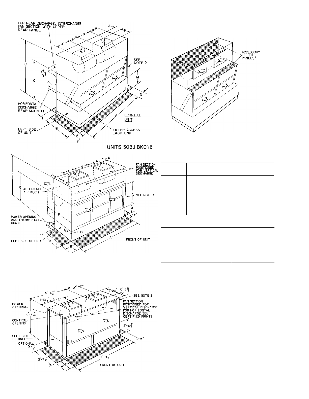
Step 3 — Provide Unit Support
Refer to Fig. 1 — Unit Dimensions, and Table 1 —
Unit Physical Data for unit size and weight. Floor
unit loading should be adequate to support unit.
Step 4 — Rig and Place Unit With Accessories
Collect all unit parts together and move them to
actual installation site. Provide space around unit
for service, filter access and overhead clearance as
indicated in Fig. 1.
Move and store unit in upright position. Do not
remove shipping package or skids until unit is at
final position. Follow rigging label instructions
to prevent cabinet damage during unit positioning.
DO NOT USE CHAINS. Raise base skid on blocks
and remove bolts. Unbolt fan section from skid
(028 and 034 units only).
If any 39E accessories (eg. filters) are to be used
on 50BJ,BK044-064 units, refer to latest 39E
Installation Instructions. The 50BJ,BK044-064
units do not contain installed filters or racks. Bolts
to secure filter rack are shipped secured to base unit
compressor basepan.
Units as shipped are adequately dampened
against vibration. If additional dampening is de
sired, place sponge rubber, rubber mat or fiberglass
roof insulation between floor and base of unit or
install vibration isolators.
Step 5 — Position Fan Section As Desired
UNIT SIZES 50BJ,BK0I6 and 024 are shipped for
vertical discharge. To set up these units for topmounted horizontal discharge, accessory filler
panels must be field installed (see Fig. 1).
To set up unit sizes 50BJ,BK016 and 024 for
back-mounted horizontal discharge (Fig. 1), pro
ceed as follows:
1. Remove:
a. rear fan-section panel.
b. upper rear coil-section panel.
c. flexible conduit and wires from motor.
d. corner bolts holding fan section to coil section.
2. Remove fan section and rotate it 180° lengthwise
so that motor is on left side of unit.
3. Place fan section on rear of coil section and
refasten.
4. Replace motor wire and conduit.
5. Adjust the following items per Installation Step 8:
a. Shaft alignment.
b. Fan wheel position.
c. Pulleys.
d. Fan belt.
6. Replace panels as follows:
a. Upper rear coil-section panel on top of coil
section and fasten.
b. Rear fan-section panel on top of fan section
and fasten.
UNIT SIZES 50BJ,BK028 AND 034 are shipped in
sections as noted previously. They can be field
assembled for either vertical or horizontal discharge.
NOTE: Fan section panels may be removed for
easier lifting and to facilitate motor installation.
To set up sizes 50BJ,BK028 and 034 units for
horizontal discharge (Fig. 2), proceed as follows:
1. Remove:
a. Upper rear and end panels of coil section.
b. End panels on fan section.
c. Fasteners holding lower rear edge of fan panel.
2. Eift and position fan section on rear of coil
section (Fig. 2). Secure with fasteners provided.
3. Install the following per Installation Step 6:
a. Motor mounting frame angles.
b. Motor on plate assembly.
e. Motor-plate assembly on frame angles.
d. Balance of drive package components.
4. Adjust the following per Installation Step 8:
a. Shaft alignment.
b. Fan wheel position.
c. Pulleys.
d. Fan belts.
5. Replace panels as follows:
a. Rear coil section panel on top of coil section.
Rear holes will overlap fan section top panel.
Fasten using hole vacated in step Ic (see
Fig. 2).
b. All end panels.
Page 3
-> Table 1 — Unit P
MODEL50
OPERATING WEIGHT (lbs) (Note 1)
BJ
016
1420
OPERATING CHARGE (lbs)
System 1
24
System 2
COMPRESSOR — TYPE 06
System 1
System 2
No. of Unloading Cylinders
No. of Capacity Steps
HPS Setting (psig)
LPS Setting (psig)
DC337 1 DC537
4
3
280 j 376
27
CONDENSER (BJ Only)
No. ...Type
Max. Working Pressure (psig)
1 SC
550
Connection Size - (in.)
Water Inlet
Water Outlet
(1)2 FPT
(1)2 FPT
CONDENSER (BKOnly)
Connection Size - (in.)
Liquid
Discharge
% ODM (2)5/8 ODM
1У8 ODM
CONDENSATE CONNECTION
Condensate Drain
1 FPT 1 FPT
INDOOR FAN (Note 3)
Number
Size (in.)
Nominal Cfm
Maximum Allowable Rpm
No of Belts...Fan Pulley PD (in.) (Note 4)
Fan Shaft Diameter - (in.)
2 2
15x11 15x11
6,000 8,000
1200 1200
1 90 2 90
1^^
Horsepower
Standard...Frame Size
Motor Pulley A Diameter
Motor Pulley B Diameter
Motor Efficiency (%)
Motor Shaft Diameter (in.)
3 182T
4 5-5 5
—
79
1У8
Center To Center (standard and horizontal) 8 8-11 1
Center To Center (alternate top discharge)
— —
Fan Speed Range (Rpm)
Pulley A
875-1069
Pulley B
Alternate...Frame Size
Motor Pulley A Diameter
Motor Pulley B Diameter
Fan Speed Range (Rpm)
Pulley A
Pulley B
5 184T
—
— —
___
—
INDOOR COIL
No of Rows... Fins/in. 3 110
Total Face Area (sq ft)
16 3
RETURN AIR FILTERS
No. . .Size (in.)
3 16x25x2
3 20x25x2
Cfm — Cubic Feet Per Minute ODM — Outside Diameter Male
FPT — Female Pipe Thread ODS — Outside Diameter Solder
Hp — Horsepower PD — Pitch Diameter
MPT — Male Pipe Thread PDR — Pitch Diameter Range
BK BJ BK
024
1225 1900 1470
15 17
17
DC724 1 DC824
DA724 1 DA824
4
6
280 1 376
27
2 SC
150 (Note 2)
(1)2 5 FPT
(1)2 5 FPT
(2)У8 ODM
Р/б V'Ae
5 .184T
4 6-5 6
84 84
1У8 1%
8 8-11 1 29 8-33 3
894-1089 925
—
7 5.213T 10 215T
— —
— —
4 110
17 4
3. 16x25x2
3 20x25x2
Rpm — Revolutions Per Minute NO
SC — Shell and Coil
TT — Tube-in-Tube
BJ
028
2500
24
17
DC337 j DC
DA724 j da
280 1 3
2 SC
15 + 2 FPT
15 + 2 FPT
(2)% ODM
1У8 ODM
1У4 MPT
18x18
10,000
1100
2 124
7 5 213T
1073
4 90
21 9
6. 25x20x2
2 16x20x2
4
6
27
550
5 6
6 5
__
23
A
2
1 1
1
2.
t
Page 4
- Unit Physical Data
BJ
034
2610 2440
Refrigerant 22
24 1 15
24 15
c
lerviceable Hermetic, 1750 Rpn
DC337 1 DC537
DA337
4
e
280 376
27
2
550
(2)2
(2)2 FPT
Size (in ) Type
(2) Ув ODM
(2) 1 Ув ODM
Size (in
1У4
028
4
27
2
SC
550
5 + 2 FPT
5 + 2 FPT
)Ув
ODM
Ув
ODM
P/4
MPT
BK
2335
15
12
DC537
DA824
376
Adjustable, Belt-Driven Centrifugal; 1750 Rpm Motor
2 2
18x18 18x18
10,000 12,000
1100 1100
2 12 4 2 11 0
I'Me VVu
SC
FPT
) Type
MPT
BK
DA537
BJ
3660
30
30
1
E2150
EA150
2
(2) 2Ув
(1)ЗУв
(2) Ув
(2) 1 Ув
1У2
BK BJ
044
3155
18
18 35
Е2250
ЕА250
2
4
395
27
TT 2
400
ODS
ODS (1)ЗУв ODS
ODS
ODS
FPT
2888 3298 4030
45 18
E7265
EA150 ЕА250
(2) 2Ув
(2) Ув
(2)1з/в
1У2 FPT
054
395
400
2
20 X 10
16,000
1200
2 187
1'Me
20 X 18
20,000
1200
2 18 7
^"Ae
BK
18
Е7265
1
\ 4
27
TT 2
ODS
ODS
ODS (2) 1Ув
2
^ BJ
_______
40
40
E7175
EF175 EF275
(2) 2Ув
(1)ЗУв
(2) Ув
1У2 FPT
BK
064
3305
18
18
Е7275
e
395
27
TT
400
ODS
ODS
ODS
ODS
2
20 X 18
24,000
1200
2 18 7
1"4б
'5 213T 7 5 213T
5 6 5 6
6 5 6 5
84 84
1 % 1 %
>9 8-33 3 29 8-33 3
925
1073
10 215T
Copper Tubes, Aluminum Plate Fins
4 90 4 90
21 9 26 2
Factory Supplied — Throwaway
25x20x2 6 25x20x2
16x20x2 2 16x20x2
NOTES
1 Operating charge for 50BK units does not include charge for
matching air-cooled condenser or refrigerant connecting
piping All 50BK units are shipped with a holding charge
Operating charge values are approximate
2 Condenser working pressure is 550 psig if factory installed,
dresser adapters are removed and field-fabricated manifold is
installed
925
1073
10 215T
15 254T
9 0
10 3
85
1%
17 9-21 1
18 4-22 0
840
961
20 264T
10 9
11 8
1023
1107
3 15
37 5
None
(See Note 5)
20 264T
9 8
10 9
87
1%
17 9-21 1
18.4-22.0
915
1023
25 284T
10 9
11 8
1032
1117
4 15 4 15
37 5
None None
(See Note 5) (See Note 5)
Motors and drives other than those furnished with units
016-034 must be purchased locally Installation may require
field modification
Fan motor pulleys on 50BJ,BK028,034,044,054,064 are fixed
pitch type The smaller of the 2 pulleys is factory installed
Refer to 39E Series literature (size 39E32) for accessory
information
25 284T
9 8
10 9
89
1%
17 0-20 4
17 6-21 5
922
1032
30 286T
10 9
11 8
1029
1114
37 5
Page 5
OPTIONAL TOP HORIZONTAL DISCHARGE
*For optional top-mounted horizontal discharge, use
accessory filler panel package as shown
DIMENSIONS (ft-in.)
UNIT
50BJ.BK
A 6-8 7- 9V4
B 2-4 2-11V4
C
D
E
F
G
H 1- 4V4
016
6-10'/2
2-0
3-0
3%
11- 2%
024
028 j 034
8- OVe
2-0
3-0
1- 8Vb
1- 8%
1- 7Vs
NOTES:
1 Certified dimension drawings available on request
2 Water and refrigerant connections located on right side of unit.
UNITS 50BJ,BK028 AND 034
UNITS 50BJ,BK004, 054, AND 064
Fig. 1 — Unit Dimensions
UNIT 1
50BJ.BK 1
J
K 2-0
L
p 4- 4% 5-41/8
Q
016 1 024 028 1 034
0-1%
M 1 1-8 2-1 Vs
IM j
—
—
4-11'/2
ACCESS AREA
AIRFLOW
0-2%
1-4
3-2V4
7-41/4
5-71/4
0
NOTES:
1 Certified dimension drawings available on request
2 Water and refrigerant connections for unit sizes
50BJ,BK044 thru 064 are located on right side of
unit See Fig 12 for connection details
3 Filters are not supplied with base unit. All models
are directly compatible with 39E (size 32) air
handling unit components Refer to 39E literature
for physical data for accessories
ve
2.
3.
4.
5.
6.
4
Page 6
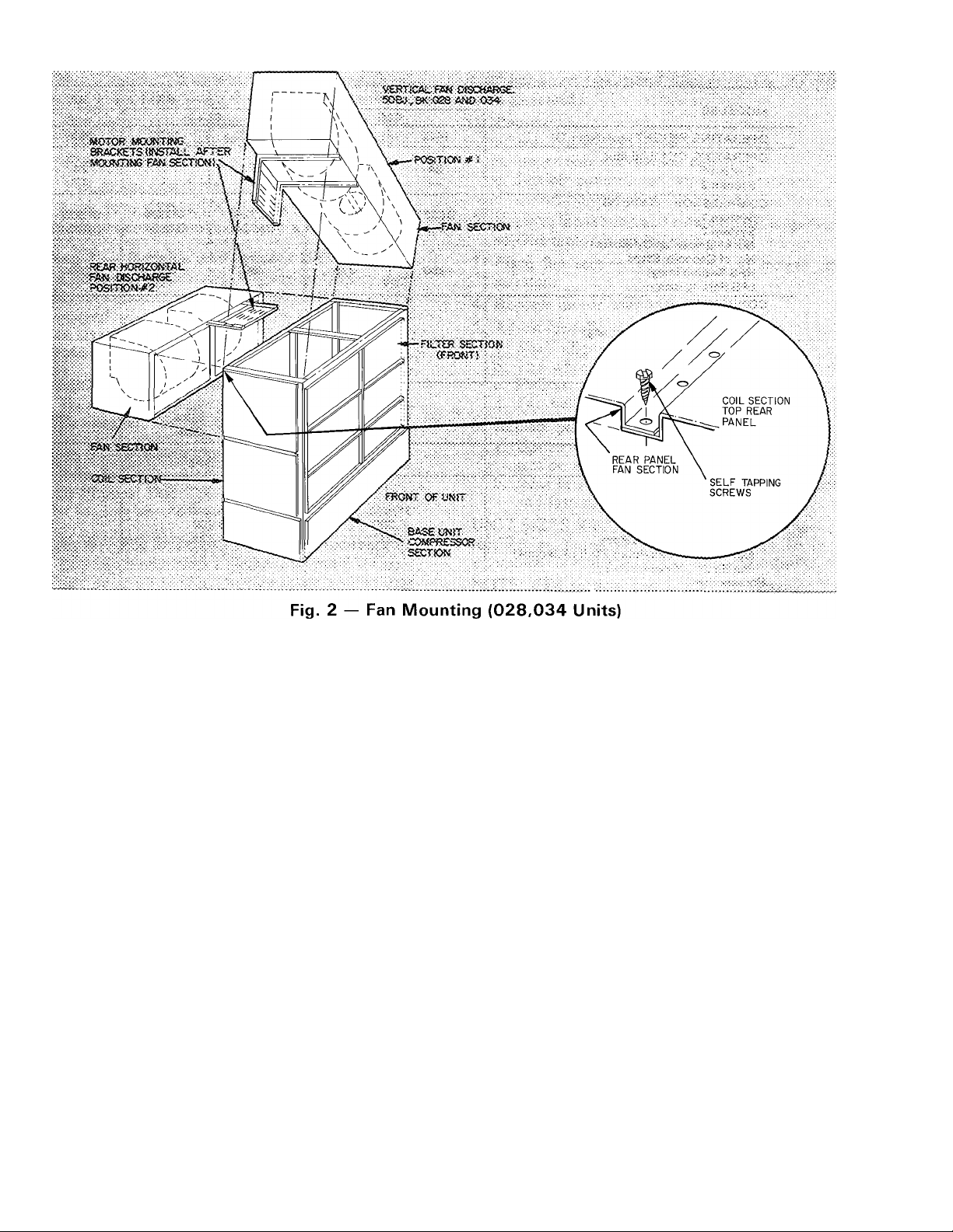
To set up sizes 50BJ,BK028 and 034 units for
vertical discharge (Fig. 2):
1. Remove:
a. Front, rear and end panels of fan section.
b. Upper-rear and end panels of coil section.
c. Filters from coil section.
d. Fasteners holding filter frame top. Push out
frame away from coil section frame.
2. Lift up and position fan section on coil section
(Fig. 2).
3. Fasten fan-section frame to coil-section frame
with fasteners provided; then reposition and
refasten the filter frame moved in step Id.
4. Install the following per Installation Step 6:
a. Motor mounting frame angles.
b. Motor on motor-plate assembly.
c. Motor-plate assembly on frame angles.
d. Balance of drive package components.
5. Adjust the following per Installation Step 8:
a. Fan wheel alignment.
b. Shaft alignment.
c. Pulleys.
d. Fan belts.
6. Replace panels as follows:
a. Rear coil-section panels, front and rear fan-
section panels.
b. All end panels.
Unit sizes 50BJ,BK044,054 and 064 are shipped
with vertical discharge as standard. Other fan posi
tions are available as a factory-installed option.
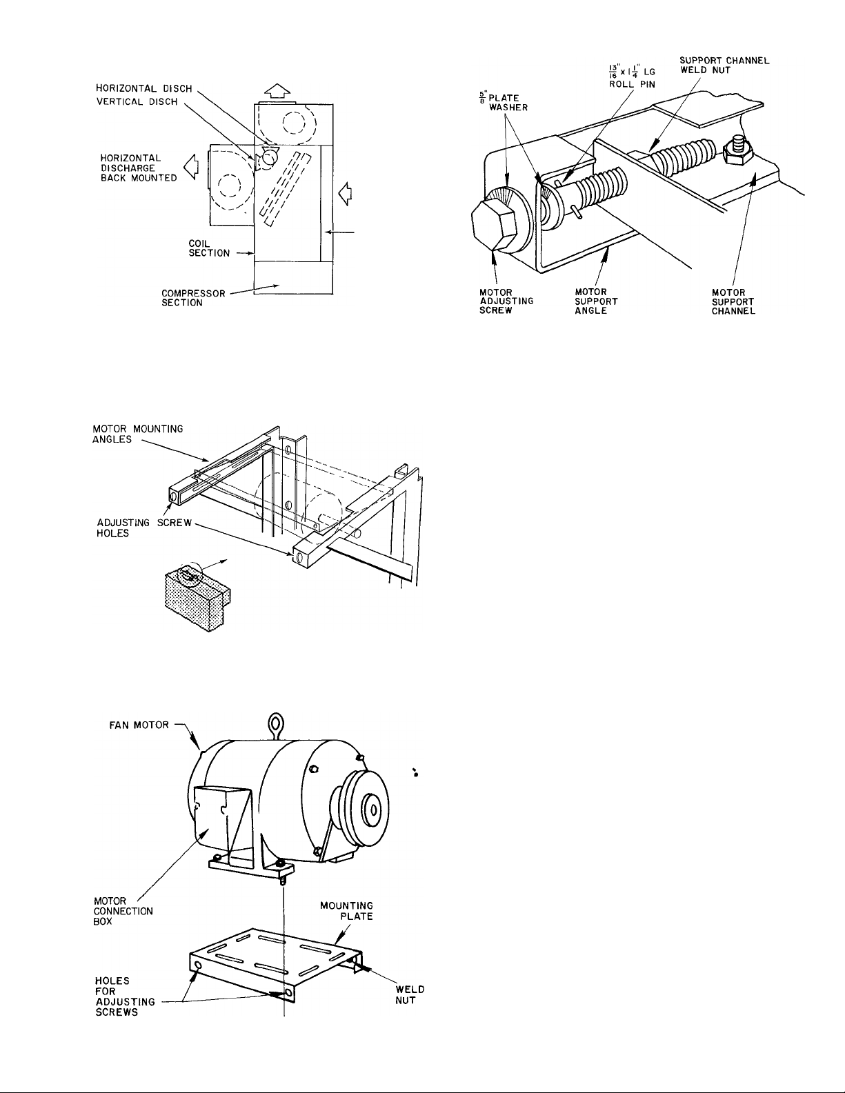
Step 6 — Install Fan Motor. Unit 50BJ,BK028
and 034 only. (All other units have factory-installed
motors.) Install items after fan section frame has
been placed in position on coil section.
NOTE: Place plywood over evaporator coil to
prevent damage while installing motor and mounts.
To install motor:
1. Fasten motor mounting angle bracket to fan
section. Use Fig. 2 or 3 for position reference
and Fig. 4 for assembly guidance. Be sure that
lips of angle brackets are around fan section
frame and that slots for motor mounting plate
face each other.
2. Position motor on motor plate (Fig. 5) and
fasten with fasteners provided.
3. Lift motor-plate assembly and slide into motor
mounting angles as shown in Fig. 4. Plate fits in
angle slots. On vertical mounts, the motor
mounting assembly can be lowered to bottom of
motor support channels.
4. Assemble and install motor adjusting screws as
shown in Fig. 6. Drive roll pins into screws to
prevent the screws from backing out during
motor position adjustment.
t
Page 7
VERTICAL DISCH
FAN MOTOR POSITION
NOTE.
Motor pulley on left side of unit — vertical discharge
Motor pulley on right side of unit — horizontal discharge
TOP MOUNTED
Fig. 3 — Fan and Motor Arrangements
50BJ.BK028.034
AIRFLOW
FRONT
■ FILTER RACK
Fig. 6 — Assembled Fan Motor
Adjusting Screw
5. Adjust motor position. Fasten motor mounting
plate to mounting angles.
Step 7 — Route Fan Motor Wire (Unit 50BJ,BK
028 and 034 only)
Fan motor must be field wired. Proper wire rout
ing is essential to the operation of these units.
Follow wire routing instructions carefully.
Fig. 4 — 50BJ,BK028 and 034 Horizontal
Fan Motor Mounting Angles
Fig. 5 — 50BJ,BK028 and 034 Motor
Mounting
CAUTION: Ttira t^ïricaï power to base
before cot-ttiag mriog to few matm.
CHECK EQUIPMENT — Refer to Fig. 7 and 8 for
location of base unit components. Fan motor wiring
is shipped coiled on top of evaporator coil. Wire tie
locations are shown in Fig. 7, 8 and 9.
ROUTE WIRING
CAUTiON: with aafScaeiit
to pertmi motor a<3|ssii»esi£. not
be pfecbed^ toecli zm moviiig parts or sharp
odgra.
VERTICAL DISCHARGE (Fig. 2. Position #1)
Run wiring thru wire tie# 1 (Fig. 9) on motor mount
ing bracket to the fan motor and secure. Route
wiring from wire tie around motor side of mounting
bracket to fan motor connection box on top of
motor (Fig. 5). Cut off and discard excess wire.
Refer to base unit label diagram for wiring connec
tion details.
HORIZONTAL DISCHARGE (Fig. 2, Position
#2) — Run wiring thru wire ties #2 and 3 (Fig. 9) to
the fan motor and secure. Run wiring to connection
box at back of motor (Fig. 5). Cut off and discard
excess wire. Refer to unit label diagram for wiring
connection details.
Step 8 — Align Fan Shaft and Wheel
HORIZONTAL WHEEL CENTERING — All
wheels must be horizontally centered between the
inside edges of their fan scroll venturis (Fig. 10).
Page 8

Fig. 7 — Typical 50BJ,BK028,034 Unit — Vertical Discharge
fA« MOTOR
Piti SECTiON
£V^«=<»ArOi? CCiL
Fig. 8 — Typical 50BJ,BK028,034 Unit — Horizontal Discharge
Page 9

Table 2 — Setscrew Torque Requirements
BOLT SIZE
(in.)
%
Vs
A VsfmCAL DfSC^íARS£
1 RECOMMENDED
TORQUE (Ib-ft)
1 15-18
1 22-25
Fig. 9 — Wire Tie Locations
WHEEL
CONCENTRIC ALIGNMENT—Shaft and wheels
must be concentrically centered with the venturi or
air inlet of the fan housing.
7SCROLL
VENTURI
ALL UNIT SIZES — Bearings are bolted to sup
ports. To correct shaft and wheel concentric
misalignment:
1. Loosen bearing support bolts and shim or move
as required.
2. Retighten bearing support bolts,
HORIZONTAL SHAFT ALIGNMENT (All
Units) — If the shaft has moved and all wheels are
off horizontal center, recenter the shaft as follows:
1. Loosen setscrews holding bearing locking collar
at each end of shaft.
DIMENSION "d"
MUST BE EQUAL ALL AROUND
Fig. 10 — Horizontal Wheel Centering
2. Slide shaft and wheel assembly horizontally until
wheels are horizontally centered (Fig. 10).
3. Slide the bearing locking collars against the
bearing race; turn in direction of shaft rotation
until tight.
Adjust as follows:
Units 50BJ,BK0I6 and 024
1. Loosen setscrews holding wheel support to shaft
(Fig. 11).
2. Center the wheel by sliding it horizontally
(Fig. 10).
3. Retighten setscrews.
Units 50BJ,B1C028,034,044,054 and 064
#
1. Loosen fan wheel square head setscrews on each
side of fan support (Fig. 11).
2. Center wheel by sliding it horizontally (Fig. 10).
3. Retighten locking setscrews to torque specified
in Table 2.
4. Retighten locking collar setscrews.
FAN, PULLEY AND BELT ADJUSTMENT —
Refer to the Service section entitled Indoor-Air
Fan Adjustment.
Step 9 — Install Field-Fabricated Ductwork
Connect ducts to unit, using flexible connections
as required. Duct angles are supplied with each
50BJ,BK044,054 and 064 unit. Install duct angles
at duct openings using flexible connections. Connect
supply ducts to flanges. Supply ducts should not be
manifolded together for at least 4 feet.
Attach ductwork to building structure and in
sulate. Add a vapor barrier to prevent sound trans
mission and vapor condensation.
Page 10

Weatherproof external ductwork, joints and
openings with flashing and mastic in accordance
with applicable codes.
Ducts passing thru an unconditioned space must
be insulated and covered with a vapor barrier.
Step 10 — Check Return Air Filters Unit 50BJ.BK (016-034 only)
Be sure that the filters are the correct size; refer to
Table 1. Do not operate the unit without these
filters in place.
Step 11 — Check Compressor Spring Mounts
The compressors are held rigid in shipment by
bolts extending thru a washer, lockwasher and
compressor foot into a weld nut.
Loosen and remove each bolt (4 per compressor)
until compressor floats free on springs. Remove and
discard washer and lockwasher. Take bag provided
with compressor and remove grommet and new
washer. Install grommet and new washer. Replace
and tighten bolts so that there is slight pressure
on grommet. This will steady compressor and pre
vent start and stop rocking.
The compressors have reversible oil pumps that
operate in either direction; therefore the direction
of rotation need not be checked.
Step 12 — Make Condenser Connections
WATER-COOLED (50BJ unit) — Condensers
have water inlet and outlet connections as shown in
Fig. 12. Piping arrangements for city, waste or
recirculating water are shown in Fig. 13 thru 16.
Recirculating systems with low-temperature
water returning to the condenser may require a
water regulating valve. Units used on waste or city
water must have a regulating valve on the inlet of
each condenser and will require field modification
for separate condenser piping. Refer to Fig. 13, 14,
15, 16 and 17 for typical applications and
conversions.
2“FPT WATER
5OBJ0I6
50BK0I6
l" FPT
7/8" ODM HOT
50BK024
HOT GAS \
CONN 1
7"0DS
8 (028) f ^
I^ODS )
°t034) ^
l"-5 —
FLOOR 1
LINE T'
50BJ028
ё'
A
1 i"
♦ 1-4%
2
50BK028 a 034
‘•^Гб'
-Ig ODS
I
8
LIQ LINE
C0NN.(028
034)
HOT GAS
CONN (028
034)
NOTE: RIGHT SIDE VIEW OF UNIT SHOWN
Fig. 12
liEP.T CONDENSATE
DRAIN CONN.
2-|T , '
^ '/* 1-10,4
Water and Refrigerant Connections
50BJ044,054,064
9
3g IDS
WATER
RETURN
I^FPT
CONDENSATE
DRAIN CONN.
^ '4|б|"®2
50BK044,054,064
I ID LIQ
TUBE
(CKTI)
l|"l,D
HOT GAS
TUBE
(CKT I )
f I D HOT GAS
TUBE (CKT 2)
Page 11

CONNECT WATER REGULATING
VALVE TO COMPRESSOR
Fig. 13
50BJ024 City Water Condenser
Piping Conversion
1X1-
i|HXl-RETURN
CONNECT TO»rn
COMPRESSOR y
{X1-—dJo—
HXh
Nominal supply and return lines must be sized to provide required
gallons per minute at condenser All supply piping and valves are
2 in Return piping is 3 in Condensate drain is 1
supplied and installed external trap is required
-Cxi-
^^STRAINER
------
l||-C]— SUPPLY
Distrainer
'/2 in FPT Afield-
Fig. 16 — 50BJ,BK044,045 & 064
Condenser Water Piping
Install a water regulating valve on the inlet of each
condenser with any size unit used on waste or city
water (Fig. 14, 15 and 16).
Connect the regulating valve capillary to a back-
seated liquid service valve. Arrow on valve body
must point in direction of water flow. After con
necting capillary, open regulating valve one turn
from back-seated position. Adjust valve as required
to maintain proper condensing temperature.
Install full size gate valve and strainer in the water
supply line. See maximum working pressures in
Table 3. Valve and strainer must be accessible.
Fig. 14 — 50BJ024 Typical Waste or
City Water Piping
Table 3 — Maximum Water-Side
Working Pressure
UNIT SIZE 50BJ.BK
016 550
024
028,034
044,054,064
*550 psig if factory-installed dresser adapters are removed and
field-fabricated manifold is installed
MAXIMUM WORKING
PRESSURE (psig)
150*
550
400
AIR-COOLED (50BK units) — Install air-cooled
condenser in accordance with the Installation
Instructions shipped with condenser.
Consult Carrier System Design Manual for
standard refrigerant piping techniques. Connection
locations for liquid and hot gas service lines are
shown in Fig. 12. Recommended line sizes are
listed in Table 4.
Condenserless (50BK) units are shipped with a
holding charge. After refrigerant connections are
made, evacuate, leak test and charge the system as
described in the Service section entitled Charging
the System. Refer to Table 1 for approximate unit
charge.
10
Page 12

Table 4 — Recommended Line Sizes (in.)
(50BK Condenserless Models)
UNIT
50BK
HG — Hot Gas Line (OD in ]
L — Liquid Line (OD in )
‘Sweat connections
SYSTEM
016 —
024
028
034
044
054
064
1 & 2 % Vs Yb ys Ye
1 & 2 1 %
1 & 2 % IVs Vb V/a
1 & 2 % lys Vb
1 & 2
1
2 Ys ys
CONN.
SIZES*
L
% ^Ve Ve
% ^Vв Va
ys ^Уe
HG L HG
r/s Yb
LENGTH OF LINE (ft)
20
1'/s ys
1'/s Vb
ys Ya p/s
Yb
1 Vb Va
P/s Vb
P/s Va p/s ys
Vb
40
L
HG L
P/s .
P/s ys
p/s ys'
p/s ys p/s
Vb
p/s ys
p/s ys
60-80
ys
Ps
HG
P/s
P/s
p/s
p/s
p/s
p/s
p/s
Step 13 — Install Unit Drain Line
Install a trapped condensate drain line at unit
drain connection (Fig. 12). The drain requires
standard pipe connected to condensate pan nipple
as shown in Table 5. Figure 18 shows proper
trap design.
Determine design negative static pressure. This
pressure is not the same as fan total pressure,
which includes pressure losses downstream as well
as upstream from the indoor air fan. Always assume
the worst conditions, such as having return air
filters clogged with dirt.
Referring to Fig. 18, Differential 1 must be equal
to or larger than negative static pressure at design
operating conditions. Store enough water in trap to
prevent losing seal (Differential 2). This differential
must be equal to or larger than one-half the maxi
mum negative static pressure. When the fan starts.
Differential 3 is equal to the maximum negative
static pressure.
Table 5 — Condensate Drain Connections (in.)
UNIT SIZE : 016,024
PIPE SIZE ;
1 P/4
028,034
044,054,064
P/2
50BJ.BK044-064 UNITS
Fig. 17 — Refrigerant Systems (016-064)
TRAP CONDITION WHEN FAN STARTS
Fig. 18 — Condensate Drain
II
Page 13

Do not use drain line smaller than size listed in
Table 5. If required, cut hole in panel for drain line.
Piteh drain downward toward an open drain sump.
Provide a trap at least 3 in. high with plugged tee for
cleaning. Fill trap with water to make an air seal.
Observe all sanitary codes.
unbalance in supply voltage is greater than 2%. Use
the following formula to determine the % voltage
unbalance:
max voltage deviation
% Voltage _ jQQ from average voltage
Unbalance ~ average voltage
Step 14 — Make Electrical Connections
GENERAL — Provide an adequate fused dis
connect switch per NEC within sight from the unit.
Provision for locking switch open (OFF) is ad
visable to prevent power from being turned on when
unit is being serviced.
On all units, power may be supplied thru a branch
circuit. Branch circuit protection is provided in these
units by manual reset circuit breakers. Branch
circuit must be in accordance with NEC or local
code, whichever takes precedence. Power supplied
to auxiliary equipment, such as fan motors for air
cooled condenser or for cooling tower, must be
run separately.
^POWER WIRING — Conduit opening for 016-034
units is on back of unit near control box. Conduit
opening for 044-064 units is on top of unit near
control box. On all sizes, field power connections
are made at a terminal block within the control box
(see Fig. 19). Refer to Table 6 for maximum wire
size at terminal block.
50BJ,BKOI6-034
BLU
YEL
BLK
----------------
—7
FIELD
POWER
SUPPLY
FIELD
POWER
SUPPLY
---------------------------------------0L3 0-
------
O L2 O-
-----------
OLI O-
-01
EQUIP. GND.
L3
L2
LI
-------------------
--------------------
50BJ.BK 044-064
—
FIELD WIRING
FACTORY WIRING
TBI
IfTl—1
iV 1 1
EQUIP. GND,
llU
ÜU
rm
ÜU
Fig. 19 — Field Power Wiring Connections
Supply voltage must be in accordance with name
plate voltage. On 3-phase units, voltage between
phases must be balanced within 2% and current
within 10% with compressor running. If supply
voltage is not in accordance with nameplate voltage,
a phase unbalance may occur. Voltage at com
pressor must be within the minimum and maximum
shown in Table 7.
Contact local power company for line voltage
corrections. Never operate a motor where a phase
Example; Supply voltage is 240-3-60.
A B r, AB = 243 volts
BC = 236 volts
AC = 238 volts
Average Voltage =
Average Voltage
243 + 236 + 238
717
= 239 volts
Determine maximum deviation from average
voltage:
(AB) 243 — 239 = 4 volts
(BC) 239 — 236 = 3 volts
(AC) 239 -- 238 = 1 volt
Maximum deviation is then 4 volts. To determine
the % voltage unbalance:
1 Voltage Unbalance = 100 x
4
239
= 1.7%
This amount of phase unbalance is satisfactory
since it is below the maximum allowable of 2%.
IMPORTANT: ff supply voRage phase «abalaace h more than 2%, contaci your local
electric tiiility company immedjaieiy.
^ Compressor operation on improper line voltage
or excessive phase unbalance may be considered
abuse and anv resulting damage may not be covered
by Carrier warranty.
All wiring must be in accordance with local or
NEC regulations.
EIELD CONTROL WIRING — On extended volt
age (208-230-v) units, control transformer is factory
wired for 208-v usage. If unit is to be used on 230-v
system, reconnect primary wiring on transformer as
shown on unit wiring diagram.
When accessory timer control panel is used,
connect panel to factory-supplied control panel
as indicated on unit label diagram.
^WINTER START-UP PACKAGE — On 50BK
044-064 units, an accessory winter start-up package
is available for providing a 3-minute time delay by
shorting out the low-pressure switch on each com
pressor. This enables each compressor to start even
during low ambient conditions.
^HEATING COILS — Accessory heating coils are
available for field installation. Separate installation
instructions are shipped with the accessory (016-034
only). For 50BJ,BK044-064 units, refer to latest
39E (size 32) literature.
12
Page 14

Table 6 — Maximum Wire Size for
Power Terminal Block*
VOLTS/PHASE
208-230/3
460/3
016
2/0
2/0
575/3 2/0 2/0 2/0
024
UNIT 50BJ.BK
028,034
2/0 350
2/0 2/0
054,064t
044t
350
350
350 350
500
350
Table 7 — Unit Electrical Data
VOLTAGE
UNIT
50BJ016
50BJ024
50BJ028
50BJ034
50BJ044
50BJ054
50BJ064
50BK016
50BK024
50BK028
50BK034
50BK044
50BK054
50BK064
FLA — Full Load Amps
Hp — Nominal Horsepower
LRA — Locked Rotor Amps
MCA — Minimum Circuit Amps
MOCP — Maximum Overcurrent Protection Device (amps)
RLA — Rated Load Amps
*Minimum circuit amps (MCA) for wire sizing complies with NEC Section
430-24
fin compliance with NEC requirements for multi motor and combination load
equipment (Ref NEC Articles 430 and 440), the overcurrent protective
device for the unit shall be fuse only
NOTES:
1 Compressor circuit breakers are current sensitive and temperature
compensated to ensure compressor cutoff if current draw becomes
excessive Breakers must be manually reset
VOLTS/PH/HZ
208-230/3/60
460/3/60
575/3/60 518
208-230/3760 n
460/3/60 414 508 160 62
575/3/60
208-230/3/60 187
460/3/60
575/3/60 518
208-230/3/60 187
460/3/60
575/3/60 518
208/230/3/60
460/3/60
575/3/60 518
208/230/3/60
460/3/60
575/3/60 518
208/230/3/60 187
460/3/60 414 508 42 6
575/3/60 518
208-230/3/60 187
460/3/60
575/3/60 518
208-230/3/60
460/3/60
575/3/60 518
208-230/3/60
460/3/60
575/3/60 518
208-230/3/60
460-3-60 414 508 29 0
575/3/60 518
208/230/3/60
460/3/60
575/3/60
208/230/3/60
460/3/60
575/3/60 518
208/230/3/60
460/3/60
575/3/60 518
RANGE
Min Max RLA LRA
187 254 50 0
414
187
518
414 508 22 2
414
187
414 508 26 5 142 26 5
187
414 508 35 8
414
187
414 508 20 0 77
187 254
414 508 29 0
187
187
414 508 35 8
518
187
414
187 254
414 508 56 5
508
632 17 9
254
632
254
632
254
508
632
254
632 22 2
254
632
254
632
254
508 29 0 120
632
254
632
632
254
632
254
632
254
508 48 6
632
632
COMP #1
22 1 86
36 0 137
129
^ 49 3 191 35 7
180 69 13 0
49 3 191
22 2
180
57 9
80 8
30 0
91 5 446 91 5
32 2 164 32 2
64 0 266
23 0 96
45 0
160 62
64 0 266 45 0
23 0 96 17 0 62 T/2
64 0
23 0 96
77 2
30 0
101 5
38 6 164
120 0 506 120 0 506
42 9 176 42 9
*Select wire size per NEC and connect supply wires to factory-
supplied pigtail wire connectors
tMaximum wire size for 50BJ,BK044 units with alternate drive
package is 500 MCM
IMaximum wire size for 50BJ.BK054 units with standard drive
package is 350 MCM
COMP #2
RLA
191
69
50 12 9 50 5
86 16 0 62
86 22 2
69 18 0 69 I'h 8 7
283 57 9 283 15 46 2
98
446
223 26 5 142 20 27 0
164 22 2
253
170 45 0
120 20 0
266
120 29 0 120 I'h
345 77 2 345 15 46 2
173 35 8 173 15 21 0
VO 30 0 120 15 15.4
446 77 2 345 20 59 4
223 37 9 173 20 27 0
253 56 5
—
—
—
36 0 137 5 13 2
160 62 5 6 6 42 6
49 3 191 IVi 22 0
22 2
60 0 283 20 59 4
42 6
— —
—
—
20 0 77 5
16 0 62 5
64 0
23 0 96 I'h 8 7
30 0 120 20 20 0
Discharge gas thermal protection or internal protection with automatic
reset de-energizes the control circuit if extreme compressor motor
temperature should occur from excessive gas temperature or motor
overloading
Low- and high-pressure switches automatically shut off compressor(s)
if refrigerant pressure exceeds switch settings This action protects
against loss of charge
Indoor fan motor circuit breaker protects against motor overload Breaker
requires manual reset
The 50BJ,BK units are ETL listed at 208/230 and 460 v and C S A certi
fied at 575 V
Phase imbalance shall not exceed 2%
Wire sizing amps are a sum of 125% of the FLA for the largest motor plus
100% of FLA for all other motors in the unit
Maximum instantaneous current flow during starting is the sum of the
LRA for last compressor to start plus the FLA for all other compressors in
the unit
LRA
—
_
—
137 T/2 22 0
50 I'h 8 7
86 I'A
142 15 21 0
98 15 15 4
98 20 20 0
446 25 74 8
253 25
164 25
_
—
170
170
77
266 T/2 22 0
253 25 34 0
176 25 25 6
INDOOR
FAN MOTOR
Hp
I'h 11 0 54 8
Th
T/2
25
FLA MCA*
3
3 4 6 32 2
3 3 7 26 2
3 9 2
3 4 6
3
5
9 2
5 6 35 1
11 0 61 0
34 0 131 9
25 6 100 1
3 7 32 5 50
13 2
6 6 51 6
5 6 41 6
22 0 147 4
11 0
8 7 54 7
11 0 76 3
74 8
71 7 110
94 2 125
Ì2Ó0 150
44 2
132 9
49 2
178 5 225
82 7
64 7
222 4
100 3 125
81 5 110
282 7
89 2 150
40 9 60
114 5 150
67 3 70
166 0
60 5
221 9
103 6 125
84.9
265 5 350
127 7
100 3
346 8 450
163 2
124 2
POWER
SUPPLY
MOCPt
50
40
50
45
70
60
175
80
60
100
80
300
350
150
125
70
50
200
70
200
100
80
250
110
175
125
200
150
13
Page 15

START-UP
General — The 50BJ,BK. units are designed for use
in Modu-Vac Variable Air Volume Systems using
Carrier 37A Moduline® and 35B Modubox Air
Terminals. For air terminal installation and adjust
ment, refer to 37 A or 35B literature as required.
CAPACITY CONTROL — The units are equipped
with electrie unloaders on the lead compressor
(Fig. 17) and hot gas bypass on the no. 1 refrigerant
system. (Size 016 units have only one refrigerant
system.)
Unit capacity is monitored and controlled by a
Honeywell W7100 microprocessor (Fig. 20). This
controller provides the number of capacity control
steps as shown in Table 8.
Table 8 — Capacity Control Steps
Fig. 21 — Accessory Timer Control Panel
UNITS
50BJ.BK I (No. Steps)
016
024,028,034
044 4
054,064
I CAPACITY CONTROL
I 3
6
6
Fig. 20 — Honeywell Microprocessor
TIMER CONTROL — Carrier strongly recom
mends use of an accessory timer control panel with
the 50BJ,BK units. Installation and adjustment of
this device (Fig. 21) is covered in separate Installa
tion, Start-Up and Service Instructions included in
the accessory package.
If accessory timer is not used, install field-installed
manual switch between TB3 terminals [~T~| and
in the variable volume eontrol box for the 016-034
units. Switeh is factory-installed on the 044-064
units.
MOISTURE INDICATORS are located ahead of
thermal expansion valves. They must be full of
liquid to properly indicate moisture content.
Operate system for 30 minutes before determining
moisture content.
SERVICE VALVES (50BK) — Valves use teflon
seat washers to ensure position seal with minimum
stem torque (10 Ib-ft max). Do not overtighten valve
stem. Use wet rag on valve when soldering. If refrig
erant has been lost, midseat valve. Always replace
stem cap.
Prior to Unit Start
1. Clean and inspect the unit.
2. Open (backseat) compressor service valves and
liquid line shutoff valves. Replace and tighten
valve caps to prevent leakage.
3. On 50BK (air-cooled condenser) units, turn on
indoor fan motor circuit breaker. Check that
compressor crankease heaters are energized and
crankcase oil level is half full.
4. Leave crankcase heaters energized for 24 hours
to ensure safe oil/ refrigerant mixture in crank
cases for unit start-up.
Control Sequence Checkout
1. Perform all applicable steps described above
under Prior to Unit Start.
2. Turn on unit main power supply.
^3. Set the control band knob on microprocessor
(Fig. 20) at 2.
4. Turn on indoor fan motor circuit breaker.
5. If unit is equipped with accessory timer control
panel and 7-day clock is not calling for cooling,
turn on unit by overriding clock with manual
bypass switch (see Start-Up General section
entitled, TIMER CONTROL).
6. Close compressor circuit breakers.
7. Check for cooling by turning microprocessor
SETPOINT knob to 40 F. Light-emitting diodes
14
Page 16

(LEDs) should glow as corresponding cooling
stages come on. In addition, indicating lights on
cover of aecessory timer eontrol panel should
light.
^ NOTE: Depending on job eonditions and dif
ferential between setpoint and discharge tem
peratures, minimum time for all stages to eome
on is 22 minutes.
8. Turn mieroprocessor SETPOINT knob to 90 F.
The LEDs on mieroproeessor and indieating
lights on aceessory timer control panel should
go off as corresponding cooling stages drop out.
Ambient temperature must be less than 90 F for
this test.
9. When checkout and unit operation are satis
factory, turn off manual bypass switch (step 5),
position microprocessor SETPOINT knob at
desired temperature (approximately 55 F) and
replace all unit panels.
SERVICE
WARNING; Lock open and tag unit disconnect
before servicing equipment.
CAUTION: Before serv'icing fan compartment.
L Sharp edge.s of evaporator coil fms are ex
posed. To prevent arm inj ury., cover top edge
of evaporator with strip of cardboard or a
few layers of heavy tape.
2. To avoid coil damage, cover coil face with a
piece of plywood or other suitable rigid sheet
material. If any coil fms are mashed or bent,
straighten with a coil fin comb. Check for
refrigerant leaks.
Fan Rotation — Correct fan rotation in respect to
fan outlet is shown in Fig. 22. To check for proper
fan rotation, remove service access panels and jog
fan motor switch. If fan rotation is incorrect, it must
be reversed.
1. Pulleys and fan belts should be aligned and
adjusted as shown in Fig. 23-25.
2. Tighten motor holddown bolts.
3. Replace service access panels.
Indoor-Air Fan Adjustment — Fan motor pulley
is factory set for speed shown in Table 1. Unit sizes
028-064 have fixed pulleys. A second pulley is
shipped with drive package.
Increasing fan speed increases load on motor;
Do not exceed maximtim allowable fan speed
(Table I) or motor fuB load amps shown on
motor nameplate and in Table 7.
TO CHANGE FAN SPEED
1. Shut off power supply.
2. Loosen fan belt by loosening fan motor on
mounting bracket. Do not loosen mounting
bracket from unit.
3. Loosen movable pulley flange setscrew (016,024).
See Fig. 25.
4. Select motor pulley diameter. See Table 1.
5. To increase fan speed, screw movable flange
towards fixed flange; to decrease speed, screw
movable flange away from fixed flange. Use
values shown in Table 1 (016,024).
6. Set movable flange setscrew at nearest pulley
hub flat and tighten (016,024).
7. Check pulley alignment and adjust belt tension
as described below.
8. Check fan operation. Repeat above procedure
as required.
V-BELT INSTALLATION AND TENSIONING
(See Fig. 23, 24, 25 and 26) — Use the following
steps when installing drive belts:
CORRECT
ALIGNMENT
OFF SET
(INCORRECT)
PIGEON TOED
(INCORRECT)
n
ANGLE
(INCORRECT)
Fig. 22 — Fan Rotation
To reverse the direction of rotation of a 3-phase
fan motor reverse any 2 of the power leads. Refer to
the connection diagram on the inside of motor
terminal box cover for proper reversing procedure
of single-phase motor.
Fig. 23 — Fan Belt Alignment
Step 1 — Sheave Conditions — Check condition of
all new and old sheaves. Sheave must have smooth
finish and no sharp edges or burrs. Check for groove
uniformity. Excessively worn sheaves or improperly
machined grooves can lead to early belt failure.
Non-uniformity of grooves will create an unequal
load distribution in matched set of belts.
Step 2 — Mounting Sheaves — Mount sheaves as
close to bearing as possible. Excessive overlap may
cause bearing failure.
15
Page 17

Step 3 — Matched Set of Belts — Always use
matched set of belts. NEVER mix new and used
belts andjor mix belts from different manufacturers.
Step 4 — Belt Installation:
a. Move pulleys together to facilitate belt installa
tion. NEVER pry or roll belt on to pulleys as this
may cause serious damage to belts.
b. Work belts around pulleys by hand. All belts
should be slack on same side of drive. Mixing
slack and tight sides together may result in
.serious damage to belts when drive is tensioned.
THIS OR THIS NEVER THIS
Fig. 24 — Fan Belt Adjustment
c. Move pulleys apart until belts are snug. Make
preliminary check of sheave and shaft alignment.
Operate drive at no load for several minutes to
seat belts and then check belt tension. Excessively
high or low tensions adversely affect the life and
operation of V-belts.
d. Check sheave and shaft alignment after belt
tension is applied.
PULLEY ALIGNMENT — Shut off unit power
Make sure motor and fan shafts are parallel.
Align shafts by loosening motor on mounting
bracket if required. Then loosen fan pulley set
screws, slide pulley along fan shaft and align with
straightedge as shown in Fig. 25.
MOVABLE Flanges
STRAIGHT EDGE MUSt/
SE PARALLEL
WITH BELT /
A
/ ■
\ SETSCREWS
/
A l/
PULLEYS
: SETSCREWS--
SINGLE-GROOVE T-WO-GRC'O'VE
MOTOR a FAN SHAFTS
' ^ MUST BE PARALLEL
nXED FLANGES
Fig. 25 — Indoor Air Fan Pulley
Adjustment and Alignment
TENSIONING (See Fig. 26) — Use the following
steps when adjusting belt tension:
Step 1 — Measure belt span in inches.
Step 2 — Use spring scale at center of span to deflect
belt 1/64 inch for every inch of span length. Record
scale reading.
Example: For span of 10 inches — deflection will be
10 5 . .
tt or inch.
64 32
Step 3 — Spring scale reading should be in range of
12 to 18 pounds. Maximum tension for a new belt
is 18 pounds.
Step 4 — Adjust tension to maximum after 15
minutes. Check belt tension after 2 to 4 hours of
operation.
Step 5 — After 24 to 48 hours of operation, check
drive to see if normal tension is obtained. Exces
sively high or low tension will adversely affect life
and operation of V-belt.
Lubrication — Shut off power Protect
coil from damage.
Fan motor bearings are factory lubricated and
will need no lubrication for the first 5 years of
operation (3 years with continuous service or ex
cessively dirty conditions).
Inspect bearings and relubricate or replace as
required. Follow manufacturer’s instructions for
lubrication of special field-supplied motors.
Fan shaft bearings on 50BJ,BK016 and 024 units
are lubricated for the life of the bearings. Bearings
for 50BJ,BK028 thru 064 units have grease fittings.
On 50BJ,BK044-064 units the fan shaft universal
joint requires the same lubrication as the bearings.
Lubricate annually with a good grade of mixed base
grease or lithium base grease with rust inhibitor.
Add grease until air bubbles form under the seal.
Do not overgrease.
Return-Air Filters — Inspect filters twice monthly
and replaee as often as required by operating condi
tions. Filter type and size is given in Table 1.
If field-supplied, cleanable filters are used, flush
them with hot water or steam, or soak them in a
mild solution of soap or detergent and water. Refer
to filter manufacturer’s instructions as applicable.
Never operate the unit without return-air filters
in place.
Condensate Drains — Clean drain line and unit
drain pan at start of each cooling season. Check
flow by pouring water into drain. Be sure trap is
filled to maintain air seal (Fig. 18).
16
Page 18

Evaporator Coil — Protect coil when working
inside unit. (See screened CAUTION note, page 15.)
Remove dirt and debris from evaporator coil as
required. Clean with a stiff brush, vacuum cleaner
or compressed air. Straighten mashed or bent coil
fins with a fin comb of the correct spacing. Table 1
lists the fins per inch for each coil.
Water-Cooled Condenser(s) may require clean
ing of scale (water deposits). Contact local water
treatment company for best results.
Air-Cooled Condensers — Periodically inspect
and clean depending on operating conditions.
Follow the service instructions provided with the
air-cooled condenser used.
Sight Glasses are provided at the inlet of each
expansion valve. Units may be field charged by
using the sight glass (see Charging the System).
'Charging the System
UNITS WITH WATER-COOLED CONDENSER
(50BJ) — Units are shipped with a full operating
charge of refrigerant. If recharging is necessary
(complete charge lost) weigh in amount of refrig
erant indicated on unit nameplate and Table 1.
If unit has a partial charge, unit may be charged
with sight glass using standard charging techniques.
See Carrier Standard Service Techniques Manual
entitled Chapter 1, Refrigerants for applicable
procedures.
Adjust the water regulating valve to proper
saturated condensing temperature (168 to 226 psig).
UNITS WITH AIR-COOLED CONDENSER
(50BK) — Units are shipped with a holding charge
only. To charge:
1. Open suction and discharge line service valves.
2. Blow holding charge, evacuate and leaktest
system.
3. Add sufficient refrigerant vapor to permit con
tinuous operation after starting unit.
4. Start unit per Start-Up Section; then, using
standard charging techniques, add refrigerant as
required to maintain normal operating
conditions.
Use charging chart supplied with condenser. If
information is not available, block off enough of
condenser coil to maintain 220 psig discharge
pressure and charge to a clear sight glass.
Indoor-Air Fan Motor Removal
Sim oif artd lockout ouit power swply.
A CAUTION
Biotor î3ao«îî£&, place a pjece of i^wooá over
ALL 50BJ,BK UNITS — Remove motor as follows:
1. Remove unit access panel and cover of motor
junction box.
2. Disconnect motor wires and remove conduit
connection.
3. Remove motor bolts and slide motor over so
that fan belt can be removed.
4. Disconnect motor ground wire (if present) and
remove motor.
TO REINSTALL MOTORS — Reverse the above
procedures. Align pulleys and adjust belt tension as
described in the section, Indoor-Air Ean
Adjustment.
Pressure Relief Devices — The 50BK (condenser
less) and 50BJ,BK044-064 units are equipped with
a fusible-plug type safety relief device on the com
pressor. The relief setting is 197 or 203 E on all units.
All 50BJ (water-cooled) units have a frangible
disc on each condenser. Disc setting is 385 ± 5% psig.
^Crankcase Heaters are supplied on all 50BK
(condenserless) units and on 50BJ044-064 watercooled units.
The heater reduces the possibility of liquid refrig
erant from accumulating in the compressor crank
case during extended shutdown periods. Heater is
automatically energized whenever unit main power
is on and compressor is stopped. Heater is de
energized when compressor starts.
Do not shut off unit main power supply for an
extended period except for servicing unit. After an
extended shutdown period, turn power supply on at
least 24 hours prior to starting compressor.
If 50BJ units are installed in unheated rooms,
they should be equipped with crankcase heaters. All
units equipped with crankcase heaters require 24
hours warm up time.
High-and Low-Pressure Switches — The high-
pressure switch is located in the electrical panel.
The low-pressure switch is located on top of
compressor.
Time Guard® Control Circuit provides auto
matic reset protection (except circuit breaker),
time delay in starting and controlled cycling. If
compressor shuts down for any reason, the control
circuit prevents restart for time periods as follows:
UNIT
50BJ.BK
016 1 5
024,028,
034
044,054
064 1 1 and 2 64
CIRCUIT
NO.
1 64
1 2
1 2
A
Full Cycle
(minutes)
5
5
B
Delayed Start
(seconds)
15
19
15
15
19
Column B shows time delay between compressor
starts under normal thermostat cycling.
17
Page 19

CONTROL SEQUENCE
All 50BJ,BK Units — The indoor fan circuit
breaker (IFCB) must be closed for the control
circuit to be energized. When breaker is closed, the
SYSTEM light will be on.
The 044-064 units are equipped with a switch
labeled STANDBY. When switch is closed, the
indoor fan contactor (IFC) is energized and the
indoor fan will start and run continuously. A light
labeled FAN will come on. To use accessory timer
control, switch must be put in STANDBY position.
All units are equipped with the improved Honey
well W7100 discharge air controller. Controller has
3 control knobs: set point, reset and control band.
Controller regulates the leaving air temperature to
the set point. A setting below 50 F may decrease
unit efficiency due to use of hot gas bypass at light
loads. The reset knob adjusts reset control range
from 5 F to 20 F. The reset feature requires fieldsupplied components and wiring. The control band
knob adjusts controller for the required number of
stages. The control band should be set at 6 F for the
016-034, 054 and 064 units, and 8 F for the 044 units.
Increasing control band setting above these recom
mended settings will decrease compressor cycling
and increase leaving air temperature variations.
Decreasing setting will not reduce discharge air
temperature variations but will increase compressor
cycling.
The controller is also factory equipped with 2
fixed resistors. One resistor corrects for the number
of steps. This is done by placing a 1/4-watt, 5%-
8
m
on micro-resistor across terminals m and
processor. A 3-stage, 300-ohm resistor is used on the
016 unit. A 4-stage, 400-ohm resistor is used on 044
units and a 600-ohm resistor is used on 024-034,
054 and 064 units. A second 510-ohm resistor is
connected between terminals 0 and [V] to indi
cate unit does nt have an economizer. These units do
not have a factory-supplied eeonomizer. If a fieldsupplied economizer is added, remove the 510-ohm
resistor. Consult Carrier Corporation for more
details.
If the discharge air deviates 1°F above or below
the control band while unit is running, a cooling
capacity stage will either be added or removed
according to the loading sequence table found on
page 18. Additional capacity steps will be turned on
or off until discharge air temperature is within
control band or is charging at a rate that will allow
it to be within control band within 10 minutes. The
controller also has a fixed guaranteed minimum
on and off time of 4 minutes to prevent compressor
cycling.
These units are equipped with a Time Guard®
circuit. This circuit prevents compressor no. 1 from
restarting until 4 minutes, 45 seconds have elapsed
from last shutdown. Compressor no. 2 will not
restart until 6 minutes, 10 seconds have elapsed.
Each compressor is equipped with a high-pressure
switch (HPS), discharge gas thermostat (DGT) or
internal protection (IP) and low-pressure switch
(EPS). If any of these “trip”, the compressor will
shut down. If, after 4 minutes, 45 seconds for com
pressor no. 1 and 6 minutes, 10 seconds for compres
sor no. 2, the switch resets, compressor no. 1 will
restart within 15 seconds and compressor no. 2
within 19 seconds.
The 50BK condenserless units are equipped with
a liquid line solenoid (ELS). When a stage calls for
compressor shutdown, the liquid line solenoid will
close first. The compressor will continue to run until
the low-pressure switch opens.
Loading Sequence
MODEL
50BJ.BK
016 33%
024 17%
028
034 17%
044 25% 50%
054 19% 38%
064 17% 34% 50% 67% 84%
1 2 3 4
67% 100%
34%
17% 34% 50% 67%
34%
STAGE
50% 67% 84%
50% 67% 84%
75%
57%
— —
100%
63% 84%
84%
-
-----
5
6
—
100%
100%
100%
—
100%
100%
18
Page 20

For replacement items use Carrier Specified Parts
Manufacturer reserves the right to discontinue, or change at any time, specifications or designs without notice and without incurring obligations
Book 1
Tab
2a
Form 50BJ,BK-4SI Supersedes 50BJ,BK-2SI Printed in U S A 6-83 PC 111
Catalog No 535-031
 Loading...